

Page 1

CONTROL THE GPIO PINS ON THE DELL
EMBEDDED BOX PC 5000 IN UBUNTU LINUX
ABSTRACT
The Dell Embedded Box PC 5000 provides General Purpose I/O (G PIO ) pins for
customization. Due to the unavailability of the corresponding kernel driver, users who
run the Linux system on the Box PC face a problem in controlling the GPIO pins. T his
white paper describes how to control the GPIO pins by reading/writing IO ports in a
user-space program. The audience of this document should have programming
knowledge in the C programming language on Linux oper ating systems.
March, 2017
Page 2

TABLE OF CONTENTS
GPIO ON DELL EMBEDDED BOX PC 5000 ............................................................................3
RESERVE THE IO RANGE FOR CALLER PROCESS ............................................................3
ACCESS THE SUPER IO CHIP ................................................................................................4
ACCESS THE GPO (OUTPUT) PINS ........................................................................................5
READ THE GPI (INPUT) PINS ..................................................................................................6
APPENDIX: FULL SOURCE CODE OF AN EXAMPLE PROGRAM .......................................7
2
Page 3
GPIO ON DELL EMBEDDED BOX PC 5000
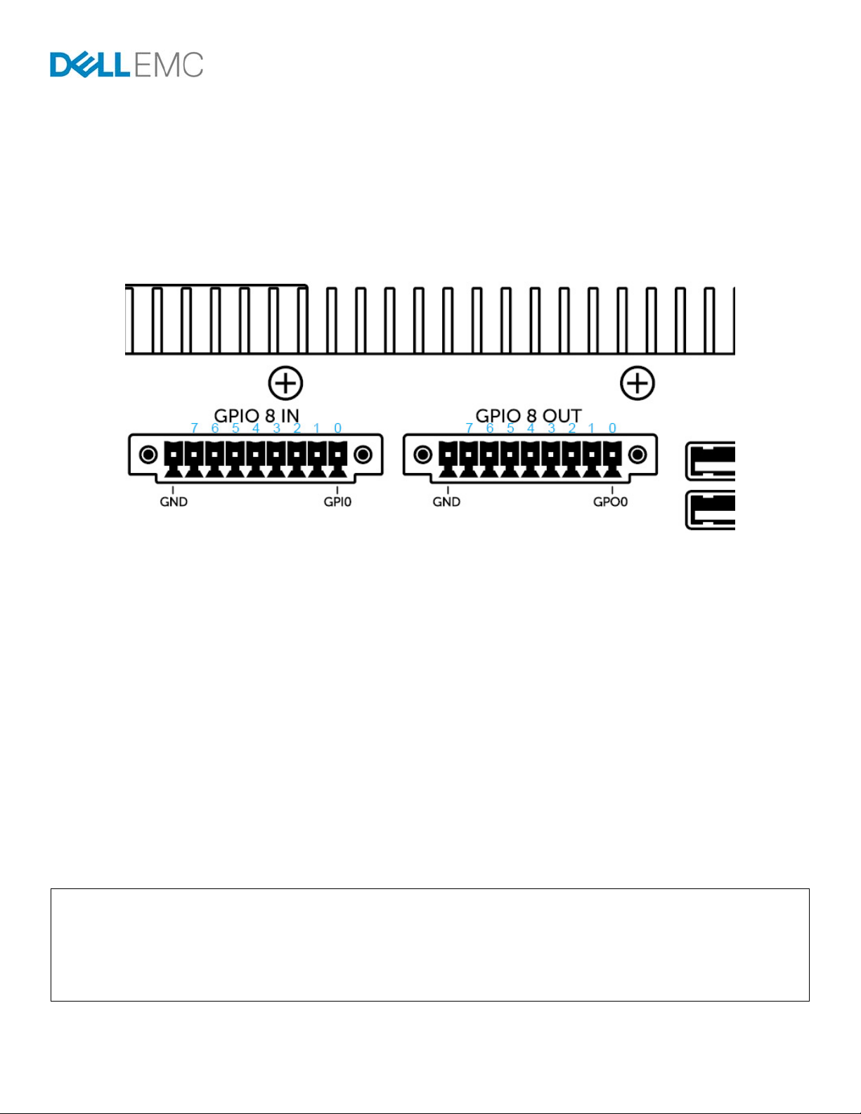
The Dell Embedded Box PC 5000 provides 16 General Purpose I/O (G PIO ) pins organized into two groups of eight pins:
GPIO 8 IN (GPI0 to GPI7) for input
GPIO 8 OUT (GPO0 to GPO7) for output.
The pins are located on the front panels of the Embedded Box PC 5000. See Figure 1 for the placements.
Figure 1
The GPIO pins are implemented by an on-board Super IO chip, the Nuvoton NCT6793D. The controller interfaces with the host
processor through the Low Pin Count (LPC) bus.
Depending on the hardware design of the Intel Architecture-based PC, the soft ware accesses the LPC d evice b y readi ng or writing to
the 2Eh/2Fh or 4Eh/4Fh IO ports.
On the Embedded Box PC 5000, the Super IO chip is accessed through the 2Fh/2Fh IO ports. The Super IO is typicall y controlled by
the kernel driver or by the BIOS. This document describes an alternative approach to control the Super IO in a user space program
which reads and writes the IO ports.
RESERVE THE IO RANGE FOR CALLER PROCESS
Before the user-space program can access any ports, it has to gain the permission to do so. This is done by calling th e ioperm function
before any I/O port can be accessed. The call of ioperm requires the program to have root privileges – you can either run the program
as the root user or make it setuid root.
See the source code example shown below. It gives access to two IO ports 0x2E through 0x2F. The last argument is a Boolean value
specifying whether to grant or to remove the access.
#include <unistd.h>
...
ioperm(0x2E, 2, 1);
setuid(getuid()); // to drop root privileges, if this is a setuid-root file
3
Page 4

The root privileges can be dropped after calling the ioperm function. A setuid() to a non-ro ot user does not disable the access to the
ports 2Eh and 2Fh, whose permissions have been granted in the example source code.
The permission to access the IO port can be dropped at the end of the program by using the source code shown below. This is optional
because the permission is removed with the process as it exits.
ioperm(0x2E, 2, 0);
ACCESS THE SUPER IO CHIP
The Super IO chip supports multiple functions such as monitoring fan speeds and power supply voltage, providing I2C bus interface
and UART ports. GPIO is one the functionalities provided by the chip.
All accesses to the Super IO are made through the IO ports; 2Eh and 2Fh. The read/write operation performed on these ports are
transformed into LPC bus cycles for the host processor to interact with the Super IO.
#define LPC_ADDR_PORT 0x2E
#define LPC_DATA_PORT 0x2F
...
outb(0x87, LPC_ADDR_PORT);
outb(0x87, LPC_ADDR_PORT);
In the above sample source code, the byte 0x87 is written twice in a row to the IO port 0x2E. This allows the Super IO chip to enter its
Extended Function Mode, where data updates to the chip are allowed.
To leave this mode and for safety reasons, write 0xAA to the same port as shown below:
outb(0xAA, LPC_ADDR_PORT);
As the access and exit of the Extended Function Mode are frequently needed in the program, rewrite them into function s for ease of
use:
void enter_extended_function_mode()
{
outb(0x87, LPC_ADDR_PORT);
outb(0x87, LPC_ADDR_PORT);
}
void leave_extended_function_mode()
{
outb(0xAA, LPC_ADDR_PORT);
}
4
Page 5

ACCESS THE GPO (OUTPUT) PINS
The eight output pins GPIO 8 OUT (GPO0, GPO1,… and GPO7) are controlled on the virtual device 8 on the Super IO chip. To control
the GPIO pins, select the device first.
See the example which writes the data value 8 to the register 07h on the chip.
outb(0x07, LPC_ADDR_PORT);
outb(8, LPC_DATA_PORT);
In the following example, the address of the register is written to the port 2Eh (i.e. LPC_ADDR_PORT). The data is written to the port
2Fh (i.e. LPC_DATA_PORT).
As these operations are frequently required, you can write a dedicated function for register-write for future use.
void lpc_reg_write(int reg, int val)
{
outb(reg, LPC_ADDR_PORT);
outb(val, LPC_DATA_PORT);
}
...
// Select device 8
lpc_reg_write(0x07, 8); // write value 8 to register 0x07
Write a dedicated function for register-read:
int lpc_reg_read(int reg)
{
outb(reg, LPC_ADDR_PORT);
return inb(LPC_DATA_PORT);
}
To change the levels of the GPO pins, write a byte to the register E1h after the virtual device has been selected.
Each bit in the byte specifies the level of a GPO pin as shown in the table:
GPO7 GPO6 GPO5 GPO4 GPO3 GPO2 GPO1 GPO0
Bit 7 Bit 6 Bit 5 Bit 4 Bit 3 Bit 2 Bit 1 Bit 0
For example, the value 0x01 (“0000 0001” in binary) sets the first pin to high and sets the upper 7 pins to low:
lpc_reg_write(0xE1, 0x01);
5
Page 6

Each bit of the read byte indicates the current level of a pin.
The following code gives a more complete example. It is a function to change the level of the pin specified by the given parameter “pin”,
instead of changing all the pins. The value of the parameter “pin” ranges from 0 to 7 to indicate the pin in GPO0 to GPO7.
void set_pin_level(int pin, int level)
{
enter_extended_function_mode();
// Select virtual device 8
lpc_reg_write(0x07, 8);
// Read pin data
int bit_map = lpc_reg_read(0xE1);
if ( level ) // change pin to high
bit_map |= (1 << pin);
else // change pin to low
bit_map &= ~(1 << pin);
// Write pin data
lpc_reg_write(0xE1, bit_map);
leave_extended_function_mode();
}
READ THE GPI (INPUT) PINS
The eight input pins GPIO 8 IN (GPI0, GPI1,… and GPI7) are controlled on the virtual device 7 on the Super IO chip. The way to
access GPI pins is very similar with GPO pins, except for the following differences:
The virtual device number is different.
The data register address is different.
The data register for GPI pins is read-only.
Select the virtual device 7 on the Super IO chip before any pins are accessed:
lpc_reg_write(0x07, 7); // write value 7 to register 0x07
The address of the data register is F5h. Read a byte from the data register to retrieve the levels of the eight GPI pins:
int bit_map = lpc_reg_read(0xF5);
6
Page 7

APPENDIX: FULL SOURCE CODE OF AN EXAMPLE PROGRAM
#include <stdlib.h>
#include <stdio.h>
#include <string.h>
#include <errno.h>
#include <unistd.h>
#include <sys/io.h>
#define GPIO_CAP_OUTPUT 1
#define GPIO_CAP_INPUT 2
#define GPIO_CAP_INOUT (GPIO_CAP_OUTPUT|GPIO_CAP_INPUT)
#define GPIO_MODE_UNKNOWN 0
#define GPIO_MODE_OUTPUT 1
#define GPIO_MODE_INPUT 2
enum pin_number {
PIN_GPO0,
PIN_GPO1,
PIN_GPO2,
PIN_GPO3,
PIN_GPO4,
PIN_GPO5,
PIN_GPO6,
PIN_GPO7,
PIN_GPI0,
PIN_GPI1,
PIN_GPI2,
PIN_GPI3,
PIN_GPI4,
PIN_GPI5,
PIN_GPI6,
PIN_GPI7,
MAX_PIN_NUM,
};
typedef struct {
int capability;
int mode;
} gpio_pin;
typedef struct {
int signature;
gpio_pin pins[MAX_PIN_NUM];
} gpio_controller;
#define LPC_ADDR_PORT 0x2E
#define LPC_DATA_PORT 0x2F
#define MAGIC_KEY 0x36D4EBAC
typedef struct {
int device_num;
int base_port;
} sio_device;
sio_device sio_devices[] =
{
{
.device_num = 8,
7
Page 8

.base_port = 0xE0,
},
{
.device_num = 7,
.base_port = 0xF4,
},
};
void enter_extended_function_mode()
{
outb(0x87, LPC_ADDR_PORT);
outb(0x87, LPC_ADDR_PORT);
}
void leave_extended_function_mode()
{
outb(0xAA, LPC_ADDR_PORT);
}
void lpc_reg_write(int reg, int val)
{
outb(reg, LPC_ADDR_PORT);
outb(val, LPC_DATA_PORT);
}
int lpc_reg_read(int reg)
{
outb(reg, LPC_ADDR_PORT);
return inb(LPC_DATA_PORT);
}
gpio_controller *gpio_initialize()
{
int i, rc;
gpio_controller *gc;
gc = malloc(sizeof(*gc));
if ( gc == NULL ) {
fprintf(stderr, "%s: no memory error\n", __FUNCTION__);
return NULL;
}
rc = ioperm(LPC_ADDR_PORT, 2, 1);
if ( rc ) {
fprintf(stderr, "%s: failed to reserve IO ports: %s\n",
__FUNCTION__, strerror(errno));
free(gc);
return NULL;
}
// The caller of ioperm() needs root privilege to get the permission of
// IO ports. In order to allow a normal user (non-root) running this program,
// "setuid" could be used for this purpose:
// 1. Change the owner of executable file to root:root
// 2. Change the mode of executable file to 4755
// After the call of ioperm(), change the effective uid of current process
// from root uid to the real uid, which is returned from getuid(), i.e. uid
// of the user who actually runs this process), to drop the root privilege.
setuid(getuid());
// Apply board-level contraints to pins
8
Page 9

for ( i = PIN_GPO0 ; i <= PIN_GPO7 ; i++ ) {
gc->pins[i].mode = GPIO_MODE_OUTPUT;
// we do not allow user to change pin direction as input
gc->pins[i].capability = GPIO_CAP_OUTPUT;
}
for ( i = PIN_GPI0 ; i <= PIN_GPI7 ; i++ ) {
gc->pins[i].mode = GPIO_MODE_INPUT;
// we do not allow user to change pin direction as output
gc->pins[i].capability = GPIO_CAP_INPUT;
}
enter_extended_function_mode();
int bmp = 0;
for ( i = 0 ; i < MAX_PIN_NUM ; i++ ) {
int bit_index = i % 8;
if ( gc->pins[i].mode == GPIO_MODE_INPUT )
bmp |= (1 << bit_index);
if ( bit_index == 7 ) {
int byte_index = i / 8;
int device_num = sio_devices[byte_index].device_num;
int base_port = sio_devices[byte_index].base_port;
// Select device
lpc_reg_write(0x07, device_num);
// Write bmp to base_port of GPIO
lpc_reg_write(base_port, bmp);
bmp = 0;
}
}
leave_extended_function_mode();
gc->signature = MAGIC_KEY;
return gc;
}
void gpio_exit(gpio_controller *gc)
{
if ( gc == NULL || gc->signature != MAGIC_KEY )
return;
// Release the IO ports
ioperm(LPC_ADDR_PORT, 2, 0);
gc->signature = 0;
free(gc);
}
#define VERIFY_PARAMETERS(handle, pin) \
if ( handle == NULL || handle->signature != MAGIC_KEY ) { \
fprintf(stderr, "%s: the given handle is invalid\n", __FUNCTION__); \
return -EINVAL; \
} \
else if ( pin < 0 || pin >= MAX_PIN_NUM ) { \
fprintf(stderr, "%s: pin number %d is invalid\n", __FUNCTION__, pin); \
return -EINVAL; \
}
int gpio_pin_set_level(gpio_controller *gc, int pin, int level)
{
int bit, bmp;
VERIFY_PARAMETERS(gc, pin);
9
Page 10

if (gc->pins[pin].mode != GPIO_MODE_OUTPUT) {
fprintf(stderr, "%s: pin %d is not an output pin\n", __FUNCTION__, pin);
return -EINVAL;
}
int index = pin / 8;
int dev_num = sio_devices[index].device_num;
int base_port = sio_devices[index].base_port;
enter_extended_function_mode();
lpc_reg_write(0x07, dev_num);
bmp = lpc_reg_read(base_port+1);
bit = (1 << (pin % 8));
if ( level )
bmp |= bit;
else
bmp &= ~bit;
lpc_reg_write(base_port+1, bmp);
leave_extended_function_mode();
return 0;
}
int gpio_pin_get_level(gpio_controller *gc, int pin, int *level)
{
int index, dev_num, base_port, bmp;
VERIFY_PARAMETERS(gc, pin);
index = pin / 8;
dev_num = sio_devices[index].device_num;
base_port = sio_devices[index].base_port;
enter_extended_function_mode();
lpc_reg_write(0x07, dev_num);
bmp = lpc_reg_read(base_port+1);
leave_extended_function_mode();
*level = !!(bmp & (1 << (pin % 8)));
return 0;
}
int gpio_pin_set_direction(gpio_controller *gc, int pin, int dir)
{
int index, dev_num, base_port, bmp;
VERIFY_PARAMETERS(gc, pin);
// On Embedded Box PC 5000 system, change the directions of GPIO pins is not allowed
if ( dir == GPIO_MODE_OUTPUT ) {
if ( !(gc->pins[pin].capability & GPIO_CAP_OUTPUT) ) {
fprintf(stderr, "%s: pin number %d could not be output\n",
__FUNCTION__, pin);
return -EINVAL;
}
}
else if ( dir == GPIO_MODE_INPUT ) {
if ( !(gc->pins[pin].capability & GPIO_CAP_INPUT) ) {
fprintf(stderr, "%s: pin number %d could not be input\n",
10
Page 11

__FUNCTION__, pin);
return -EINVAL;
}
}
else
return -EINVAL;
gc->pins[pin].mode = dir;
index = pin / 8;
dev_num = sio_devices[index].device_num;
base_port = sio_devices[index].base_port;
enter_extended_function_mode();
lpc_reg_write(0x07, dev_num);
bmp = lpc_reg_read(base_port);
if ( dir == GPIO_MODE_INPUT )
bmp |= (1 << (pin % 8));
else
bmp &= ~(1 << (pin % 8));
lpc_reg_write(base_port, bmp);
leave_extended_function_mode();
return 0;
}
int gpio_pin_get_direction(gpio_controller *gc, int pin, int *dir)
{
VERIFY_PARAMETERS(gc, pin);
*dir = gc->pins[pin].mode;
return 0;
}
int main(int argc, char** argv)
{
int rc, level, dir;
gpio_controller *gc = gpio_initialize();
if ( !gc ) {
fprintf(stderr, "Failed to initialize Embedded Box PC 5000 GPIO controller\n");
return -1;
}
printf("Set level of PIN_GPO0 to 0\n");
rc = gpio_pin_set_level(gc, PIN_GPO0, 0);
if ( rc )
printf("error happened\n");
rc = gpio_pin_get_level(gc, PIN_GPI0, &level);
if ( rc )
printf("error happened\n");
else
printf("Read PIN_GPI0 level = %d\n", level);
printf("Set level of PIN_GPO0 to 1\n");
rc = gpio_pin_set_level(gc, PIN_GPO0, 1);
if ( rc )
printf("error happened\n");
rc = gpio_pin_get_level(gc, PIN_GPI0, &level);
11
Page 12

if ( rc )
printf("error happened\n");
else
printf("Read PIN_GPI0 level = %d\n", level);
gpio_exit(gc);
return 0;
}
12
 Loading...