

Dell Edge Gateway 3002 Installation And Operation Manual

Dell Edge Gateway 3002
Installation and Operation Manual
Computer Model: Dell Edge Gateway 3002
Regulatory Model: N03G
Regulatory Type: N03G001

Notes, cautions, and warnings
NOTE: A NOTE indicates important information that helps you make better use of your product.
CAUTION: A CAUTION indicates either potential damage to hardware or loss of data and tells you how to avoid the
problem.
WARNING: A WARNING indicates a potential for property damage, personal injury, or death.
© 2017-2018 Dell Inc. or its subsidiaries. All rights reserved. Dell, EMC, and other trademarks are trademarks of Dell Inc. or its subsidiaries. Other
trademarks may be trademarks of their respective owners.
2018 - 01
Rev. A04

Contents
1 Overview......................................................................................................................... 5
2 System views..................................................................................................................6
Top view.............................................................................................................................................................................6
Bottom view.......................................................................................................................................................................7
Left view.............................................................................................................................................................................7
Right view.........................................................................................................................................................................10
3 Installing your Edge Gateway..........................................................................................11
Safety and regulatory information......................................................................................................................................11
Professional installation instructions............................................................................................................................12
Instructions d'installation professionnelles................................................................................................................... 12
Federal Communication Commission interference statement......................................................................................12
Industry Canada statement.........................................................................................................................................13
Setting up your Edge Gateway..........................................................................................................................................14
Activating your mobile broadband service......................................................................................................................... 19
Mounting your Edge Gateway.......................................................................................................................................... 20
Mounting the Edge Gateway using the standard-mount bracket................................................................................20
Mounting the Edge Gateway using quick-mount bracket............................................................................................27
Attaching the cable control bars to the standard-mount bracket............................................................................... 35
Mounting the Edge Gateway on a DIN rail using the DIN-rail bracket.........................................................................38
Mounting the Edge Gateway using the perpendicular mount......................................................................................41
Mounting the Edge Gateway using a VESA mount.....................................................................................................44
4 Setting up the ZigBee dongle........................................................................................46
5 Setting up the operating system................................................................................... 47
Windows 10 IoT Enterprise LTSB 2016..............................................................................................................................47
Boot up and login – Remote system conguration..................................................................................................... 47
Boot up and login—Static IP system conguration.....................................................................................................47
Restoring Windows 10 IoT Enterprise LTSB 2016....................................................................................................... 48
Windows 10 IOT Enterprise LTSB 2016 basic functions.............................................................................................. 48
Ubuntu Core 16................................................................................................................................................................ 49
Overview....................................................................................................................................................................49
Boot up and log in – Remote system conguration....................................................................................................50
Boot up and log in – Static IP system conguration...................................................................................................50
Updating operating system and applications.............................................................................................................. 50
Additional Ubuntu commands......................................................................................................................................51
Ubuntu Network Manager..........................................................................................................................................52
Security......................................................................................................................................................................55
Watchdog Timer (WDT).............................................................................................................................................55
Cloud LED On/O......................................................................................................................................................56
3

Global Positioning Systems (GPS)..............................................................................................................................56
Snappy auto update/Autopilot....................................................................................................................................56
Accessing Snappy Store/Snapweb............................................................................................................................ 56
CAN module...............................................................................................................................................................58
Sensors......................................................................................................................................................................58
Ignition Pin................................................................................................................................................................. 59
System Power Management...................................................................................................................................... 60
Restoring Ubuntu Core 16..........................................................................................................................................60
Flashing a new OS image........................................................................................................................................... 62
Creating the recovery USB ash drive..............................................................................................................................62
CAN module.....................................................................................................................................................................63
6 Accessing and updating BIOS....................................................................................... 64
Accessing BIOS settings.................................................................................................................................................. 64
Updating BIOS................................................................................................................................................................. 64
Using the USB invocation script.................................................................................................................................64
Flashing the BIOS from a USB ash drive.................................................................................................................. 65
Updating the BIOS on a Windows system..................................................................................................................65
Using UEFI capsule update on an Ubuntu system......................................................................................................65
Dell Command | Congure (DCC)..............................................................................................................................66
Edge Device Manager (EDM).................................................................................................................................... 66
Default BIOS settings....................................................................................................................................................... 67
System conguration (BIOS level 1)............................................................................................................................67
Security (BIOS level 1)................................................................................................................................................67
Secure boot (BIOS level 1)......................................................................................................................................... 69
Performance (BIOS level 1)........................................................................................................................................69
Power management (BIOS level 1).............................................................................................................................69
POST behavior (BIOS level 1).....................................................................................................................................70
Virtualization support (BIOS level 1)........................................................................................................................... 70
Maintenance (BIOS level 1)........................................................................................................................................ 70
System logs (BIOS level 1)...........................................................................................................................................71
7 References.................................................................................................................... 72
8 Appendix....................................................................................................................... 73
Antenna specications......................................................................................................................................................73
De-mounting from DIN-rail bracket...................................................................................................................................74
Connecting to the Edge Gateway.....................................................................................................................................75
Windows 10 IoT Enterprise LTSB 2016........................................................................................................................75
Ubuntu Core 16.......................................................................................................................................................... 75
9 Contacting Dell..............................................................................................................77
4

1
Overview
The Edge Gateway 3000 Series is an Internet-of-Things (IoT) device. It is mounted at the edge of a network, enabling you to collect,
secure, analyze, and act on data from multiple devices and sensors. It enables you to connect with devices used in transportation,
building automation, manufacturing, and other applications. The Edge Gateway has a low-power architecture, which is capable of
supporting industrial automation workloads while remaining fanless to satisfy environmental and reliability requirements. It supports
Windows 10 IoT Enterprise LTSB 2016 and Ubuntu Core 16 operating systems.
5
2
System views
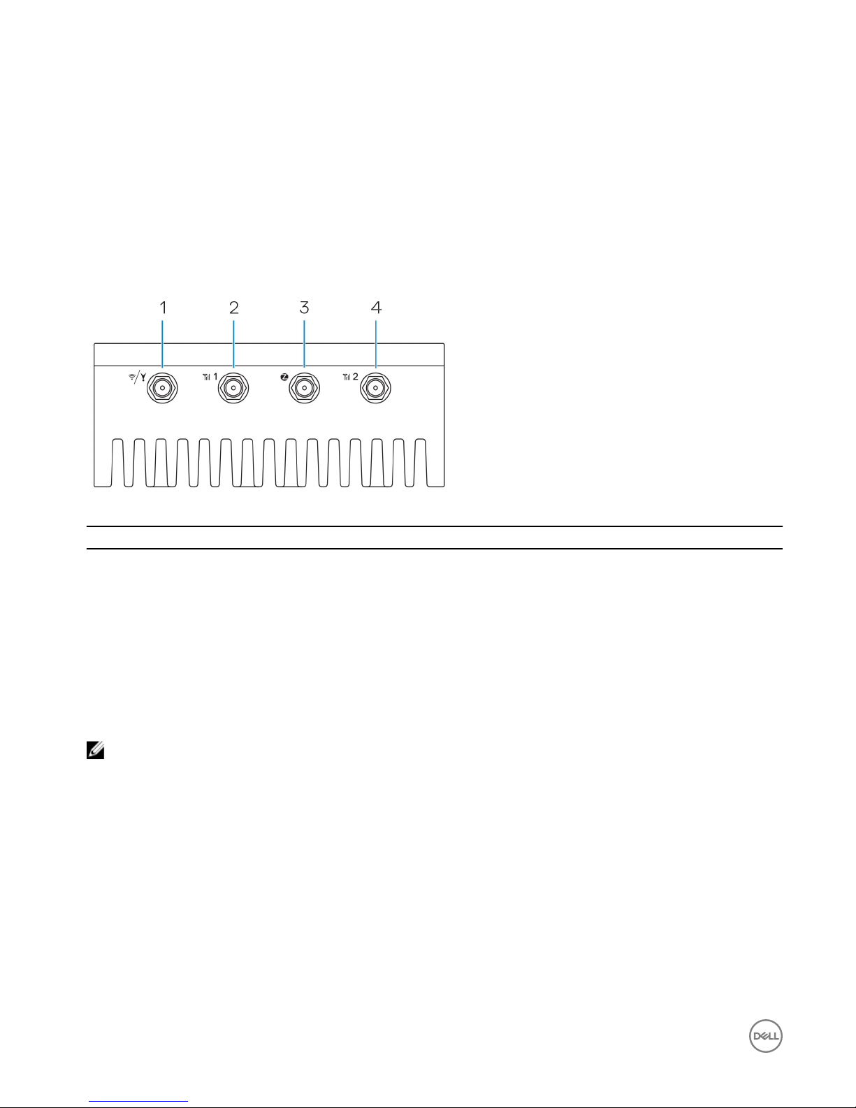
Top view
Table 1. Top view
Features
1 WLAN, Bluetooth, or GPS connector Connect the antenna to increase the range and strength of
wireless, Bluetooth, or satellite signals.
2 Mobile broadband antenna-connector one (3G/
LTE)
Connect the mobile broadband antenna to increase the range and
strength of mobile broadband signals.
3 ZigBee antenna connector Connect the ZigBee antenna for intermittent data transmissions
from a ZigBee-compliant sensor or input device.
4 Mobile broadband antenna-connector two (LTE
Auxiliary only)
Connect the mobile broadband antenna to increase the range and
strength of mobile broadband signals.
NOTE: Depending on the conguration ordered, some of the antenna connectors may not be present or may be capped.
For more information about connecting antennas to the Edge Gateway, see the documentation that is shipped with the
antenna.
6

Bottom view
Table 2. Bottom view
Features
1 Service Tag label The Service Tag is a unique alphanumeric identier that enables
the Dell service technicians to identify the hardware components
in your Edge Gateway and access warranty information.
2 Earth ground A large conductor attached to one side of the power supply, which
serves as the common return path for current from many dierent
components in the circuit.
Left view
Table 3. Left view
Features
1 Intrusion switch An intrusion event is triggered when the enclosure (in which the Edge Gateway is
installed) is opened.
NOTE: External enclosure is sold separately.
7

Features
NOTE: An intrusion event is triggered by a third-party enclosure to the Edge
Gateway through a sensor. The sensor should have a cable that is compatible
with the intrusion switch connector on the Edge Gateway.
2 Power or ignition port Connect a 12-57 VDC (1.08-0.23 A) power cable to supply power to the Edge
Gateway.
NOTE: Power cable is sold separately.
NOTE: For marine applications, limit input voltage to 12-48 VDC. The cable
length for rail applications must not exceed 30 meters.
3 Power and System status light Indicates the power status and system status.
4 WLAN or Bluetooth status light Indicates if WLAN or Bluetooth is ON or OFF.
5 Cloud-connection status light Indicates the cloud connection status.
6 Ethernet port one (with Power
over Ethernet support)
Connect an Ethernet (RJ45) cable to gain network access. Provides data transfer
speeds up to 10/100 Mbps and supports Alternative A of the IEEE 802.3af standard.
NOTE: The Edge Gateway is an IEEE 802.3af Alternative A compliant
Powered Device (PD).
NOTE: To comply with EU Declaration of Conformity (DoC), ensure cable
length from the system to the device does not exceed 30 meters.
NOTE: To comply with regulatory requirements in Brazil, ensure cable length
from the system to the device does not exceed 10 meters.
7 USB 3.0 port
1
Connect a USB enabled device. Provides data transfer speeds up to 5 Gbps.
8 SIM card slot (optional) Insert a micro-SIM card into the slot.
9 SD card slot (optional) Insert a micro-SD card into the slot.
NOTE: Remove the SD card slot ller before inserting a micro-SD card.
10 Quick Resource Locator label Scan with a QR reader to access documentation and other system information.
11 micro-SIM or micro-SD card
access door
Open the access door to access the micro-SIM or micro-SD card.
1
USB power is limited to 0.6 A/3 W.
Table 4. Status-light indicators
Function Indicator Color Control Status
System Power status and
System status
Green or Amber BIOS O: System o
On (Solid Green):
System on or Boot
successful
On (Solid Amber):
Power up or boot fail
Blinking Amber: Fault or
error
8
Function Indicator Color Control Status
WLAN or Bluetooth Green Hardware O: WLAN or Bluetooth
module is o
On: WLAN or Bluetooth
module is on
Cloud Green Software O: No connection to
the cloud device or
service
On: Edge Gateway
connected to a cloud
device or service
Blinking Green: Activity
to a cloud device or
service
LAN (RJ-45) Link Green/Amber Driver (LAN) O: No network link or
cable is not connected
On (Green): High-speed
connection (100 Mbps)
On (Amber): Low-speed
connection (10 Mbps)
Activity Green Driver (LAN) O: No activity on link
Blinking Green: LAN
activity. The blink rate is
related to packet
density.
NOTE: The power and system status light may operate dierently during dierent boot-up scenarios, for example, when
a USB script le is run during boot-up.
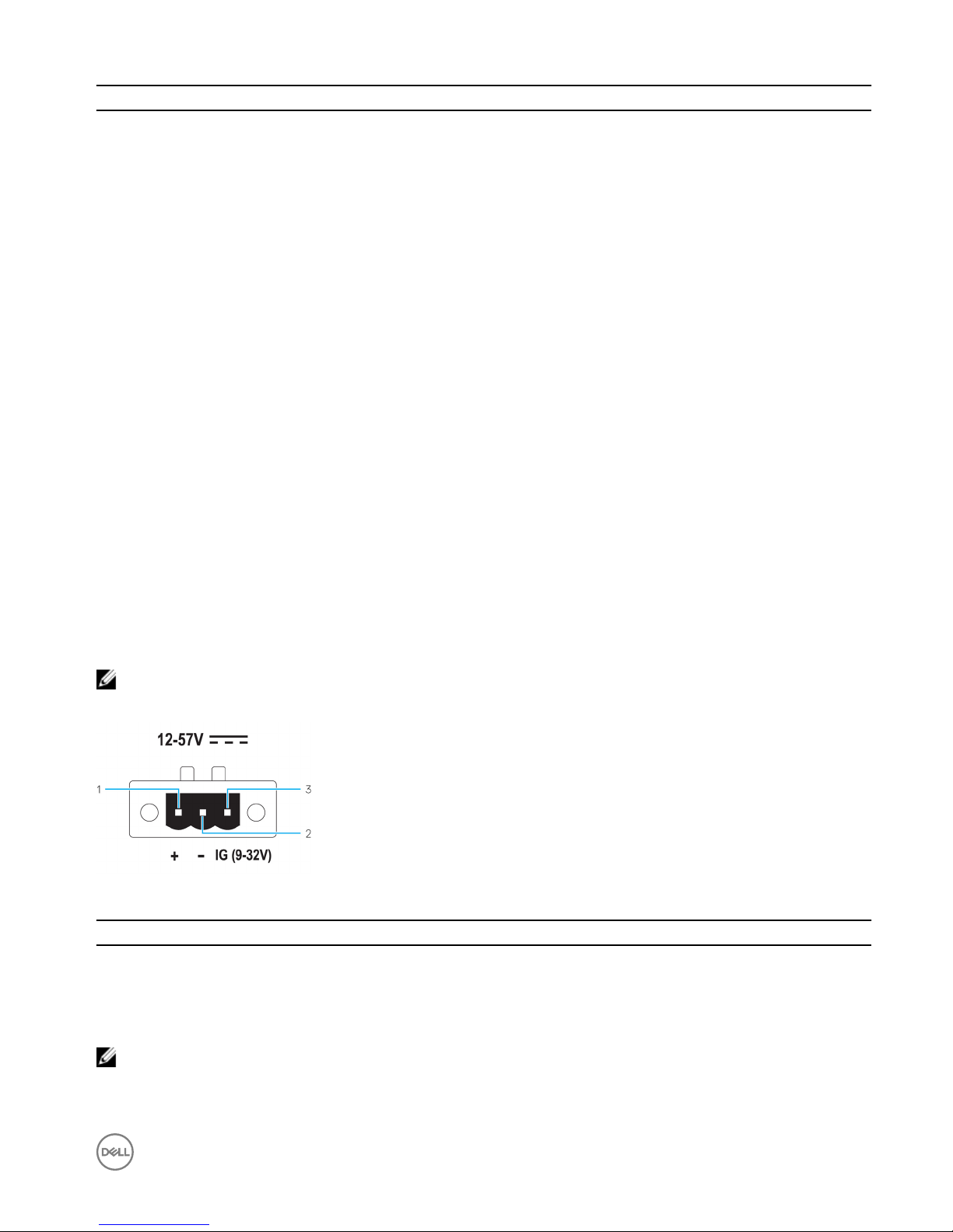
Table 5. Power connector pin denition details
Pin Signal Function
1 DC+ 12–57 VDC power
2 DC– Ground
3 IG 9–32 VDC ignition
NOTE: Pin 3 (IG) is connected to the vehicle's ignition status indicator (optional) or a wake pin. A voltage of more than 9
V on the signal indicates that the vehicle’s engine is running. The Ignition or Wake pin is used to prevent the draining of
the vehicle battery when the vehicle is turned o for an extended amount of time.
9

NOTE: The IG signal can be used to gracefully shutdown or enter low-power state when the vehicle is turned o (battery
powered). It can also be used for powering on the Edge Gateway when the vehicle starts.
Right view
Table 6. Right view—3002
Features
1 CANbus port Enables the CANbus connection.
2 USB 2.0 port
1
Connect a USB enabled device. Provides data transfer speeds up
to 480 Mbps.
3 Ethernet port two (Non-PoE) Connect an Ethernet (RJ45) cable for network access. Provides
data transfer speeds up to 10/100 Mbps.
1
USB power is limited to 0.4 A/2 W.
Table 7. CANbus-port pin denition details
Features
1 GND Ground
2 CAN-H High-level CANbus line
3 CAN-L Low-level CANbus line
10

3
Installing your Edge Gateway
WARNING: Before you begin any of the procedures in this section, read the safety and regulatory information that is
shipped with your system. For additional best practices information, go to www.dell.com/regulatory_compliance.
Safety and regulatory information
WARNING: The Edge Gateway must be installed by knowledgeable, skilled persons familiar with local and/or international
electrical codes and regulations.
WARNING: The Edge Gateway is not designed for use in wet environments. If the Edge Gateway is to be installed in a
wet environment, depending on the location and environment, it must be installed in a panel box or enclosure with an
Ingress Protection (IP) rating of IP54, IP65, or higher.
WARNING: To reduce the risk of electric shock, power to the DC+ and DC- terminals must be provided by a power supply
or transformer/rectier circuit that is designed with double-insulation. The power supply or power circuit source must
comply with local codes and regulations; for example, in the USA, NEC Class 2 (SELV/limited energy circuit, or LPS
circuitry). If powered by a battery, double-insulation is not required.
WARNING: When installing the Edge Gateway, the responsible party or integrator shall use the 12-57 VDC or Power over
Ethernet (PoE) power source 37-57 VDC, with a minimum of 13 W power already present as part of the client’s
installation.
WARNING: Ensure that the power source providing power to the Edge Gateway is reliably grounded and ltered such
that the peak-to-peak ripple component is less than 10 percent of the input DC voltage.
WARNING: When installing the Edge Gateway 3001 and 3002, use a cable appropriate for the load currents: 3-core cable
rated 5 A at 90°C (194°F) minimum, which conform to either IEC 60227 or IEC 60245. The system accepts cables from
0.8 mm to 2 mm. The maximum operating temperature of the Edge Gateway is 70⁰C (158°F). Do not exceed this
maximum temperature while operating the Edge Gateway inside an enclosure. Internal heating of the Edge Gateway
electronics, other electronics, and the lack of ventilation inside an enclosure can cause the operating temperature of the
Edge Gateway to be greater than the outside ambient temperature. Continuous operation of the Edge Gateway at
temperatures greater than 70⁰C (158°F) may result in an increased failure rate and a reduction of the product life. Ensure
that the maximum operating temperature of the Edge Gateway when placed inside an enclosure is 70⁰C (158°F) or less.
WARNING: Always ensure that the available power source matches the required input power of the Edge Gateway.
Check the input power markings next to power connector(s) before making connections. The 12-57 VDC (1.08-0.23 A) or
the PoE power source must be compliant with local Electrical Codes and Regulations.
WARNING: To ensure the protection provided by the Edge Gateway is not impaired, do not use or install the system in
any manner other than what is specied in this manual.
WARNING: If a battery is included as part of the system or network, the battery must be installed within an appropriate
enclosure in accordance with local re and electrical codes and laws.
WARNING: The system is for installation in a suitable industrial enclosure (provides electrical, mechanical, and re hazard
protection).
WARNING: The core module only can be wall-mounted (without the need for an additional enclosure).
11

Professional installation instructions
Installation personnel
This product is designed for specic applications and needs to be installed by qualied personnel with RF and regulatory-related
knowledge. The general user shall not attempt to install or change the setting.
Installation location
The product shall be installed at a location where the radiating antenna is kept 20 cm from nearby persons in its normal operation
condition in order to meet regulatory RF exposure requirements.
External antenna
Use only approved antenna(s). Non-approved antenna(s) may produce spurious or excessive RF transmitting power which may lead
to a violation of FCC/IC limits.
Installation procedure
Refer to user’s manual for installation instructions.
WARNING: Carefully select the installation position and make sure that the nal output power does not exceed the limits
described in the product’s documentation. The violation of these rules could lead to serious federal penalties.
Instructions d'installation professionnelles
Le personnel d'installation
Ce produit est conçu pour des applications spéciques et doit être installé par un personnel qualié avec RF et connaissances
connexes réglementaire. L'utilisateur ne doit pas tenter générale d'installer ou de modier le réglage.
Lieu d'installation
Le produit doit être installé à un endroit où l'antenne de rayonnement est maintenue à 20 cm de personnes à proximité dans son état
de fonctionnement normal, an de répondre aux exigences réglementaires d'exposition aux radiofréquences.
Antenne externe
Utilisez uniquement l'antenne(s) qui ont été approuvés par le demandeur. Antenne (s) peuvent produire de l'énergie RF parasite
indésirable ou excessive transmission qui peut conduire à une violation des normes de la FCC / IC est interdite et non-approuvé.
Procédure d'installation
ATTENTION: S'il vous plaît choisir avec soin la position d'installation et assurez-vous que la puissance de sortie nal ne
dépasse pas les limites xées dans les règles pertinentes. La violation de ces règles pourrait conduire à des sanctions fédérales
graves.
Federal Communication Commission interference statement
This device complies with Part 15 of the FCC Rules. Operation is subject to the following two conditions: (1) This device may not
cause harmful interference, and (2) this device must accept any interference received, including interference that may cause
undesired operation.
This equipment has been tested and found to comply with the limits for a Class A digital device, pursuant to Part 15 of the FCC
Rules. These limits are designed to provide reasonable protection against harmful interference in a residential installation. This
equipment generates, uses, and can radiate radio frequency energy and, if not installed and used in accordance with the instructions,
12

may cause harmful interference to radio communications. However, there is no guarantee that interference will not occur in a
particular installation. If this equipment does cause harmful interference to radio or television reception, which can be determined by
turning the equipment o and on, the user is encouraged to try to correct the interference by one of the following measures:
• Reorient or relocate the receiving antenna.
• Increase the separation between the equipment and receiver.
• Connect the equipment into an outlet on a circuit dierent from that to which the receiver is connected.
• Consult the dealer or an experienced radio/TV technician for help.
FCC caution:
• Any changes or modications not expressly approved by the party responsible for compliance could void the user's authority to
operate this equipment.
• This transmitter must not be co-located or operating in conjunction with any other antenna or transmitter.
Radiation exposure statement:
This equipment complies with FCC radiation exposure limits for an uncontrolled environment. This equipment should be installed and
operated with a minimum distance of 20 cm between the active transceiver and your body.
NOTE: The country code selection is for a non-US model only and is not available to all US model. Per FCC regulation, all
WiFi products marketed in the US must be xed to US operation channels only.
Industry Canada statement
This device complies with Industry Canada license-exempt RSS standard(s). Operation is subject to the following two conditions:
1. this device may not cause interference, and
2. this device must accept any interference, including interference that may cause undesired operation of the device.
Le présent appareil est conforme aux CNR d'Industrie Canada applicables aux appareils radio exempts de licence. L'exploitation est
autorisée aux deux conditions suivantes:
1. l'appareil ne doit pas produire de brouillage, et
2. l'utilisateur de l'appareil doit accepter tout brouillage radioélectrique subi, même si le brouillage est susceptible d'en
compromettre le fonctionnement.
Under Industry Canada regulations, the radio transmitter(s) may only operate using an antenna(s) of a type and maximum (or lesser)
gain approved for the transmitter(s). To reduce potential radio interference to other users, the antenna type(s) and gain(s) should be
chosen so that the Equivalent Isotropic Radiated Power (E.I.R.P.) is not more than what was approved for the transmitter(s).
This Class A digital apparatus complies with Canadian ICES-003.
Cet appareil numérique de la classe A est conforme à la norme NMB-003 du Canada.
This device complies with RSS-210 of Industry Canada. Operation is subject to the condition that this device does not cause harmful
interference.
Cet appareil est conforme à la norme RSS-210 d'Industrie Canada. L'opération est soumise à la condition que cet appareil ne
provoque aucune interférence nuisible.
This device and its antenna(s) must not be co-located or operating in conjunction with any other antenna or transmitter, except
tested built-in radios.
Cet appareil et son antenne ne doivent pas être situés ou fonctionner en conjonction avec une autre antenne ou un autre émetteur,
exception faites des radios intégrées qui ont été testées.
The County Code Selection feature is disabled for products marketed in the US/Canada.
13

La fonction de sélection de l'indicatif du pays est désactivée pour les produits commercialisés aux États-Unis et au Canada.
Radiation Exposure Statement: This equipment complies with IC radiation exposure limits set forth for an uncontrolled environment.
This equipment should be installed and operated with minimum distance of 20 cm between the active transceiver and your body.
Déclaration d'exposition aux radiations: Cet équipement est conforme aux limites d'exposition aux rayonnements IC établies pour
un environnement non contrôlé. Cet équipement doit être installé et utilisé avec un minimum de 20 cm de distance entre la source de
rayonnement et votre corps.
Setting up your Edge Gateway
NOTE: Edge Gateway mounting options are sold separately.
NOTE: Mounting can be done before or after conguring your Edge Gateway. For more information about mounting your
Edge Gateway, see Mounting your Edge Gateway.
NOTE: In some environments where the Edge Gateway may be installed, a more robust mounting method is required. For
example, for mounting in marine applications, it is recommended to use only the standard— mount bracket. The
recommendation is due to the presence of vibrations unique to the marine environment.
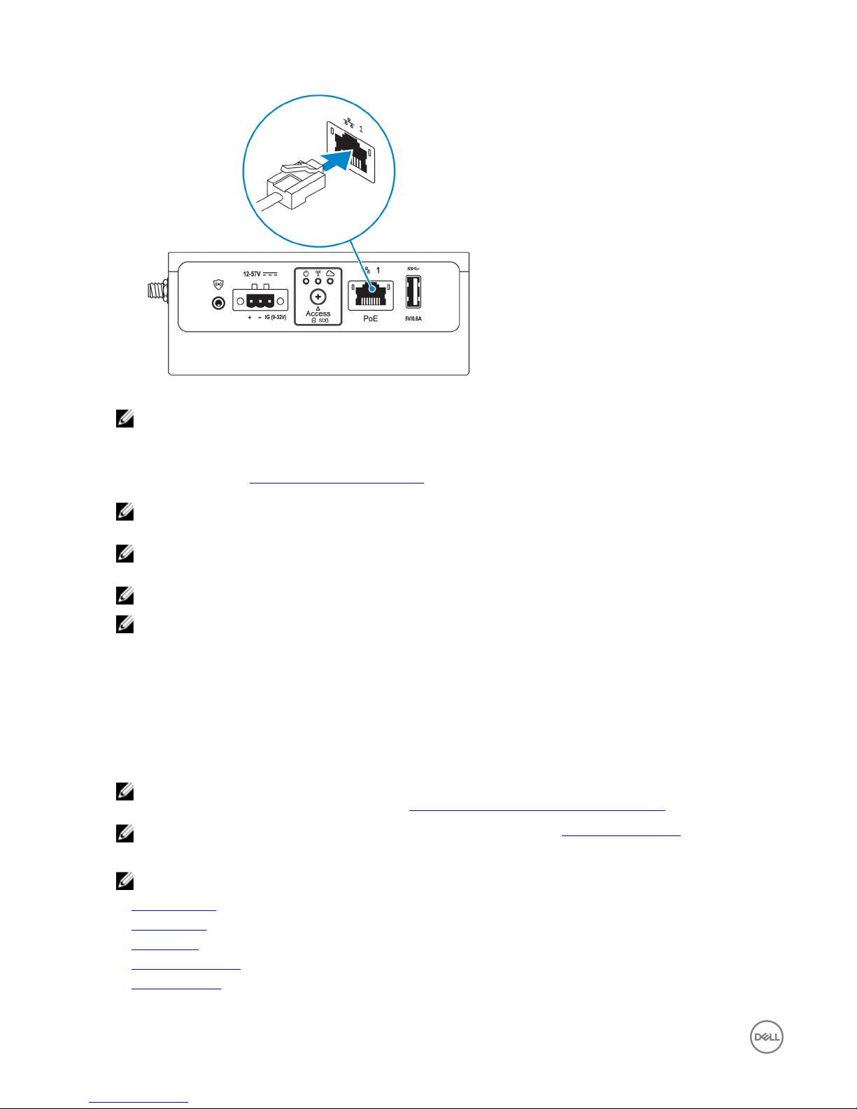
1. Connect an Ethernet cable to Ethernet port one.
2. Connect the antennas depending on the conguration ordered (optional).
NOTE: The antennas supported in the Edge Gateway vary depending on the conguration ordered.
Table 8. Antennas supported in Edge Gateway 3002
Antennas
supported
Signals
14
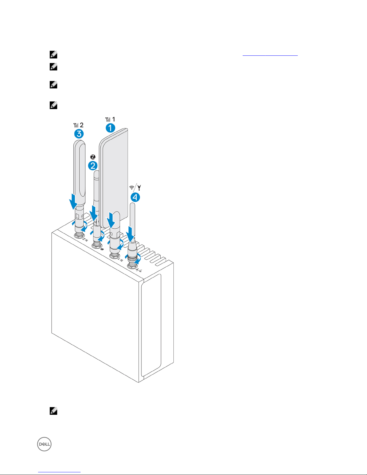
3002 Yes Yes Yes Yes Yes
NOTE: Use only the supplied antennas or third-party antennas that meet the minimum specications.
NOTE: Depending on the conguration ordered, some of the antenna connectors may not be present or may be
capped.
NOTE: Mobile broadband antenna connector two is for LTE Auxiliary only; it does not support 3G.
3. Insert the antenna into the connector.
NOTE: If you are installing multiple antennas, follow the sequence indicated in the following image.
4. Secure the antenna by tightening the rotating head of the connector until it rmly holds the antenna in the preferred position
(upright or straight).
NOTE: Antenna images are for illustrative purposes only. Actual appearance may dier from the images provided.
5. Connect all desired cables to the appropriate I/O ports on the Edge Gateway.
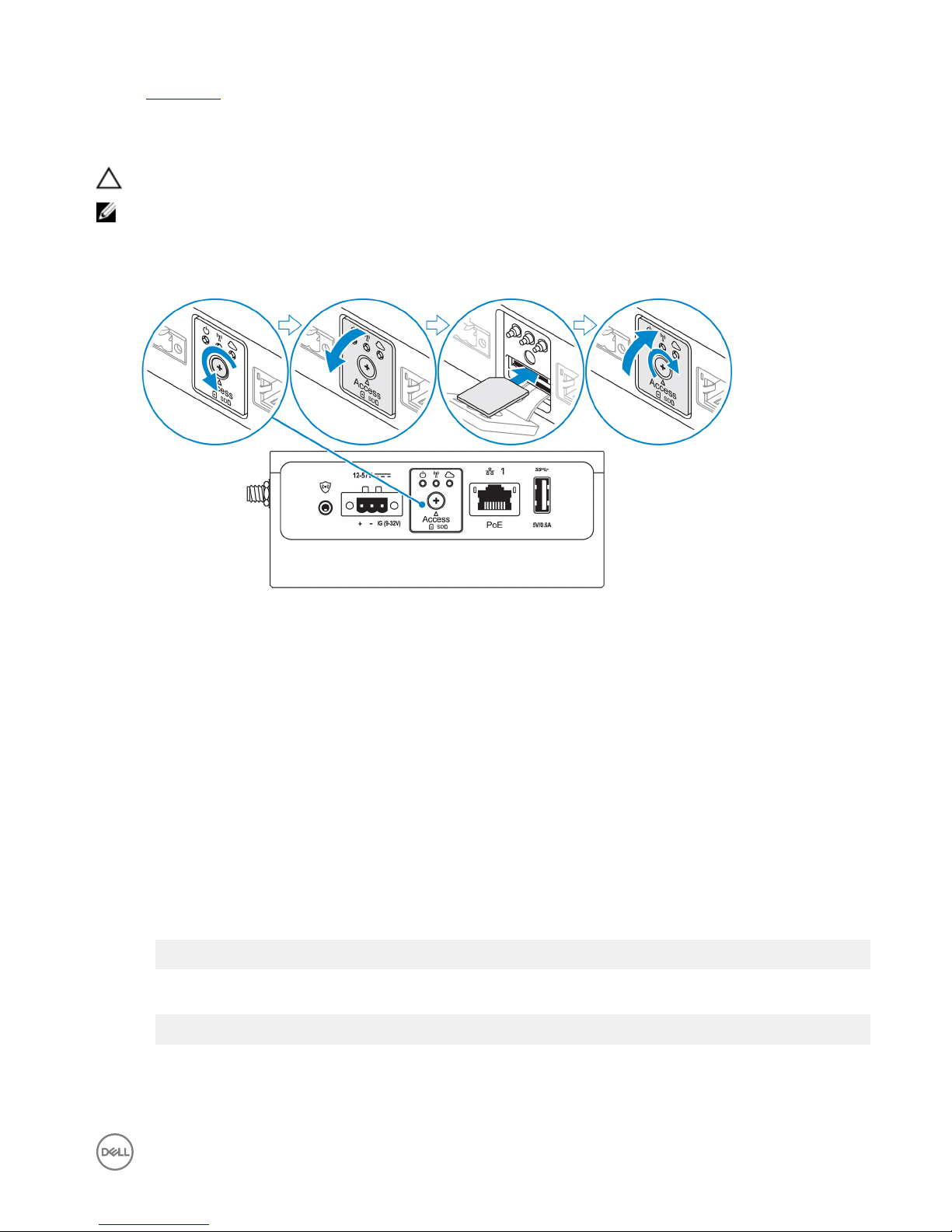
6. Open the micro-SIM or micro-SD card access door.
15
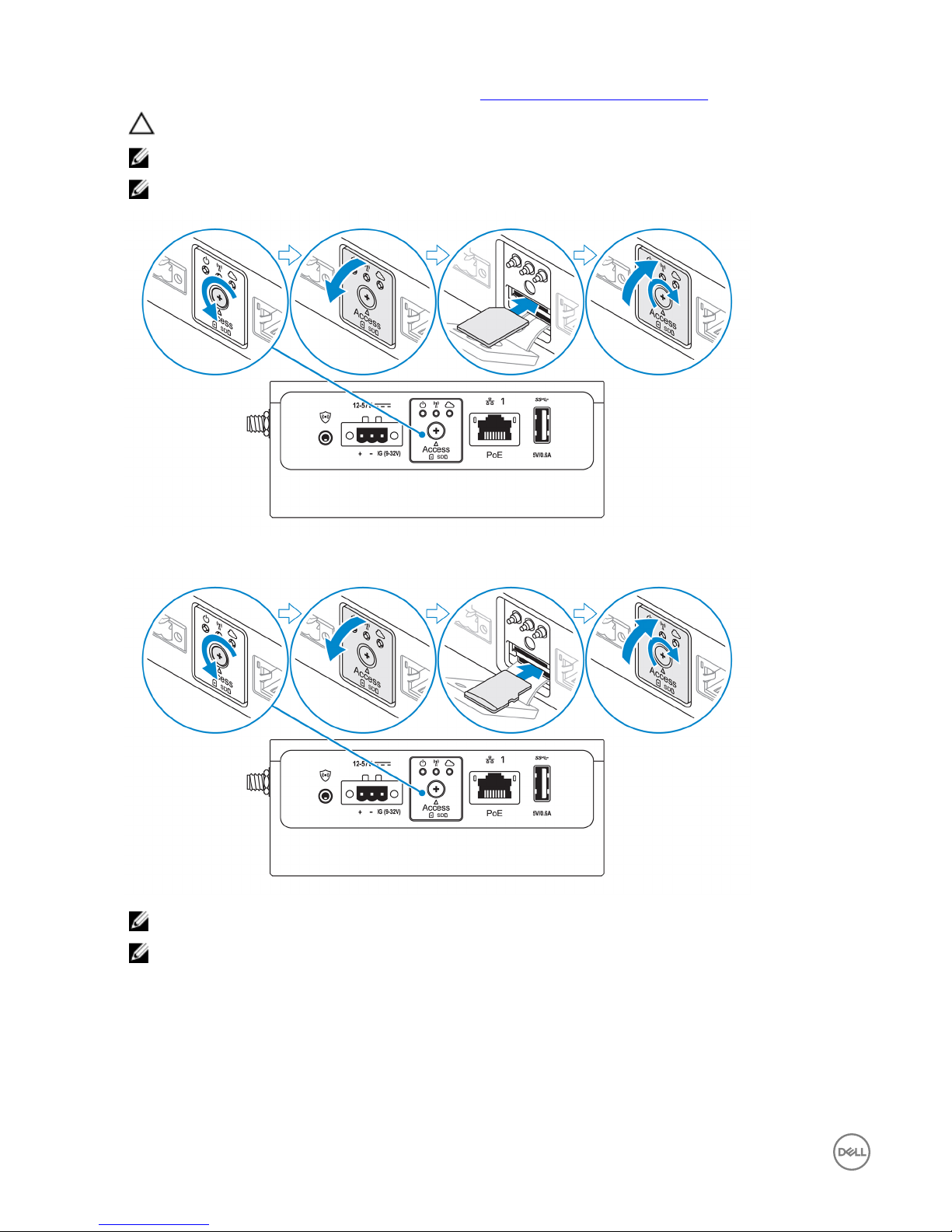
7. Insert a micro-SIM card into the top micro-SIM card slot and activate your mobile broadband service.
CAUTION: Dell recommends that you insert the micro-SIM card before turning on the Edge Gateway.
NOTE: Ensure that you rmly screw back the access door after closing.
NOTE: Contact your service provider to activate your micro-SIM card.
8. Insert a micro-SD card into the bottom micro-SD card slot.
NOTE: Remove the SD card slot ller before inserting a micro-SD card.
NOTE: Ensure that you rmly screw back the access door after closing.
9. Connect a grounding cable between the Edge Gateway and the secondary enclosure.
16
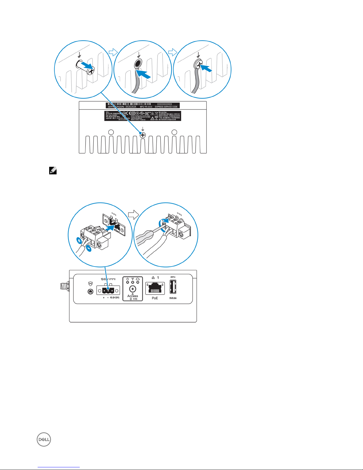
NOTE: Secondary enclosures are sold separately.
10. Connect the Edge Gateway to one of the following power sources:
• DC-IN
• PoE
17
NOTE: Shut down your system before you change the power sources.
11. Replace the dust caps on any unused ports.
12. When setting up the Edge Gateway for the rst time, complete the operating system setup.
For more information, see Setting up your operating system.
NOTE: MAC addresses and the IMEI number are available on the label at the front of the Edge Gateway. Remove the
label at install.
NOTE: The Edge Gateway is shipped with either Windows 10 IoT Enterprise LTSB 2016 or Ubuntu Core 16 operating
system.
NOTE: The default user name and password for Windows 10 IoT Enterprise LTSB 2016 is
admin
.
NOTE: The default user name and password for Ubuntu Core 16 is
admin
.
13. Access the BIOS by connecting remotely with the Dell Command | Congure application.
Windows 10 IOT Enterprise LTSB 2016
Click Start → All Programs → Dell → Command Congure → Dell Command | Congure Wizard.
Ubuntu Core 16
Use the dcc.cctk command to access the Dell Command | Congure application.
NOTE: For more information about using the Dell Command | Congure application, see the Dell Command |
Congure
Installation Guide
and
User's Guide
at www.dell.com/dellclientcommandsuitemanuals.
NOTE: For more information about BIOS settings on the Edge Gateway, see Default BIOS settings.
14. Install the Edge Gateway using one of the following mounting options:
NOTE: An open space of 63.50 mm (2.50 in) is recommended around the Edge Gateway for optimal air circulation.
• Standard mount
• DIN rail mount
• Quick mount
• Perpendicular mount
• Cable control bar
18
• VESA mount
Activating your mobile broadband service
CAUTION: Before you power on the Edge Gateway, insert a micro-SIM card.
NOTE: Ensure that the service provider has already activated the micro-SIM card before you use it in the Edge Gateway.
1. Remove the screw to open the micro-SIM card access door.
2. Insert a micro-SIM card into the top micro-SIM card slot.
3. Replace the screw, and close the micro-SIM card access door.
4. Power on the Edge Gateway.
5. Connect to a mobile network.
Windows operating system
a. Click the network icon from the taskbar, and then click Cellular.
b. Select Mobile Broadband Carrier → Advanced Options.
c. Make a note of the International Mobile Equipment Identity (IMEI) and Integrated Circuit Card Identier (ICCID).
d. Enter your APN number and any other credentials that your service provider requires.
Ubuntu operating system
a. Open the Terminal window.
b. Enter $sudo su - to access super user mode.
c. Congure the Mobile Broadband connection prole:
Command line:
network-manager.nmcli con add type <type> ifname <ifname> con-name <connection-name>
apn <apn>
Example (Verizon):
network-manager.nmcli con add type gsm ifname cdc-wdm0 con-name VZ_GSMDEMO apn
vzwinternet
19

Example (AT&T):
network-manager.nmcli con add type gsm ifname cdc-wdm0 con-name ATT_GSMDEMO apn
broadband
Example (3G):
network-manager.nmcli con add type gsm ifname cdc-wdm0 con-name 3G_GSMDEMO apn
internet
d. Connect to the mobile network:
Command line:
network-manager.nmcli con up <connection-name>
Example (Verizon):
network-manager.nmcli con up VZ_GSMDEMO
Example (AT&T):
network-manager.nmcli con up ATT_GSMDEMO
Example (3G):
network-manager.nmcli con up 3G_GSMDEMO
To disconnect from the mobile network:
Command line: network-manager.nmcli con down <connection-name>
Example (Verizon):
network-manager.nmcli con down VZ_GSMDEMO
Example (AT&T):
network-manager.nmcli con down ATT_GSMDEMO
Example (3G):
network-manager.nmcli con down 3G_GSMDEMO
Mounting your Edge Gateway
NOTE: Mounting can be completed before or after conguring your Edge Gateway.
NOTE: Mounting options are sold separately. Mounting instructions are available in the documentation shipped with the
mounting device.
NOTE: In some environments where the Edge Gateway is installed, a more robust mounting method is required. For
example, in marine applications, due to vibrations unique to that environment, only standard-mount bracket should be
used.
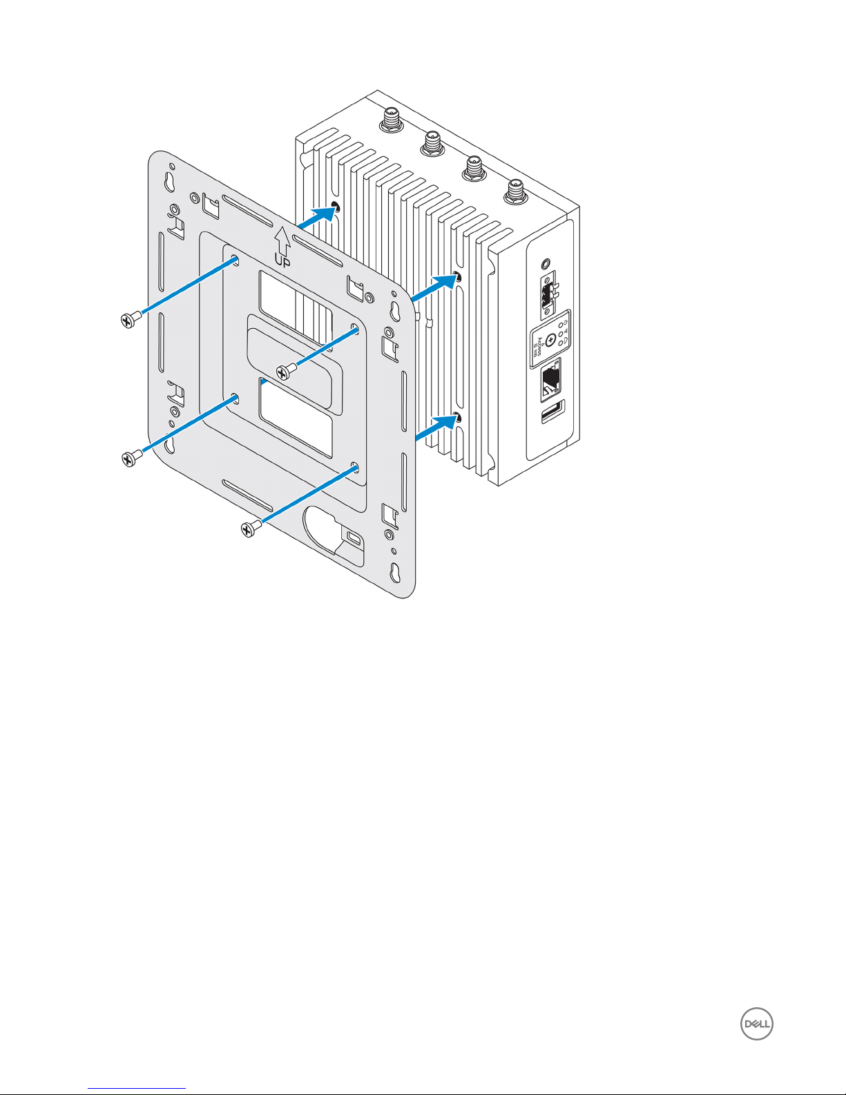
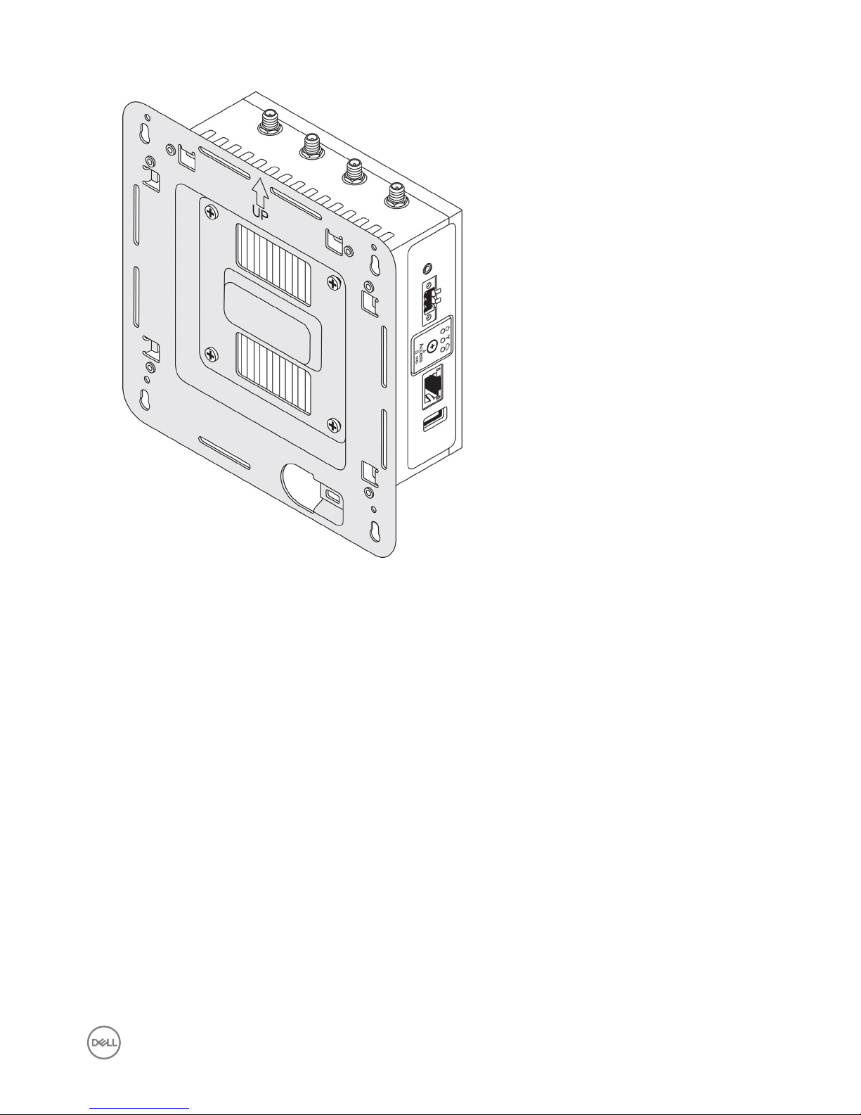
Mounting the Edge Gateway using the standard-mount bracket
Mounting dimensions
20
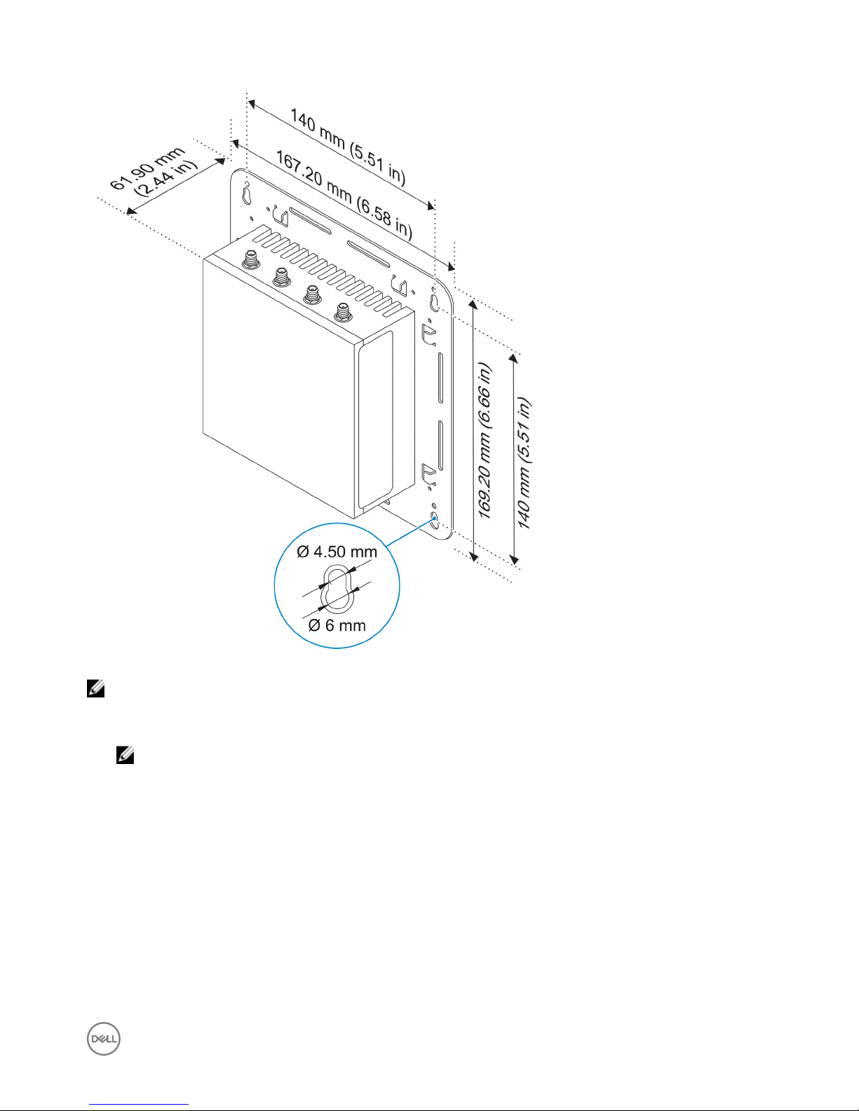
NOTE: The mounting brackets are shipped with only those screws that are required for securing the mounting brackets
to the Edge Gateway.
1. Secure the standard-mount bracket to the back of the Edge Gateway using the four M4x4.5 screws.
NOTE: Torque the screws at 8±0.5 kilograms-centimeter (17.64±1.1 pounds-inch).
21
2. Place the Edge Gateway against the wall, and align the holes in the standard-mount bracket with the holes on the wall. Screw
holes on the bracket have a diameter of 3 mm (0.12 in).
22
3. Place the standard-mount bracket on the wall, and using the holes above the screw holes on the bracket, mark the positions to
drill the four holes.
23
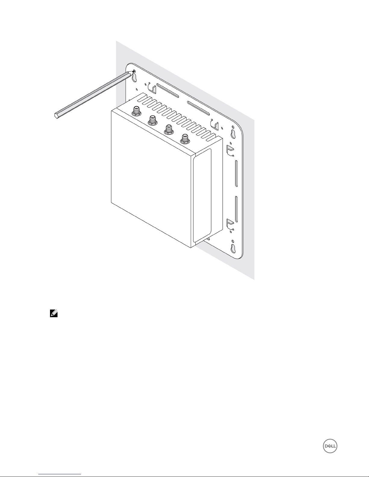
4. Drill four holes in the wall as marked.
5. Insert and tighten four screws (not supplied) to the wall.
NOTE: Purchase screws that t the diameter of the screw holes.
24
 Loading...