


Dell Edge Gateway
Service Manual
Computer Model: Dell Edge Gateway 3000 Series
Regulatory Model: N03G
Regulatory Type: N03G001

Notes, cautions, and warnings
NOTE: A NOTE indicates important information that helps you make better use of your product.
CAUTION: A CAUTION indicates either potential damage to hardware or loss of data and tells you how to avoid the
problem.
WARNING: A WARNING indicates a potential for property damage, personal injury, or death.
Copyright © 2017 Dell Inc. or its subsidiaries. All rights reserved. Dell, EMC, and other trademarks are trademarks of Dell Inc. or its
subsidiaries. Other trademarks may be trademarks of their respective owners.
2017 - 08
Rev. A00

Contents
1 Before working inside your Edge Gateway....................................................................... 8
Before you begin ................................................................................................................................................................8
Safety instructions..............................................................................................................................................................8
Recommended tools...........................................................................................................................................................8
Screw list............................................................................................................................................................................9
2 After working inside your Edge Gateway........................................................................10
3 Removing the front cover...............................................................................................11
Procedure..........................................................................................................................................................................11
4 Replacing the front cover.............................................................................................. 13
Procedure......................................................................................................................................................................... 13
5 Removing the antenna-cable bracket.............................................................................14
Prerequisites..................................................................................................................................................................... 14
Procedure......................................................................................................................................................................... 14
6 Replacing the antenna-cable bracket............................................................................. 17
Procedure..........................................................................................................................................................................17
Post-requisites.................................................................................................................................................................. 17
7 Removing the GPS bracket............................................................................................18
Prerequisites..................................................................................................................................................................... 18
Procedure......................................................................................................................................................................... 18
8 Replacing the GPS bracket............................................................................................19
Procedure......................................................................................................................................................................... 19
Post-requisites.................................................................................................................................................................. 19
9 Removing the WLAN cable........................................................................................... 20
Prerequisites.....................................................................................................................................................................20
Procedure.........................................................................................................................................................................20
10 Replacing the WLAN cable........................................................................................... 21
Procedure......................................................................................................................................................................... 21
Post-requisites.................................................................................................................................................................. 21
11 Removing the right-I/O cover.......................................................................................22
Prerequisites.....................................................................................................................................................................22
Procedure.........................................................................................................................................................................22
12 Replacing the right-I/O cover...................................................................................... 23
3

Procedure.........................................................................................................................................................................23
Post-requisites................................................................................................................................................................. 23
13 Removing the coin-cell battery.................................................................................... 24
Prerequisites.....................................................................................................................................................................24
Procedure.........................................................................................................................................................................24
14 Replacing the coin-cell battery.................................................................................... 25
Procedure.........................................................................................................................................................................25
Post-requisites................................................................................................................................................................. 25
15 Removing the left-I/O bracket.....................................................................................26
Prerequisites.....................................................................................................................................................................26
Procedure.........................................................................................................................................................................26
16 Replacing the left-I/O bracket..................................................................................... 27
Procedure.........................................................................................................................................................................27
Post-requisites..................................................................................................................................................................27
17 Removing the status-light lens.....................................................................................28
Prerequisites.....................................................................................................................................................................28
Procedure.........................................................................................................................................................................28
18 Replacing the status-light lens.....................................................................................29
Procedure.........................................................................................................................................................................29
Post-requisites................................................................................................................................................................. 29
19 Removing the right-I/O bracket...................................................................................30
Prerequisites.....................................................................................................................................................................30
Procedure.........................................................................................................................................................................30
20 Replacing the right-I/O bracket...................................................................................31
Procedure......................................................................................................................................................................... 31
Post-requisites.................................................................................................................................................................. 31
21 Removing the ZigBee cable..........................................................................................32
Prerequisites.....................................................................................................................................................................32
Procedure.........................................................................................................................................................................32
22 Replacing the ZigBee cable......................................................................................... 33
Procedure.........................................................................................................................................................................33
Post-requisites................................................................................................................................................................. 33
23 Removing the WWAN card..........................................................................................34
Prerequisites.....................................................................................................................................................................34
Procedure.........................................................................................................................................................................34
4

24 Replacing the WWAN card.......................................................................................... 36
Procedure.........................................................................................................................................................................36
Post-requisites ................................................................................................................................................................ 36
25 Removing the WWAN bracket..................................................................................... 37
Prerequisites.....................................................................................................................................................................37
Procedure.........................................................................................................................................................................37
26 Replacing the WWAN bracket..................................................................................... 38
Procedure.........................................................................................................................................................................38
Post-requisites................................................................................................................................................................. 38
27 Removing the right-rubber gasket...............................................................................39
Prerequisites.....................................................................................................................................................................39
Procedure.........................................................................................................................................................................39
28 Replacing the right-rubber gasket...............................................................................40
Procedure.........................................................................................................................................................................40
Post-requisites................................................................................................................................................................. 40
29 Removing the left-rubber gasket................................................................................. 41
Prerequisites..................................................................................................................................................................... 41
Procedure......................................................................................................................................................................... 41
30 Replacing the left-rubber gasket................................................................................. 43
Procedure.........................................................................................................................................................................43
Post-requisites................................................................................................................................................................. 43
31 Removing the system board.........................................................................................44
Prerequisites.....................................................................................................................................................................44
Procedure.........................................................................................................................................................................44
32 Replacing the system board........................................................................................ 46
Procedure.........................................................................................................................................................................46
Post-requisites................................................................................................................................................................. 46
33 Removing the WLAN bracket...................................................................................... 47
Prerequisites.....................................................................................................................................................................47
Procedure.........................................................................................................................................................................47
34 Replacing the WLAN bracket...................................................................................... 49
Procedure.........................................................................................................................................................................49
Post-requisites................................................................................................................................................................. 49
35 Removing the left-I/O cover....................................................................................... 50
Prerequisites.................................................................................................................................................................... 50
5

Procedure........................................................................................................................................................................ 50
36 Replacing the left-I/O cover........................................................................................ 51
Procedure......................................................................................................................................................................... 51
Post-requisites.................................................................................................................................................................. 51
37 Removing the access door.......................................................................................... 52
Prerequisites.....................................................................................................................................................................52
Procedure.........................................................................................................................................................................52
38 Replacing the access door.......................................................................................... 53
Procedure.........................................................................................................................................................................53
Post-requisites................................................................................................................................................................. 53
39 Removing the loop-back cable.................................................................................... 54
Prerequisites.....................................................................................................................................................................54
Procedure.........................................................................................................................................................................54
40 Replacing the loop-back cable.....................................................................................57
Procedure.........................................................................................................................................................................57
Post-requisites .................................................................................................................................................................57
41 Accessing and updating BIOS...................................................................................... 58
Accessing BIOS settings.................................................................................................................................................. 58
Entering BIOS setup during POST..............................................................................................................................58
Updating BIOS................................................................................................................................................................. 58
Using the USB invocation script.................................................................................................................................59
Flashing the BIOS from a USB ash drive.................................................................................................................. 59
Updating the BIOS on a Windows system..................................................................................................................59
Using UEFI capsule update on an Ubuntu system...................................................................................................... 59
Dell Command | Congure (DCC)..............................................................................................................................60
Edge Device Manager (EDM).................................................................................................................................... 60
Default BIOS settings........................................................................................................................................................61
General (BIOS level 1)................................................................................................................................................. 61
System conguration (BIOS level 1)........................................................................................................................... 62
Security (BIOS level 1)................................................................................................................................................63
Secure boot (BIOS level 1)......................................................................................................................................... 64
Performance (BIOS level 1)........................................................................................................................................65
Power management (BIOS level 1).............................................................................................................................65
POST behavior (BIOS level 1).....................................................................................................................................65
Virtualization support (BIOS level 1)........................................................................................................................... 66
Maintenance (BIOS level 1)........................................................................................................................................ 66
System logs (BIOS level 1)..........................................................................................................................................66
42 Diagnostics..................................................................................................................67
43 Appendix..................................................................................................................... 69
6

Connecting to the Edge Gateway.................................................................................................................................... 69
Windows 10 IoT Enterprise LTSB 2016....................................................................................................................... 69
Ubuntu Core 16.......................................................................................................................................................... 70
7

Before working inside your Edge Gateway
NOTE: The images in this document may dier from your Edge Gateway depending on the conguration you ordered.
Before you begin
1. Save and close all open les and exit all open applications.
2. Shut down your Edge Gateway.
NOTE: The shut-down instruction varies depending on the operating system installed on your Edge Gateway. For
more information, see the documentation of your operating system for shut-down instructions.
3. Disconnect your Edge Gateway and all attached devices from their electrical outlets.
4. Disconnect all cables such as network cables, and so on, from your Edge Gateway.
5. Disconnect all attached devices and peripherals, such as keyboard, mouse, monitor, and so on, from your Edge Gateway.
Safety instructions
Use the following safety guidelines to protect your computer from potential damage and ensure your personal safety.
WARNING: Before working inside your Edge Gateway, read the safety information that shipped with your Edge Gateway.
For more safety best practices, see the Regulatory Compliance home page at www.dell.com/regulatory_compliance.
1
WARNING: Disconnect all power sources before opening the Edge Gateway cover or panels. After you nish working
inside the Edge Gateway, replace all covers, panels, and screws before connecting to the electrical outlet.
CAUTION: To avoid damaging the Edge Gateway, ensure that the work surface is at and clean.
CAUTION: To avoid damaging the components and cards, handle them by their edges, and avoid touching pins and
contacts.
CAUTION: You should only perform troubleshooting and repairs as authorized or directed by the Dell technical assistance
team. Damage due to servicing that is not authorized by Dell is not covered by your warranty. See the safety instructions
that shipped with the product or at www.dell.com/regulatory_compliance.
CAUTION: Before touching anything inside your Edge Gateway, ground yourself by touching an unpainted metal surface,
such as the metal at the back of the Edge Gateway. While you work, periodically touch an unpainted metal surface to
dissipate static electricity, which could harm internal components.
CAUTION: When you disconnect a cable, pull on its connector or on its pull tab, not on the cable itself. Some cables have
connectors with locking tabs or thumb-screws that you must disengage before disconnecting the cable. When
disconnecting cables, keep them evenly aligned to avoid bending any connector pins. When connecting cables, ensure
that the ports and connectors are correctly oriented and aligned.
CAUTION: Press and eject any installed card from the media-card reader.
Recommended tools
The procedures in this document may require the following tools:
8
• Philips screwdriver
• Flat-head screwdriver
• Plastic tweezers
• 5mm hexagonal socket screwdriver
• 8mm hexagonal socket screwdriver
• 10mm hexagonal socket screwdriver
• Plastic scribe
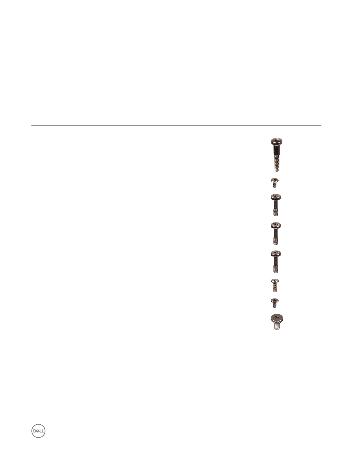
Screw list
The following table provides the list of screws that are used for securing dierent components.
Table 1. Screw list
Component Secured to Screw type Quantity Screw image
Front cover System base M3x18 4
Antenna-cable bracket System board M2x4 1
Antenna-cable bracket System board M3x10 2
Right I/O bracket System board M3x10 1
Left I/O bracket System board M3x10 1
WWAN card WWAN-card bracket M2x6 2
WWAN bracket System board M2x4 1
Earth ground System base M4x7 1
9

After working inside your Edge Gateway
NOTE: Leaving stray or loose screws inside your Edge Gateway may severely damage your Edge Gateway.
1. Replace all screws and ensure that no stray screws remain inside your Edge Gateway.
2. Connect any external devices, peripherals, or cables you removed before working on your Edge Gateway.
3. Connect your Edge Gateway and all attached devices to their electrical outlets.
4. Power on your Edge Gateway.
2
10
Removing the front cover
WARNING: Before working inside your Edge Gateway, read the safety information that shipped with your Edge Gateway
and follow the steps in Before working inside your Edge Gateway. After working inside your Edge Gateway, follow the
steps in After working inside your Edge Gateway. For more safety best practices, see the Regulatory Compliance home
page at www.dell.com/regulatory_compliance.
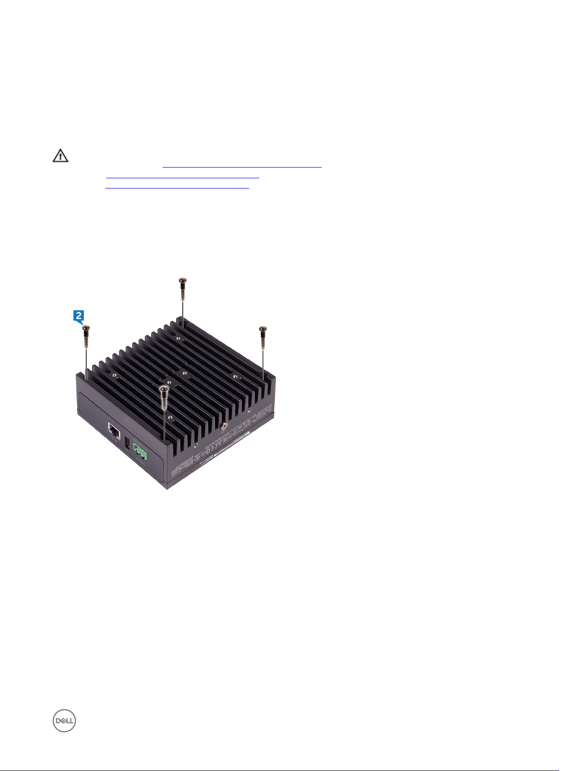
Procedure
1. Turn the system over and place the system on a clean and at surface.
2. Remove the four screws (M3x18) that secure the front cover to the system base.
3
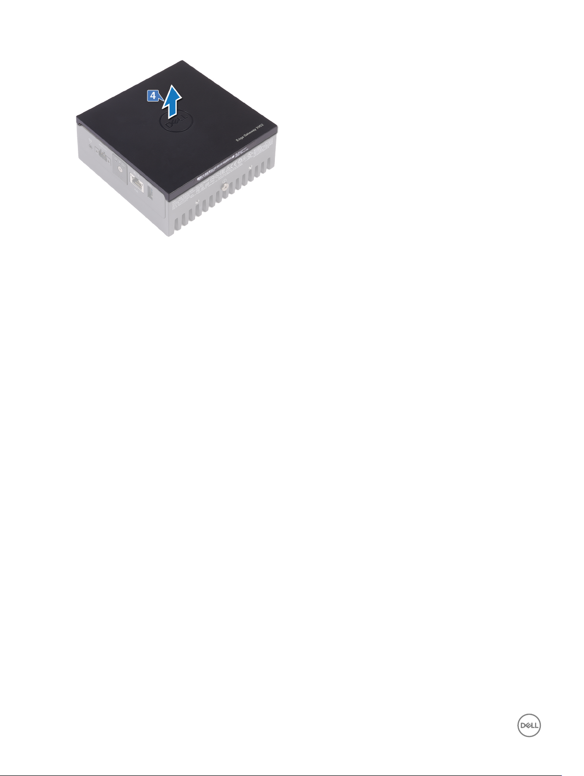
3. Turn the system over.
4. Lift the front cover o the system base.
11
12
Replacing the front cover
WARNING: Before working inside your Edge Gateway, read the safety information that shipped with your Edge Gateway
and follow the steps in Before working inside your Edge Gateway. After working inside your Edge Gateway, follow the
steps in After working inside your Edge Gateway. For more safety best practices, see the Regulatory Compliance home
page at www.dell.com/regulatory_compliance.
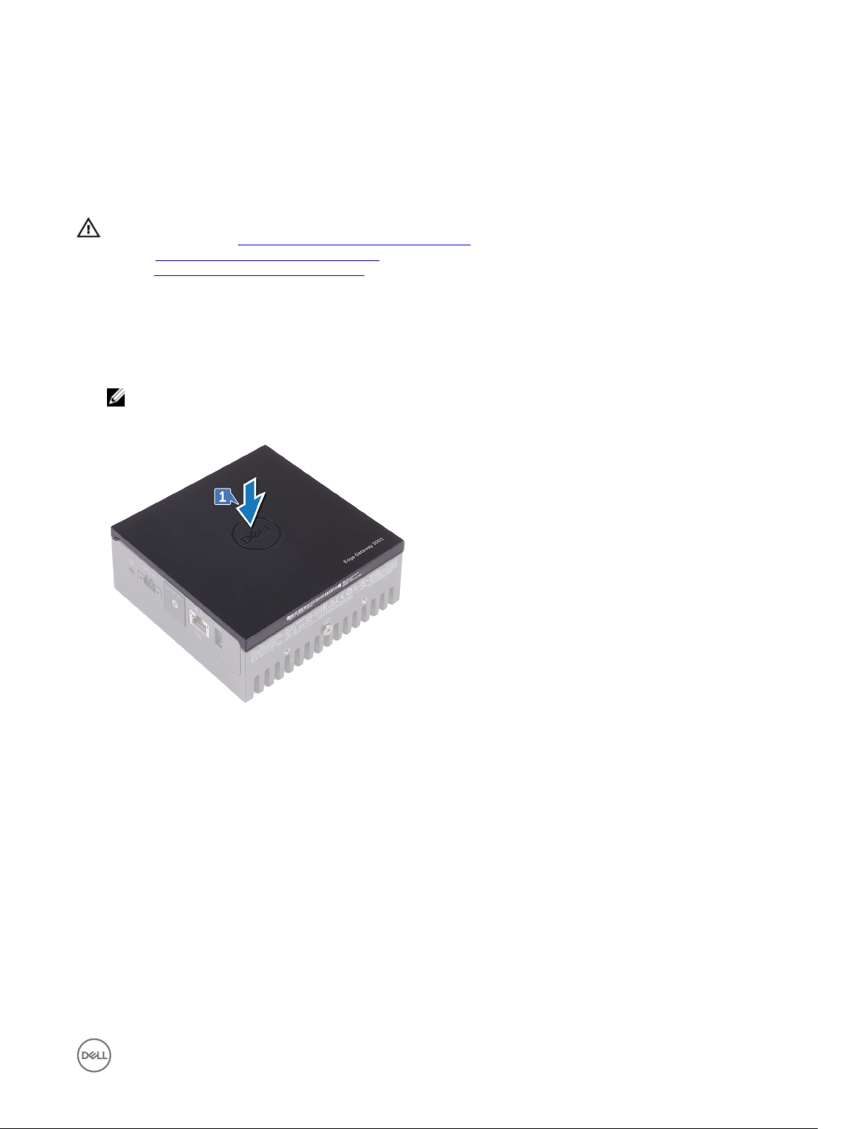
Procedure
1. Place the front cover into the slots on the system base.
NOTE: Note the orientation of the front cover. Align the notch on the front cover with the slots on the system base
and place the front cover.
4
2. Turn the system over.
3. Replace the four screws (M3x18) that secure the front cover to the system base.
13
Removing the antenna-cable bracket
WARNING: Before working inside your Edge Gateway, read the safety information that shipped with your Edge Gateway
and follow the steps in Before working inside your Edge Gateway. After working inside your Edge Gateway, follow the
steps in After working inside your Edge Gateway. For more safety best practices, see the Regulatory Compliance home
page at www.dell.com/regulatory_compliance.
Prerequisites
Remove the front cover.
Procedure
NOTE: The ZigBee cable will be present depending on the conguration ordered.
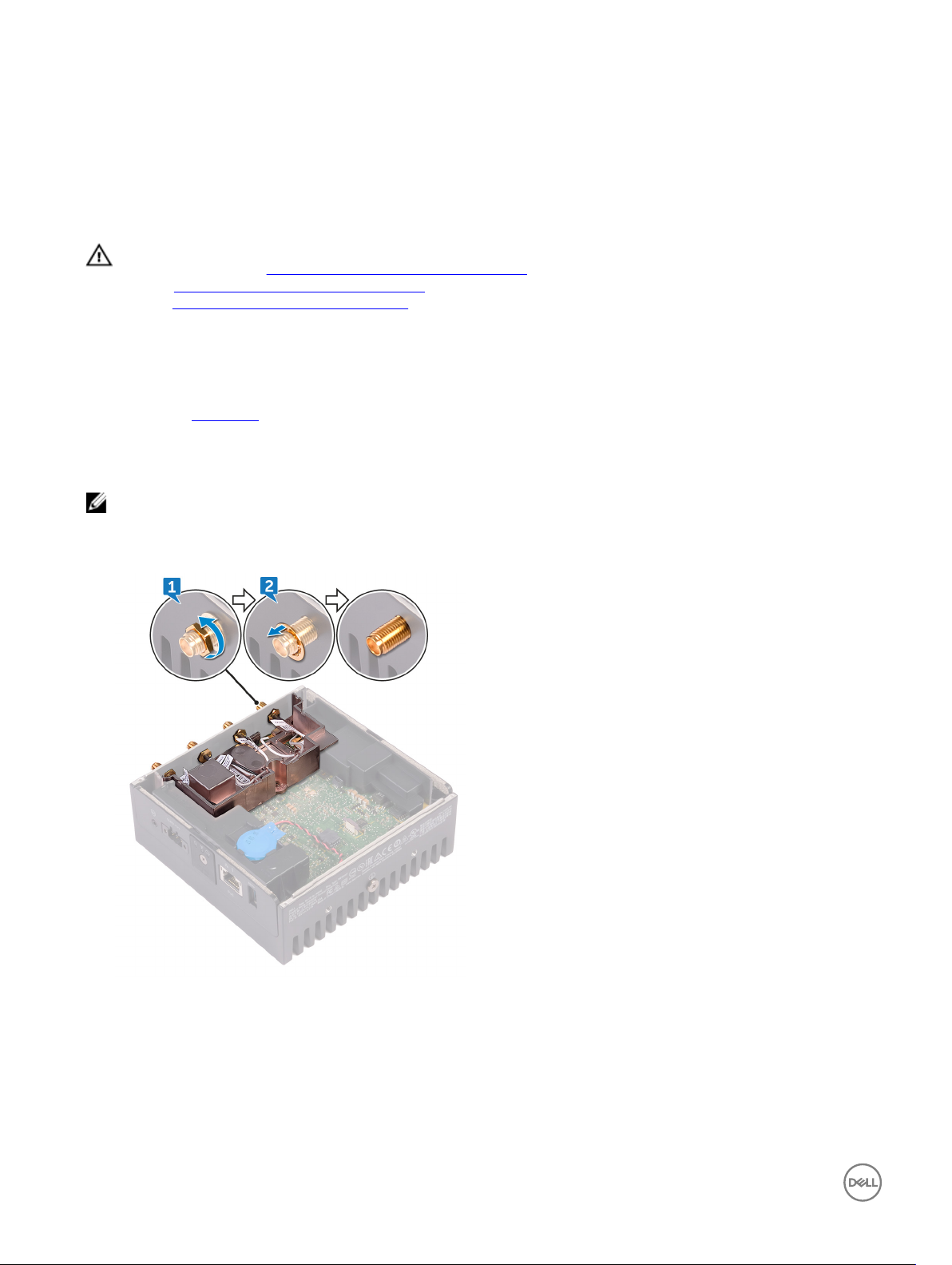
1. Remove the nuts that secure the antenna connectors to the system base.
2. Remove the washers that secure the antenna connectors to the system base.
5
3. Remove the antenna cables from the routing guides on the antenna bracket.
14
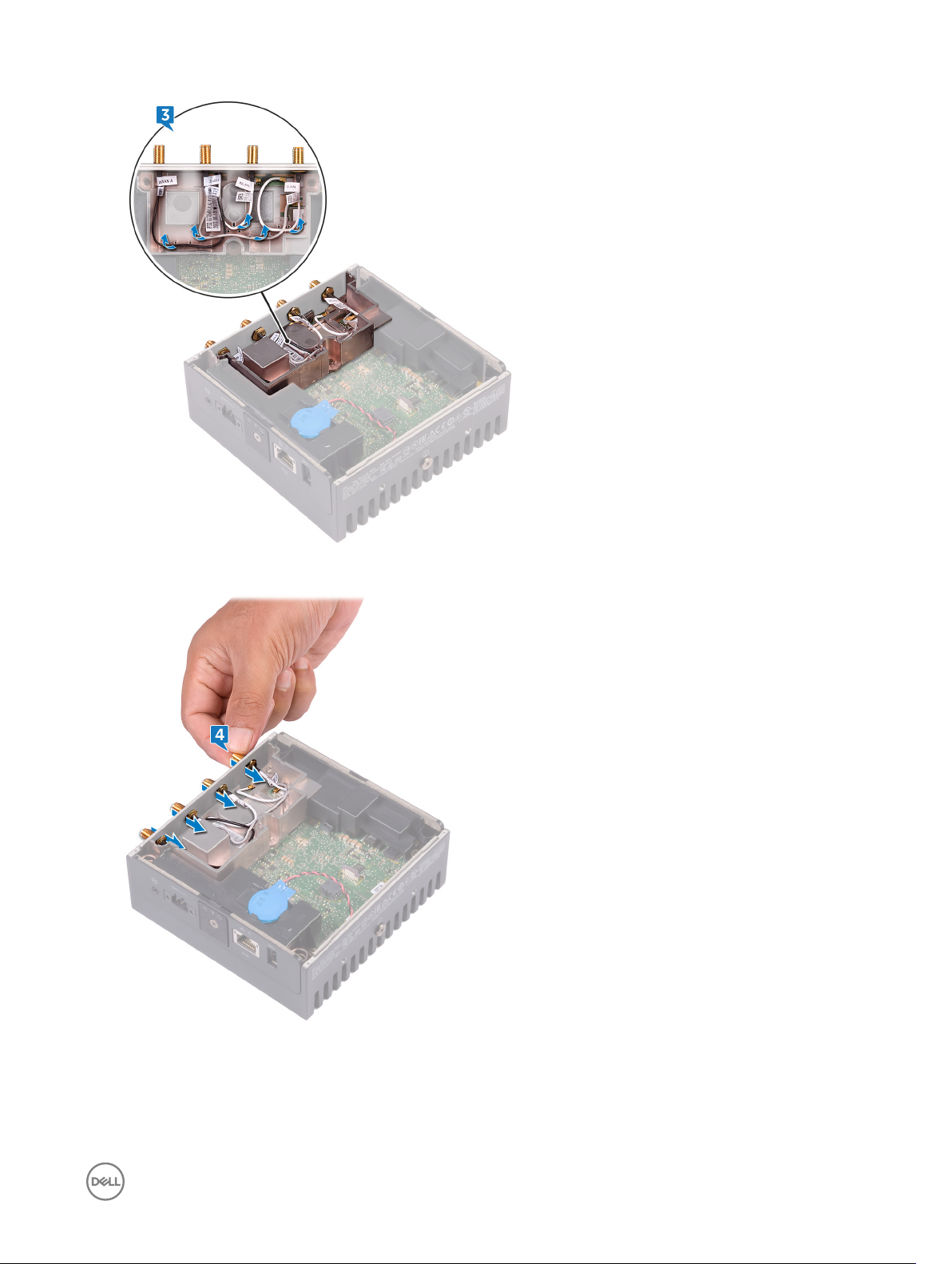
4. Slide and remove the four antenna connectors from the slots on the system base.
5. Remove the two screws (M3x10) that secure the antenna-cable bracket to the system board.
6. Remove the screw (M2x4) that secures the antenna-cable bracket to the system board.
15
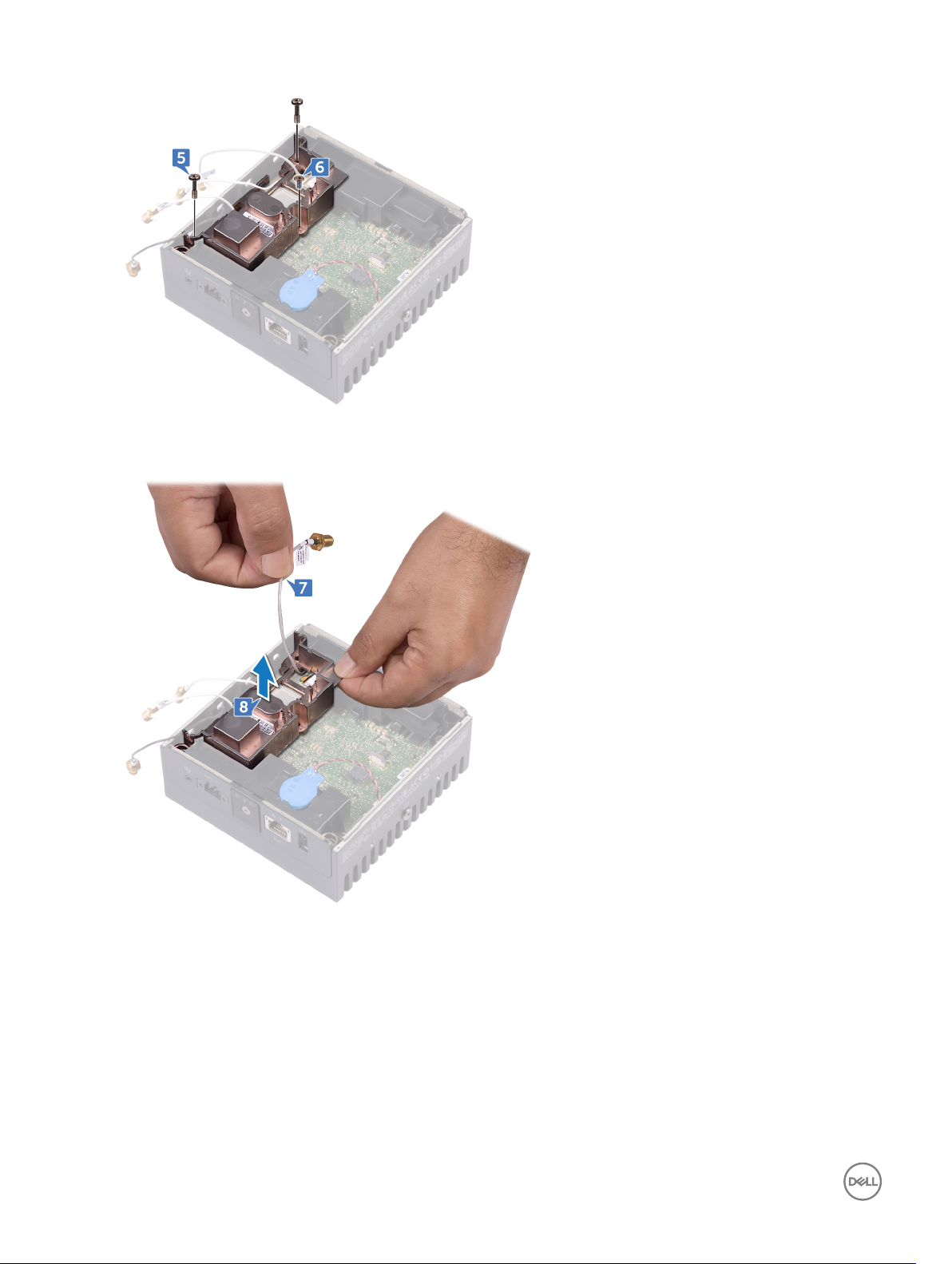
7. Remove the ZigBee cable from the antenna-cable bracket.
8. Lift the antenna-cable bracket o the system board.
16

Replacing the antenna-cable bracket
WARNING: Before working inside your Edge Gateway, read the safety information that shipped with your Edge Gateway
and follow the steps in Before working inside your Edge Gateway. After working inside your Edge Gateway, follow the
steps in After working inside your Edge Gateway. For more safety best practices, see the Regulatory Compliance home
page at www.dell.com/regulatory_compliance.
Procedure
1. Route the ZigBee cable through the antenna-cable bracket.
2. Align the screw hole on the antenna-cable bracket with the screw hole on the system board.
3. Replace the screw (M2x4) that secures antenna-cable bracket to the system board.
4. Replace the two screws (M3x10) that secure the antenna-cable bracket to the system board.
5. Insert the antenna cables through the slots on the system base.
6. Route the antenna cables through the routing guides on the antenna bracket.
7. Replace the washers that secure the antennas to the system base.
8. Replace the nuts that secure the antennas to the system base.
Post-requisites
6
Replace the front cover.
17
Removing the GPS bracket
WARNING: Before working inside your Edge Gateway, read the safety information that shipped with your Edge Gateway
and follow the steps in Before working inside your Edge Gateway. After working inside your Edge Gateway, follow the
steps in After working inside your Edge Gateway. For more safety best practices, see the Regulatory Compliance home
page at www.dell.com/regulatory_compliance.
Prerequisites
Remove the front cover.
Procedure
Lift the GPS bracket o the system board.
7
18

Replacing the GPS bracket
WARNING: Before working inside your Edge Gateway, read the safety information that shipped with your Edge Gateway
and follow the steps in Before working inside your Edge Gateway. After working inside your Edge Gateway, follow the
steps in After working inside your Edge Gateway. For more safety best practices, see the Regulatory Compliance home
page at www.dell.com/regulatory_compliance.
Procedure
Align and place the GPS bracket on the system board.
Post-requisites
Replace the front cover.
8
19
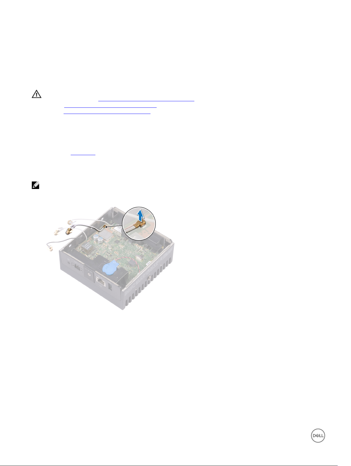
Removing the WLAN cable
WARNING: Before working inside your Edge Gateway, read the safety information that shipped with your Edge Gateway
and follow the steps in Before working inside your Edge Gateway. After working inside your Edge Gateway, follow the
steps in After working inside your Edge Gateway. For more safety best practices, see the Regulatory Compliance home
page at www.dell.com/regulatory_compliance.
Prerequisites
Remove the front cover.
Procedure
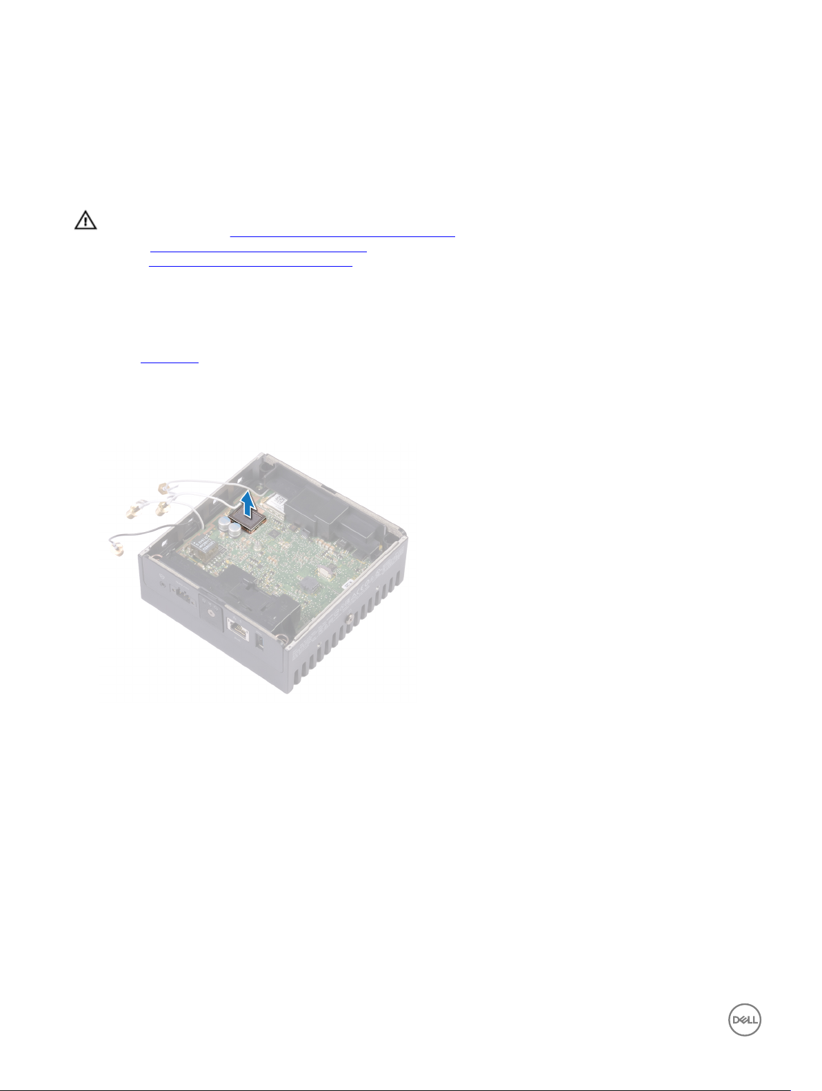
NOTE: The number of antennas and antenna cables varies according to the conguration ordered.
Disconnect the WLAN cable from the system board.
9
20

Replacing the WLAN cable
WARNING: Before working inside your Edge Gateway, read the safety information that shipped with your Edge Gateway
and follow the steps in Before working inside your Edge Gateway. After working inside your Edge Gateway, follow the
steps in After working inside your Edge Gateway. For more safety best practices, see the Regulatory Compliance home
page at www.dell.com/regulatory_compliance.
Procedure
Connect the WLAN cable to the system board.
Post-requisites
Replace the front cover.
10
21

Removing the right-I/O cover
WARNING: Before working inside your Edge Gateway, read the safety information that shipped with your Edge Gateway
and follow the steps in Before working inside your Edge Gateway. After working inside your Edge Gateway, follow the
steps in After working inside your Edge Gateway. For more safety best practices, see the Regulatory Compliance home
page at www.dell.com/regulatory_compliance.
Prerequisites
Remove the front cover.
Procedure
1. Remove the dust caps on the right-I/O ports.
2. Slide and remove the right-I/O cover from the system base.
11
22

Replacing the right-I/O cover
WARNING: Before working inside your Edge Gateway, read the safety information that shipped with your Edge Gateway
and follow the steps in Before working inside your Edge Gateway. After working inside your Edge Gateway, follow the
steps in After working inside your Edge Gateway. For more safety best practices, see the Regulatory Compliance home
page at www.dell.com/regulatory_compliance.
Procedure
1. Place the right-I/O cover on the system base at an angle and snap it into place.
2. Replace dust caps to the right-I/O ports.
Post-requisites
Replace the front cover.
12
23

Removing the coin-cell battery
WARNING: Before working inside your Edge Gateway, read the safety information that shipped with your Edge Gateway
and follow the steps in Before working inside your Edge Gateway. After working inside your Edge Gateway, follow the
steps in After working inside your Edge Gateway. For more safety best practices, see the Regulatory Compliance home
page at www.dell.com/regulatory_compliance.
Prerequisites
Remove the front cover.
Procedure
1. Disconnect the coin-cell battery cable from the system board.
2. Peel o the coin-cell battery from the left-rubber gasket.
13
24

Replacing the coin-cell battery
WARNING: Before working inside your Edge Gateway, read the safety information that shipped with your Edge Gateway
and follow the steps in Before working inside your Edge Gateway. After working inside your Edge Gateway, follow the
steps in After working inside your Edge Gateway. For more safety best practices, see the Regulatory Compliance home
page at www.dell.com/regulatory_compliance.
Procedure
1. Adhere the coin-cell battery on the left-rubber gasket.
2. Connect the coin-cell battery cable to the system board.
Post-requisites
Replace the front cover.
14
25

Removing the left-I/O bracket
WARNING: Before working inside your Edge Gateway, read the safety information that shipped with your Edge Gateway
and follow the steps in Before working inside your Edge Gateway. After working inside your Edge Gateway, follow the
steps in After working inside your Edge Gateway. For more safety best practices, see the Regulatory Compliance home
page at www.dell.com/regulatory_compliance.
Prerequisites
1. Remove the front cover.
2. Remove the antenna-cable bracket.
3. Remove the coin-cell battery.
Procedure
1. Remove the screw (M3x10) that secures the left-I/O bracket to the system board.
2. Lift the left-I/O bracket o the system board.
15
26

Replacing the left-I/O bracket
WARNING: Before working inside your Edge Gateway, read the safety information that shipped with your Edge Gateway
and follow the steps in Before working inside your Edge Gateway. After working inside your Edge Gateway, follow the
steps in After working inside your Edge Gateway. For more safety best practices, see the Regulatory Compliance home
page at www.dell.com/regulatory_compliance.
Procedure
1. Align the left-I/O bracket on the left-I/O ports and place the left-I/O bracket on the system board.
2. Replace the screw (M3x10) that secures the left-I/O bracket to the system board.
Post-requisites
1. Replace the coin-cell battery.
2. Replace the antenna-cable bracket.
3. Replace the front cover.
16
27

Removing the status-light lens
WARNING: Before working inside your Edge Gateway, read the safety information that shipped with your Edge Gateway
and follow the steps in Before working inside your Edge Gateway. After working inside your Edge Gateway, follow the
steps in After working inside your Edge Gateway. For more safety best practices, see the Regulatory Compliance home
page at www.dell.com/regulatory_compliance.
Prerequisites
1. Remove the front cover.
2. Remove the antenna-cable bracket.
3. Remove the left-I/O bracket.
Procedure
1. Slide the left-I/O cover at an angle from the system base.
17
2. Lift the status-light lens o the left-rubber gasket.
28

Replacing the status-light lens
WARNING: Before working inside your Edge Gateway, read the safety information that shipped with your Edge Gateway
and follow the steps in Before working inside your Edge Gateway. After working inside your Edge Gateway, follow the
steps in After working inside your Edge Gateway. For more safety best practices, see the Regulatory Compliance home
page at www.dell.com/regulatory_compliance.
Procedure
1. Place the status-light lens on the rubber gasket.
2. Slide the left-I/O cover to the system base.
Post-requisites
1. Replace the left-I/O bracket.
2. Replace the antenna-cable bracket.
3. Replace the front cover.
18
29

Removing the right-I/O bracket
WARNING: Before working inside your Edge Gateway, read the safety information that shipped with your Edge Gateway
and follow the steps in Before working inside your Edge Gateway. After working inside your Edge Gateway, follow the
steps in After working inside your Edge Gateway. For more safety best practices, see the Regulatory Compliance home
page at www.dell.com/regulatory_compliance.
Prerequisites
1. Remove the top cover.
2. Remove the antenna-cable bracket.
3. Remove the right-I/O cover.
Procedure
1. Remove the screw (M3x10) that secures the right-I/O bracket to the system board.
2. Slide and release the tabs on the right-I/O bracket from the system board.
3. Lift the right-I/O bracket o the system board.
19
30

Replacing the right-I/O bracket
WARNING: Before working inside your Edge Gateway, read the safety information that shipped with your Edge Gateway
and follow the steps in Before working inside your Edge Gateway. After working inside your Edge Gateway, follow the
steps in After working inside your Edge Gateway. For more safety best practices, see the Regulatory Compliance home
page at www.dell.com/regulatory_compliance.
Procedure
1. Place the right-I/O bracket on the system board.
2. Align the tabs on the right-I/O bracket to the system board and snap the right I/O bracket into place.
3. Replace the screw (M3x10) that secures the right-I/O bracket to the system board.
Post-requisites
1. Replace the right-I/O cover.
2. Replace the antenna-cable bracket.
3. Replace the front cover.
20
31

Removing the ZigBee cable
WARNING: Before working inside your Edge Gateway, read the safety information that shipped with your Edge Gateway
and follow the steps in Before working inside your Edge Gateway. After working inside your Edge Gateway, follow the
steps in After working inside your Edge Gateway. For more safety best practices, see the Regulatory Compliance home
page at www.dell.com/regulatory_compliance.
Prerequisites
NOTE: Depending on the conguration ordered, the ZigBee antenna and cable may not be available.
1. Remove the front cover.
2. Remove the antenna-cable bracket.
3. Remove the right-I/O cover.
4. Remove the right-I/O bracket.
Procedure
Remove the ZigBee cable from the system board.
21
32

Replacing the ZigBee cable
WARNING: Before working inside your Edge Gateway, read the safety information that shipped with your Edge Gateway
and follow the steps in Before working inside your Edge Gateway. After working inside your Edge Gateway, follow the
steps in After working inside your Edge Gateway. For more safety best practices, see the Regulatory Compliance home
page at www.dell.com/regulatory_compliance.
Procedure
Connect the ZigBee cable to the system board.
Post-requisites
1. Replace the right-I/O bracket.
2. Replace the right-I/O cover.
3. Replace the antenna-cable bracket.
4. Replace the front cover.
22
33

Removing the WWAN card
WARNING: Before working inside your Edge Gateway, read the safety information that shipped with your Edge Gateway
and follow the steps in Before working inside your Edge Gateway. After working inside your Edge Gateway, follow the
steps in After working inside your Edge Gateway. For more safety best practices, see the Regulatory Compliance home
page at www.dell.com/regulatory_compliance.
Prerequisites
NOTE: Depending on the conguration ordered, the WWAN card and bracket may not be available.
1. Remove the front cover.
2. Remove the antenna-cable bracket.
3. Remove the coin-cell battery.
4. Remove the right-I/O cover.
5. Remove the right-I/O bracket.
6. Remove the left-I/O bracket.
Procedure
23
1. Slide the left-I/O cover from the system base.
2. Lift the system board o the system base.
34

3. Turn the system board over.
4. Remove the two screws (M2x6) that secure the WWAN-card bracket to the WWAN card and lift the WWAN-card bracket o
the WWAN card.
5. Peel the tape that secures the WWAN antenna cables and disconnect the WWAN antenna cables from the WWAN card.
6. Slide and remove the WWAN card o the WWAN-card slot.
35

Replacing the WWAN card
WARNING: Before working inside your Edge Gateway, read the safety information that shipped with your Edge Gateway
and follow the steps in Before working inside your Edge Gateway. After working inside your Edge Gateway, follow the
steps in After working inside your Edge Gateway. For more safety best practices, see the Regulatory Compliance home
page at www.dell.com/regulatory_compliance.
Procedure
NOTE: To avoid damage to the WWAN card, do not place any cables under it.
1. Align the notch on the WWAN card to the tab on the WWAN-card slot.
2. Insert the WWAN card at an angle into the WWAN-card slot.
3. Connect the WWAN antenna cables to the WWAN card.
4. Adhere the tape that secures the antenna cables.
5. Align the screw holes on the WWAN-card bracket with the screw holes on the WWAN card.
6. Replace the two screws (M2x6) that secure the WWAN-card bracket to the WWAN card.
7. Turn the system board over.
8. Align and place the system board on the system base.
9. Slide the left-I/O cover to the system base.
24
Post-requisites
1. Replace the left-I/O bracket.
2. Replace the right-I/O bracket.
3. Replace the right-I/O cover.
4. Replace the coin-cell battery.
5. Replace the antenna-cable bracket.
6. Replace the front cover.
36

Removing the WWAN bracket
WARNING: Before working inside your Edge Gateway, read the safety information that shipped with your Edge Gateway
and follow the steps in Before working inside your Edge Gateway. After working inside your Edge Gateway, follow the
steps in After working inside your Edge Gateway. For more safety best practices, see the Regulatory Compliance home
page at www.dell.com/regulatory_compliance.
Prerequisites
NOTE: Depending on the conguration ordered, the WWAN card and bracket may not be available.
1. Remove the front cover.
2. Remove the antenna-cable bracket.
3. Remove the coin-cell battery.
4. Remove the right-I/O cover.
5. Remove the right-I/O bracket.
6. Remove the left-I/O bracket.
7. Remove the WWAN card.
25
Procedure
1. Remove the screw (M2x4) that secures the WWAN bracket to the system board.
2. Lift the WWAN bracket o the system board.
37

Replacing the WWAN bracket
WARNING: Before working inside your Edge Gateway, read the safety information that shipped with your Edge Gateway
and follow the steps in Before working inside your Edge Gateway. After working inside your Edge Gateway, follow the
steps in After working inside your Edge Gateway. For more safety best practices, see the Regulatory Compliance home
page at www.dell.com/regulatory_compliance.
Procedure
1. Align the screw hole on the WWAN bracket with the screw hole on the system board.
2. Replace the screw (M2x4) that secures the WWAN bracket to the system board.
Post-requisites
1. Replace the left-I/O bracket.
2. Replace the right-I/O bracket.
3. Replace the right-I/O cover.
4. Replace the antenna-cable bracket.
5. Replace the front cover.
6. Replace the coin-cell battery.
7. Replace the WWAN card.
26
38

Removing the right-rubber gasket
WARNING: Before working inside your Edge Gateway, read the safety information that shipped with your Edge Gateway
and follow the steps in Before working inside your Edge Gateway. After working inside your Edge Gateway, follow the
steps in After working inside your Edge Gateway. For more safety best practices, see the Regulatory Compliance home
page at www.dell.com/regulatory_compliance.
Prerequisites
1. Remove the front cover.
2. Remove the antenna-cable bracket.
3. Remove the right-I/O cover.
4. Remove the right-I/O bracket.
Procedure
1. Gently release the ports on the system board from the slots on the right-rubber gasket.
2. Slide and lift the right-rubber gasket o the system board.
27
39

Replacing the right-rubber gasket
WARNING: Before working inside your Edge Gateway, read the safety information that shipped with your Edge Gateway
and follow the steps in Before working inside your Edge Gateway. After working inside your Edge Gateway, follow the
steps in After working inside your Edge Gateway. For more safety best practices, see the Regulatory Compliance home
page at www.dell.com/regulatory_compliance.
Procedure
1. Slide the ports on the system board into the slots on the right-rubber gasket.
2. Place the right-rubber gasket on the system board.
Post-requisites
1. Replace the right-I/O bracket.
2. Replace the right-I/O cover.
3. Replace the antenna-cable bracket.
4. Replace the front cover.
28
40

Removing the left-rubber gasket
WARNING: Before working inside your Edge Gateway, read the safety information that shipped with your Edge Gateway
and follow the steps in Before working inside your Edge Gateway. After working inside your Edge Gateway, follow the
steps in After working inside your Edge Gateway. For more safety best practices, see the Regulatory Compliance home
page at www.dell.com/regulatory_compliance.
Prerequisites
1. Remove the front cover.
2. Remove the antenna-cable bracket.
3. Remove the coin-cell battery.
4. Remove the left-I/O bracket.
5. Remove the status-light lens.
Procedure
1. Slide the left-I/O cover from the system base.
29
2. Gently release the ports on the system board from the slots on the left-rubber gasket.
3. Slide and lift the left-rubber gasket o the system board.
41

42

Replacing the left-rubber gasket
WARNING: Before working inside your Edge Gateway, read the safety information that shipped with your Edge Gateway
and follow the steps in Before working inside your Edge Gateway. After working inside your Edge Gateway, follow the
steps in After working inside your Edge Gateway. For more safety best practices, see the Regulatory Compliance home
page at www.dell.com/regulatory_compliance.
Procedure
1. Slide the ports on the system board into the slots on the left-rubber gasket.
2. Place the left-rubber gasket on the system board.
3. Slide the left-I/O cover to the system base.
Post-requisites
1. Replace the status-light lens.
2. Replace the left-I/O bracket.
3. Replace the coin-cell battery.
4. Replace the antenna-cable bracket.
5. Replace the front cover.
30
43

Removing the system board
WARNING: Before working inside your Edge Gateway, read the safety information that shipped with your Edge Gateway
and follow the steps in Before working inside your Edge Gateway. After working inside your Edge Gateway, follow the
steps in After working inside your Edge Gateway. For more safety best practices, see the Regulatory Compliance home
page at www.dell.com/regulatory_compliance.
Prerequisites
1. Remove the front cover.
2. Remove the antenna-cable bracket.
3. Remove the WLAN cable.
4. Remove the coin-cell battery.
5. Remove the right-I/O cover.
6. Remove the right-I/O bracket.
7. Remove the left-I/O bracket.
8. Remove the status-light lens.
9. Remove the ZigBee cable.
10. Remove the left-rubber gasket.
11. Remove the right-rubber gasket.
31
Procedure
1. Lift the system board o the system base.
2. Turn the system board over.
3. Remove the WWAN card.
4. Remove the WWAN bracket.
5. Remove the WLAN bracket
6. Remove the thermal pad from the system base.
44

45

Replacing the system board
WARNING: Before working inside your Edge Gateway, read the safety information that shipped with your Edge Gateway
and follow the steps in Before working inside your Edge Gateway. After working inside your Edge Gateway, follow the
steps in After working inside your Edge Gateway. For more safety best practices, see the Regulatory Compliance home
page at www.dell.com/regulatory_compliance.
Procedure
1. Replace the thermal pad on the system base.
32
2. Replace the WLAN bracket.
3. Replace the WWAN bracket.
4. Replace the WWAN card.
5. Turn the system board over.
6. Align and place the system board on the system base.
Post-requisites
1. Replace the right-rubber gasket.
2. Replace the left-rubber gasket.
3. Replace the ZigBee cable.
4. Replace the status-light lens.
5. Replace the left-I/O bracket.
6. Replace the right-I/O bracket.
7. Replace the right-I/O cover.
8. Replace the coin-cell battery.
9. Replace the WLAN cable.
10. Replace the antenna-cable bracket.
11. Replace the front cover.
46

Removing the WLAN bracket
WARNING: Before working inside your Edge Gateway, read the safety information that shipped with your Edge Gateway
and follow the steps in Before working inside your Edge Gateway. After working inside your Edge Gateway, follow the
steps in After working inside your Edge Gateway. For more safety best practices, see the Regulatory Compliance home
page at www.dell.com/regulatory_compliance.
Prerequisites
1. Remove the front cover.
2. Remove the antenna-cable bracket.
3. Remove the coin-cell battery.
4. Remove the right-I/O cover.
5. Remove the right-I/O bracket.
6. Remove the left-I/O bracket.
Procedure
1. Slide the left-I/O cover from the system base.
33
2. Lift the system board o the system base.
47

3. Turn the system board over.
4. Lift the WLAN bracket o the system board.
48

Replacing the WLAN bracket
WARNING: Before working inside your Edge Gateway, read the safety information that shipped with your Edge Gateway
and follow the steps in Before working inside your Edge Gateway. After working inside your Edge Gateway, follow the
steps in After working inside your Edge Gateway. For more safety best practices, see the Regulatory Compliance home
page at www.dell.com/regulatory_compliance.
Procedure
1. Align and place the WLAN bracket on the system board.
2. Turn the system board over.
3. Align and place the system board on the system base.
4. Slide the left-I/O cover to the system base.
Post-requisites
1. Replace the left-I/O bracket.
2. Replace the right-I/O bracket.
3. Replace the right-I/O cover.
4. Replace the coin-cell battery.
5. Replace the antenna-cable bracket.
6. Replace the front cover.
34
49

Removing the left-I/O cover
WARNING: Before working inside your Edge Gateway, read the safety information that shipped with your Edge Gateway
and follow the steps in Before working inside your Edge Gateway. After working inside your Edge Gateway, follow the
steps in After working inside your Edge Gateway. For more safety best practices, see the Regulatory Compliance home
page at www.dell.com/regulatory_compliance.
Prerequisites
1. Remove the front cover.
2. Remove the antenna-cable bracket.
3. Remove the WLAN cable.
4. Remove the coin-cell battery.
5. Remove the right-I/O cover.
6. Remove the right-I/O bracket.
7. Remove the left-I/O bracket.
8. Remove the ZigBee cable.
9. Remove the right-rubber gasket.
10. Remove the status-light lens.
11. Remove the left-rubber gasket.
12. Remove the system board.
35
Procedure
1. Remove the dust caps on the left-I/O ports.
2. Slide the left-I/O cover away from the system base.
50

Replacing the left-I/O cover
WARNING: Before working inside your Edge Gateway, read the safety information that shipped with your Edge Gateway
and follow the steps in Before working inside your Edge Gateway. After working inside your Edge Gateway, follow the
steps in After working inside your Edge Gateway. For more safety best practices, see the Regulatory Compliance home
page at www.dell.com/regulatory_compliance.
Procedure
1. Insert the tab on the left-I/O cover to the slot on the system base.
2. Slide the left-I/O cover onto the system base at an angle and snap it into place.
3. Replace the dust caps to the left-I/O ports.
Post-requisites
1. Replace the system board.
2. Replace the left-rubber gasket.
3. Replace the status-light lens.
4. Replace the right-rubber gasket.
5. Replace the ZigBee cable.
6. Replace the left-I/O bracket.
7. Replace the right-I/O bracket.
8. Replace the right-I/O cover.
9. Replace the coin-cell battery.
10. Replace the WLAN cable.
11. Replace the antenna-cable bracket.
12. Replace the front cover.
36
51

Removing the access door
WARNING: Before working inside your Edge Gateway, read the safety information that shipped with your Edge Gateway
and follow the steps in Before working inside your Edge Gateway. After working inside your Edge Gateway, follow the
steps in After working inside your Edge Gateway. For more safety best practices, see the Regulatory Compliance home
page at www.dell.com/regulatory_compliance.
Prerequisites
1. Remove the front cover.
2. Remove the antenna-cable bracket.
3. Remove the WLAN cable.
4. Remove the coin-cell battery.
5. Remove the right-I/O cover.
6. Remove the right-I/O bracket.
7. Remove the left-I/O bracket.
8. Remove the ZigBee cable.
9. Remove the right-rubber gasket.
10. Remove the status-light lens.
11. Remove the left-rubber gasket.
12. Remove the system board.
13. Remove the left-I/O cover.
37
Procedure
1. Loosen the captive screw that secures access door to the left-I/O cover.
2. Remove the access door from the slot on the left-I/O cover.
52

Replacing the access door
WARNING: Before working inside your Edge Gateway, read the safety information that shipped with your Edge Gateway
and follow the steps in Before working inside your Edge Gateway. After working inside your Edge Gateway, follow the
steps in After working inside your Edge Gateway. For more safety best practices, see the Regulatory Compliance home
page at www.dell.com/regulatory_compliance.
Procedure
1. Place the access door in the slot on the left-I/O cover.
2. Tighten the captive screw that secures access door to the left-I/O cover.
Post-requisites
1. Replace the left-I/O cover.
2. Replace the system board.
3. Replace the left-rubber gasket.
4. Replace the status-light lens.
5. Replace the right-rubber gasket.
6. Replace the ZigBee cable.
7. Replace the left-I/O bracket.
8. Replace the right-I/O bracket.
9. Replace the right-I/O cover.
10. Replace the coin-cell battery.
11. Replace the WLAN cable.
12. Replace the antenna-cable bracket.
13. Replace the front cover.
38
53

Removing the loop-back cable
WARNING: Before working inside your Edge Gateway, read the safety information that shipped with your Edge Gateway
and follow the steps in Before working inside your Edge Gateway. After working inside your Edge Gateway, follow the
steps in After working inside your Edge Gateway. For more safety best practices, see the Regulatory Compliance home
page at www.dell.com/regulatory_compliance.
Prerequisites
1. Remove the front cover.
2. Remove the antenna-cable bracket.
3. Remove the coin-cell battery.
4. Remove the right-I/O cover.
5. Remove the right-I/O bracket.
6. Remove the left-I/O bracket.
Procedure
1. Slide the left-I/O cover from the system base.
39
2. Lift the system board o the system base.
54

3. Disconnect the loop-back cable from the system board.
4. Turn the system board over.
5. Lift the WLAN bracket from the system board.
6. Disconnect the loop-back cable from the system board.
55

56

Replacing the loop-back cable
WARNING: Before working inside your Edge Gateway, read the safety information that shipped with your Edge Gateway
and follow the steps in Before working inside your Edge Gateway. After working inside your Edge Gateway, follow the
steps in After working inside your Edge Gateway. For more safety best practices, see the Regulatory Compliance home
page at www.dell.com/regulatory_compliance.
Procedure
1. Connect the loop-back cable to the system board.
2. Place the WLAN bracket on the system board.
3. Turn the system board over.
4. Connect the loop-back cable to the system board.
5. Align and place the system board on the system base.
6. Slide the left-I/O cover to the system base.
Post-requisites
1. Replace the left-I/O bracket.
2. Replace the right-I/O bracket.
3. Replace the right-I/O cover.
4. Replace the coin-cell battery.
5. Replace the antenna-cable bracket.
6. Replace the front cover.
40
57

41
Accessing and updating BIOS
Accessing BIOS settings
Use Dell Command | Congure (DCC) to access BIOS settings
Dell Command | Congure (DCC) is a factory-installed application in the Edge Gateway that helps to congure the BIOS settings. It
consists of a Command Line Interface (CLI) to congure various BIOS features. For more information about DCC, see
www.dell.com/dellclientcommandsuitemanuals.
• On the connected computer running Windows, click Start → All Programs → Command Congure → Dell Command |
Congure Wizard
• On the connected computer running Ubuntu Core, access Dell Command | Congure using the command dcc.cctk
For more information on how to use the Dell Command | Congure application, see the Dell Command | Congure Installation Guide
and User's Guide at www.dell.com/dellclientcommandsuitemanuals.
For more information about BIOS settings on the Edge Gateway, see Default BIOS settings
Use Edge Device Manager (EDM) to access BIOS settings
Edge Device Manager (EDM) enables you to perform remote management and system conguration. By using the EDM cloud
console, you can view and congure the BIOS settings. For more information about the EDM, see www.dell.com/support/
home/us/en/19/product-support/product/wyse-cloud-client-manager/research.
Entering BIOS setup during POST
NOTE: These steps are applicable only to the Edge Gateway 3003.
1. Connect a display, keyboard and mouse to the system.
2. Power on the Edge Gateway.
3. During POST, when the Dell logo is displayed, watch for the F2 prompt to appear, and then press F2 immediately.
Updating BIOS
NOTE: Download the latest BIOS le from dell.com/support/home/us/en/19/product-support/product/dell-edge-
gateway-3000-series/drivers/.
Select one of these options to update the BIOS on the Edge Gateway.
• Using the USB invocation script
NOTE: Dell recommends the use of the USB invocation script to update the BIOS.
• (Edge Gateway 3003 only) Flashing the BIOS from a USB ash drive
• Updating the BIOS on a Windows system
• Using UEFI capsule update on an Ubuntu system
• Dell Command | Congure (DCC)
58

• Edge Device Manager (EDM)
Using the USB invocation script
The Edge Gateway 3000 Series come in headless congurations—that is, congurations without any video output. Certain basic
system administration tasks traditionally accomplished by the BIOS Setup program are not possible without video. Hence, to perform
these system administration tasks, Edge Gateways contain a facility for running an invocation script of BIOS commands from a USB
ash drive.
For more information about USB invocation script, see the Edge Gateway USB script utility User's Guide at www.dell.com/support/
home/us/en/19/product-support/product/dell-edge-gateway-3000-series/drivers/.
Flashing the BIOS from a USB ash drive
Prerequisites
• BIOS le. Download the le from www.dell.com/support.
• A blank USB 2.0 or 3.0 USB ash drive with at least 4 GB of storage space.
Follow these steps to update the BIOS:
1. Power o the Edge Gateway.
2. Copy the BIOS update le to a USB ash drive.
3. Insert the USB ash drive in one of the available USB ports on the Edge Gateway.
4. Power on the Edge Gateway.
5. Press F12 when the system is starting up to enter the one-time boot screen.
6. On the one-time boot screen, choose Flash the BIOS.
7. In the next screen, select the BIOS le on the USB ash drive.
8. Start the ash process.
Updating the BIOS on a Windows system
Follow these steps to update the BIOS:
1. After connecting to the Edge Gateway.
NOTE: Connect and login to the Edge Gateway with one these options:
• Remote system conguration
• Direct system conguration (only for Edge Gateway 3003)
• Static IP system conguration (only for Edge Gateway 3002 and 3003)
2. Go to www.dell.com/support.
3. Click Product support, enter the Service Tag of your system, and then click Submit.
NOTE: If you do not have the Service Tag, use the auto-detect feature or manually browse to your system model.
4. Click Drivers & downloads.
5. Select the operating system installed on your system.
6. Scroll down the page and expand BIOS.
7. Click Download to download the latest version of the BIOS for your system.
8. After the download is complete, navigate to the folder where you saved the BIOS le.
9. Double-click the BIOS update le icon and follow the instructions on the screen.
Using UEFI capsule update on an Ubuntu system
The fwupgmgr tool or commands are used to update the UEFI BIOS on the system. The UEFI BIOS for this platform is released
through online Linux Vendor File System (LVFS) based methods
59

Dell recommends that you enable the UEFI Capsule update by default so that it is running in the background to keep the system
BIOS up to date.
NOTE: For more information about fwupd commands, see www.fwupd.org/users.
Without an internet connection
1. Download the latest .cab le from secure-lvfs.rhcloud.com/lvfs/devicelist.
2. Check the current BIOS details.
$ sudo uefi-fw-tools.fwupdmgr get-devices
3. Copy the rmware.cab le to /root/snap/ue-fw-tools/common/ folder.
$ sudo cp firmware.cab /root/snap/uefi-fw-tools/common/
4. Check the details of the BIOS from the .cab le.
$ sudo uefi-fw-tools.fwupdmgr get-details [Full path of firmware.cab]
5. Apply the update.
$ sudo uefi-fw-tools.fwupdmgr install [Full path of firmware.cab] -v --allow-older -allow-reinstall
6. Check the EFI boot details.
$ sudo efibootmgr –v
7. Restart the system.
$ sudo reboot
With an internet connection
1. Connect and login to the Edge Gateway.
NOTE: Connect and login to the Edge Gateway with one these options:
• Remote system conguration (only for Edge Gateway 3001 and 3002)
• Direct system conguration (only for Edge Gateway 3003)
• Static IP conguration (only for Edge Gateway 3002 and 3003)
2. Check the current BIOS details.
$sudo uefi-fw-tools.fwupdmgr get-devices
3. Check if the update is available from LVFS service.
$sudo uefi-fw-tools.fwupdmgr refresh
4. Download the BIOS from the www.dell.com/support.
$sudo uefi-fw-tools.fwupdmgr get-updates
5. Apply the update.
$sudo uefi-fw-tools.fwupdmgr update -v --allow-older --allow-reinstall
6. Check the EFI boot details.
$ sudo efibootmgr –v
7. Restart the system.
$ sudo reboot
Dell Command | Congure (DCC)
Use DCC to update and congure the BIOS settings.
For more information on how to use DCC, see the DCC Installation Guide and User's Guide at www.dell.com/
dellclientcommandsuitemanuals.
For more information about BIOS settings on the Edge Gateway, see Default BIOS settings.
Edge Device Manager (EDM)
BIOS can be updated remotely through the EDM console connected to a remote system.
60

For more information about EDM, see www.dell.com/support/home/us/en/19/product-support/product/wyse-cloud-client-
manager/research.
Default BIOS settings
General (BIOS level 1)
Table 2. General (BIOS level 1)
BIOS level 2 BIOS level 3 Item Default value
System Information
System Information BIOS Version Not applicable
Service Tag Not applicable
Asset Tag Not applicable
Ownership Tag Not applicable
Manufacturing Date Not applicable
Ownership Date Not applicable
Express Service Code Not applicable
Memory Information Memory Installed Not applicable
Memory Available Not applicable
Memory Speed Not applicable
Memory Channel Mode Not applicable
Memory Technology Not applicable
Processor Information Processor Type Not applicable
Core Count Not applicable
Processor ID Not applicable
Current Clock Speed Not applicable
Minimum Clock Speed Not applicable
Maximum Clock Speed Not applicable
Processor L2 Cache Not applicable
Processor L3 Cache Not applicable
HT Capable Not applicable
64-Bit Technology Not applicable
Device Information eMMC Drive Not applicable
61

BIOS level 2 BIOS level 3 Item Default value
LOM MAC Address Not applicable
LOM2 MAC Address Not applicable
Video Controller Not applicable
Video BIOS Version Not applicable
Wi-Fi Device Not applicable
Celluar Device Not applicable
Bluetooth Device Not applicable
Boot Sequence Boot Sequence Boot Sequence - Depends on
installed boot devices
Boot List option [Legacy/UEFI] UEFI
Advanced Boot Options Advanced Boot Options Enable Legacy Option ROMs
[Enable/Disable]
Date/Time Date/Time Date [MM/DD/YY] Not applicable
Time [HH:MM:SS A/P] Not applicable
Depends on installed boot
devices
Enabled
System conguration (BIOS level 1)
Table 3. System conguration (BIOS level 1)
BIOS level 2 BIOS level 3 Item Default value
Integrated NIC Integrated NIC Enable UEFI Network Stack
[Enable/Disable]
[Disabled, Enabled, Enabled w/
PXE]
Integrated NIC 2 [Disabled, Enabled] Enabled
Enabled
Enabled w/PXE
Serial Port1 [Disable, RS232, RS-485 HALF
DUPLEX, RS-485/422 FULL
DUPLEX]
Serial Port2 [Disable, RS232, RS-485 HALF
DUPLEX, RS-485/422 FULL
DUPLEX]
USB Conguration USB Conguration Enable Boot Support [Enable/
Disable]
Enable USB 3.0 Controller
[Enable/Disable]
Enable USB Port1 [Enable/
Disable]
62
RS232
RS232
Enabled
Enabled
Enabled

BIOS level 2 BIOS level 3 Item Default value
Enable USB Port2 [Enable/
Disable]
Audio Enable Audio [Enable/Disable] Enabled
Enabled
Miscellaneous Devices Enable WWAN [Enable/
Disable]
Enable WLAN/Bluetooth
[Enable/Disable]
Enable CANBus [Enable/
Disable]
Enable ZigBee [Enable/Disable] Enabled
Enable Dedicated GPS Radio
[Enable/Disable]
Enable MEMs Sensor [Enable/
Disable]
Watchdog Timer Support Watchdog Timer Support Enable Watchdog Timer
[Enable/Disable]
Enabled
Enabled
Enabled
Enabled
Enabled
Disabled
Security (BIOS level 1)
Table 4. Security (BIOS level 1)
BIOS level 2 BIOS level 3 Item Default value
Admin Password Admin Password Enter the old password Not Set
Enter the new password Not applicable
Conrm new password Not applicable
System Password System Password Enter the old password Not Set
Enter the new password Not applicable
Conrm new password Not applicable
Strong Password Strong Password Enable Strong Password
[Enable/Disable]
Password Conguration Password Conguration Admin Password Min 4
Admin Password Max 32
System Password Min 4
System Password Max 32
Password Bypass Password Bypass [Disabled/Reboot Bypass] Disabled
Disabled
63

BIOS level 2 BIOS level 3 Item Default value
Password Change Password Change Allow Non-Admin Password
Changes [Enable/Disable]
Enabled
UEFI Capsule Firmware
Updates
TPM 2.0 Security TPM 2.0 Security TPM 2.0 Security [Enable/
Computrace(R) Computrace(R) Deactivate/Disable/Activate Deactivate
Chassis Intrusion Chassis Intrusion [Disable/Enable/On-Silent] Disable
UEFI Capsule Firmware
Updates
Enable UEFI Capsule Firmware
Updates [Enable/Disable]
Disable]
TPM On [Enable/Disable] Enabled
PPI Bypass for Enable
Commands [Enable/Disable]
PPI Bypass for Disable
Commands [Enable/Disable]
Attestation Enable [Enable/
Disable]
Key Storage Enable [Enable/
Disable]
SHA-256 [Enable/Disable] Enabled
Clear [Enable/Disable] Disabled
Enabled
Enabled
Disabled
Disabled
Enabled
Enabled
CPU XD Support CPU XD Support Enable CPU XD Support
[Enable/Disable]
Admin Setup Lockout Admin Setup Lockout Enable Admin Setup Lockout
[Enable/Disable]
Enabled
Disabled
Secure boot (BIOS level 1)
Table 5. Secure boot (BIOS level 1)
BIOS level 2 BIOS level 3 Item Default value
Secure Boot Enable Secure Boot Enable [Enable/Disable] Disabled
Expert Key Management Expert Key Management Enable Custom Mode [Enable/
Disable]
Custom Mode Key
Management {PK/KEK/db/
dbx}
Disabled
PK
64

Performance (BIOS level 1)
Table 6. Performance (BIOS level 1)
BIOS level 2 BIOS level 3 Item Default value
C-States Control Inter SpeedStep Enable Intel SpeedStep
[Enable/Disable]
C-States Control C-States Control C-states [Enable/Disable] Enabled
Enabled
Limit CPUID Value Limit CPUID Value Enable CPUID Limit [Enable/
Disable]
Disabled
Power management (BIOS level 1)
Table 7. Power management (BIOS level 1)
BIOS level 2 BIOS level 3 Item Default value
Auto On Time Auto On Time Time Selection: [HH:MM A/P ]
Auto On Time (if Wake Period
=0)
Value Selection: [0-254] AutoWake Period (0-254 minutes)
Day Selection: [Disabled/Every
Day/Weekdays/Select Days]
Under [Select Days] when
enabled [Sunday/Monday…/
Saturday]
Wake on LAN/WLAN Wake on LAN/WLAN [Disabled/LAN Only/WLAN
only/LAN or WLAN]
12:00AM
000
Disabled
Not applicable
Disabled
POST behavior (BIOS level 1)
Table 8. POST behavior (BIOS level 1)
BIOS level 2 BIOS level 3 Item Default value
Keyboard Errors Numlock LED Enable Numlock LED [Enable/
Disable]
Keyboard Errors Keyboard Errors Enable Keyboard Error
Detection [Enable/Disable]
Fastboot Fastboot [Minimal/Thorough/Auto] Thorough
Extend BIOS POST Time Extend BIOS POST Time [0 seconds/5 seconds/10
seconds]
Full Screen Logo Full Screen Logo Enable Full Screen Logo
[Enable/Disable]
Enabled
Enabled
0 seconds
Disabled
65

BIOS level 2 BIOS level 3 Item Default value
Warnings and Errors Warnings and Errors [Prompt on Warnings and
Errors/Continue on Warnings/
Continue on Warnings and
Errors]
Prompt on Warnings and Errors
Virtualization support (BIOS level 1)
Table 9. Virtualization support (BIOS level 1)
BIOS level 2 BIOS level 3 Item Default value
Virtualization Virtualization Enable Intel Virtualization
Technology [Enable/Disable]
Enabled
Maintenance (BIOS level 1)
Table 10. Maintenance (BIOS level 1)
BIOS level 2 BIOS level 3 Item Default value
Service Tag Service Tag <System Service Tag>, text
entry capability when blank
Not applicable
Asset Tag Asset Tag <System Asset Tag>, text
entry capability
SERR Messages SERR Messages Enable SERR Messages
[Enable/Disable]
BIOS Downgrade BIOS Downgrade Allow BIOS Downgrade
[Enable/Disable]
Data Wipe Data Wipe Wipe on Next Boot [Enable/
Disable]
BIOS Recovery BIOS Recovery BIOS Recovery from Hard
Drive [Enable/Disable]
Not applicable
Enabled
Enabled
Disabled
Enabled
System logs (BIOS level 1)
Table 11. System logs (BIOS level 1)
BIOS level 2 BIOS level 3 Item Default value
BIOS Events BIOS Events List of BIOS events with "Clear
Log" button to clear the log
Not applicable
66

42
Diagnostics
The following table describes the POST (Power-On Self Test) diagnostic light format. For example, the power-status light blinks
amber two times followed by a pause, and then blinks white three times followed by a pause. This 2,3 pattern continues until the
system is powered o indicating no memory or RAM is detected.
Table 12. Diagnostics
Light pattern Problem description
2,1 CPU failure
2,3 No memory or RAM detected
2,4 Memory or RAM failure
2,5 Invalid memory installed
2,6 System board or chipset error
3,1 CMOS battery failure
3,2 PCI/video card failure (Edge Gateway 3003 only)
3,3 Recovery image not found
3,4 Recovery image found but invalid
The following table describes the function of each status light.
Table 13. Status-light indicators
Function Indicator Color Control Status
System Power status and
System status
WLAN or Bluetooth Green Hardware O: WLAN or Bluetooth
Cloud Green Software O: No connection to
Green or Amber BIOS O: System o
On (Solid Green):
System on or Boot
successful
On (Solid Amber):
Power up or boot fail
Blinking Amber: Fault or
error
module is o
On: WLAN or Bluetooth
module is on
the cloud device or
service
On: Edge Gateway
connected to a cloud
device or service
67

Function Indicator Color Control Status
Blinking Green: Activity
to a cloud device or
service
LAN (RJ-45) Link Green/Amber Driver (LAN) O: No network link or
cable is not connected
On (Green): High-speed
connection (100 Mbps)
On (Amber): Low-speed
connection (10 Mbps)
Activity Green Driver (LAN) O: No activity on link
Blinking Green: LAN
activity. The blink rate is
related to packet
density.
NOTE: The power and system status light may operate dierently during dierent boot-up scenarios, for example, when
a USB script le is run during boot-up.
68

43
Appendix
Connecting to the Edge Gateway
Windows 10 IoT Enterprise LTSB 2016
Boot up and login – Direct system conguration
1. Connect a monitor, keyboard and mouse to the Edge Gateway before you login.
2. Power on the Edge Gateway. At the rst boot, you will not be prompted to enter login credentials. Subsequent boots will
prompt for you to log in.
NOTE: The default user name and password are both admin.
Boot up and login – Remote system conguration
NOTE: Your computer must be on the same subnet as the Edge Gateway.
1. Connect a network cable from Ethernet port one on the Edge Gateway to a DHCP-enabled network or router that provides IP
addresses.
NOTE: The rst-time boot to Windows takes about 5 minutes for system conguration. Subsequent boot-ups take
about 50 seconds.
2. Using the MAC address provided on the front cover of the Edge Gateway, obtain the IP address through your network’s DHCP
server or through a network analyzer.
3. On the Windows computer, search for Remote Desktop Connection and launch the application.
4. Log in using the IP address.
NOTE: Ignore any certication errors when connecting to your Edge Gateway.
Boot up and login—Static IP system conguration
NOTE: To help set up the Edge Gateway remotely, the static IP address of Ethernet port two on the Edge Gateway is set
to these values at the factory:
• IP address: 192.168.2.1
• Subnet mask: 255.255.255.0
• DHCP server: Not applicable
You can connect your Edge Gateway to a Windows computer that is on the same subnet using a crossover cable.
1. On the Windows computer, search for View network connections in the control panel.
2. In the list of network devices displayed, right-click the Ethernet adaptor that you want to use to connect to the Edge Gateway,
then click Properties.
3. On the Networking tab, click Internet Protocol Version 4 (TCP/IPv4) → Properties.
4. Select Use the following IP address, then enter 192.168.2.x (where x represents the last digit of the IP address, for
example, 192.168.2.2).
69

NOTE: Do not set the IPv4 address to the same IP address as the Edge Gateway. Use an IP address between
192.168.2.2 to 192.168.2.254.
5. Enter the subnet mask 255.255.255.0 , then click OK.
6. Secure a crossover network cable between Ethernet port two on the Edge Gateway and the congured Ethernet port on the
computer.
7. On the Windows computer, launch Remote Desktop Connection.
8. Connect to the Edge Gateway using the IP address 192.168.2.1. The default username and password are both admin.
Ubuntu Core 16
Boot up and log in – Direct system conguration
1. Power on the Edge Gateway. The system sets up the operating system automatically and restarts multiple times to apply all the
congurations. The system takes approximately one minute to boot to the operating system.
2. When prompted, log in using the default credentials. The default user name and password are both admin. The default
computer name is the service tag.
For example;
Ubuntu Core 16 on 127.0.0.1 (tty1)
localhost login: admin
Password: admin
Boot up and log in – Remote system conguration
1. Connect a network cable from Ethernet port one on the Edge Gateway to a DHCP-enabled network or router that provides IP
addresses.
2. In your network's DHCP server, use the command dhcp-lease-list to obtain the IP address associated with the Edge
Gateway's MAC address.
3. Setup as SSH session using an SSH terminal emulator (for example, native command-line ssh client on Linux or PuTTY on
Windows).
NOTE: The SSH service is enabled on Ubuntu Core 16 by default.
4. Enter the command ssh admin@<IP address>, followed by the default user name and password. The default user name and
password are both admin.
For example;
lo@lo-Latitude-E7470:~$ ssh admin@10.101.46.209
admin@10.101.46.209's password:
Boot up and log in – Static IP system conguration
This allows you to connect your Edge Gateway through a host computer, which must be on the same subnet.
NOTE: The static IP address of Ethernet port two on the Edge Gateway is set to these values at the factory:
• IP address: 192.168.2.1
• Subnet mask: 255.255.255.0
• DHCP server: Not applicable
1. On the host computer, congure the Ethernet adaptor that is connected to the Edge Gateway with a static IPv4 address under
the same subnet. Set the IPv4 address to 192.168.2.x (where x represents the last digit of the IP address, for example,
192.168.2.2).
NOTE: Do not set the IPv4 address to the same IP address as the Edge Gateway. Use an IP address between
192.168.2.2 to 192.168.2.254.
2. Set the subnet mask to 255.255.255.0.
70
 Loading...