

Dell Edge 5000 Series, Edge 5100 Series Installation And Operation Manual

Dell Edge Gateway
5000 Series
Installation and Operation Manual
Computer Model: Dell Edge Gateway 5000\5100
Regulatory Model: N01G\N02G
Regulatory Type: N01G001\N02G001

Notes, cautions, and warnings
NOTE: A NOTE indicates important information that helps you make better use of your product.
CAUTION: A CAUTION indicates either potential damage to hardware or loss of data and tells you how to avoid the
problem.
WARNING: A WARNING indicates a potential for property damage, personal injury, or death.
Copyright © 2017 Dell Inc. or its subsidiaries. All rights reserved. Dell, EMC, and other trademarks are trademarks of Dell Inc. or its
subsidiaries. Other trademarks may be trademarks of their respective owners.
2017 - 05
Rev. A02

Contents
1 Overview......................................................................................................................... 6
2 System views.................................................................................................................. 7
System—Front...................................................................................................................................................................7
System—Front (LED indicators)........................................................................................................................................8
System—Bottom...............................................................................................................................................................8
Serial port (RS232) connector mapping.......................................................................................................................9
CANbus port connector mapping.................................................................................................................................9
RS485 connector mapping...........................................................................................................................................9
RS422/485 connector mapping..................................................................................................................................10
System—Bottom (DIP switches)......................................................................................................................................10
System—Top..................................................................................................................................................................... 11
Intrusion-detection connector mapping....................................................................................................................... 11
HDMI connector mapping...........................................................................................................................................12
System—Left...................................................................................................................................................................13
24 V AC/DC power port..............................................................................................................................................14
19.5 V DC power adapter port.....................................................................................................................................14
System—Right.................................................................................................................................................................15
3 Setting up your Dell Edge Gateway................................................................................16
Professional installation instructions..................................................................................................................................16
Instructions d'installation professionnelles......................................................................................................................... 17
Federal Communication Commission Interference Statement........................................................................................... 17
Industry Canada Statement.............................................................................................................................................. 18
Setting up the Edge Gateway........................................................................................................................................... 19
Powering on the Edge Gateway .................................................................................................................................19
Mounting the Edge Gateway on the wall....................................................................................................................22
Mounting the Edge Gateway on a DIN rail..................................................................................................................24
Inserting a micro-SIM card and activating your mobile broadband..............................................................................26
4 Setting up your operating system..................................................................................30
Windows 10 LTSB 2015.................................................................................................................................................... 30
Overview....................................................................................................................................................................30
Boot up and login....................................................................................................................................................... 30
Restoring Windows 10 IoT Enterprise LTSB 2015 ...................................................................................................... 30
Windows 10 IOT Enterprise LTSB 2015 basic functions.............................................................................................. 30
Common port mappings..............................................................................................................................................31
Snappy Ubuntu Core 15 and 16.........................................................................................................................................32
Overview....................................................................................................................................................................32
Boot up and log in...................................................................................................................................................... 32
Restoring Ubuntu Snappy...........................................................................................................................................33
Updating operating system and applications...............................................................................................................33
3

Ubuntu core OS basic function...................................................................................................................................34
UEFI capsule update...................................................................................................................................................35
Watchdog Timer.........................................................................................................................................................35
Trusted Platform Module ...........................................................................................................................................35
Snappy Auto update...................................................................................................................................................35
Cloud LED On/O......................................................................................................................................................35
Serial Port ................................................................................................................................................................. 36
Expansion IO Module .................................................................................................................................................36
Zigbee........................................................................................................................................................................ 36
Controller Area Network.............................................................................................................................................36
Network Manager – Ubuntu Core 15..........................................................................................................................37
Network Manager – Ubuntu Core 16......................................................................................................................... 38
Flashing a new OS Image........................................................................................................................................... 39
Flashing the BIOS.......................................................................................................................................................40
Wind River Linux.............................................................................................................................................................. 40
Overview....................................................................................................................................................................40
Boot up and login....................................................................................................................................................... 40
Restoring Wind River Linux......................................................................................................................................... 41
Wind River Linux Basic Functions...............................................................................................................................42
5 System specications................................................................................................... 56
Component types.............................................................................................................................................................56
Operating systems........................................................................................................................................................... 56
Processor.........................................................................................................................................................................56
Memory............................................................................................................................................................................57
Drives and removable storage...........................................................................................................................................57
Communications—WLAN antenna...................................................................................................................................57
Communications—WWAN antenna................................................................................................................................. 59
Graphics/video controller.................................................................................................................................................63
External ports and connectors..........................................................................................................................................63
Dimensions and weight.....................................................................................................................................................64
Product dimensions and weight..................................................................................................................................64
Packaging dimensions and weight..............................................................................................................................64
Mounting dimensions................................................................................................................................................. 64
Environmental and operating conditions...........................................................................................................................65
Environmental conditions—System........................................................................................................................... 65
Environmental conditions—IO module.......................................................................................................................65
Environmental conditions - Power module..................................................................................................................67
Environmental conditions - Enclosure.........................................................................................................................68
Operating conditions..................................................................................................................................................68
Power...............................................................................................................................................................................69
Power adaptor (optional)........................................................................................................................................... 69
3.0 V CMOS coin-cell battery.....................................................................................................................................69
Security............................................................................................................................................................................70
Software.......................................................................................................................................................................... 70
Environmental...................................................................................................................................................................70
4

Service and support......................................................................................................................................................... 70
6 I/O Module Overview.................................................................................................... 72
IO module (optional) views...............................................................................................................................................72
IO module—Front...................................................................................................................................................... 72
IO module—Top..........................................................................................................................................................73
IO module—Bottom................................................................................................................................................... 74
Setting up the IO module..................................................................................................................................................74
Installing the PCIe card into the IO module.................................................................................................................77
7 Power Module Overview............................................................................................... 80
Power module (optional) views........................................................................................................................................ 80
Power module—Front................................................................................................................................................ 81
Power module—Bottom............................................................................................................................................ 82
Power module—Top...................................................................................................................................................84
Power module—Right................................................................................................................................................85
Setting up the power module...........................................................................................................................................85
Specications - Power Module.........................................................................................................................................88
8 Enclosure Overview...................................................................................................... 90
Enclosure (optional) view................................................................................................................................................. 90
Enclosure - Side.........................................................................................................................................................90
Setting up the enclosure...................................................................................................................................................91
9 Setting up the ZigBee dongle .......................................................................................96
10 BIOS defaults...............................................................................................................97
System conguration........................................................................................................................................................97
Performance.....................................................................................................................................................................97
Security............................................................................................................................................................................97
Power management.........................................................................................................................................................98
Maintenance.................................................................................................................................................................... 98
POST behavior.................................................................................................................................................................99
Cloud desktop..................................................................................................................................................................99
Wireless............................................................................................................................................................................99
11 Other documents you may need................................................................................. 100
12 Contacting Dell........................................................................................................... 101
Regulatory and environmental compliance.......................................................................................................................101
5

1
Overview
The Dell Edge Gateway 5000/5100 series allows you to connect (wired or wireless) to network enabled devices and manage them
remotely in your existing network ecosystem. The system can be either mounted on the wall using the Dell approved wall mount kit
or mounted into your existing rack infrastructure using the DIN-rail mounting bracket. The system is running on Windows 10
Enterprise, Ubuntu Snappy, and Wind River Linux operating systems. As part of a complete interoperable building automation system,
Edge Gateway provides precise monitoring and control of connected points. I/O expansion module provide the Edge Gateway with
additional inputs and output module. The power expansion module provide the Edge Gateway with power redundancy options by
allowing you to connect a 24V AC/DC, a 19.5V DC, and a battery backup simultaneously.
If the Edge Gateway is setup as a web server, it oers the capability for conguration from a web browser. Congure I/Os, set-up
objects, and monitor present values via a browser.
6
2
System views
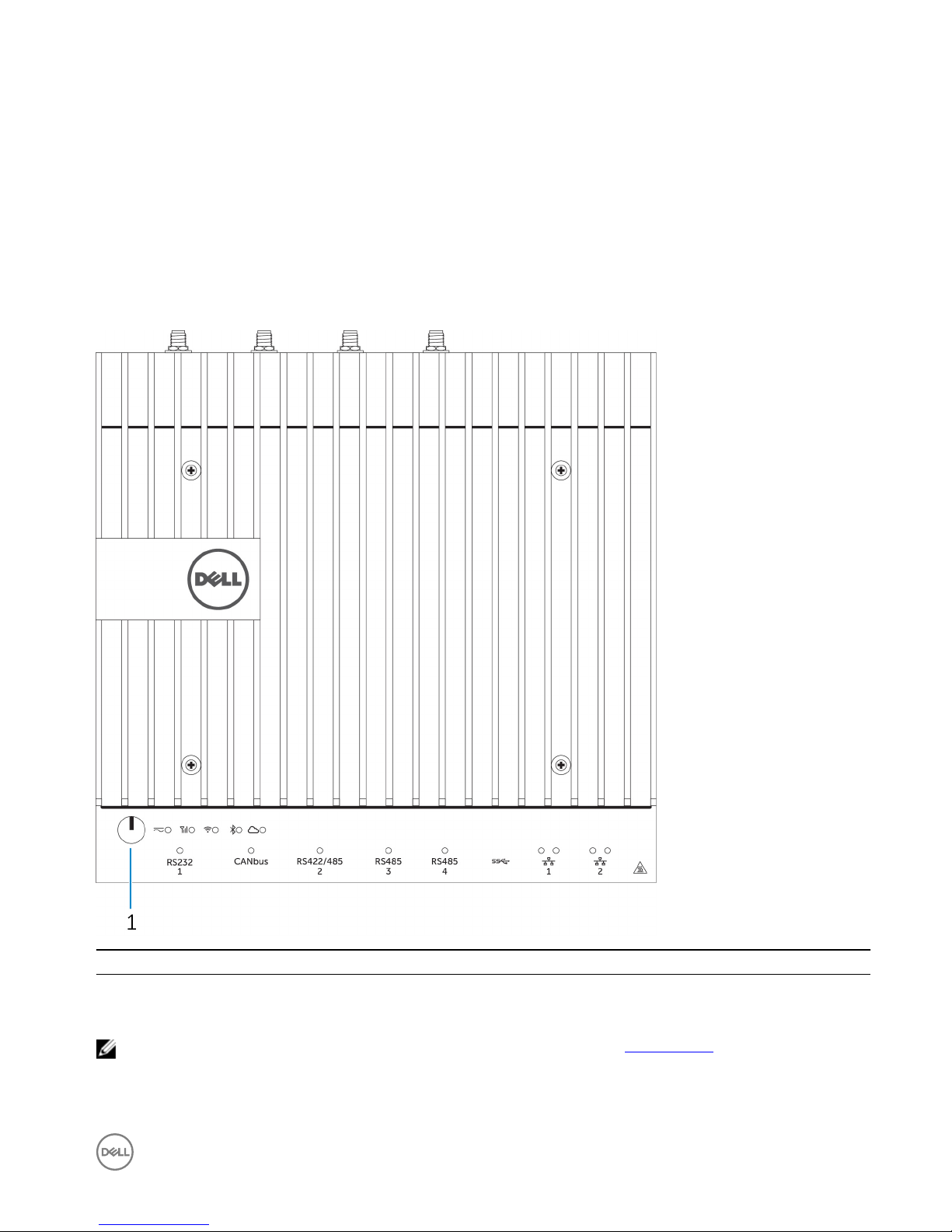
System—Front
Features
1 Power button Press and hold for 2 seconds to turn on the system if it is turned
o.
NOTE: For more details about the LED indicators on the front of the system, see LED indicators.
7
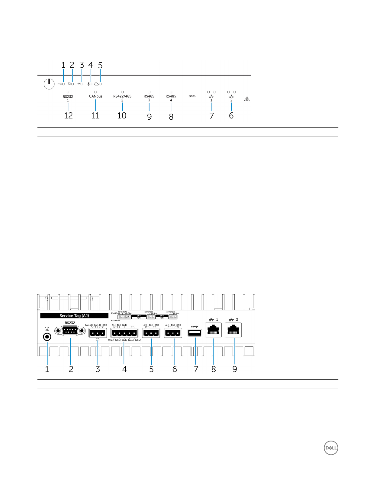
System—Front (LED indicators)
Features
1 Power status LED Indicates the power‑state of the system.
2 Mobile broadband status LED Indicates the mobile broadband status and network activity.
3 Wireless status LED Indicates the wireless connectivity status and network activity.
4 Bluetooth status LED Indicates the Bluetooth status and activity.
5 Cloud connection status LED Indicates the cloud connection status.
6 Network status LED Indicates the connectivity status and network activity.
7 Network status LED Indicates the connectivity status and network activity.
8 RS485 port status LED Provides the status of the RS485 port connections.
9 RS485 port status LED Provides the status of the RS485 port connections.
10 RS422/485 port status LED Provides the status of the RS422/485 port connections.
11 CANbus port status LED Provides the status of the CANbus port connection.
12 Serial port status LED Provides the status of the serial port connection.
System—Bottom
Features
1 Earth ground Connect the grounding cable to the system.
2 Serial port Connect to a serial port enabled device such as a printer.
3 CANbus port Connect to a CANbus port enabled device or dongle.
4 RS422/485 port Connect a RS422/485 device.
8
Features
5 RS485 port Connect a RS485 device.
6 RS485 port Connect a RS485 device.
7 USB 3.0 port Connect a USB 3.0 device.
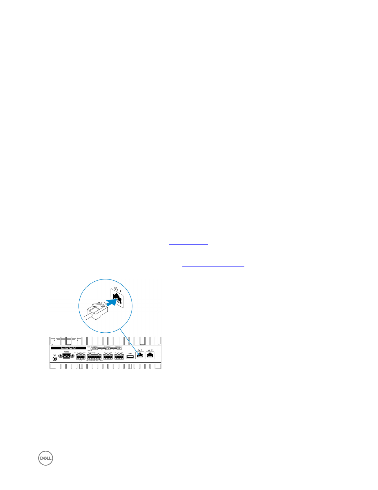
8 Network port Connect an Ethernet (RJ45) cable from a router or a broadband
modem for network or internet access.
9 Network port Connect an Ethernet (RJ45) cable from a router or a broadband
modem for network or internet access.
NOTE: For more details about the DIP switches on the bottom of the system, see DIP switches.
NOTE: For RS422 and RS485:
• Termination is 120-ohms between the members of the dierential pair when enabled.
• Bias is 4.7k pull-up (5V) / pull-down (Gnd) when enabled.
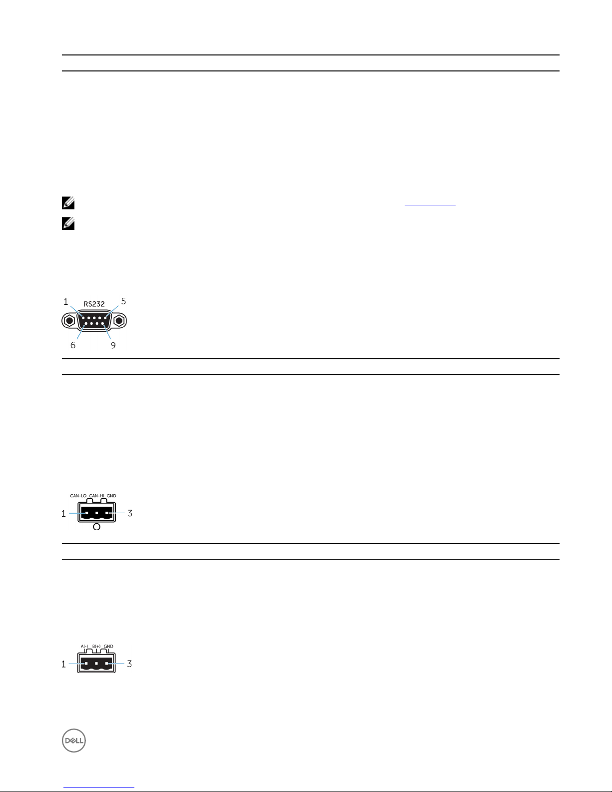
Serial port (RS232) connector mapping
Pin Signal Pin Signal
1 DCD 6 DSR
2 RXD 7 RTS
3 TXD 8 CTS
4 DTR 9 RI
5 GND
CANbus port connector mapping
PIN
Signal
1 CAN-LO
2 CAN-HI
3 GND
RS485 connector mapping
9
Pin Signal
1 A(-)
2 B(+)
3 GND
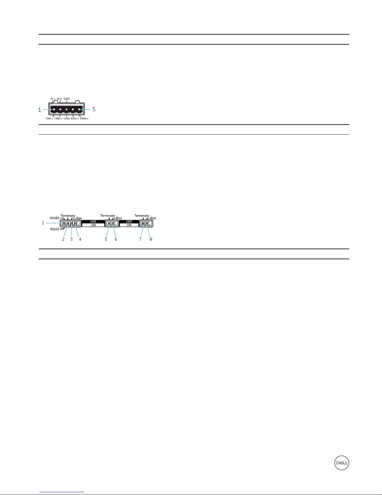
RS422/485 connector mapping
Pin Signal
1 TXA(-) / A(-)
2 TXB(+) / B(+)
3 GND
4 RXA(-)
5 RXB(+)
System—Bottom (DIP switches)
Feature
1 RS422/RS485 port toggle switch Toggle between RS422 or RS485 standard.
2 RS422/RS485 port resistor switch Enable/disable the dierential termination resistor.
3 RS422/RS485 port bias resistor switch Enable/disable the bias resistor for the RS422/RS485 port.
4 ePSA diagnostic switch When the position of the switch changes, the system starts in ePSA
(Enhanced Preboot System Assessment) mode on the next start.
5 RS485 port resistor switch Enable/disable the dierential termination resistor for RS485.
6 RS485 port bias resistor switch Enable/disable the bias resistor for the RS485 port.
7 RS485 port resistor switch Enable/disable the dierential termination resistor for RS485.
8 RS485 port bias resistor switch Enable/disable the bias resistor for the RS485 port.
10
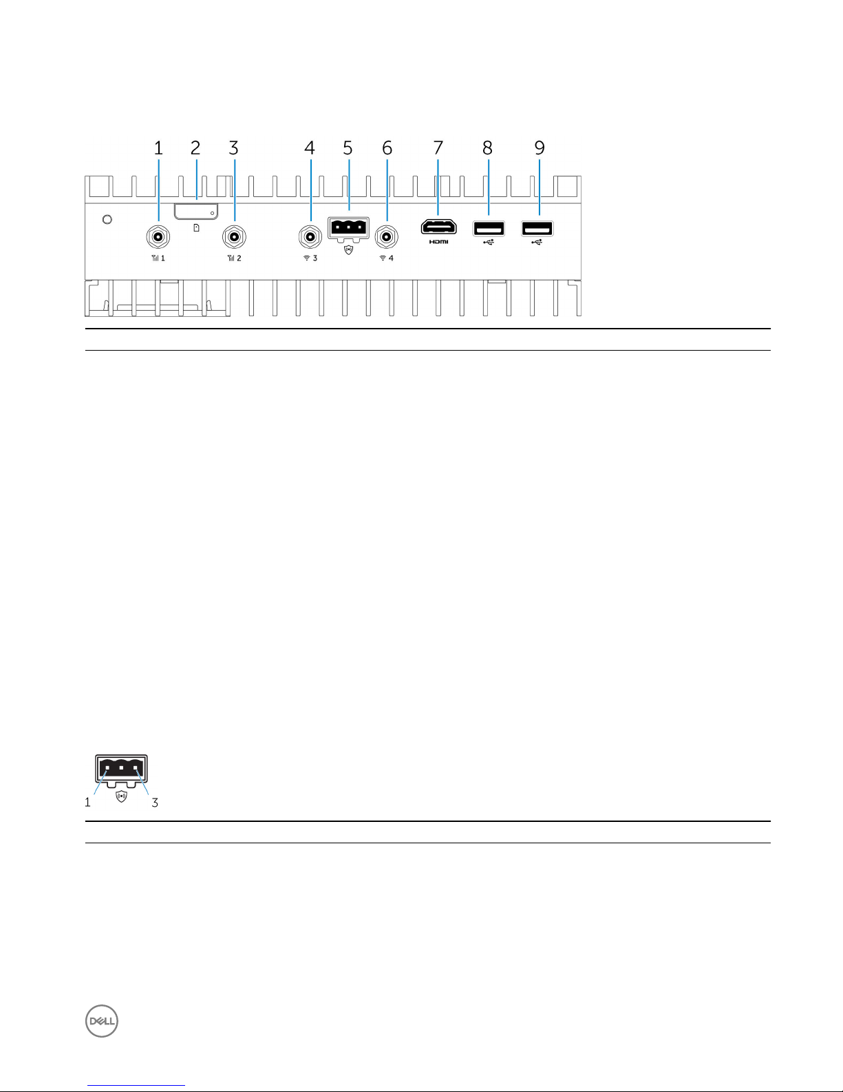
System—Top
Features
1 Mobile broadband antenna port (port one) Connect an antenna to increase the range and strength of the
mobile broadband signals.
2 Micro-SIM card slot Insert a micro-SIM card to connect to a mobile broadband
network.
3 Mobile broadband antenna port (port two) Connect an antenna to increase the range and strength of the
mobile broadband signals.
4 Wi-Fi antenna port (port three) Connect an antenna to increase the range and strength of Wi-Fi
signals.
5 Intrusion detection connector Connect an intrusion detection switch to detect any intrusion
into the system.
6 Wi-Fi antenna port (port four) Connect an antenna to increase the range and strength of Wi-Fi
signals.
7 HDMI port Connect a monitor or other HDMI device. Provides video and
audio output. Hot-plugging is supported on Windows 10 and
Ubuntu only.
8 USB 2.0 port Connect a USB 2.0 device.
9 USB 2.0 port Connect a USB 2.0 device.
Intrusion-detection connector mapping
Pin
Signal
1 GND
2 Intrusion detection
3 Cable detection
11

HDMI connector mapping
Pin Signal
1 TMDS Data2+
2 TMDS Data2 Shield
3 TMDS Data2−
4 TMDS Data1+
5 TMDS Data1 Shield
6 TMDS Data1−
7 TMDS Data0+
8 TMDS Data0 Shield
9 TMDS Data0−
10 TMDS Clock+
11 TMDS Clock Shield
12 TMDS Clock−
13 CEC
14 Reserved
15 SCL
16 SDA
17 Ground
18 +5 V (min. 0.055 A)
19 Hot Plug Detect
12
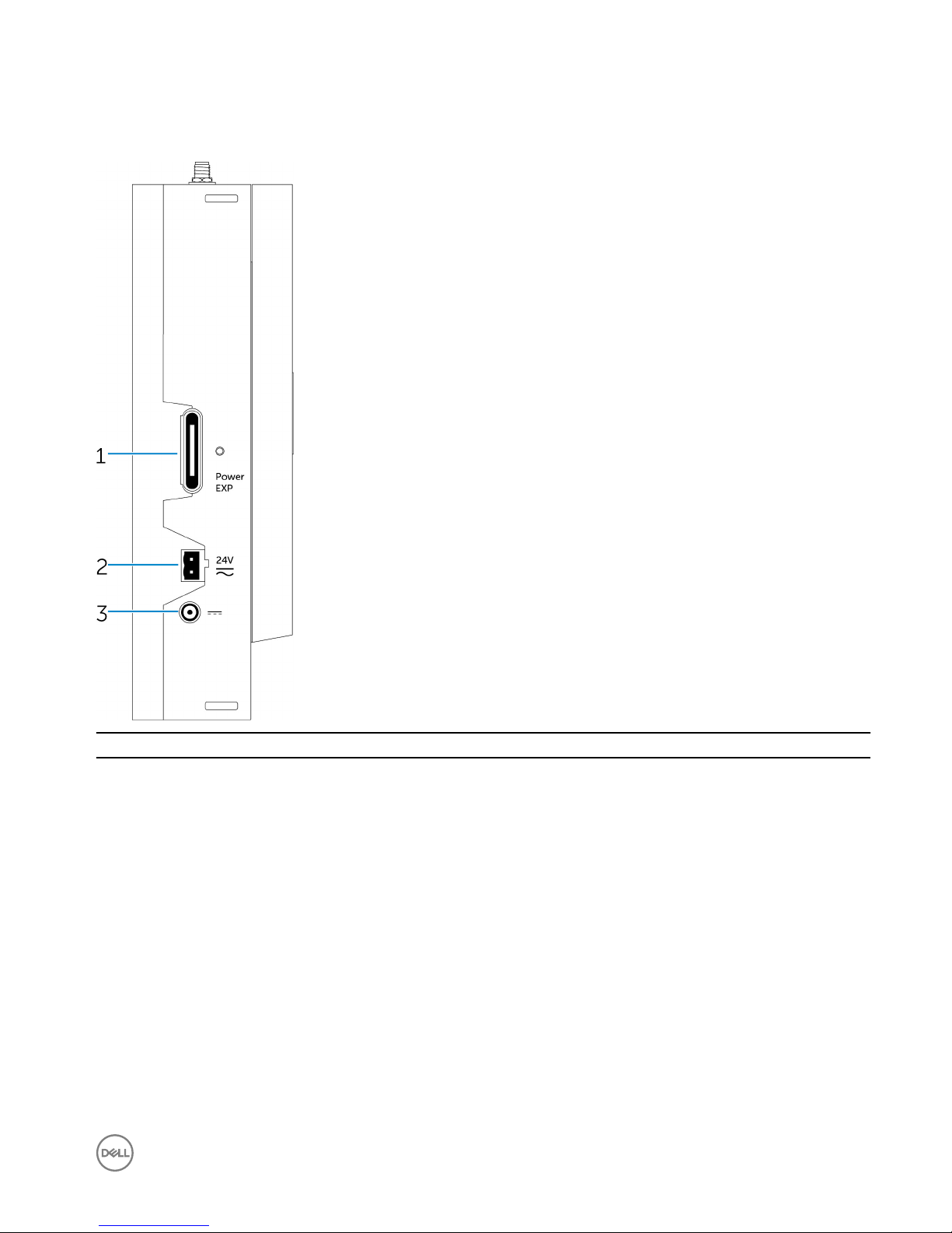
System—Left
Features
1 Power module expansion port Connect an external power module for increased power options.
2 24 V AC/DC power Phoenix connector Connect an 24 V AC/DC power connector to provide power to
your system.
3 19.5 V DC power adapter port Connect a 19.5 V DC power adapter connector to provide power
to your system.
13
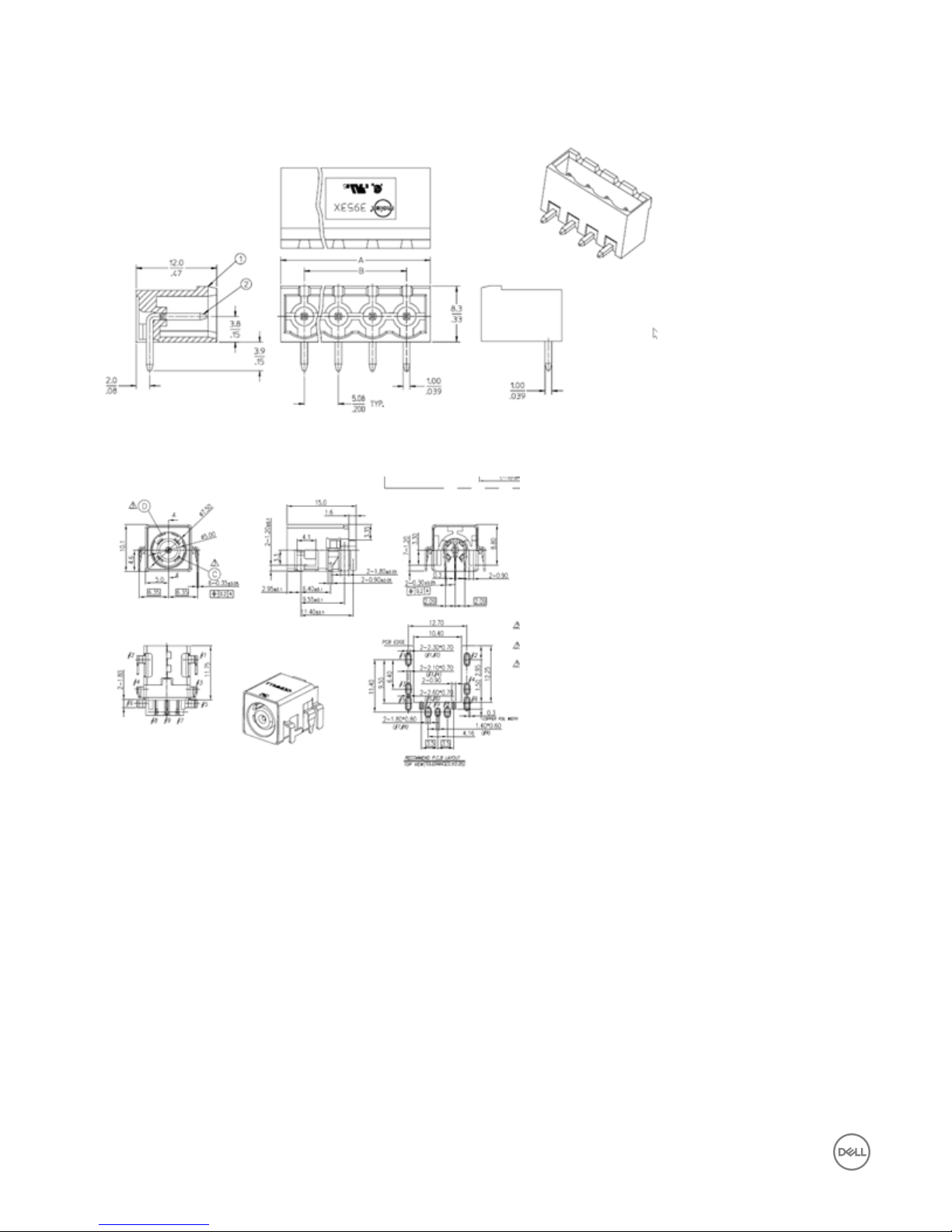
24 V AC/DC power port
19.5 V DC power adapter port
14
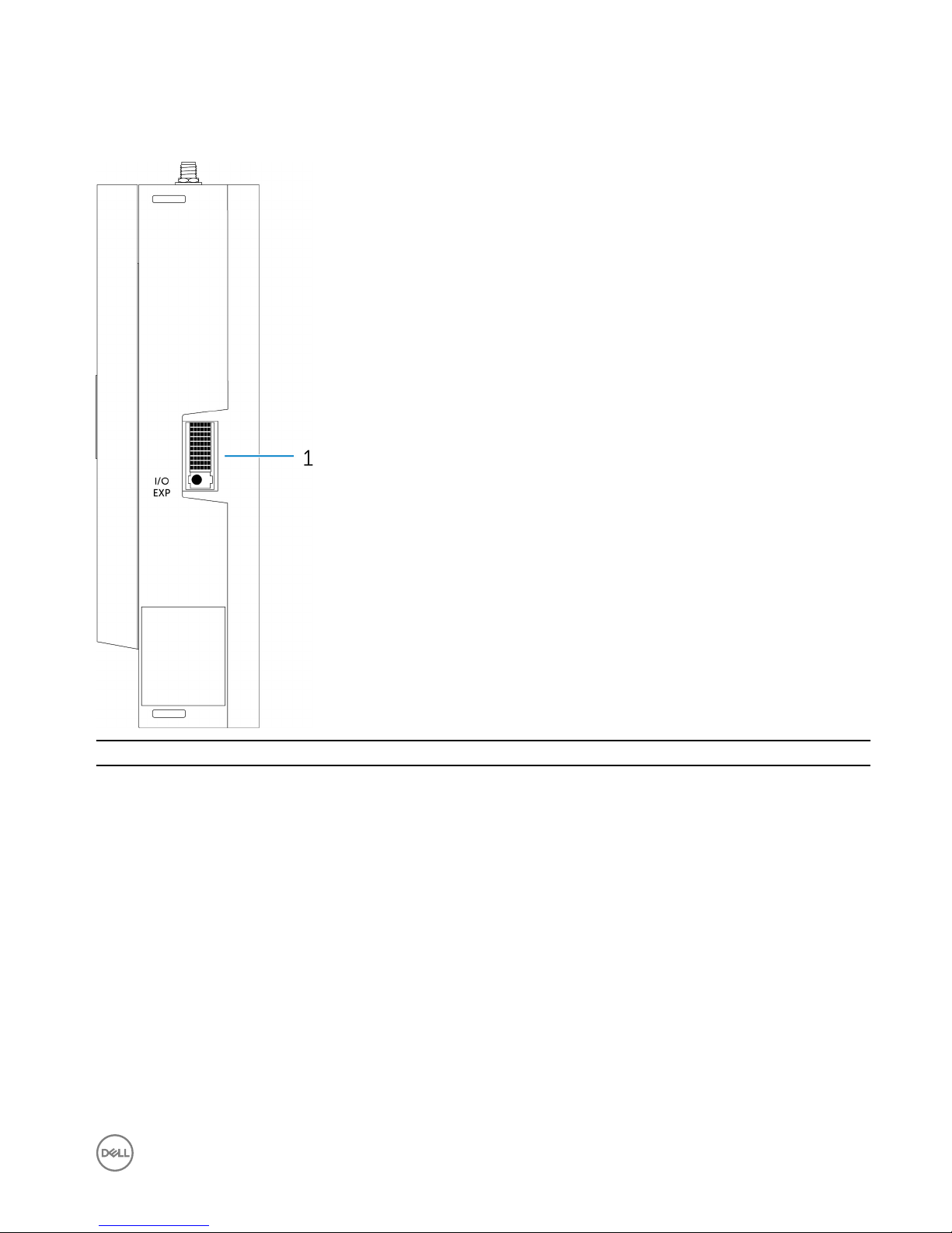
System—Right
Features
1 IO expansion port Connect an external expansion module for additional IO ports.
15

3
Setting up your Dell Edge Gateway
WARNING: Before you begin any of the procedures in this section, read the safety information that shipped with your
system. For additional best practices information, go to www.dell.com/regulatory_compliance.
WARNING: When installing the Gateway, the responsible party or integrator shall use the AC Adapter provided with the
Dell Edge Gateway, or connect to a 24Vac or 24Vdc power source already present as part of the clients installation.
WARNING: The Dell AC Adapter (full-wave rectied and have no built-in isolation transformer) is acceptable for use up to
ambient temperature of 40°C and is a limited power source, SELV/Limited Energy Circuit, Class 2 power source. If
ambient temperature of the installation exceeds 40 °C then use the 24Vac or 24Vdc power available as part of the
installation.
WARNING: Always make sure that the available power source matches the required input power of the Dell Edge
Gateway, check the input power markings next to power connector(s) before making connections. The 24 V power
source must be compliant with local Electrical Codes and Regulations.
WARNING: To ensure the protection provided by Dell Edge Gateway is not impaired, do not use or install the system in
any manner other than that which is specied in this manual.
WARNING: When installing the Gateway use acable appropriate for the load currents: 3-core cable rated 5 A at 90 °C
(194 °F) minimum, which conform to either IEC 60227 or IEC 60245. The system accepts cables from 0.8 to 2.5 mm (18
to 14 AWG).
WARNING: The symbol indicates hot surface or adjacent hot surface that can obtain temperature during normal
use that can cause a burn. Allow equipment to cool o or use protective gloves when handling to reduce risk of a burn.
WARNING: If a battery is included as part of System/Network, battery must be must be installed with appropriate
enclosure in accordance with local Fire and Electrical Codes and Laws.
WARNING: When installing the Power Module, use a cable appropriate for the load currents: 3-core cable rated 15 A at
90 °C (194 °F) minimum, which conform to either IEC60227 or IEC 60245. The Gateway accepts cables of 14 AWG
minimum.
WARNING: Before installing that all of three power inputs (Terminal Block/Power Jack/Battery Input) in power module
shall be protected by the 20 A fuses or circuit-breakers(over current protection device) in front of this system.
WARNING: The system is for installation in a suitable industrial enclosure (provides electrical, mechanical and re hazard
protection).
WARNING: The core module only can be wall mounted (without the need for an additional enclosure)
WARNING: Only Sealed Lead Acid (SLA) battery rated 50Ah (or less) shall be used
Professional installation instructions
Installation personnel
This product is designed for specic applications and needs to be installed by qualied personnel with RF and regulatory related
knowledge. The general user shall not attempt to install or change the setting.
Installation location
The product shall be installed at a location where the radiating antenna is kept 20 cm from nearby persons in its normal operation
condition in order to meet regulatory RF exposure requirements.
16

External antenna
Use only the antenna(s) which have been approved by the applicant. Non-approved antenna(s) may produce unwanted spurious or
excessive RF transmitting power which may lead to a violation of FCC/IC limits and is prohibited.
Installation procedure
Please refer to user’s manual for the detail.
WARNING: Please carefully select the installation position and make sure that the nal output power does not exceed
the limits set forth in relevant rules. The violation of these rules could possibly lead to serious federal penalties.
Instructions d'installation professionnelles
Le personnel d'installation
Ce produit est conçu pour des applications spéciques et doit être installé par un personnel qualié avec RF et connaissances
connexes réglementaire. L'utilisateur ne doit pas tenter générale d'installer ou de modier le réglage.
Lieu d'installation
Le produit doit être installé à un endroit où l'antenne de rayonnement est maintenue à 20 cm de personnes à proximité dans son état
de fonctionnement normal, an de répondre aux exigences réglementaires d'exposition aux radiofréquences.
Antenne externe
Utilisez uniquement l'antenne(s) qui ont été approuvés par le demandeur. Antenne (s) peuvent produire de l'énergie RF parasite
indésirable ou excessive transmission qui peut conduire à une violation des normes de la FCC / IC est interdite et non-approuvé.
Procédure d'installation
ATTENTION: S'il vous plaît choisir avec soin la position d'installation et assurez-vous que la puissance de sortie nal ne
dépasse pas les limites xées dans les règles pertinentes. La violation de ces règles pourrait conduire à des sanctions fédérales
graves.
Federal Communication Commission Interference Statement
This device complies with Part 15 of the FCC Rules. Operation is subject to the following two conditions: (1) This device may not
cause harmful interference, and (2) this device must accept any interference received, including interference that may cause
undesired operation.
This equipment has been tested and found to comply with the limits for a Class B digital device, pursuant to Part 15 of the FCC
Rules. These limits are designed to provide reasonable protection against harmful interference in a residential installation. This
equipment generates, uses and can radiate radio frequency energy and, if not installed and used in accordance with the instructions,
may cause harmful interference to radio communications. However, there is no guarantee that interference will not occur in a
particular installation. If this equipment does cause harmful interference to radio or television reception, which can be determined by
turning the equipment o and on, the user is encouraged to try to correct the interference by one of the following measures:
• Reorient or relocate the receiving antenna.
• Increase the separation between the equipment and receiver.
• Connect the equipment into an outlet on a circuit dierent from that to which the receiver is connected.
• Consult the dealer or an experienced radio/TV technician for help.
FCC Caution:
• Any changes or modications not expressly approved by the party responsible for compliance could void the user's authority to
operate this equipment.
17

• This transmitter must not be co-located or operating in conjunction with any other antenna or transmitter.
Radiation Exposure Statement:
This equipment complies with FCC radiation exposure limits set forth for an uncontrolled environment. This equipment should be
installed and operated with minimum distance 20cm between the radiator & your body.
NOTE: The country code selection is for non-US model only and is not available to all US model. Per FCC regulation, all
WiFi product marketed in US must xed to US operation channels only.
Industry Canada Statement
This device complies with Industry Canada license-exempt RSS standard(s). Operation is subject to the following two conditions:
1. this device may not cause interference, and
2. this device must accept any interference, including interference that may cause undesired operation of the device.
Le présent appareil est conforme aux CNR d'Industrie Canada applicables aux appareils radio exempts de licence. L'exploitation est
autorisée aux deux conditions suivantes:
1. l'appareil ne doit pas produire de brouillage, et
2. l'utilisateur de l'appareil doit accepter tout brouillage radioélectrique subi, même si le brouillage est susceptible d'en
compromettre le fonctionnement.
This Class B digital apparatus complies with Canadian ICES-003.
Cet appareil numérique de la classe B est conforme à la norme NMB-003 du Canada.
This device complies with RSS-210 of Industry Canada. Operation is subject to the condition that this device does not cause harmful
interference.
Cet appareil est conforme à la norme RSS-210 d'Industrie Canada. L'opération est soumise à la condition que cet appareil ne
provoque aucune interférence nuisible.
This device and its antenna(s) must not be co-located or operating in conjunction with any other antenna or transmitter, except
tested built-in radios.
Cet appareil et son antenne ne doivent pas être situés ou fonctionner en conjonction avec une autre antenne ou un autre émetteur,
exception faites des radios intégrées qui ont été testées.
The County Code Selection feature is disabled for products marketed in the US/Canada.
La fonction de sélection de l'indicatif du pays est désactivée pour les produits commercialisés aux États-Unis et au Canada.
Radiation Exposure Statement: This equipment complies with IC radiation exposure limits set forth for an uncontrolled environment.
This equipment should be installed and operated with minimum distance 20cm between the radiator & your body.
Déclaration d'exposition aux radiations: Cet équipement est conforme aux limites d'exposition aux rayonnements IC établies pour
un environnement non contrôlé. Cet équipement doit être installé et utilisé avec un minimum de 20 cm de distance entre la source de
rayonnement et votre corps.
Caution:
1. The device for operation in the band 5150-5250 MHz is only for indoor use to reduce the potential for harmful interference to
co-channel mobile satellite systems;
2. The maximum antenna gain permitted for devices in the bands 5250-5350 MHz and 5470-5725 MHz shall comply with the
eirp limit; and
18
3. The maximum antenna gain permitted for devices in the band 5725-5825 MHz shall comply with the eirp limits specied for
point-to-point and non point-to-point operation as appropriate.
4. The worst-case tilt angle(s) necessary to remain compliant with the eirp elevation mask requirement set forth in Section
6.2.2(3) shall be clearly indicated.
5. Users should also be advised that high-power radars are allocated as primary users (i.e. priority users) of the bands 5250-5350
MHz and 5650-5850 MHz and that these radars could cause interference and/or damage to LE-LAN devices.
Avertissement:
1. Les dispositifs fonctionnant dans la bande 5150-5250 MHz sont réservés uniquement pour une utilisation à l’intérieur an de
réduire les risques de brouillage préjudiciable aux systèmes de satellites mobiles utilisant les mêmes canaux;
2. Le gain maximal d’antenne permis pour les dispositifs utilisant les bandes 5250-5350 MHz et 5470-5725 MHz doit se
conformer à la limite de p.i.r.e.;
3. Le gain maximal d’antenne permis (pour les dispositifs utilisant la bande 5725-5825 MHz) doit se conformer à la limite de p.i.r.e.
spéciée pour l’exploitation point à point et non point à point, selon le cas.
4. Les pires angles d’inclinaison nécessaires pour rester conforme à l’exigence de la p.i.r.e. applicable au masque d’élévation, et
énoncée à la section 6.2.2 3), doivent être clairement indiqués.
5. De plus, les utilisateurs devraient aussi être avisés que les utilisateurs de radars de haute puissance sont désignés utilisateurs
principaux (c.-à-d., qu’ils ont la priorité) pour les bandes 5250-5350 MHz et 5650-5850 MHz et que ces radars pourraient
causer du brouillage et/ou des dommages aux dispositifs LAN-EL.
Setting up the Edge Gateway
Powering on the Edge Gateway
1. Install the Edge Gateway on the wall mount using a wall mounting kit.
or
Install the Edge Gateway on the rack infrastructure using DIN-rail mounting brackets.
2. Connect a network cable—optional.
3. Install the WLAN antenna to enable the wireless connections—optional.
19
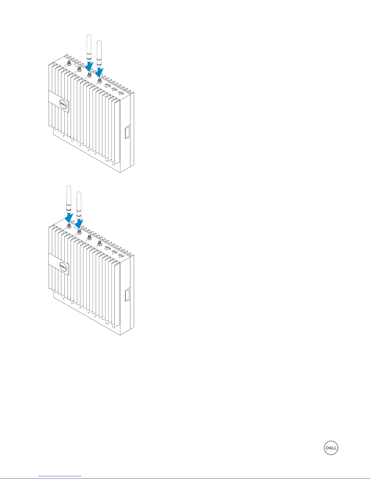
4. Install the WWAN antenna to enable the wireless connections—optional.
5. Connect a display to the Edge Gateway (if necessary).
20
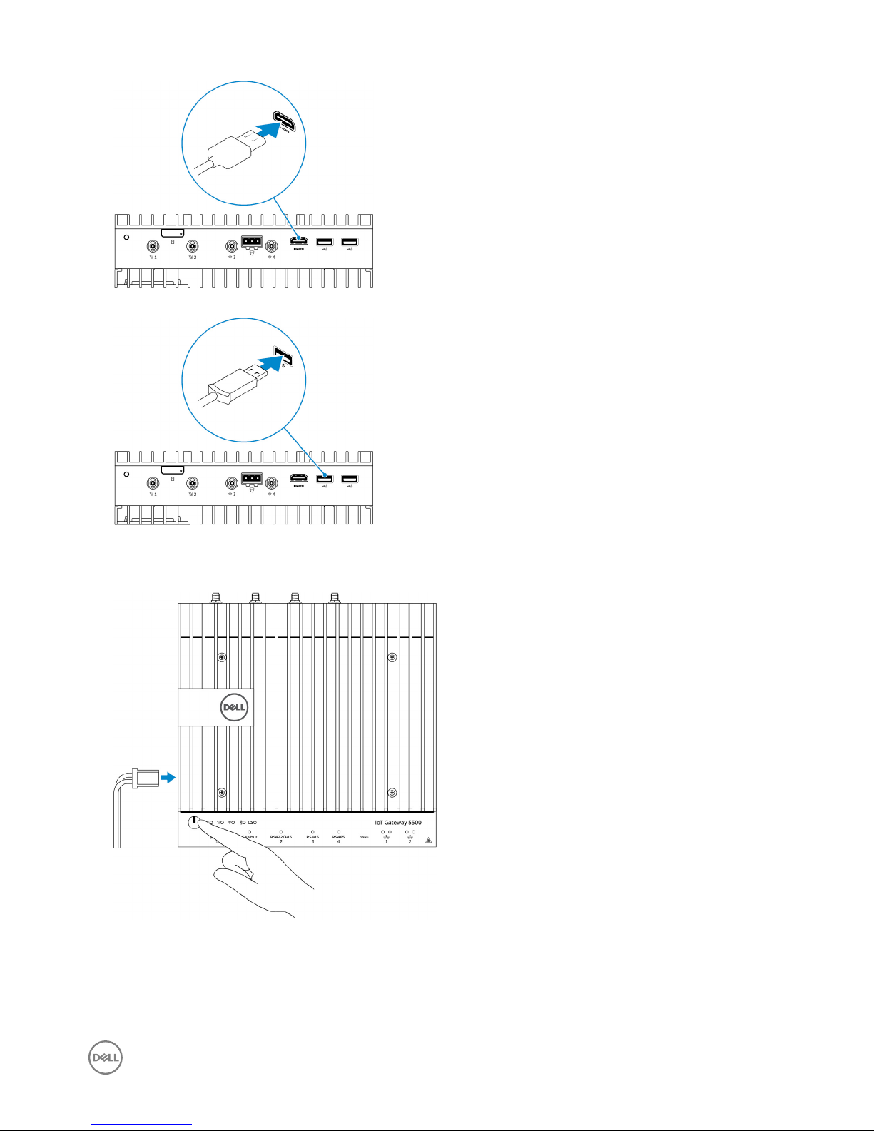
6. Connect a keyboard and mouse if accessing the Edge Gateway directly.
7. Connect a grounding cable to the Gateway (if necessary).
8. Connect a SELV/limited energy circuit power source to the Edge Gateway and press the power button to turn it on.
24 V AC/DC
or
19.5 V DC
21
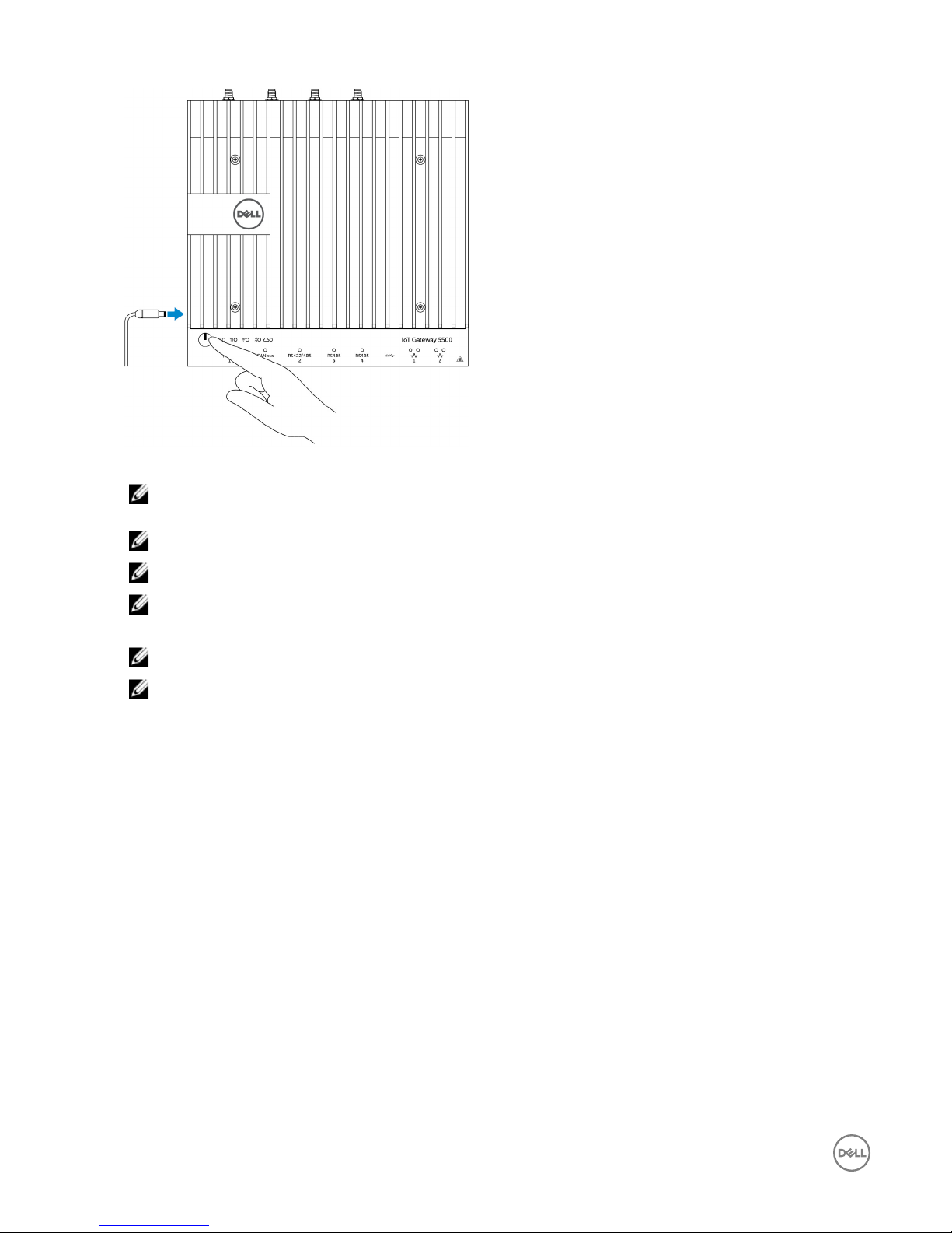
9. If setting up the Edge Gateway for the rst time, complete the operating system setup.
NOTE: The Edge Gateway is shipped with either Windows 10 Enterprise, Ubuntu Snappy, or Wind River Linux
operating systems.
NOTE: On Windows 10 OS, select
Do this later
when prompted to enter the product key.
NOTE: The default username and password for Ubuntu-Snappy-Core is
ubuntu
.
NOTE: The default username and password for Wind River is
root
.
10. Connect and congure devices using the RS422/RS485 ports.
NOTE: Turn on the corresponding dip switches to enable the RS422/R485 ports.
NOTE: After the Edge Gateway setup is complete, reinstall the dust covers on any unused ports.
Mounting the Edge Gateway on the wall
You can mount the Edge Gateway on a wall by using mounting brackets.
1. Secure the two mounting brackets to the back of the Edge Gateway by using four screws.
22
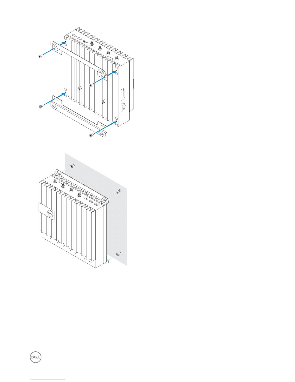
2. Drill four holes in the wall that correspond to the holes in the mounting bracket, then place the Edge Gateway against the wall
and align the holes in the mounting brackets with the holes in the wall.
3. Tighten the screws to secure the Edge Gateway to the wall.
23
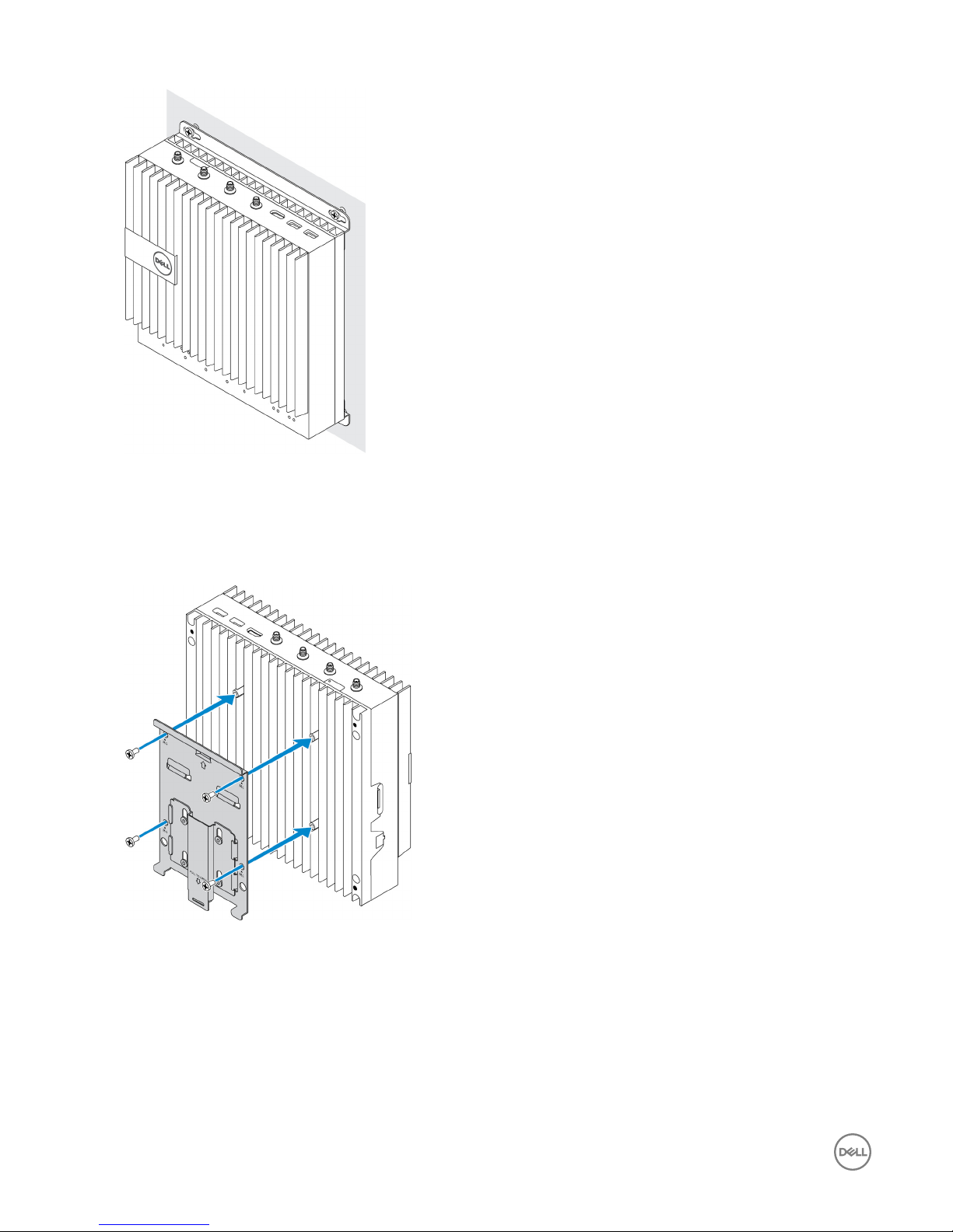
Mounting the Edge Gateway on a DIN rail
The Edge Gateway can be mounted on a DIN rail. The DIN rail bracket mounts to the back of the Edge Gateway.
1. Align the screw holes on the DIN rail mount to the back of the Edge Gateway, place the screws on the DIN rail mount and
secure it to the Edge Gateway.
2. Pull down on the tab to release the latch on the DIN rail mount.
24
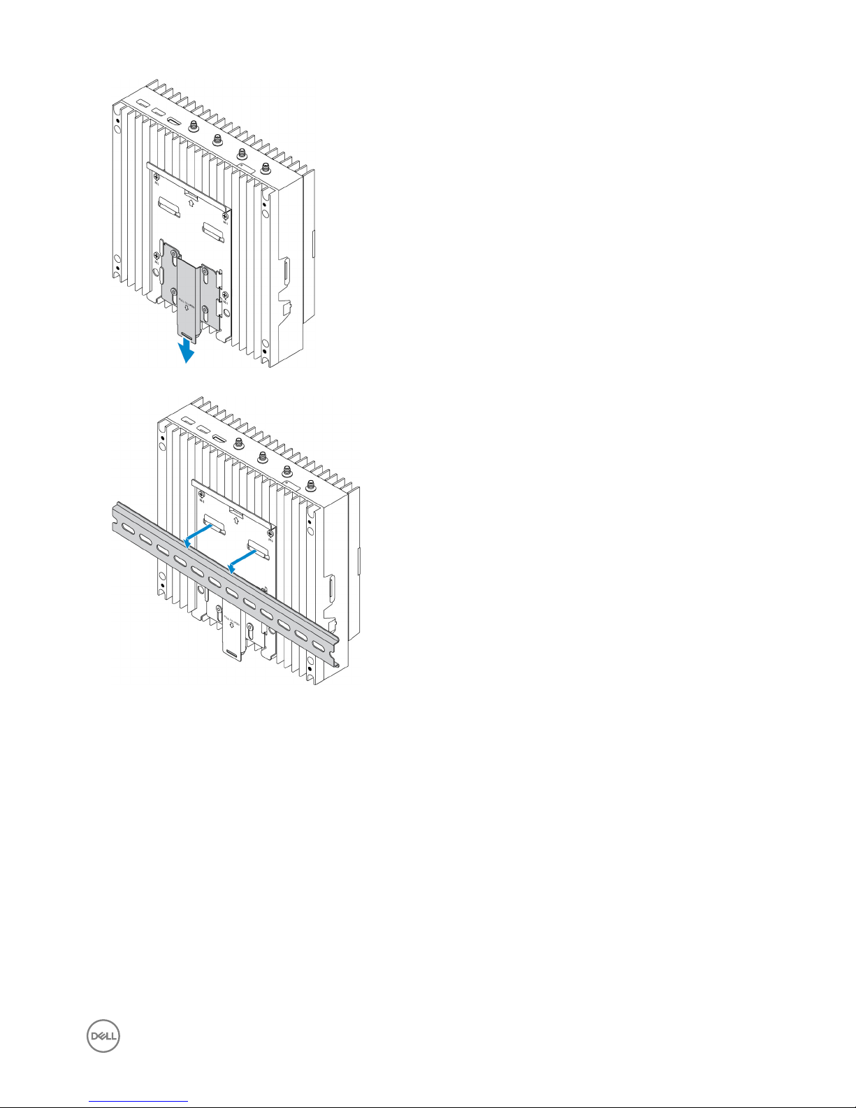
3. Mount the Edge Gateway on a DIN rail.
4. Secure the Edge Gateway to the DIN rail by pressing the latch.
25
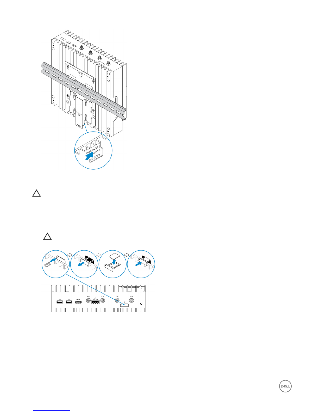
Inserting a micro-SIM card and activating your mobile broadband
CAUTION: Dell recommends that you insert the micro-SIM card before powering on the Edge Gateway.
1. Shut down your Edge Gateway.
2. Locate the micro-SIM card slot.
3. Use a paper clip or SIM eject tool to eject the micro-SIM card tray.
4. Place the micro-SIM card on the tray.
CAUTION: Ensure that the micro-SIM card is aligned as shown in the image.
5. Close the micro-SIM card tray.
6. Turn on your Edge Gateway.
7. Connect to a mobile network.
Windows operating system
If the Edge Gateway is shipped with HSPA+ (DW5580) WWAN card:
a. Launch the Telit Mobile Broadband Manager.
26

b. Click the play button to connect to your HSPA+ network.
NOTE: Click the information button to view the International Mobile Equipment Identity (IMEI) and
Integrated Circuit Card Identier (ICCID) information.
Click the stop to disconnect from your HSPA+ network.
If the Edge Gateway is shipped with LTE Verizon (DW5812) WWAN or LTE AT&T (DW5813) card:
a. Select the network icon from the taskbar and then click Cellular.
b. Select your Mobile Broadband Carrier → Advanced Options.
c. Make a note of the International Mobile Equipment Identity (IMEI) and the Integrated Circuit Card Identier (ICCID).
Ubuntu operating system
a. Open the Terminal window.
b. Go to super user mode by entering:$sudo su -
c. Congure the Mobile Broadband connection prole:
#nmcli con add type gsm ifname ttyACM3 con-name <connection name> apn <apn> user
<user name> password <password>
d. Connect to the mobile network: #nmcli con up connection name
NOTE: To view the IMEI and ICCID number use the mmcli -m 0 --command=+CIMI command.
To disconnect from the mobile network: #nmcli con downconnection name.
Wind River operating system
If the Edge Gateway is shipped with HSPA+ (DW5580) WWAN card:
a. Open the Terminal window.
b. Congure the Mobile Broadband APN prole:
#uci set network.wwan.apn="<apn>"
#uci commit network
c. Connect to the mobile network: #ifup wwan
NOTE: To view the IMEI and ICCID number use the AT+IMEISV command.
To disconnect from the mobile network: #ifdown wwan.
If the Edge Gateway is shipped with LTE Verizon (DW5812) WWAN card:
Open the Terminal window.
a. In the terminal type AT+IMEISV to open the Minicom terminal.
The Minicom terminal opens with the following text:
Welcome to minicom 2.7
OPTIONS: I18n
Compiled on Dec 17 2015, 16:20:45.
Port /dev/ttyACM0, 21:33:05
Press CTRL-A Z for help on special keys
b. Type the AT+cgdcont command with PDP Context Identier, “Packet Data Protocol type”, and “Access Point Name”
parameters and press Enter.
27

Example: at+cgdcont=3,"IPV4V6","vzwinternet".
NOTE: If the command runs successfully, the message OK appears.
c. Congure the Network Control Mode with the at#ncm command.
Example: at#ncm=1,3.
d. Activate the Packet Data Protocol with the at+cgact command.
Example: at+cgact=1,3.
e. To view the PDP Context Read Dynamic Parameters, that is, bearer_id, apn, ip_addr, subnet_mask, gw_addr,
DNS_prim_addr, DNS_sec_addr, P-CSCF_prim_addr, and P-CSCF_sec_addr parameters, run the at+cgcontrdp
command.
Example: at+cgcontrdp=3
+CGCONTRDP: 3,7,"vzwinternet.mnc480.mcc311.gprs","100.106.47.7.255.0.0.0","100.1
06.47.8","198.224.157.135","0.0.0.0","0.0.0.0","0.0.00"
f. Exit the Minicom module.
g. In the Linux terminal congure the connection with the following commands
root@WR-IntelligentDevice:~# ifconfig wwan0 ip_addr netmask subnet_mask up
root@WR-IntelligentDevice:~# route add default gw gw_addr wwan0
root@WR-IntelligentDevice:~# echo nameserver DNS_prim_addr >>/etc/resolv.conf
Example:
root@WR-IntelligentDevice:~# ifconfig wwan0 100.106.47.7 netmask 255.0.0.0 up
root@WR-IntelligentDevice:~# route add default gw 100.106.47.8 wwan0
root@WR-IntelligentDevice:~# echo nameserver 198.224.157.135 >>/etc/resolv.conf
h. Log in to the Minicom module using the minicom -D /dev/ttyACM0 command.
i. Connect to the mobile network using the at+cgdata command.
Example:at+cgdata="M-RAW_IP",3
NOTE: To view the IMEI and ICCID number use the AT+IMEISV command.
To disconnect from the mobile network
a. Open the Minicom terminal.
b. Enter the at+cgdata="M-RAW_IP",3 command.
c. Close the Minicom terminal.
d. Enter the root@WR-IntelligentDevice:~# ifconfig wwan0 down command.
If the Edge Gateway is shipped with LTE AT&T (DW5813) WWAN card:
a. Open the Terminal window.
b. In the terminal type minicom -D /dev/ttyACM0 to open the Minicom terminal.
The Minicom terminal opens with the following text:
Welcome to minicom 2.7
OPTIONS: I18n
Compiled on Dec 17 2015, 16:20:45.
Port /dev/ttyACM0, 21:33:05
Press CTRL-A Z for help on special keys
c. Type the AT+cgdcont command with PDP Context Identier, “Packet Data Protocol type”, and “Access Point Name”
parameters and press Enter.
28

Example: at+cgdcont=3,"IPV4V6","broadband".
NOTE: If the command runs successfully, the message OK appears.
d. Congure the Network Control Mode with the at#ncm command.
Example: at#ncm=1,3.
e. Activate the Packet Data Protocol with the at+cgact command.
Example: at+cgact=1,3.
f. To view the PDP Context Read Dynamic Parameters, that is, bearer_id, apn, ip_addr, subnet_mask, gw_addr,
DNS_prim_addr, DNS_sec_addr, P-CSCF_prim_addr, and P-CSCF_sec_addr parameters, run the at+cgcontrdp
command.
Example: at+cgcontrdp=3
+CGCONTRDP: 3,7,"broadband.mnc480.mcc311.gprs","100.106.47.7.255.0.0.0","100.1
06.47.8","198.224.157.135","0.0.0.0","0.0.0.0","0.0.00"
g. Exit the Minicom module.
h. In the Linux terminal congure the connection with the following commands
root@WR-IntelligentDevice:~# ifconfig wwan0 ip_addr netmask subnet_mask up
root@WR-IntelligentDevice:~# route add default gw gw_addr wwan0
root@WR-IntelligentDevice:~# echo nameserver DNS_prim_addr >>/etc/resolv.conf
Example:
root@WR-IntelligentDevice:~# ifconfig wwan0 100.106.47.7 netmask 255.0.0.0 up
root@WR-IntelligentDevice:~# route add default gw 100.106.47.8 wwan0
root@WR-IntelligentDevice:~# echo nameserver 198.224.157.135 >>/etc/resolv.conf
i. Log in to the Minicom module using the minicom -D /dev/ttyACM0 command.
j. Connect to the mobile network using the at+cgdata command.
Example:at+cgdata="M-RAW_IP",3
To disconnect from the mobile network
a. Open the Minicom terminal.
b. Enter the at+cgdata="M-RAW_IP",3 command.
c. Close the Minicom terminal.
d. Enter the root@WR-IntelligentDevice:~# ifconfig wwan0 down command.
Replacing the micro-SIM card
CAUTION: Removing the micro-SIM card while it is in use may cause data loss or result in application errors.
1. Using a paper clip or SIM eject tool, eject the micro-SIM card tray.
2. Remove the micro-SIM card from the micro-SIM card tray.
3. Replace the micro-SIM card tray into the Gateway.
29

4
Setting up your operating system
CAUTION: To prevent operating system corruption from sudden power loss, use the operating system to gracefully shut
down the Edge Gateway.
Windows 10 LTSB 2015
Overview
The Edge Gateway is shipped with Windows 10 IoT Enterprise LTSB 2015. For more information on Windows 10 operating system,
see https://support.microsoft.com/en-us.
Boot up and login
1. Connect a keyboard, mouse, and monitor to the Edge Gateway.
2. Power on the Edge Gateway.
The system boots into Windows 10 IoT Enterprise LTSB 2015.
3. Select your regional settings.
NOTE: If prompted for a product key, and one is already entered, select Do this later.
4. Read and Agree the End User License Agreement.
5. Connect to an available wireless or wired network.
6. Create a user account.
Restoring Windows 10 IoT Enterprise LTSB 2015
You can restore Windows 10 IoT Enterprise LTSB 2015 on the Edge Gateway using the recovery Operating System image on the
boot partition which resets the run-time image back to the factory image.
1. Connect a keyboard, mouse, and monitor to the Edge Gateway.
2. Power on the Edge Gateway and boot to the operating system’s desktop.
3. Click the start icon, hold the Shift key and click Restart.
4. Select Troubleshoot.
5. Select Reset this PC.
6. Select Remove everything.
7. Select Fully clean the drive.
8. Select Reset.
Windows 10 IOT Enterprise LTSB 2015 basic functions
BIOS Update
BIOS updates for the Edge Gateway may be downloaded from https://www.dell.com/support. The download will include an
executable that may be ran from the local machine.
30
 Loading...