

Dell E28S Series, PowerEdge R430 Owner's Manual

Dell PowerEdge R430
Version 1
Owner's Manual
E28S Series
A03

Copyright © 2017 - 10- Dell All rights reserved.
Dell believes the information in this publication is accurate as of its publication date. The information is subject to change without notice.
THE INFORMATION IN THIS PUBLICATION IS PROVIDED “AS-IS.” DELL MAKES NO REPRESENTATIONS OR WARRANTIES OF ANY KIND
WITH RESPECT TO THE INFORMATION IN THIS PUBLICATION, AND SPECIFICALLY DISCLAIMS IMPLIED WARRANTIES OF
MERCHANTABILITY OR FITNESS FOR A PARTICULAR PURPOSE. USE, COPYING, AND DISTRIBUTION OF ANY DELL SOFTWARE DESCRIBED
IN THIS PUBLICATION REQUIRES AN APPLICABLE SOFTWARE LICENSE.
Dell Technologies, Dell, EMC, Dell EMC and other trademarks are trademarks of Dell Inc. or its subsidiaries. Other trademarks may be the property
of their respective owners. Published in the USA.
Dell EMC
Hopkinton, Massachusetts 01748-9103
1-508-435-1000 In North America 1-866-464-7381
www.DellEMC.com
2 Dell PowerEdge R430 Owner's Manual

CONTENTS
Notes, cautions, and warnings 0
0
Chapter 1
Chapter 2
Dell PowerEdge R430 system overview 9
Supported configurations for the PowerEdge R430 system..............................10
Front panel features.......................................................................................... 10
Front panel features of a 4 x 3.5-inch hard drive system.......................11
Front panel features of the 4 x 3.5-inch cabled hard drive system........13
Front panel features of the 8 x 2.5 inch hard drives or SSDs system....15
Front panel features of the 10 x 2.5-inch hard drives or SSDs system....
17
LCD panel............................................................................................. 18
Back panel features........................................................................................... 21
Redundant PSU back panel features ....................................................21
Cabled PSU back panel features ......................................................... 23
Diagnostic Indicators........................................................................................ 26
Diagnostic indicators on the front panel...............................................26
Hard drive indicator codes....................................................................27
uSATA SSD indicator codes................................................................. 28
NIC indicator codes..............................................................................29
Internal dual SD module indicator codes...............................................30
iDRAC Direct LED indicator codes........................................................ 31
Indicator codes for redundant power supply unit................................. 32
Non-redundant power supply unit indicator codes............................... 34
Locating Service Tag of your system................................................................ 35
Documentation resources 37
Chapter 3
Technical specifications 41
Chassis dimensions........................................................................................... 42
Chassis weight..................................................................................................42
Processor specifications................................................................................... 43
PSU specifications............................................................................................43
System battery specifications...........................................................................43
Expansion bus specifications.............................................................................43
Memory specifications......................................................................................44
Drive specifications...........................................................................................44
Hard drives...........................................................................................44
Optical drive.........................................................................................45
Ports and connectors specifications................................................................. 45
USB ports............................................................................................ 45
NIC ports............................................................................................. 45
Serial connector...................................................................................46
VGA ports............................................................................................ 46
Internal Dual SD Module.......................................................................46
Video specifications.......................................................................................... 46
Dell PowerEdge R430 Owner's Manual 3

Contents
Environmental specifications............................................................................ 46
Particulate and gaseous contamination specifications .........................48
Expanded operating temperature.........................................................49
Expanded operating temperature restrictions...................................... 50
Chapter 4
Chapter 5
Chapter 6
Initial system setup and configuration 51
Setting up your system.....................................................................................52
iDRAC configuration......................................................................................... 52
Options to set up iDRAC IP address.....................................................52
Options to install the operating system.............................................................53
Methods to download firmware and drivers......................................... 53
Pre-operating system management applications 55
Options to manage the pre-operating system applications............................... 56
System Setup................................................................................................... 56
Viewing System Setup......................................................................... 56
System Setup details........................................................................... 56
System BIOS........................................................................................57
iDRAC Settings utility.......................................................................... 80
Device Settings.................................................................................... 81
Dell Lifecycle Controller.....................................................................................81
Embedded system management........................................................... 81
Boot Manager....................................................................................................81
Viewing Boot Manager..........................................................................81
Boot Manager main menu.................................................................... 82
PXE boot.......................................................................................................... 82
Installing and removing system components 83
Safety instructions............................................................................................84
Before working inside your system....................................................................84
After working inside your system...................................................................... 84
Recommended tools......................................................................................... 85
Front bezel (optional)....................................................................................... 85
Removing the optional front bezel....................................................... 85
Installing the optional front bezel......................................................... 86
System cover....................................................................................................87
Removing the system cover................................................................. 87
Installing the system cover...................................................................88
Inside the system..............................................................................................89
Cooling shroud..................................................................................................92
Removing the cooling shroud............................................................... 92
Installing the cooling shroud.................................................................93
System memory................................................................................................94
General memory module installation guidelines.................................... 96
Mode-specific guidelines......................................................................96
Sample memory configurations............................................................ 97
Removing memory modules................................................................102
Installing memory modules..................................................................103
Hard drives......................................................................................................105
Removing a 2.5-inch hard drive blank.................................................105
Installing a 2.5-inch hard drive blank...................................................106
Removing a 3.5-inch hard drive blank................................................. 107
Installing a 3.5-inch hard drive blank...................................................107
Removing a 3.5-inch cabled hard drive carrier....................................108
4 Dell PowerEdge R430 Owner's Manual

Contents
Installing a 3.5-inch cabled hard drive carrier..................................... 109
Removing a hot swappable hard drive carrier...................................... 110
Installing a hot swappable hard drive carrier........................................ 111
Removing a 3.5-inch hot swappable hard drive adapter from a 3.5-inch
hot swappable hard drive carrier......................................................... 113
Installing a 3.5-inch hard drive adapter into a hot swap hard drive carrier
............................................................................................................114
Removing a 2.5-inch hard drive from a 3.5-inch hard drive adapter.... 114
Installing a 2.5-inch hard drive into a 3.5-inch hard drive adapter....... 115
Removing a hard drive from a hard drive carrier..................................116
Installing a hard drive into a hard drive carrier..................................... 117
Optical drive (optional).................................................................................... 118
Removing the optional ultra slim optical drive..................................... 118
Installing the optional ultra slim optical drive....................................... 119
Removing the standard optical drive...................................................120
Installing the standard optical drive..................................................... 121
Cooling fans.....................................................................................................123
Removing a cooling fan.......................................................................123
Installing a cooling fan........................................................................ 124
Internal USB memory key (optional)................................................................125
Replacing the optional internal USB memory key................................125
Expansion cards and expansion card riser........................................................127
Expansion card installation guidelines................................................. 127
Removing the expansion card riser..................................................... 128
Installing the expansion card riser.......................................................129
Removing an expansion card.............................................................. 130
Installing an expansion card.................................................................131
iDRAC port card (optional).............................................................................. 132
Removing the optional iDRAC port card..............................................133
Installing the optional iDRAC port card............................................... 134
SD vFlash card (optional)................................................................................ 136
Removing the optional SD vFlash card................................................136
Installing an optional SD vFlash card...................................................136
Internal dual SD module (optional)...................................................................137
Removing an internal SD card............................................................. 137
Installing an internal SD card.............................................................. 138
Removing the optional internal dual SD module.................................. 139
Installing the optional internal dual SD module ...................................140
Integrated storage controller card....................................................................141
Removing the integrated storage controller card................................142
Installing the integrated storage controller card................................. 143
Processors and heat sinks............................................................................... 144
Removing a heat sink..........................................................................145
Removing a processor........................................................................ 146
Installing a processor.......................................................................... 148
Installing a heat sink............................................................................ 151
Power supply units.......................................................................................... 153
Hot spare feature............................................................................... 153
Removing a redundant power supply unit........................................... 154
Installing a redundant power supply unit.............................................155
Removing a cabled power supply unit................................................. 156
Installing a cabled power supply unit...................................................157
Removing the power supply unit blank................................................159
Installing the power supply unit blank................................................. 159
System battery................................................................................................160
Replacing the system battery............................................................. 160
Dell PowerEdge R430 Owner's Manual 5

Contents
Hard-drive backplane...................................................................................... 162
Removing the hard drive backplane.................................................... 162
Installing the hard drive backplane......................................................169
Control panel....................................................................................................171
Removing the control panel.................................................................171
Installing the control panel.................................................................. 173
Removing the control panel module.................................................... 175
Installing the control panel module......................................................178
Power interposer board....................................................................................181
Removing the power interposer board.................................................181
Installing the power interposer board..................................................182
System board.................................................................................................. 183
Removing the system board............................................................... 183
Installing the system board................................................................. 185
Trusted Platform Module.................................................................................188
Installing the Trusted Platform Module...............................................188
Initializing the TPM for BitLocker users..............................................189
Initializing the TPM for TXT users...................................................... 189
Chapter 7
Chapter 8
Chapter 9
Using system diagnostics 191
Dell Embedded System Diagnostics.................................................................192
When to use the Embedded System Diagnostics................................ 192
Running the Embedded System Diagnostics from Boot Manager....... 192
Running the Embedded System Diagnostics from the Dell Lifecycle
Controller........................................................................................... 192
System diagnostic controls.................................................................192
Jumpers and connectors 195
System board jumper settings......................................................................... 196
System board connectors................................................................................197
Disabling a forgotten password....................................................................... 199
Troubleshooting your system 201
Troubleshooting system startup failure...........................................................202
Troubleshooting external connections............................................................ 202
Troubleshooting the video subsystem.............................................................202
Troubleshooting a USB device........................................................................ 202
Troubleshooting a serial I/O device.................................................................203
Troubleshooting a NIC.................................................................................... 203
Troubleshooting a wet system........................................................................ 204
Troubleshooting a damaged system................................................................205
Troubleshooting the system battery............................................................... 206
Troubleshooting power supply units................................................................206
Troubleshooting power source problems............................................206
Power supply unit problems............................................................... 207
Troubleshooting cooling problems...................................................................207
Troubleshooting cooling fans.......................................................................... 208
Troubleshooting system memory.................................................................... 208
Troubleshooting an internal USB key.............................................................. 209
Troubleshooting an SD card............................................................................ 210
Troubleshooting an optical drive.......................................................................211
Troubleshooting a hard drive............................................................................211
Troubleshooting a storage controller............................................................... 212
Troubleshooting expansion cards.....................................................................213
6 Dell PowerEdge R430 Owner's Manual

Contents
Troubleshooting processors.............................................................................214
System messages............................................................................................ 214
Warning messages..............................................................................214
Diagnostic messages...........................................................................214
Alert messages................................................................................... 214
Chapter 10
Getting help 217
Contacting Dell................................................................................................218
Documentation feedback.................................................................................218
Accessing system information by using QRL................................................... 218
Quick Resource Locator for the PowerEdge R430 system................. 219
Dell PowerEdge R430 Owner's Manual 7

Contents
8 Dell PowerEdge R430 Owner's Manual

CHAPTER 1
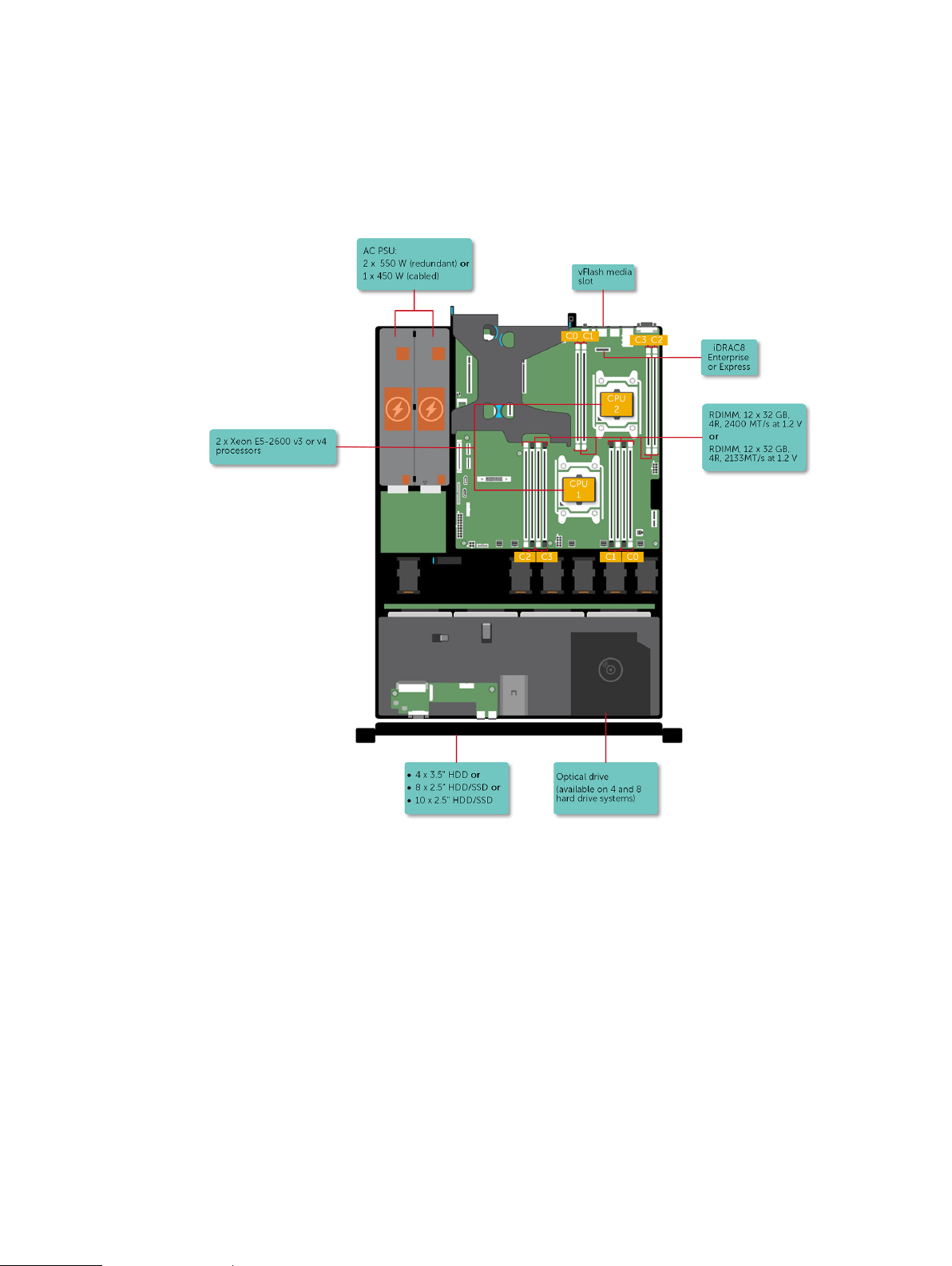
Dell PowerEdge R430 system overview
The Dell PowerEdge R430 systems are 2U rack servers that support up to two Intel Xeon E5-2600
v3 or Xeon E5-2600 v4 processors, up to 12 DIMMs, and ten hard drives or solid state drives
(SSDs).
l
Supported configurations for the PowerEdge R430 system.................................................. 10
l
Front panel features...............................................................................................................10
l
Back panel features................................................................................................................21
l
Diagnostic Indicators.............................................................................................................26
l
Locating Service Tag of your system.................................................................................... 35
Dell PowerEdge R430 Owner's Manual 9
Dell PowerEdge R430 system overview
Supported configurations for the PowerEdge R430 system
The Dell PowerEdge R430 system supports the following configurations:
Figure 1 Supported configurations for the PowerEdge R430 system
Front panel features
The front panel provides access to the features available on the front of the server, such as the
power button, NMI button, system identification tag, system identification button, and USB and
10 Dell PowerEdge R430 Owner's Manual
VGA ports. The diagnostic LEDs or the LCD panel is prominently located on the front panel. The
hot swappable hard drives are accessible from the front panel.
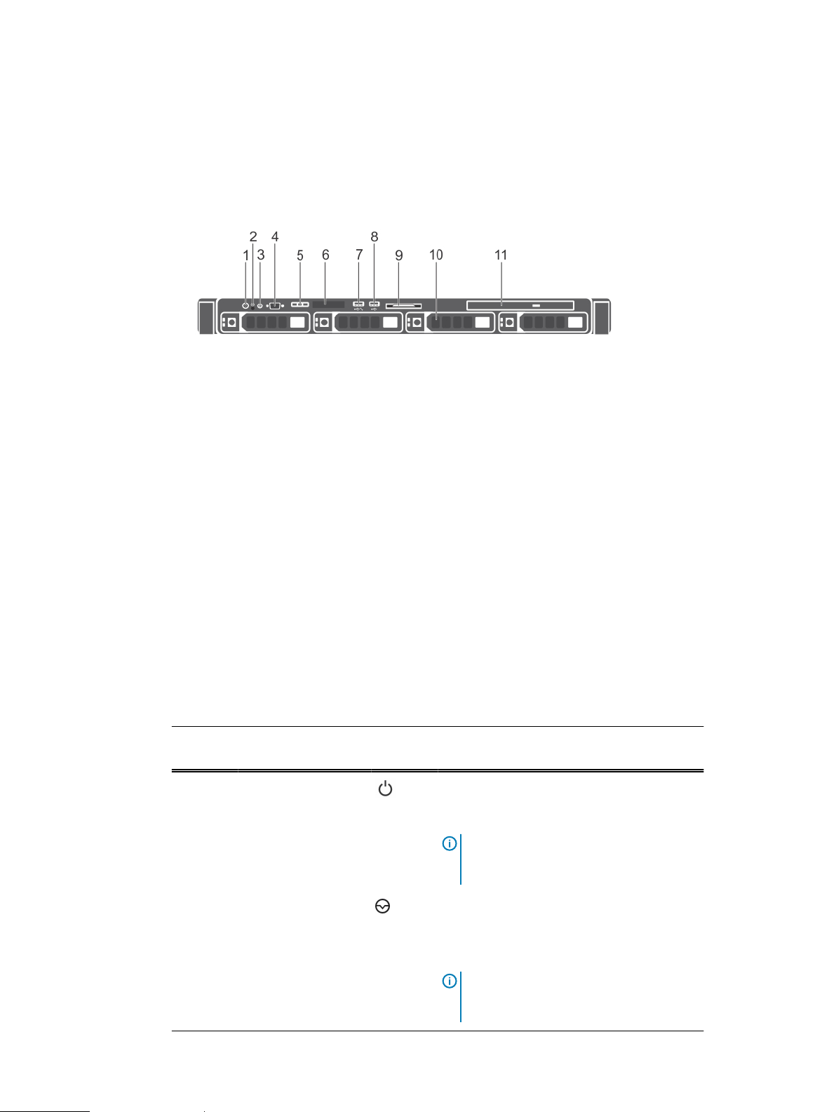
Front panel features of a 4 x 3.5-inch hard drive system
Figure 2 Front panel features of a 4 x 3.5-inch hard drive system
1. Power button
2. NMI button
3. System identification button
4. Video connector
5. LCD menu buttons
6. LCD panel
7. USB management port/iDRAC managed USB port
8. USB port
9. Information tag
10. Hard drives
11. Optical drive (optional)
Dell PowerEdge R430 system overview
This table describes about front panel features of a 4 x 3.5-inch hard drive system
Table 1
Front panel features of a 4 x 3.5-inch hard drive system
Item Indicator, Button, or
Connector
1 Power button Press the power button to turn the system on
2 NMI button Press the NMI button to troubleshoot
Icon Description
or off. The indicator on the button indicates if
the system is on or off.
Note: To gracefully shut down an ACPI-
compliant operating system, press the
power button.
software and device driver errors when
running certain operating systems. Use the
end of a paper clip to press the NMI button.
Note: Use the NMI button only if directed
to do so by qualified support personnel or
by the operating system documentation.
Dell PowerEdge R430 Owner's Manual 11

Dell PowerEdge R430 system overview
Table 1 Front panel features of a 4 x 3.5-inch hard drive system (continued)
Item Indicator, Button, or
Icon Description
Connector
3 System identification
button
Press the system ID button:
l
To locate a particular system within a
rack.
l
To turn the system ID on or off.
To reset iDRAC, press and hold the button for
more than 15 seconds.
Note: To reset iDRAC using system ID,
ensure that the system ID button is
enabled in the iDRAC setup.
Note: If the system stops responding
during POST, press and hold the system
ID button (for more than five seconds) to
enter the BIOS progress mode.
4 Video connector Use the video/VGA port to connect a display
to the system. For more information about the
supported video/VGA port, see the Technical
specifications section.
5 LCD menu buttons Press the LCD menu buttons to navigate the
control panel LCD menu.
6 LCD panel Displays system ID, status information, and
system error messages. For more information,
see the LCD panel section.
Note: LCD panel is not available in a
cabled hard drive system.
7 USB management
port/iDRAC managed
USB port
The USB management port is USB 2.0
compliant. Enables you to connect USB
devices to the system or provides access to
the iDRAC Direct features. For more
information, see the Integrated Dell Remote
Access Controller User’s Guide at Dell.com/
idracmanuals.
8 USB port Use the USB 2.0 port to connect USB devices
to the system. This port is 4-pin, USB 2.0
compliant.
9 Information tag Displays system information such as service
tag, NIC, and MAC address.
Note: The information tag is a slide-out
label panel.
10 Hard drives Up to four 3.5-inch hard drives or solid state
drives (SSD).
12 Dell PowerEdge R430 Owner's Manual
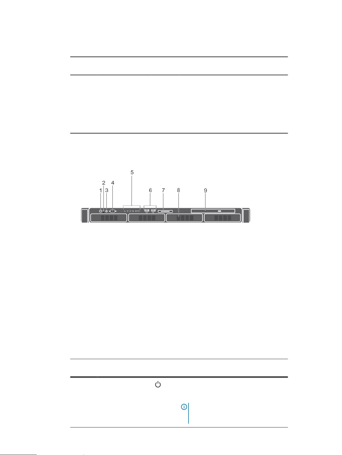
Table 1 Front panel features of a 4 x 3.5-inch hard drive system (continued)
Dell PowerEdge R430 system overview
Item Indicator, Button, or
Connector
11 Optical drive
(optional)
Icon Description
For information about the supported hard
drives, see the Technical specifications
section.
One optional slim SATA DVD-ROM drive or
DVD+/-RW drive.
For information about the supported optical
drive, see the Technical specifications section.
Front panel features of the 4 x 3.5-inch cabled hard drive system
Figure 3 Front panel features of the 4 x 3.5 inch cabled hard drive system
1. Power button
2. NMI button
3. System identification button
4. Video connector
5. Diagnostic indicators
6. USB port (2)
7. Information tag
8. Hard drives
9. Optical drive
Front panel features of the 4 x 3.5 inch cabled hard drive system
Table 2
Front panel features of the 4 x 3.5-inch cabled hard drive system
Item Indicator, Button, or
Connector
1 Power button Press the power button to turn the system on
Icon Description
or off. The indicator on the button indicates if
the system is on or off.
Note: To gracefully shut down an ACPI-
compliant operating system, press the
power button.
Dell PowerEdge R430 Owner's Manual 13

Dell PowerEdge R430 system overview
Table 2 Front panel features of the 4 x 3.5-inch cabled hard drive system (continued)
Item Indicator, Button, or
Icon Description
Connector
2 NMI button Press the NMI button to troubleshoot
software and device driver errors when
running certain operating systems. Use the
end of a paper clip to press the NMI button.
Note: Use the NMI button only if directed
to do so by qualified support personnel or
by the operating system documentation.
3 System identification
button
Press the system ID button:
l
To locate a particular system within a
rack.
l
To turn the system ID on or off.
To reset iDRAC, press and hold the button for
more than 15 seconds.
Note: To reset iDRAC using system ID,
ensure that the system ID button is
enabled in the iDRAC setup.
Note: If the system stops responding
during POST, press and hold the system
ID button (for more than five seconds) to
enter the BIOS progress mode.
4 Video connector Use the video/VGA port to connect a display
to the system. For more information about the
supported video/VGA port, see the Technical
specifications section.
5 Diagnostic indicators The diagnostic indicators light up to display
error status.
6 USB port (2) Use the USB 2.0 port to connect USB devices
to the system. This port is 4-pin, USB 2.0
compliant.
7 Information tag Displays system information such as service
tag, NIC, and MAC address.
Note: The information tag is a slide-out
label panel.
8 Hard drives Up to 4 x 3.5 inch cabled hard drives.
For information about the supported hard
drives, see the Technical specifications
section.
9 Optical drive
(optional)
One optional slim SATA DVD-ROM drive or
DVD+/-RW drive.
For information about the supported optical
drive, see the Technical specifications
section.
14 Dell PowerEdge R430 Owner's Manual
Dell PowerEdge R430 system overview
Front panel features of the 8 x 2.5 inch hard drives or SSDs system
Figure 4 Front panel features of a 8 x 2.5 inch hard drives or SSDs system
1. Power button
2. NMI button
3. System identification button
4. USB management port or iDRAC managed USB port
5. USB port
6. Optical drive
7. LCD menu buttons
8. Information tag
9. LCD panel
10. Video connector
11. Hard drives
This table describes the front panel features of a 8 x 2.5 inch hard drives or SSDs
Table 3
Front panel features of a 8 x 2.5 inch hard drives or SSDs system
Item Indicator, Button, or
Connector
1 Power button Press the power button to turn the system on
2 NMI button
3 System identification
button
Icon Description
or off. The indicator on the button indicates if
the system is on or off.
Note: To gracefully shut down an ACPI-
compliant operating system, press the
power button.
Press the NMI button to troubleshoot
software and device driver errors when
running certain operating systems. Use the
end of a paper clip to press the NMI button.
Note: Use the NMI button only if directed
to do so by qualified support personnel or
by the operating system documentation.
Press the system ID button:
Dell PowerEdge R430 Owner's Manual 15

Dell PowerEdge R430 system overview
Table 3 Front panel features of a 8 x 2.5 inch hard drives or SSDs system (continued)
Item Indicator, Button, or
Connector
4 USB management
port or iDRAC
managed USB port
Icon Description
l
To locate a particular system within a
rack.
l
To turn the system ID on or off.
To reset iDRAC, press and hold the button for
more than 15 seconds.
Note: To reset iDRAC using system ID,
ensure that the system ID button is
enabled in the iDRAC setup.
Note: If the system stops responding
during POST, press and hold the system
ID button (for more than five seconds) to
enter the BIOS progress mode.
The USB management port is USB 2.0
compliant. Enables you to connect USB
devices to the system or provides access to
the iDRAC Direct features. For more
information, see the Integrated Dell Remote
Access Controller User’s Guide at Dell.com/
idracmanuals.
5 USB port Use the USB 2.0 port to connect USB devices
to the system. This port is 4-pin, USB 2.0
compliant.
6 Optical drive
(optional)
One optional slim SATA DVD-ROM drive or
DVD+/-RW drive.
7 LCD menu buttons Press the LCD menu buttons to navigate the
control panel LCD menu.
8 Information tag Displays system information such as service
tag, NIC, and MAC address.
Note: The information tag is a slide-out
label panel.
9 LCD panel
Displays system ID, status information, and
system error messages. For more information,
see the LCD panel section.
Note: LCD panel is not available in a
cabled hard drive system.
10 Video connector
Use the video/VGA port to connect a display
to the system. For more information about the
supported video/VGA port, see the Technical
specifications section.
11 Hard drives Up to 8 x 2.5-inch hard drives or SSDs.
16 Dell PowerEdge R430 Owner's Manual
Dell PowerEdge R430 system overview
Table 3 Front panel features of a 8 x 2.5 inch hard drives or SSDs system (continued)
Item Indicator, Button, or
Connector
Icon Description
For information about the supported hard
drives, see the Technical specifications
section.
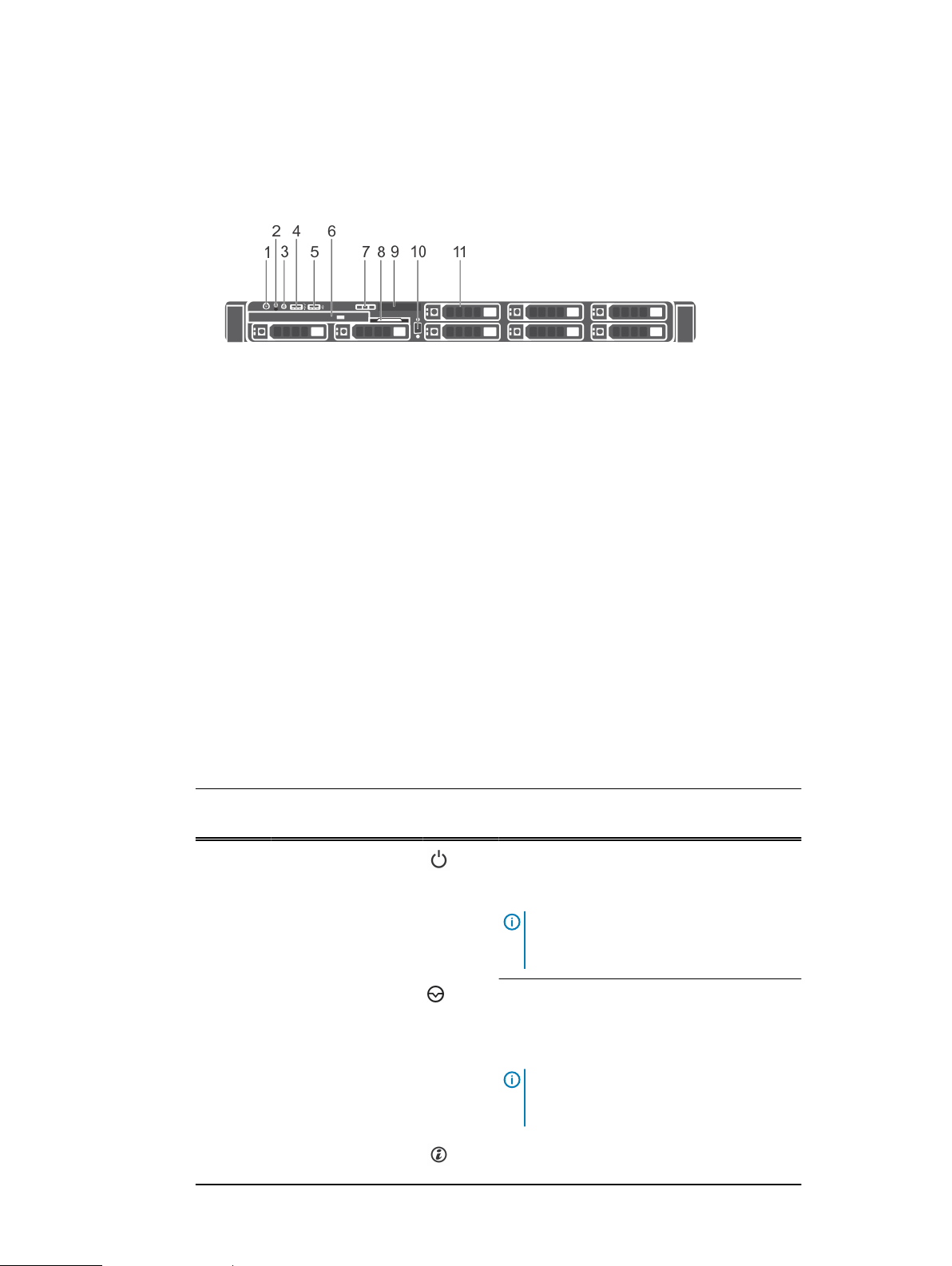
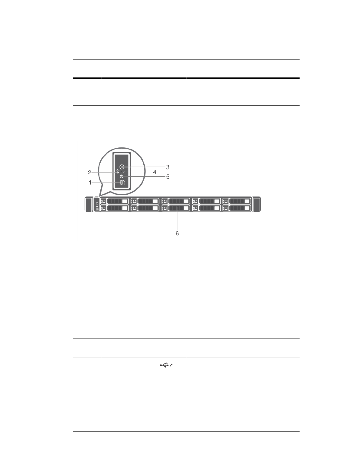
Front panel features of the 10 x 2.5-inch hard drives or SSDs system
Figure 5 Front panel features of the 10 x 2.5-inch hard drives or SSDs system
1. USB management port/iDRAC managed USB port
2. Diagnostic indicators
3. Power button
4. NMI button
5. System identification button
6. Hard drives
Front panel features of the 10 x 2.5-inch hard drives or SSDs system
Table 4
Front panel features of the 10 x 2.5-inch hard drives or SSDs system
Item Indicator, Button, or
Connector
1 USB management
port/iDRAC managed
USB port
2 Diagnostic indicators The diagnostic indicators light up to display
Icon Description
The USB management port is USB 2.0
compliant. Enables you to connect USB
devices to the system or provides access to
the iDRAC Direct features. For more
information, see the Integrated Dell Remote
Access Controller User’s Guide at Dell.com/
idracmanuals.
error status.
Dell PowerEdge R430 Owner's Manual 17

Dell PowerEdge R430 system overview
Table 4 Front panel features of the 10 x 2.5-inch hard drives or SSDs system (continued)
Item Indicator, Button, or
Connector
3 Power button Press the power button to turn the system on
4 NMI button Press the NMI button to troubleshoot
5 System identification
button
Icon Description
or off. The indicator on the button indicates if
the system is on or off.
Note: To gracefully shut down an ACPI-
compliant operating system, press the
power button.
software and device driver errors when
running certain operating systems. Use the
end of a paper clip to press the NMI button.
Note: Use the NMI button only if directed
to do so by qualified support personnel or
by the operating system documentation.
Press the system ID button:
l
To locate a particular system within a
rack.
l
To turn the system ID on or off.
To reset iDRAC, press and hold the button for
more than 15 seconds.
Note: To reset iDRAC using system ID,
ensure that the system ID button is
enabled in the iDRAC setup.
LCD panel
Note: If the system stops responding
during POST, press and hold the system
ID button (for more than five seconds) to
enter the BIOS progress mode.
6 Hard drives Up to 10 x 2.5 inch hard drives/SSDs.
For information about the supported hard
drives, see the Technical specifications
section.
The LCD panel of your system provides system information, status, and error messages to indicate
if the system is functioning correctly or if the system needs attention. For more information about
error messages, see the
Dell Event and Error Messages Reference Guide
at Dell.com/
openmanagemanuals >OpenManage software.
l
The LCD backlight turns blue during normal operating conditions.
l
When the system needs attention, the LCD turns amber, and displays an error code followed
by descriptive text.
Note:
If the system is connected to a power source and an error is detected, the LCD turns
amber regardless of whether the system is turned on or off.
l
The LCD backlight is turned off when the system is in standby mode and can be turned on by
pressing either the Select, Left, or Right button on the LCD panel.
18 Dell PowerEdge R430 Owner's Manual
Dell PowerEdge R430 system overview
l
The LCD backlight remains off if LCD messaging is turned off using the iDRAC utility, the LCD
panel, or other tools.
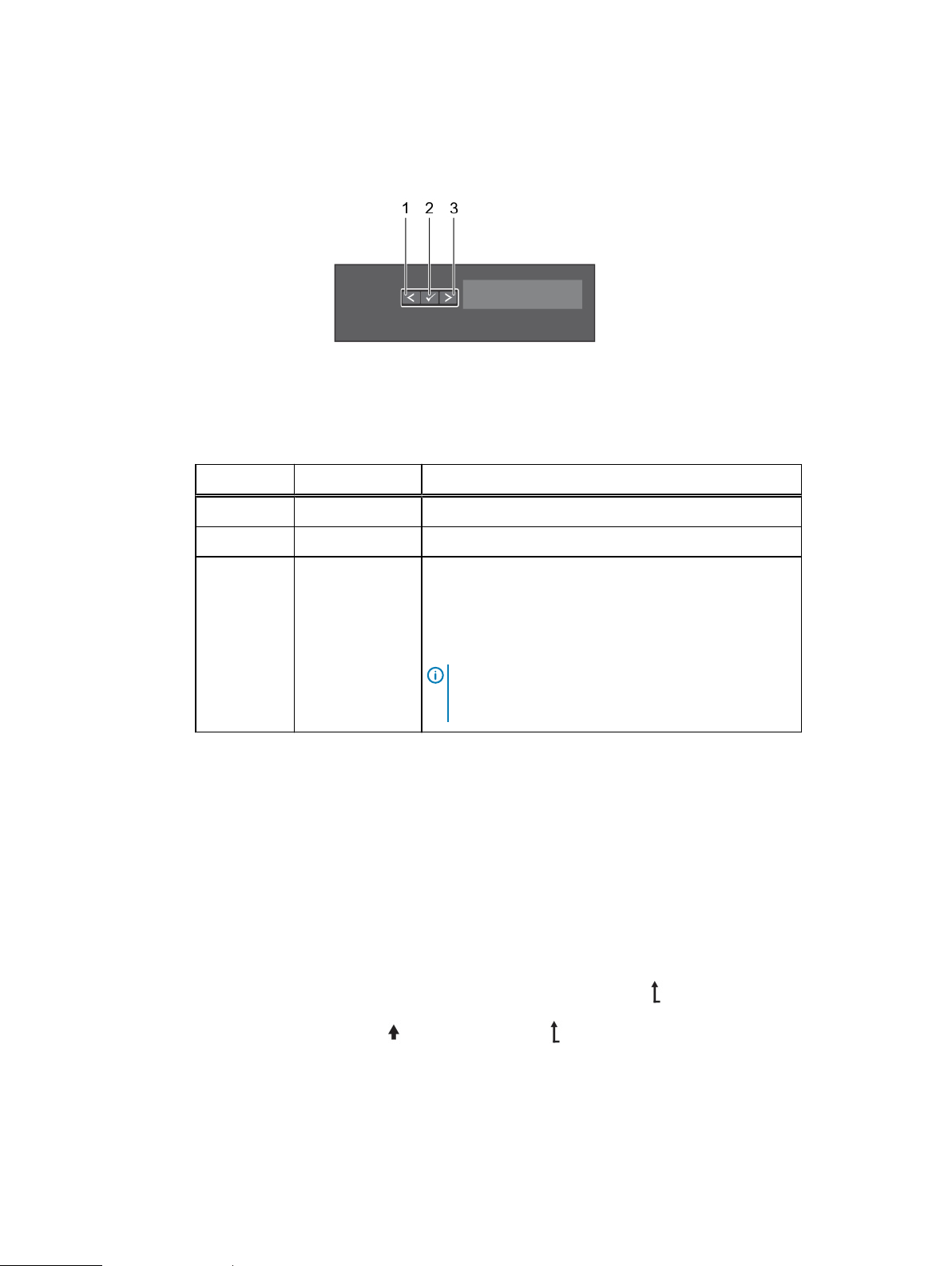
Figure 6 LCD panel features
The LCD Panel features table describes the LCD panel buttons: Left, Select and Right, and their
functions.
Table 5 LCD panel features
Item Button Description
1 Left Moves the cursor back in one-step increments.
2 Select Selects the menu item highlighted by the cursor.
3 Right Moves the cursor forward in one-step increments.
Viewing Home screen
The Home screen displays user-configurable information about the system. This screen is
displayed during normal system operation when there are no status messages or errors. When the
system is in standby mode, the LCD backlight turns off after a few minutes of inactivity, if there
are no error messages.
Procedure
1. To view the Home screen, press one of the three navigation buttons (Select, Left, or
2. To navigate to the Home screen from another menu, complete the following steps:
During message scrolling:
l
Press and hold the button to increase scrolling speed.
l
Release the button to stop.
Note: The display stops scrolling when the button is
released. After 45 seconds of inactivity the display
starts scrolling.
Right).
a.
Press and hold the navigation button till the up arrow is displayed.
b.
Navigate to the
using the up arrow
c. Select the Home icon.
d. On the Home screen, press the Select button to enter the main menu.
Dell PowerEdge R430 Owner's Manual 19

Dell PowerEdge R430 system overview
Setup menu
Note: When you select an option in the Setup menu, you must confirm the option before
proceeding to the next action.
Option
Description
iDRAC
Select DHCP or Static IP to configure the network mode. If Static IP is selected, the
available fields are IP, Subnet (Sub), and Gateway (Gtw). Select Setup DNS to enable DNS
and to view domain addresses. Two separate DNS entries are available.
Set error
Select SEL to view LCD error messages in a format that matches the IPMI description in the
SEL. This enables you to match an LCD message with an SEL entry.
Select Simple to view LCD error messages in a simplified user-friendly description. For more
information about error messages, see the
Dell.com/openmanagemanuals > OpenManage software.
Set home
Select the default information to be displayed on the Home screen. See View menu section
for the options and option items that can be set as the default on the Home screen.
Dell Event and Error Messages Reference Guide
at
View menu
Option
Description
Note:
When you select an option in the View menu, you must confirm the option before
proceeding to the next action.
iDRAC IP
Displays the IPv4 or IPv6 addresses for iDRAC8. Addresses include DNS (Primary and
Secondary), Gateway, IP, and Subnet (IPv6 does not have Subnet).
MAC
Displays the MAC addresses for iDRAC, iSCSI, or Network devices.
Name
Displays the name of the Host, Model, or User String for the system.
Number
Displays the Asset tag or the Service tag for the system.
Power
Displays the power output of the system in BTU/hr or Watts. The display format can be
configured in the Set home submenu of the Setup menu.
Temperature
Displays the temperature of the system in Celsius or Fahrenheit. The display format can be
configured in the Set home submenu of the Setup menu.
20 Dell PowerEdge R430 Owner's Manual
Back panel features
The back panel provides access to the features available on the back of the server, such as the
system identification button, power supply sockets, cable management arm connectors, iDRAC
storage media, NIC ports, and USB and VGA ports. A majority of the expansion card ports can be
accessed from the back panel. The hot swappable and cabled power supply units are accessible
from the back panel.
Redundant PSU back panel features
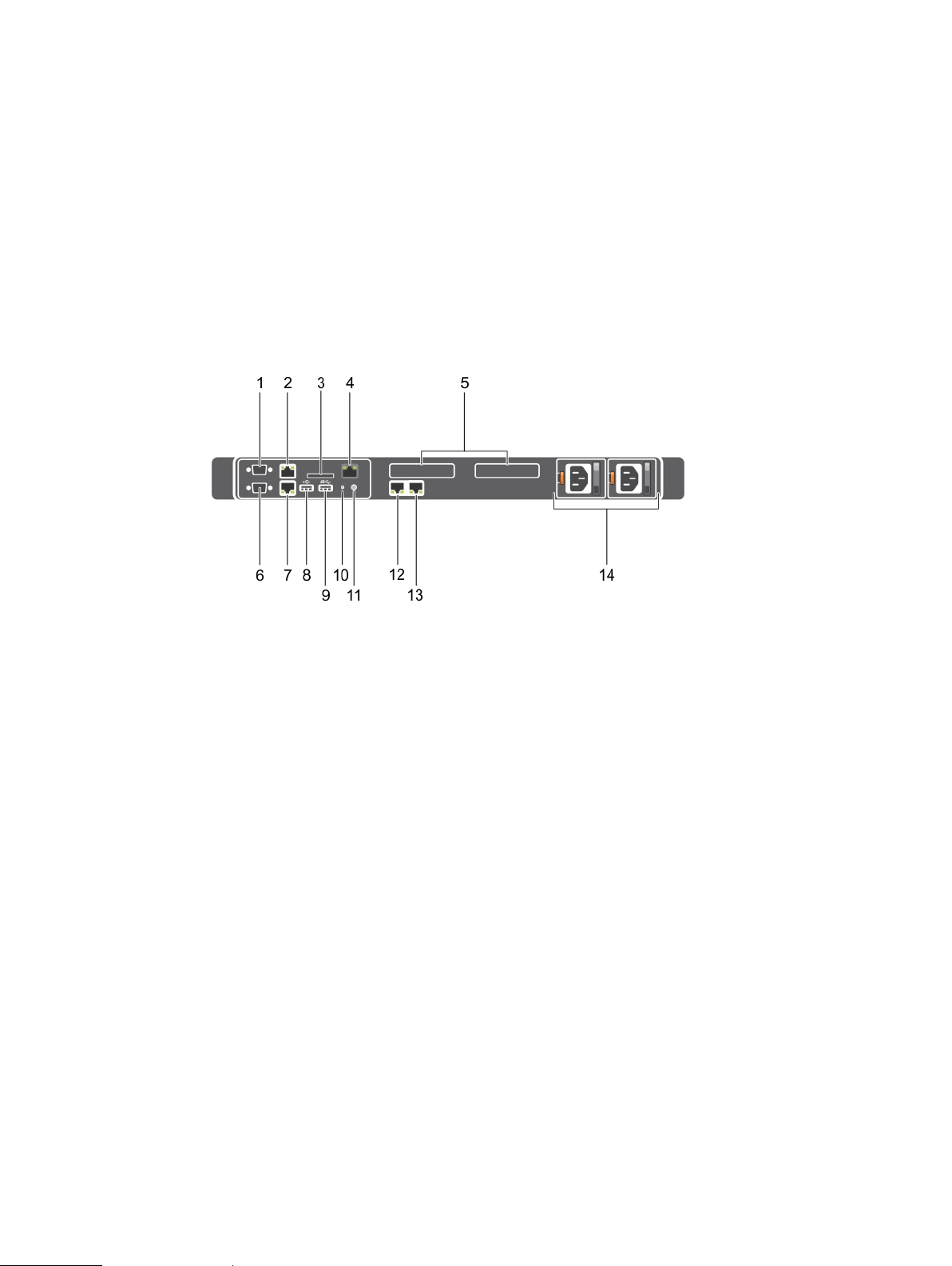
Figure 7 Redundant PSU back panel features
Dell PowerEdge R430 system overview
1. Serial connector
2. Ethernet connector 1
3. vFlash card slot (optional)
4. iDRAC port (optional)
5. PCIe expansion card slots (2)
6. Video connector
7. Ethernet connector 2
8. USB connector
9. USB connector
10. System identification button
11. System identification connector
12. Ethernet connector 3
13. Ethernet connector 4
14. Power supply unit (PSU1 and PSU2)
This table describes the redundant PSU back panel features. Item 1 is the serial connector, that
enables you to connect a serial device to the system. Item 2 is ethernet connector 1 that supports
10/100/1000 Mbps NIC connectors. Item 3 is the SD vFlash card slot that enables you to insert a
vFlash media card. Item 4 is the iDRAC8 Enterprise port. It is a dedicated management port. The
port is available for use only if the iDRAC8 Enterprise license is installed on your system. Item 5 is
the PCIe expansion card slot, that enables you to connect two low profile PCIe expansion cards.
Item 6 is the video connector, that enables you to connect a VGA display to the system. Item 7 is
ethernet connector 2 that supports 10/100/1000 Mbps NIC connectors. Item 8 is a USB 2.0
Dell PowerEdge R430 Owner's Manual 21

Dell PowerEdge R430 system overview
compliant port, that enables you to connect USB devices to the system. Item 9is a USB 3.0
compliant port, that enables you to connect USB devices to the system. Item 10 is the system
identification button on the front and back panels, that can be used to locate a particular system
within a rack. When one of these buttons is pressed, the LCD panel on the front and the system
status indicator on the back flashes until one of the buttons is pressed again. Press to toggle the
system ID on and off. If the system stops responding during POST, press and hold the system ID
button for more than five seconds to enter BIOS progress mode. To reset iDRAC (if not disabled in
F2 iDRAC setup) press and hold the button for more than 15 seconds. Item 11 is System
identification connector, that Enables you to connect the optional system status indicator
assembly through the optional cable management arm. Item 12 is ethernet connector 3 that
supports 10/100/1000 Mbps NIC connectors. Item 13 is ethernet connector 4 that supports
10/100/1000 Mbps NIC connectors. Item 14 are the power supply units (PSU1 and (PSU2) that are
AC PSU’s rated at 550 W.
Table 6 Redundant PSU back panel features
Item Indicator, Button, or
Connector
1 Serial connector Use the serial port to connect a serial device
2 Ethernet port 1 Use the Ethernet port to connect Local Area
3 vFlash card slot
(optional)
4 iDRAC port (optional) Use the iDRAC8 Enterprise port to remotely
5 PCIe expansion card
slots (2)
6 Video connector Use the video/VGA port to connect a display
Icon Description
to the system. For more information about the
supported serial port, see the Technical
specifications section.
Networks (LANs) to the system. For more
information about the supported Ethernet
ports, see the Technical specifications section.
Use the vFlash media card slot to insert a
vFlash media card.
access iDRAC. For more information, see the
Integrated Dell Remote Access Controller User’s
Guide
at Dell.com/idracmanuals.
Enables you to connect two PCI Express
expansion cards.
to the system. For more information about the
supported video/VGA port, see the Technical
specifications section.
7 Ethernet port 2 Use the Ethernet port to connect Local Area
8 USB port Use the USB 2.0 port to connect USB devices
9 USB port Use the USB 3.0 port to connect USB devices
22 Dell PowerEdge R430 Owner's Manual
Networks (LANs) to the system. For more
information about the supported Ethernet
ports, see the Technical specifications section.
to the system. This port is 4-pin, USB 2.0
compliant.
to the system. These ports are 9-pin, USB 3.0
compliant.
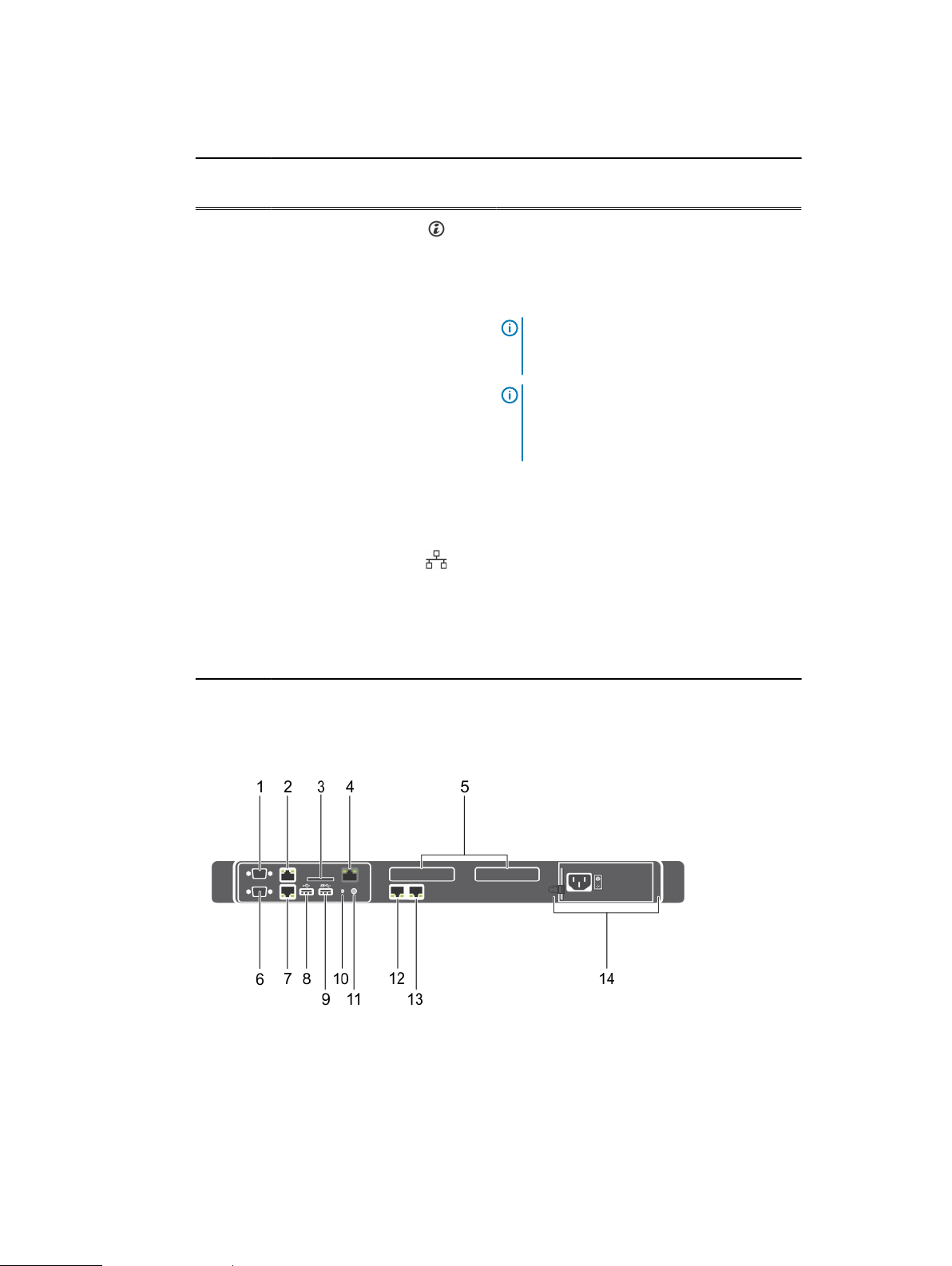
Table 6 Redundant PSU back panel features (continued)
Dell PowerEdge R430 system overview
Item Indicator, Button, or
Connector
10 System identification
button
11 System identification
port
12 Ethernet port 3 Use the Ethernet port to connect Local Area
13 Ethernet port 4
Icon Description
Press the system ID button:
l
To locate a particular system within a
rack.
l
To turn the system ID on or off.
Note: To reset the iDRAC (if not disabled
in F2 iDRAC setup), press and hold the
button for more than 15 seconds.
Note: If the system stops responding
during POST, press and hold the system ID
button (for more than five seconds) to
enter the BIOS progress mode.
Use the system identification port to connect
the system status indicator assembly through
the optional cable management arm.
Networks (LANs) to the system. For more
information about the supported Ethernet
ports, see the Technical specifications section.
14 Power supply unit
(PSU1 and PSU2)
Cabled PSU back panel features
Figure 8
Cabled PSU back panel features
1. Serial connector
2. Ethernet connector 1
3. vFlash card slot (optional)
4. iDRAC port (optional)
5. PCIe expansion card slots (2)
6. Video connector
Up to two 550 W redundant AC power
supplies.
Dell PowerEdge R430 Owner's Manual 23

Dell PowerEdge R430 system overview
Figure 8 Cabled PSU back panel features (continued)
7. Ethernet connector 2
8. USB connector
9. USB connector
10. System identification button
11. System identification connector
12. Ethernet connector 3
13. Ethernet connector 4
14. Cabled PSU
This table describes about Cabled PSU back panel features. Item 1 is the serial connector, that
enables you to connect a serial device to the system. Item 2 is ethernet connector 1 that supports
10/100/1000 Mbps NIC connectors. Item 3 is the SD vFlash card slot that enables you to insert a
vFlash media card. Item 4 is the iDRAC8 Enterprise port. It is a dedicated management port. The
port is available for use only if the iDRAC8 Enterprise license is installed on your system. Item 5 is
the PCIe expansion card slot, that enables you to connect two low profile PCIe expansion cards.
Item 6 is the video connector, that enables you to connect a VGA display to the system. Item 7 is
ethernet connector 2 that supports 10/100/1000 Mbps NIC connectors. Item 8 is a USB 2.0
compliant port, that enables you to connect USB devices to the system. Item 9is a USB 3.0
compliant port, that enables you to connect USB devices to the system. Item 10 is the system
identification button on the front and back panels, that can be used to locate a particular system
within a rack. When one of these buttons is pressed, the LCD panel on the front and the system
status indicator on the back flashes until one of the buttons is pressed again. Press to toggle the
system ID on and off. If the system stops responding during POST, press and hold the system ID
button for more than five seconds to enter BIOS progress mode. To reset iDRAC (if not disabled in
F2 iDRAC setup) press and hold the button for more than 15 seconds. Item 11 is System
identification connector, that Enables you to connect the optional system status indicator
assembly through the optional cable management arm. Item 12 is ethernet connector 3 that
supports 10/100/1000 Mbps NIC connectors. Item 13 is ethernet connector 4 that supports
10/100/1000 Mbps NIC connectors. Item 14 is the cabled AC PSU rated at 450 W.
Table 7
Cabled PSU back panel features
Item Indicator, Button, or
Connector
1 Serial connector Use the serial port to connect a serial device
2 Ethernet port 1 Use the Ethernet port to connect Local Area
3 vFlash card slot
(optional)
4 iDRAC port (optional) Use the iDRAC8 Enterprise port to remotely
24 Dell PowerEdge R430 Owner's Manual
Icon Description
to the system. For more information about the
supported serial port, see the Technical
specifications section.
Networks (LANs) to the system. For more
information about the supported Ethernet
ports, see the Technical specifications section.
Use the vFlash media card slot to insert a
vFlash media card.
access iDRAC. For more information, see the
Integrated Dell Remote Access Controller User’s
Guide
at Dell.com/idracmanuals.

Table 7 Cabled PSU back panel features (continued)
Dell PowerEdge R430 system overview
Item Indicator, Button, or
Icon Description
Connector
5 PCIe expansion card
slots (2)
Enables you to connect two PCI Express
expansion cards.
6 Video connector Use the video/VGA port to connect a display
to the system. For more information about the
supported video/VGA port, see the Technical
specifications section.
7 Ethernet port 2 Use the Ethernet port to connect Local Area
Networks (LANs) to the system. For more
information about the supported Ethernet
ports, see the Technical specifications section.
8 USB port Use the USB 2.0 port to connect USB devices
to the system. This port is 4-pin, USB 2.0
compliant.
9 USB port Use the USB 3.0 port to connect USB devices
to the system. These ports are 9-pin, USB 3.0
compliant.
10
System identification
button
Press the system ID button:
l
To locate a particular system within a
rack.
l
To turn the system ID on or off.
Note: To reset the iDRAC (if not disabled
in F2 iDRAC setup), press and hold the
button for more than 15 seconds.
Note: If the system stops responding
during POST, press and hold the system ID
button (for more than five seconds) to
enter the BIOS progress mode.
11 System identification
port
Use the system identification port to connect
the system status indicator assembly through
the optional cable management arm.
12 Ethernet port 3 Use the Ethernet port to connect Local Area
13 Ethernet port 4
Networks (LANs) to the system. For more
information about the supported Ethernet
ports, see the Technical specifications section.
14 Power supply unit
(PSU)
One 450 W cabled AC PSU.
Note: Cabled PSU is supported in systems
with cabled hard drives and the systems
with x4 backplane.
Dell PowerEdge R430 Owner's Manual 25
Dell PowerEdge R430 system overview
Diagnostic Indicators
The diagnostic indicators on the system front panel display error status during system startup.
Diagnostic indicators on the front panel
Note: The diagnostic indicators are not present if the system is equipped with an LCD display.
Note: No diagnostic indicators are lit when the system is turned off. To start the system, plug
it into a working power source and press the power button.
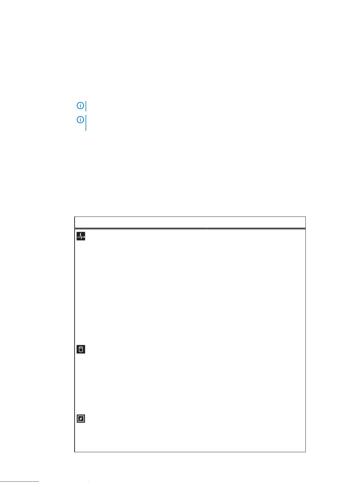
Item 1 is the health indicator, that indicates the health status of the system. The indicator turns
solid blue if the system is turned on and in good health. The indicator flashes amber if the system is
turned on or in standby, and if any issue occurs (for example, a failed fan or hard drive). Item 2 is
the hard drive indicator, that flashes amber if an error occurs related to hard drive. Item 3 is the
electrical indicator that flashes amber if an electrical error occurs (for example, voltage out of
range, or a failed power supply unit or voltage regulator). Item 4 is the temperature indicator that
flashes amber if a thermal error occurs (for example, a temperature out of range or fan failure).
Item 5 is the memory indicator that flashes amber if a memory error occurs. Item 6 is the PCIe
indicator that flashes amber if an error occurs related to PCIe card.
Table 8 Diagnostic indicators
Icon Description Condition Corrective action
Health
indicator
Hard drive
indicator
The indicator turns solid
blue if the system is in
good health.
The indicator flashes
amber:
l
When the system is
turned on.
l
When the system is
in standby.
l
If any error condition
exists. For example, a
failed fan, PSU, or a
hard drive.
The indicator flashes
amber if there is a hard
drive error.
None required.
Check the System Event Log or
system messages for the specific
issue. For more information about error
messages, see the
Messages Reference Guide
openmanagemanuals > OpenManage
software.
The POST process is interrupted
without any video output due to invalid
memory configurations. See the
Getting help section.
Check the System Event Log to
determine the hard drive that has an
error. Run the appropriate Online
Diagnostics test. Restart the system
and run embedded diagnostics (ePSA).
If the hard drives are configured in a
RAID array, restart the system and
enter the host adapter configuration
utility program.
Dell Event and Error
at Dell.com/
Electrical
indicator
26 Dell PowerEdge R430 Owner's Manual
The indicator flashes
amber if the system
experiences an electrical
error (for example,
voltage out of range, or a
Check the System Event Log or
system messages for the specific
issue. If it is due to a problem with the
PSU, check the LED on the PSU.
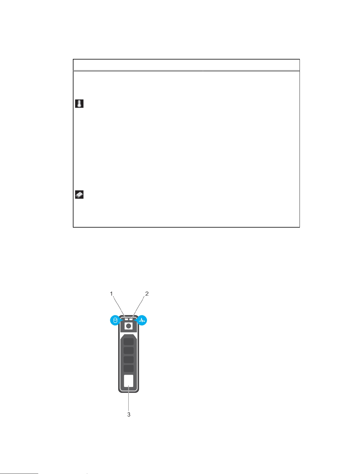
Table 8 Diagnostic indicators (continued)
Icon Description Condition Corrective action
Dell PowerEdge R430 system overview
Temperatur
e indicator
Memory
indicator
Hard drive indicator codes
failed power supply unit
(PSU) or voltage
regulator).
The indicator flashes
amber if the system
experiences a thermal
error (for example, the
ambient temperature is
out of range or fan
failure).
The indicator flashes
amber if a memory error
occurs.
Reseat the PSU. If the problem
persists, see the Getting help section.
Ensure that none of the following
conditions exist:
l
A cooling fan has been removed or
has failed.
l
System cover, cooling shroud, EMI
filler panel, memory module blank,
or back filler bracket is removed.
l
Ambient temperature is too high.
l
External airflow is obstructed.
See the Getting help section.
Check the system event log or system
messages for the location of the failed
memory. Reseat the memory module.
If the problem persists, see the Getting
help section.
Each hard drive carrier has an activity indicator and a status indicator. The indicators provide
information about the current status of the hard drive. The activity LED indicates whether hard
drive is currently in use or not. The status LED indicates the power condition of the hard drive.
Figure 9
Hard drive indicators
1. hard drive activity indicator
2. hard drive status indicator
Dell PowerEdge R430 Owner's Manual 27
Dell PowerEdge R430 system overview
Figure 9 Hard drive indicators (continued)
3. hard drive
Note: If the hard drive is in the Advanced Host Controller Interface (AHCI) mode, the status
indicator (on the right side) does not turn on.
The Hard drive indicator codes table describes the indicator codes: flashing green, steady green,
and amber.
Table 9 Hard drive indicator codes
Drive-status indicator pattern (RAID
only)
Flashes green twice per second Identifying drive or preparing for removal.
Off Drive ready for insertion or removal.
Flashes green, amber, and then turns off Predicted drive failure
Flashes amber four times per second Drive failed
Flashes green slowly Drive rebuilding
Steady green Drive online
Flashes green for three seconds, amber
for three seconds, and then turns off after
six seconds
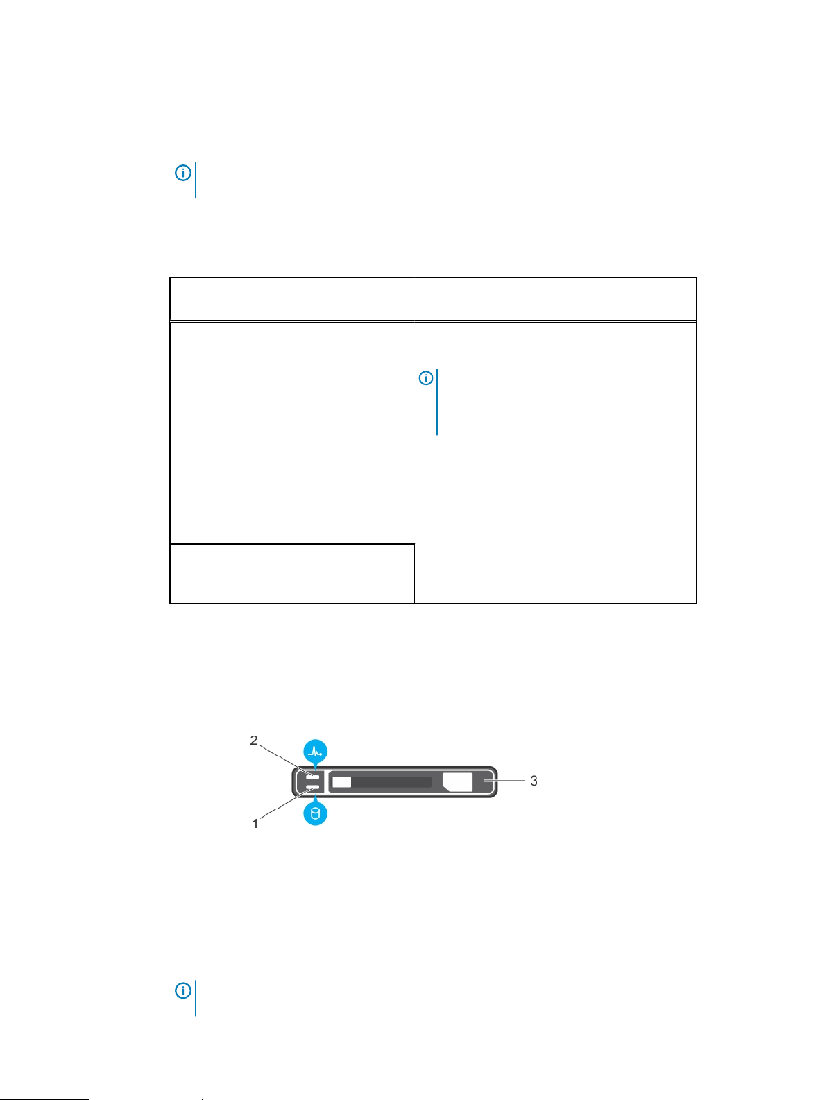
uSATA SSD indicator codes
Figure 10
uSATA SSD indicators
Condition
Note: The drive status indicator remains off
until all hard drives are initialized after the
system is turned on. Drives are not ready for
insertion or removal during this time.
Rebuild stopped
1. uSATA SSD activity indicator
2. uSATA SSD status indicator
3. uSATA SSD
Note: If the SSD is in the Advanced Host Controller Interface (AHCI) mode, the status
indicator (on the right side) does not function and remains off.
28 Dell PowerEdge R430 Owner's Manual
Dell PowerEdge R430 system overview
The following table contains the drive LED indicator pattern with the drive status.
Table 10 Drive status indicator codes
Drive-status indicator pattern Condition
Flashes green twice per second Identifying drive or preparing for removal.
Off Drive ready for insertion or removal.
Note: The drive status indicator remains off
until all hard drives are initialized after the
system is turned on. Drives are not ready for
insertion or removal during this time.
Flashes green, amber, and turns off Predicted drive failure
Flashes amber four times per second Drive failed
Steady green Drive online
Flashes green for three seconds, amber for
three seconds, and turns off after six
seconds
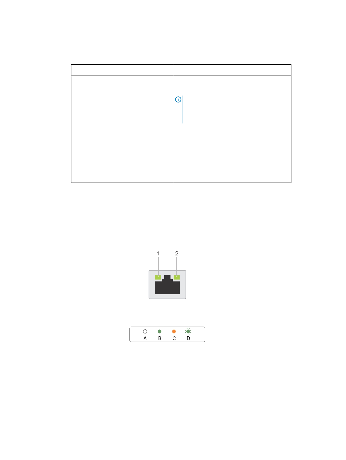
NIC indicator codes
Each NIC on the back panel has an indicator that provides information about the network activity
and link status. The activity LED indicates whether the NIC is currently connected or not. The link
LED indicates the speed of the connected network.
Figure 11
Rebuild aborted
NIC indicators
1. link indicator
2. activity indicator
The NIC indicators table describes different NIC indicator codes and condition of the connectivity.
Dell PowerEdge R430 Owner's Manual 29
Dell PowerEdge R430 system overview
Table 11 NIC indicators
Convention Status Condition
A Link and activity indicators are off The NIC is not connected to the
B Link indicator is green The NIC is connected to a valid
C Link indicator is amber The NIC is connected to a valid
D Activity indicator is flashing green Network data is being sent or
Internal dual SD module indicator codes
The Internal Dual SD module (IDSDM) provides you with a redundant SD card solution. You can
configure the IDSDM for storage or as the OS boot partition. The IDSDM card offers the following
features:
l
Dual card operation — maintains a mirrored configuration by using SD cards in both the slots
and provides redundancy.
Note:
When the Redundancy option is set to Mirror Mode in the Integrated Devices screen
of System Setup, the information is replicated from one SD card to another.
l
Single card operation — single card operation is supported, but without redundancy.
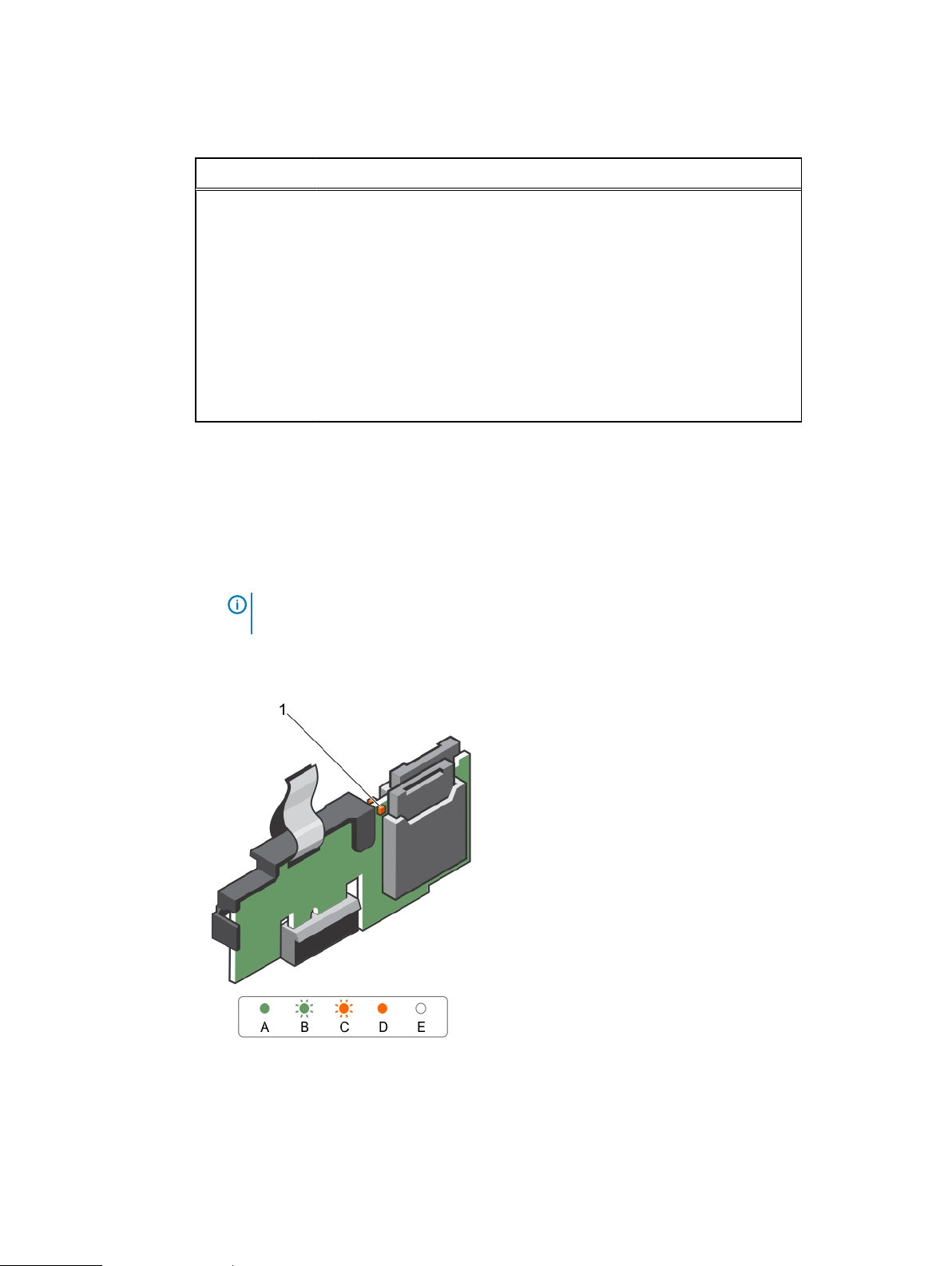
Figure 12
Internal dual SD module (IDSDM)
network.
network at its maximum port speed
(1 Gbps or 10 Gbps).
network at less than its maximum
port speed.
received.
1. LED status indicator (2)
The following table describes the IDSDM indicator codes:
The IDSDM indicator glows green when the card is online. The IDSDM indicator flashes green to
indicate rebuild or activity. The IDSDM indicator flashes amber to indicate card mismatch or that
30 Dell PowerEdge R430 Owner's Manual
 Loading...