

Page 1

WIFI, LTE Card installation
Install the Virtual Edge Platform (VEP) WIFI carrier cards with the replacement kit supplied. To
complete this installation, use the included standoffs, also known as spacers, and screws
found in the replacement kit.
CAUTION: To avoid electrostatic discharge (ESD) damage, wear grounding wrist straps
when handling this equipment.
WARNING: Customers are not to attempt installing Virtual Edge Platform (VEP) 4600
expansion cards. A Dell EMC Certified technician must perform this installation.
The VEP4600 WIFI carrier card is required to install the validated WIFI/LTE card into the
VEP4600 for customers who desire additional ports for their VEP4600. The VEP4600 WIFI
carrier card and the WIFI/LTE card will all ship separately from the VEP4600, so before
beginning the installation, ensure you have all required devices:
• VEP4600
• VEP4600 WIFI carrier card kit, including bag with standoffs and two screws
• WIFI/LTE card kit
NOTE: The VEP4600 WIFI carrier card is not attached to the WIFI/LTE card when it ships
to the customer.
1 Remove the VEP4600 top cover 10 screws and retain the screws from the top cover.
Page 2

Figure 40. Top cover removal
2 Remove and retain the two screws from the bottom of the chassis.
NOTE: Must retain top and bottom screws.
Page 3
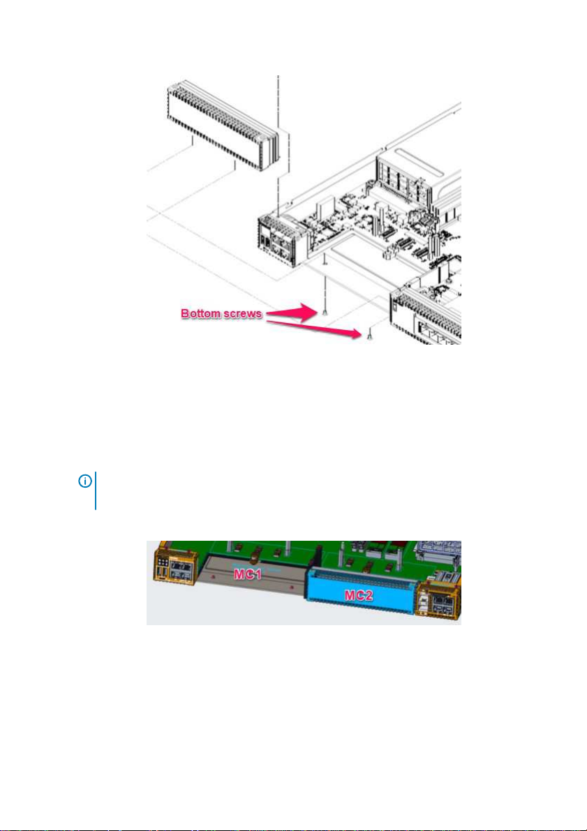
Figure 41. Blank front panel bottom screws
3 Decide which VEP4600 WIFI carrier card slot MC1 or MC2, or both, to install the WIFI
carrier card card(s) per customer order.
4 Pull-up the blank panel from either location MC1 or MC2(s) VEP4600 WIFI carrier card
slot.
NOTE: Do not leave an VEP4600 WIFI carrier card slot empty. Either a blank
panel or installed VEP4600 WIFI carrier card must be installed.
The following steps explain how-to install a VEP4600 WIFI carrier card in slot MC1.
Figure 42. MC1 blank panel location
5 Remove the right pin guide labeled Remove guide pin in the MC1 VEP4600 WIFI carrier
card slot. See the following figure.
Page 4
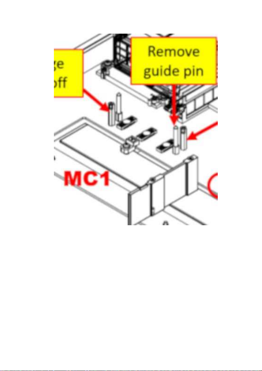
Figure 43. Remove guide pin
6 Remove the two standoffs labeled Change standoff in the MC1 VEP4600 WIFI carrier card
slot.
Page 5
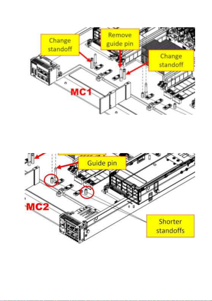
Figure 44. Change standoffs
7 Replace the removed standoffs in MC1 VEP4600 WIFI carrier card slot with the shorter
standoffs from the VEP4600 WIFI carrier card kit like MC2 in the following figure.
8 Be sure you have one guide pin and two shorter standoffs as shown in slot MC2.
Figure 45. VEP4600 WIFI carrier card guide pin and shorter standoffs
Page 6

9 Locate a WIFI or LTE card.
10 Install the WIFI or LTE card WITHOUT their antennas.
Page 7

Place the WIFI or LTE card into either MC1 or MC2 slot on the VEP4600.
Figure 46. LTE card without antennas
11
Page 8

WIFI carrier card with the guide pin installed on the
Figure 47. WIFI and LTE card in VEP4600
12 Align the hole on the VEP4600
motherboard.
Page 9

marked circular locations with two fingers with one hand and one
pointing finger.
Figure 48. Align WIFI/LTE card on guide pin
13 Push the three blue-
finger of the other hand at the image of a hand with a
Page 10

Figure 49. Installation finger push locations
14 Remove the two screws from the installation kit. 15 Install the two screws into the
shorter standoffs.
Page 11

the VEP4600 WIFI carrier card is fully
install the top ten cover screws.
Figure 50. WIFI, GTE screw locations
16 Re-install the two screws from bottom chassis so
connected to the chassis.
17 Replace the cover on the unit and re-
Page 12

Figure 51. Place the top cover back on the unit
Page 13

Industry Canada statement:
This device complies with ISED’s licence-exempt RSSs. Operation is subject to the following two
conditions: (1) This device may not cause harmful interference, and (2) this device must accept
any interference received, including interference that may cause undesired operation.
Le présent appareil est conforme aux CNR d’ ISED applicables aux appareils radio exempts de
licence. L’exploitation est autorisée aux deux conditions suivantes : (1) le dispositif ne doit pas
produire de brouillage préjudiciable, et (2) ce dispositif doit accepter tout brouillage reçu, y
compris un brouillage susceptible de provoquer un fonctionnement indésirable.
Radiation Exposure Statement:
This equipment complies with ISED radiation exposure limits set forth for an uncontrolled
environment. This equipment should be installed and operated with greater than 20cm
between the radiator & your body.
Déclaration d'exposition aux radiations:
Cet équipement est conforme aux limites d'exposition aux rayonnements ISED établies pour un
environnement non contrôlé. Cet équipement doit être installé et utilisé à plus de 20 cm entre
le radiateur et votre corps.
Page 14

This device is intended only for OEM integrators under the following
conditions: (For module device use)
The antenna must be installed and operated with greater than 20cm between the antenna and
users, and
2) The transmitter module may not be co-located with any other transmitter or antenna.
As long as 2 conditions above are met, further transmitter test will not be required. However,
the OEM integrator is still responsible for testing their end-product for any additional
compliance requirements required with this module installed.
Cet appareil est conçu uniquement pour les intégrateurs OEM dans les
conditions suivantes: (Pour utilisation de dispositif module)
1) L'antenne doit être installé et exploité avec plus de 20 cm entre l'antenne et les
utilisateurs, et
2) Le module émetteur peut ne pas être coïmplanté avec un autre
émetteur ou antenne.
Tant que les 2 conditions ci-dessus sont remplies, des essais supplémentaires sur l'émetteur ne
seront pas nécessaires. Toutefois, l'intégrateur OEM est toujours responsable des essais sur
son produit final pour toutes exigences de conformité supplémentaires requis pour ce module
installé.
IMPORTANT NOTE:
In the event that these conditions can not be met (for example certain laptop configurations or
co-location with another transmitter), then the Canada authorization is no longer considered
valid and the IC ID can not be used on the final product. In these circumstances, the OEM
integrator will be responsible for re-evaluating the end product (including the transmitter) and
obtaining a separate Canada authorization.
NOTE IMPORTANTE:
Dans le cas où ces conditions ne peuvent être satisfaites (par exemple pour certaines
configurations d'ordinateur portable ou de certaines co-localisation avec un autre émetteur),
l'autorisation du Canada n'est plus considéré comme valide et l'ID IC ne peut pas être utilisé
sur le produit final. Dans ces circonstances, l'intégrateur OEM sera chargé de réévaluer le
produit final (y compris l'émetteur) et l'obtention d'une autorisation distincte au Canada.
Page 15

End Product Labeling
This transmitter module is authorized only for use in device where the antenna may be
installed and operated with greater than 20cm between the antenna and users. The final end
product must be labeled in a visible area with the following: “Contains IC:1514B-E25W001”.
Plaque signalétique du produit final
Ce module émetteur est autorisé uniquement pour une utilisation dans un appareil où
l’antenne peut être installée et utilisée à plus de 20 cm entre l’antenne et les utilisateurs. Le
produit final doit être étiqueté dans un endroit visible avec l'inscription suivante: "Contient des
IC: 1514B-E25W001".
Manual Information To the End User
The OEM integrator has to be aware not to provide information to the end user regarding how
to install or remove this RF module in the user’s manual of the end product which integrates
this module.
The end user manual shall include all required regulatory information/warning as show in this
manual.
Manuel d'information à l'utilisateur final
L'intégrateur OEM doit être conscient de ne pas fournir des informations à l'utilisateur final
quant à la façon d'installer ou de supprimer ce module RF dans le manuel de l'utilisateur du
produit final qui intègre ce module.
Le manuel de l'utilisateur final doit inclure toutes les informations réglementaires requises et
avertissements comme indiqué dans ce manuel.
Page 16

DETACHABLE ANTENNA USAGE
This radio transmitter (IC: 1514B-E25W001/ Model: E25W, E25W001) has been approved by
ISED to operate with the antenna type listed below with maximum permissible gain indicated.
Antenna types not included in this list, having a gain greater than the maximum gain indicated
for that type, are strictly prohibited for use with this device.
Le présent émetteur radio (IC: 1514B-E25W001/ Model: E25W, E25W001) a été approuvé par
ISED pour fonctionner avec les types d'antenne énumérés ci-dessous et ayant un gain
admissible maximal. Les types d'antenne non inclus dans cette liste, et dont le gain est
supérieur au gain maximal indiqué, sont strictement interdits pour l'exploitation de l'émetteur.
Approved antenna(s) list
Type Gain
Dipole 2.0dBi
Page 17

Federal Communication Commission Interference
Statement
This device complies with Part 15 of the FCC Rules. Operation is subject to the
following two conditions: (1) This device may not cause harmful interference, and (2)
this device must accept any interference received, including interference that may
cause undesired operation.
This equipment has been tested and found to comply with the limits for a Class B
digital device, pursuant to Part 15 of the FCC Rules. These limits are designed to
provide reasonable protection against harmful interference in a residential
installation. This equipment generates, uses and can radiate radio frequency energy
and, if not installed and used in accordance with the instructions, may cause harmful
interference to radio communications. However, there is no guarantee that
interference will not occur in a particular installation. If this equipment does cause
harmful interference to radio or television reception, which can be determined by
turning the equipment off and on, the user is encouraged to try to correct the
interference by one of the following measures:
- Reorient or relocate the receiving antenna.
- Increase the separation between the equipment and receiver.
- Connect the equipment into an outlet on a circuit different from that
to which the receiver is connected.
- Consult the dealer or an experienced radio/TV technician for help.
FCC Caution: Any changes or modifications not expressly approved by the party
responsible for compliance could void the user's authority to operate this equipment.
This transmitter must not be co-located or operating in conjunction with any other
antenna or transmitter.
Radiation Exposure Statement:
This equipment complies with FCC radiation exposure limits set forth for an
uncontrolled environment. This equipment should be installed and operated with
minimum distance 20cm between the radiator & your body.
Page 18

This device is intended only for OEM integrators under the following
conditions:
1) The antenna must be installed such that 20 cm is maintained between the
antenna and users, and
2) The transmitter module may not be co-located with any other transmitter or
antenna.
As long as 2 conditions above are met, further transmitter test will not be required.
However, the OEM integrator is still responsible for testing their end-product for any
additional compliance requirements required with this module installed
IMPORTANT NOTE: In the event that these conditions can not be met (for example
certain laptop configurations or co-location with another transmitter), then the FCC
authorization is no longer considered valid and the FCC ID can not be used on the
final product. In these circumstances, the OEM integrator will be responsible for
re-evaluating the end product (including the transmitter) and obtaining a separate
FCC authorization.
End Product
This transmitter module is authorized only for use in device where the antenna may
be installed such that 20 cm may be maintained between the antenna and users. The
final end product must be labeled in a visible area with the following: “Contains FCC
ID: E2K-E25W001”. The grantee's FCC ID can be used only when all FCC compliance
requirements are met.
Manual Information To the End User
The OEM integrator has to be aware not to provide information to the end user
regarding how to install or remove this RF module in the user’s manual of the end
product which integrates this module.
The end user manual shall include all required regulatory information/warning as
show in this manual.
Labeling
Page 19

低功率電波輻射性電機管理辦法
第十二條 經型式認證合格之低功率射頻電機,非經許可,
公司、商號或使用者均不得擅自變更頻率、加大
功率或變更原設計之特性及功能。
第十四條 低功率射頻電機之使用不得影響飛航安全及干
擾合法通信;經發現有干擾現象時,應立即停用,
並改善至無干擾時方得繼續使用。
前項合法通信,指依電信法規定作業之無線電通
信。
低功率射頻電機須忍受合法通信或工業、科學及
醫療用電波輻射性電機設備之干擾。
 Loading...