

Dell E2414Hr, E2414Ht User Manual

User’s Guide
Dell E2414H
Dell E2414Hr
Model No.: E2414H/E2414Hr
Regulatory model: E2414Ht

3
NOTE: A NOTE indicates important information that helps you make
better use of your computer.
CAUTION: A CAUTION indicates potential damage to hardware or loss
of data if instructions are not followed.
WARNING: A WARNING indicates a potential for property damage,
personal injury, or death.
© 2013 Dell Inc. All rights reserved.
Information in this document is subject to change without notice.
Reproduction of these materials in any manner whatsoever without the
written permission of Dell Inc. is strictly forbidden.
Trademarks used in this text: Dell™, the DELL logo, and Inspiron™ are
trademarks of Dell Inc.; Intel
®
, Centrino®, Core™, and Atom™ are either
trademarks or registered trademarks of Intel Corporation in the U.S. and
other countries; Microsoft®, Windows®, and Windows start button logo
are either trademarks or registered trademarks of Microsoft Corporation
in the United States and/or other countries; Bluetooth® is a registered
trademark owned by Bluetooth SIG, Inc. and is used by Dell under license;
Blu-ray Disc™ is a trademark owned by the Blu-ray Disc Association(BDA)
and licensed for use on discs and players; Other trademarks and trade
names may be used in this document to refer to either the entities
claiming the marks and names or their products. Dell Inc. disclaims any
proprietary interest in trademarks and trade names other than its own.
2013 – 10 Rev. A00
Contents
About Your Monitor ..................................... 6
Package Contents . . . . . . . . . . . . . . . . . . . . . . . . . . . . . . . .6
Product Features . . . . . . . . . . . . . . . . . . . . . . . . . . . . . . . . .7
Identifying Parts and Controls . . . . . . . . . . . . . . . . . . . . . . . . .8
Front View . . . . . . . . . . . . . . . . . . . . . . . . . . . . . . . . . . . . . . . 8
Back View . . . . . . . . . . . . . . . . . . . . . . . . . . . . . . . . . . . . . . . 9
Side View . . . . . . . . . . . . . . . . . . . . . . . . . . . . . . . . . . . . . . . . 9
Bottom View . . . . . . . . . . . . . . . . . . . . . . . . . . . . . . . . . . . . 10
Monitor Specifications . . . . . . . . . . . . . . . . . . . . . . . . . . . . 10
Flat Panel Specifications . . . . . . . . . . . . . . . . . . . . . . . . . . . . . 10
Resolution Specifications . . . . . . . . . . . . . . . . . . . . . . . . . . . . . .11
Video Supported Modes. . . . . . . . . . . . . . . . . . . . . . . . . . . . . . .11
Preset Display Modes . . . . . . . . . . . . . . . . . . . . . . . . . . . . . . . .11
Electrical Specifications . . . . . . . . . . . . . . . . . . . . . . . . . . . . . . .12
Physical Characteristics . . . . . . . . . . . . . . . . . . . . . . . . . . . . . . .12
Environmental Characteristics . . . . . . . . . . . . . . . . . . . . . . . . . . .13
Power Management Modes. . . . . . . . . . . . . . . . . . . . . . . . . . . . 14
Pin Assignments . . . . . . . . . . . . . . . . . . . . . . . . . . . . . . . . . . .15
Plug and Play Capability . . . . . . . . . . . . . . . . . . . . . . . . . . . 16
LCD Monitor Quality and Pixel Policy . . . . . . . . . . . . . . . . . . . 16
Maintenance Guidelines . . . . . . . . . . . . . . . . . . . . . . . . . . . 17
Cleaning Your Monitor . . . . . . . . . . . . . . . . . . . . . . . . . . . . . . .17
Setting Up the Monitor.................................. 18
Attaching the Stand . . . . . . . . . . . . . . . . . . . . . . . . . . . . . . 18
Connecting Your Monitor . . . . . . . . . . . . . . . . . . . . . . . . . . 18
Organizing the Cables . . . . . . . . . . . . . . . . . . . . . . . . . . . . 19
Attaching the Cable Cover . . . . . . . . . . . . . . . . . . . . . . . . . . 20
Removing the Stand . . . . . . . . . . . . . . . . . . . . . . . . . . . . . . 20
Wall Mounting (Optional). . . . . . . . . . . . . . . . . . . . . . . . . . . 21
Operating the Monitor .................................. 22
Using the Front Panel Controls . . . . . . . . . . . . . . . . . . . . . . . 22
Using the On-Screen Display (OSD) Menu. . . . . . . . . . . . . . . . . 24
OSD Warning Messages . . . . . . . . . . . . . . . . . . . . . . . . . . . . . . 37
Setting the Maximum Resolution . . . . . . . . . . . . . . . . . . . . . . 38
Using the Tilt . . . . . . . . . . . . . . . . . . . . . . . . . . . . . . . . . . 39
Tilt . . . . . . . . . . . . . . . . . . . . . . . . . . . . . . . . . . . . . . . . . . . 39
Troubleshooting .......................................40
Self-Test . . . . . . . . . . . . . . . . . . . . . . . . . . . . . . . . . . . . . 40
Built-in Diagnostics . . . . . . . . . . . . . . . . . . . . . . . . . . . . . . 41
Common Problems . . . . . . . . . . . . . . . . . . . . . . . . . . . . . . 42
Product Specific Problems . . . . . . . . . . . . . . . . . . . . . . . . . . 47

4 5
Appendix ..............................................49
WARNING: Safety Instructions. . . . . . . . . . . . . . . . . . . . . . . . 49
FCC Notices (U.S. Only) and Other Regulatory Information . . . . . . 49
Contacting Dell. . . . . . . . . . . . . . . . . . . . . . . . . . . . . . . . . 49
Setting Up Your Monitor ................................50
Setting the display resolution to 1920 x 1080 (maximum) . . . . . . . 50
If you have a Dell desktop or a Dell portable computer with internet
access . . . . . . . . . . . . . . . . . . . . . . . . . . . . . . . . . . . . . . 51
If you have non Dell desktop, portable computer, or graphic card . . 52
Procedures for setting up dual monitors in Windows Vista®, Windows
®
7 or Windows® 8 . . . . . . . . . . . . . . . . . . . . . . . . . . . . . . . . 53
6 About Your Monitor About Your Monitor 7
About Your Monitor
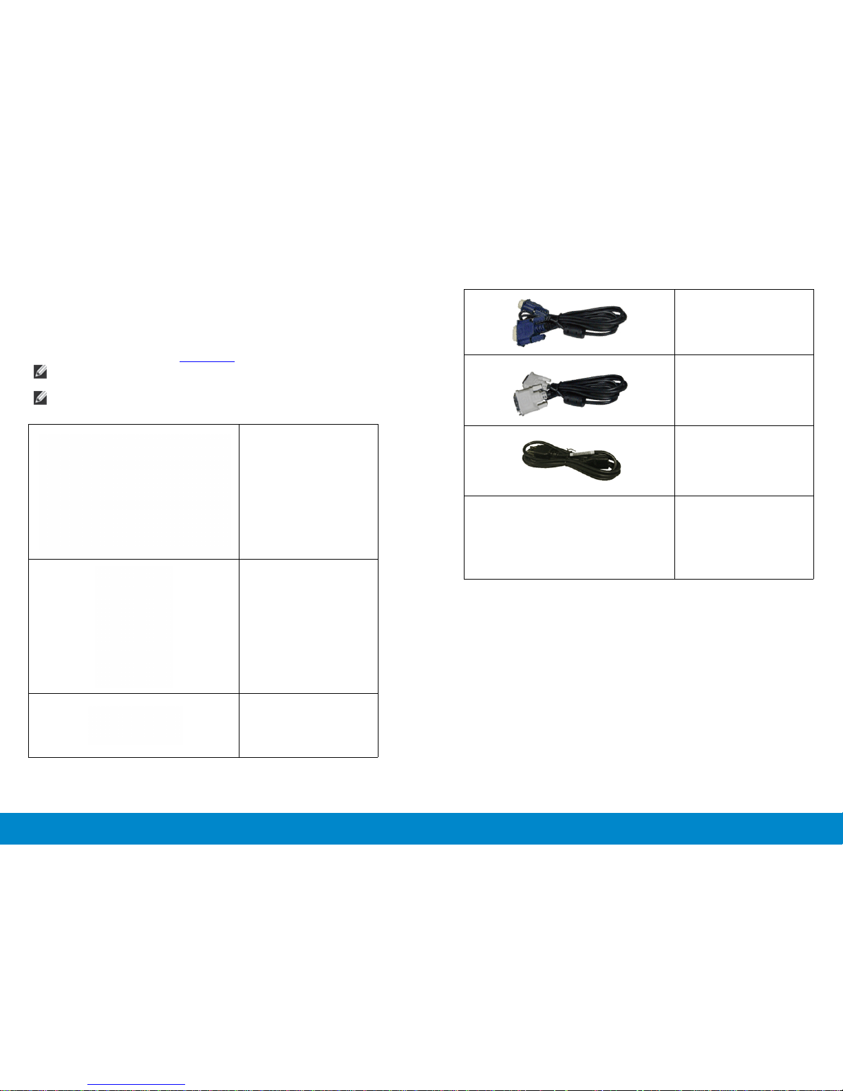
Package Contents
Your monitor ships with the components shown below. Ensure that you have
received all the components and contact Dell if something is missing.
NOTE: Some items may be optional and may not ship with your monitor.
Some features or media may not be available in certain countries.
NOTE: To set up with any other stand, please refer to the respective
stand setup guide for setup instructions.
• Monitor
• Stand
• Cable Cover
• VGA Cable
• DVI Cable (E2414H only)
• Power Cable (varies by
countries)
• Drivers and
Documentation media
• Quick Setup Guide
• Product and Safety
Information Guide
Product Features
The Dell E2414H/E2414Hr at panel display has an active matrix, thin-lm
transistor (TFT), liquid crystal display (LCD), and LED backlight. The monitor
features include:
• 60.97 cm (24-inch) active area display (Measured diagonally) 1920 x 1080
resolution, plus full-screen support for lower resolutions.
• Tilt adjustment capability.
• Removable pedestal and Video Electronics Standards Association (VESA™)
100 mm mounting holes for exible mounting solutions.
• Plug and play capability if supported by your system.
• On-Screen Display (OSD) adjustments for ease of set-up and screen
optimization.
• Software and documentation media includes an information le
(INF), Image color Matching File (ICM), Dell Display Manager software
application and product documentation. Dell Display Manager included
8 About Your Monitor About Your Monitor 9
(comes in the CD attached with the monitor).
Back View
• Security lock slot.
• Stand lock.
• Asset Management Capability.
• Energy Star Compliant.
• EPEAT Gold Compliant.
1
• RoHS compliant.
2
• BFR/PVC- reduced.
5
• Arsenic-Free glass and Mercury Free for Panel only.
3
4
• Energy Gauge shows the energy level being consumed by the monitor in
real time.
• TCO Certied Displays.
Back view Back view with monitor stand
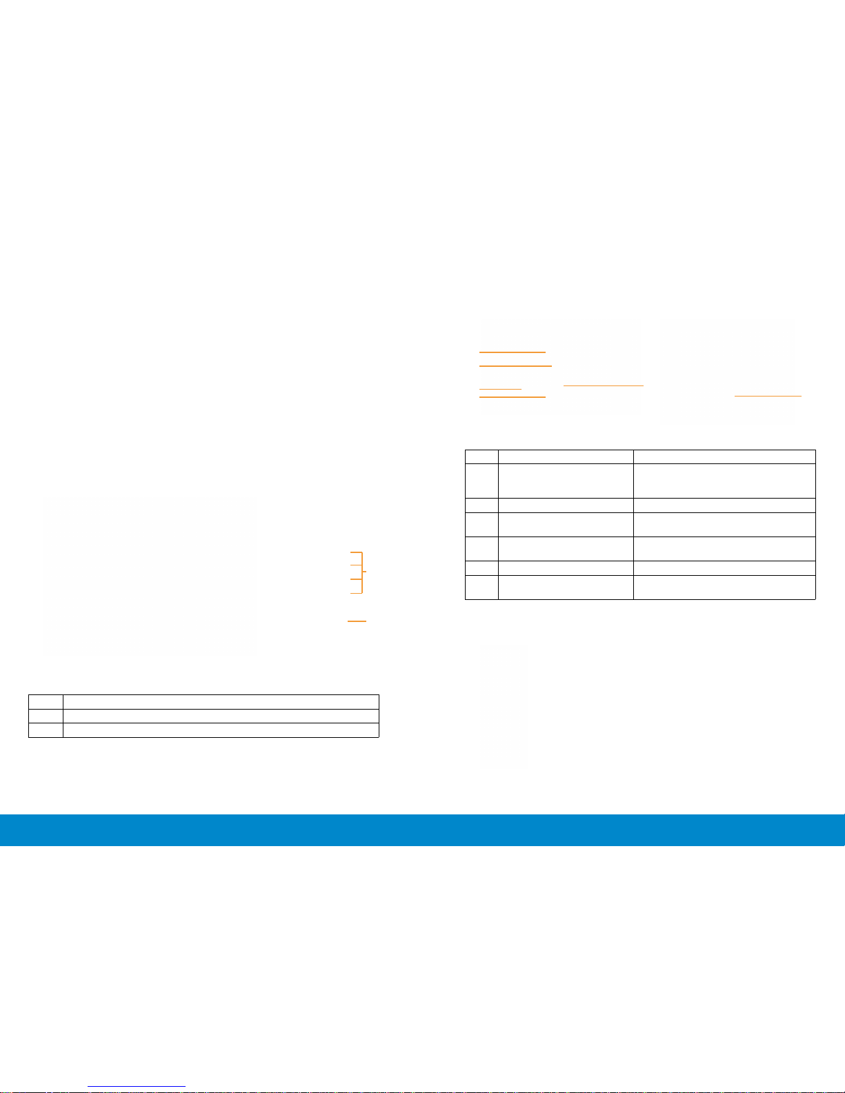
Identifying Parts and Controls
Front View
1
Label Description Use
1 VESA mounting holes (100
mm x 100 mm - behind attached VESA Cover)
Wall mount monitor using VESA-compatible wall mount kit (100 mm x 100
mm).
2 Regulatory label Lists the regulatory approvals.
3 Security lock slot Secures monitor with security lock.
(security lock not included)
4 Barcode serial number label Refer to this label if you need to con-
tact Dell for technical support.
5 Stand release button Release stand from monitor.
6 Cable management slot Use to organize cables by placing
them through the slot.
2
Side View
Front View Front panel controls
Label Description
1. Function buttons (For more information, see Operating the Monitor)
2. Power On/O button (with LED indicator)
6
10 About Your Monitor About Your Monitor 11
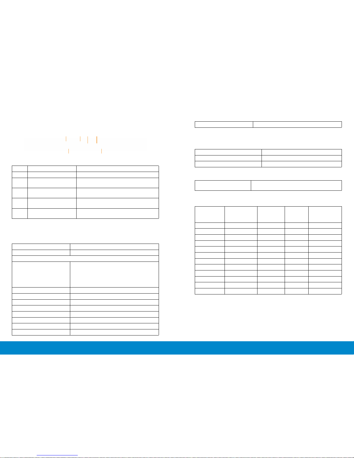
Bottom View
1 2 3 4
5 5
Bottom view
Label Description Use
1. AC power connector To connect the monitor power cable.
2. Stand lock To lock the stand to the monitor using a
M3 x 6mm screw (screw not included).
3 DVI connector To connect your computer to the moni-
tor using a DVI cable.
4 VGA connector To connect your computer to the moni-
tor using a VGA cable.
5 Dell Soundbar mounting
slots
Attaches the optional Dell Soundbar.
Monitor Specifications
Flat Panel Specifications
Screen type Active matrix - TFT LCD
Panel type TN
Viewable image
Diagonal
Horizontal Active Area
Vertical Active Area
Area
60.97 cm (24 inches)
531.36 mm (20.92 inches)
298.89 mm (11.77 inches)
158818.19 mm
2
(246.17 inch2)
Pixel pitch 0.277 mm
Viewing angle 160° (vertical) typ, 170° (horizontal) typ
Luminance output 250 cd/m ²(typ)
Contrast ratio 1000:1 (typ)
Faceplate coating Antiglare with hard-coating 3H
Backlight LED edgelight system
Response Time 5 ms typical
Color depth 16.7 million colors
Color gamut (Typical) 83%* (CIE1976)
*[E2414H/E2414Hr] color gamut (typical) is based on CIE1976 (83%) and
CIE1931 (72%) test standards.
Resolution Specifications
Horizontal scan range 30 kHz to 83 kHz (automatic)
Vertical scan range 56 Hz to 75 Hz (automatic)
Maximum resolution 1920 x 1080 at 60 Hz
Video Supported Modes
Video display capabilities
(DVI playback)
480p, 576p, 720p, 1080p and 1080i
Preset Display Modes
Display Mode Horizontal
Frequency
(kHz)
Vertical
Frequency
(Hz)
Pixel
Clock
(MHz)
Sync Polarity
(Horizontal/
Vertical)
720 x 400 31.5 70.0 28.3 -/+
640 x 480 31.5 60.0 25.2 -/640 x 480 37.5 75.0 31.5 -/800 x 600 37.9 60.0 40.0 +/+
800 x 600
46.9
75.0
49.5
+/+
1024 x 768
48 .4
60.0
65.0
-/-
1024 x 768 60.0 75.0 78.8 +/+
1152 x 864 67.5 75.0 108.0 +/+
1280 x 1024 64.0 60.0 108.0 +/+
1280 x 1024 80.0 75.0 135.0 +/+
1600 x 900
60.0
60.0
108.0
+/-
1920 x 1080
67. 5
60.0
148.5
+/+

12 About Your Monitor About Your Monitor 13
Electrical Specifications
Weight without stand assembly
(For wall mount or VESA mount 3.00 kg (6.75 lb)
considerations - no cables)
Weight of stand assembly 1.03 kg (2.27 lb)
Video input signals Analog RGB, 0.7 Volts +/-5%, positive polarity at
75 ohm input impedance
Digital DVI-D TMDS, 600mV for each
dierential line, positive polarity at 50 ohm input
impedance
Synchronization input
signals
Separate horizontal and vertical
synchronizations, polarity-free TTL level, SOG
(Composite SYNC on green)
AC input voltage/
frequency/current
100 to 240 VAC/50 or 60 Hz + 3 Hz/1.5 A (Max.)
Inrush current 120 V:30 A (Max.)
240 V:60 A (Max.)
Physical Characteristics
Connector type 15-pin D-subminiature, blue connec-
tor; DVI-D, white connector
Signal cable type Digital: Detachable, DVI-D (E2414H
only), Solid pins.
Analog: Detachable, D-Sub, 15 pins.
Dimensions (with stand)
Height 418.3 mm (16.47 inches)
Width 570.0 mm (22.44 inches)
Depth 164.2 mm (6.46 inches)
Dimensions (without stand)
Height 337.5 mm (13.29 inches)
Width 570.0 mm (22.44 inches)
Depth 46.5 mm (1.83 inches)
Stand dimensions
Height 318.7 mm (12.55 inches)
Width 180.6 mm (7.11 inches)
Depth 164.2 mm (6.46 inches)
Weight
Weight with packaging 5.87 kg (12.94 lb)
Weight with stand assembly and
cables
4.48 kg (9.88 lb)
Environmental Characteristics
Temperature
Operating 0 °C to 40 °C
Non-operating
Storage: -20 °C to 60°C (-4 °F to 140 °F)
Shipping: -20 °C to 60°C (-4 °F to 140 °F)
Humidity
Operating 10% to 80% (non-condensing)
Non-operating
Storage: 5% to 90% (non-condensing)
Shipping: 5% to 90% (non-condensing)
Altitude
Operating 5,000 m (16,400 ft) max
Non-operating 12,191 m (40,000 ft) max
Thermal dissipation
238.85 BTU/hour (maximum)
102.36 BTU/hour (typical)
Power Management Modes
If you have VESA’s DPM™ compliance display card or software installed
in your PC, the monitor can automatically reduce its power consumption
when not in use. This is referred to as Power Save Mode. If the computer
detects input from keyboard, mouse, or other input devices, the monitor
automatically resumes functioning. The following table shows the power
consumption and signaling of this automatic power saving feature:
VESA Modes Horizontal
Sync
Vertical
Sync
Video Power
Indicator
Power Consumption
Normal
operation
Active Active Active White 20 W (typical)/30 W
(maximum)
Active-o
mode
Inactive Inactive Blanked Glowing
White
Less than 0.5 W
Switch o - - - O Less than 0.5 W
The OSD will only function in the normal operation mode. When any button

14 About Your Monitor About Your Monitor 15
is pressed in Active-o mode, the following message will be displayed:
Activate the computer and the monitor to gain access to the OSD.
6 GND-R
7 GND-G
8 GND-B
9 Computer 5V/3.3V
10 GND-sync
11 GND
12 DDC data
13 H-sync
14 V-sync
15 DDC clock
DVI Connector
NOTE: This monitor is ENERGY STAR®-compliant.
NOTE: Zero power consumption in OFF mode can only be achieved by
disconnecting the main cable from the monitor.
Pin Assignments
VGA Connector
Pin Number 15-pin Side of the Connected Signal Cable
1 Video-Red
2 Video-Green
3 Video-Blue
4 GND
5 Self-test
Pin Number 24-pin Side of the Connected Signal Cable
1 TMDS RX22 TMDS RX2+
3 TMDS Ground
4 Floating
5 Floating
6 DDC Clock
7 DDC Data
8 Floating
9 TMDS RX110 TMDS RX1+
11 TMDS Ground
12 Floating
16 About Your Monitor Setting Up the Monitor 17
13 Floating
14 +5V/+3.3V power
15 Self test
16 Hot Plug Detect
17 TMDS RX018 TMDS RX0+
19 TMDS Ground
20 Floating
21 Floating
22 TMDS Ground
23 TMDS Clock+
24 TMDS Clock-
Plug and Play Capability
You can install the monitor in any Plug and Play-compatible system. The
monitor automatically provides the computer system with its Extended
Display Identification Data (EDID) using Display Data Channel (DDC)
protocols so the system can configure itself and optimize the monitor
settings. Most monitor installations are automatic; you can select dierent
settings if desired. For more information about changing the monitor settings,
see Operating the Monitor.
LCD Monitor Quality and Pixel Policy
During the LCD Monitor manufacturing process, it is not uncommon for one
or more pixels to become fixed in an unchanging state which are hard to see
and do not aect the display quality or usability. For more information on Dell
Monitor Quality and Pixel Policy, see Dell Support site at: http://www.dell.
com/support/monitors.
Maintenance Guidelines
Cleaning Your Monitor
WARNING: Read and follow the safety instructions before cleaning the
monitor.
WARNING: Before cleaning the monitor, unplug the monitor power
cable from the electrical outlet.
For best practices, follow the instructions in the list below while unpacking,
cleaning, or handling your monitor:
• To clean your antistatic screen, lightly dampen a soft, clean cloth with
water. If possible, use a special screen-cleaning tissue or solution
suitable for the antistatic coating. Do not use benzene, thinner,
ammonia, abrasive cleaners, or compressed air.
• Use a lightly-dampened, warm cloth to clean the monitor. Avoid
using detergent of any kind as some detergents leave a milky film on
the monitor.
• If you notice white powder when you unpack your monitor, wipe it
o with a cloth.
• Handle your monitor with care as dark-colored monitors may scratch
and show white scu marks more than light-colored monitors.
• To help maintain the best image quality on your monitor, use a
dynamically changing screen saver and turn o your monitor when
not in use.

18 Setting Up the Monitor Setting Up the Monitor 19
Setting Up the Monitor
Attaching the Stand
NOTE: The stand is detached from monitor when it is shipped from the
factory.
NOTE: This is applicable for a monitor with a stand. When any other
stand is bought, please refer to the respective stand setup guide for set
up instructions.
To attach the monitor stand:
1. Remove the cover and place the monitor on it.
2. Fit the two tabs on the upper part of the stand to the groove on the
back of the monitor.
3. Press the stand till it snaps into its place.
Connecting Your Monitor
WARNING: Before you begin any of the procedures in this section,
follow the Safety Instructions.
To connect your monitor to the computer:
1. Turn o your computer anddisconnect the power cable.
2. Connect either the white (digital DVI-D) (E2414H only) or the blue
(analog VGA) display connector cable to the corresponding video
port on the back of your computer.Do not connect both cables
on the same computer. Use both the cables only when they are
connected to two dierent computers with appropriate video
systems.
Connecting the White DVI Cable (E2414H only)
Connecting the Blue VGA Cable
CAUTION: The graphics are used for the purpose of illustration only.
Appearance of the computer may vary.
Organizing the Cables
After attaching all necessary cables to your monitor and computer, (See
Connecting Your Monitor for cable attachment,) use the cable management
slot toorganize all cables as shown above.

20 Setting Up the Monitor Setting Up the Monitor 21
Attaching the Cable Cover
Removing the Stand
NOTE: To prevent scratches on the LCD screen while removing the
stand, ensure that the monitor is placed on a clean surface.
NOTE: This is applicable for a monitor with a stand. When any other
stand is bought, please refer to the respective stand setup guide for
set up instructions.
To remove the stand:
1. Pleace the monitor on a at surface.
2. Press and hold the Stand release button.
3. Lift the stand up and away from the monitor.
Wall Mounting (Optional)
(Screw dimension: M4 x 10 mm).
Refer to the instructions that come with the VESA-compatible base
mounting kit.
1. Place the monitor panel on a soft cloth or cushion on stable, at table.
2. Remove the stand.
3. Use a screwdriver to remove the four screws securing the plastic cover.
4. Attach the mounting bracket from the wall mounting kit to the LCD.
5. Mount the LCD on the wall by following the instructions that came with
the wall mounting kit.
NOTE: For use only with UL Listed Wall Mount Bracket with minimum
weight/load bearing capacity of 3.0 kg.
 Loading...