

Dell E157FPc Service Manual
15" LCD Color Monitor Dell E157FPc
1
Service
Service
Service
Horizontal Frequency
30 kHz to 63 kHz
TABLE OF CONTENTS
Description Page Description Page
SAFETY NOTICE
ANY PERSON ATTEMPTING TO SERVICE THIS CHASSIS MUST FAMILIARIZE HIMSELF WITH THE
CHASSIS AND BE AWARE OF THE NECESSARY SAFETY PRECAUTIONS TO BE USED WHEN SERVICING
ELECTRONIC EQUIPMENT CONTAINING HIGH VOLTAGES.
5.2.Software Flow Chart………..………………....….......20
5.3.Electrical Block Diagram………………..…..….......22
6. Mechanical Instruction..……….……….……………….24
7.Schematic Diagram………..................................….....29
7.1Main Board......………......................................29
7.2 Power Board……..…….……....................................34
8.PCB Layout..……...………….......................................36
8.1.Main Board……………..…........................................36
8.2.Power Board……………........................................38
8.3.Key Board………………….....................................40
9.Maintainability………….......................................41
9.1.Equipments and Tools Requirement..…….…...........41
9.2.Trouble Shooting………………….............................42
10.White-Balance, Luminance adjustment...………......48
11.ISP Instruction…………….…….................................50
12.Check List……………………………………………...56
13.BOM List………….....................................................59
14.Different Parts List……………………...……………...82
CAUTION: USE A SEPARATE ISOLATION TRANSFOMER FOR THIS UNIT WHEN SERVICING
Table Of Contents.......…….................……......... ..…........1
Revision List.….........................………................……......2
Important Safety Notice.….……….…..................……......3
1.Monitor Specifications.....…........................………........4
2.LCD Monitor Description…………………………….......5
3.Operation Instructions……………...............……...........6
3.1.General Instructions…………………………………….6
3.2.Control Buttons……………...............……...............6
3.3.On Screen Menu/Display (OSD)….......….……..........7
3.4 Adjusting the Picture...........…………….........………..8
4.Input/Output Specification.............……………........…13
4.1.Input Signal Connector............………….................13
4.2.Factory Preset Display Modes...…..…......................13
4.3.Power Supply Requirements..........……...................14
4.4.Panel Specification…….....……………..................15
4.5.Definition of Pixel Defects…………...............……….16
5.Block Diagram…….…...................…………................19
5.1.Monitor Exploded View…………….…………............19
15" LCD Color Monitor Dell E157FPc
2
Revision List
Revision Release Date Revise history TPV model
A00 Jun.-26-2006 Initial Release T56SGDHKDQDZNP
A01 Jul.-07-2006 Add TPV model in Item 13 T56CGDHKDQDFNCP
T56AGDHKDQDFNCP
A02 Jul.-21-2006 Add TPV model in Item 13
T56GGDHKDQDFNCP
T56SGDHKDQDZNCP
T56CGDHLDQDFNCP
A03 Aug.-17-2006 Add TPV model in Item 13
T56AGDHMDQDLNCP
A04 Aug.-23-2006 Add TPV model in Item 13 T56SGDHMDQDRNCP
T56SGDHMDQDZNCP
A05 Sep-1 1-200 6 Add TPV model in Item 13
T56AGDHBDQDFNCP
T56CGDHMDQDLNCP
T56GGDHBDQDFNCP
A06 Oct-14-2006 Add TPV model in Item 13
T56AGDHMDQDFNCP
T56GGDHMDQDLNCP
A07 Nov.-14-2006
Add TPV model in Item 12 and
item13
T56SGDHBDQDZNCP
T56GGDHMDQDFNCP
A08 Dec.-08-2006 Add TPV model in Item13
T56CGDHMDQDFNCP
A09 Mar.-30-2007
Add Mechanical Instruction in
item 6

15" LCD Color Monitor Dell E157FPc
3
Important Safety Notice
Proper service and repair is important to the safe, reliable operatio n of all AOC Company Equipment. The service
procedures recommended by AOC and described in this service manual are effective methods of performin g
service operations. Some of these service operations require the use of tools specially designed for the purpose.
The special tools should be used when and as recommended.
It is important to note that this manual contains various CAUTIONS and NOTICES which should be carefull y read
in order to minimize the risk of personal injury to service personnel. The possibility exists that improper service
methods may damage the equipment. It is also important to understand that these CAUTIONS and NOTICES ARE
NOT EXHAUSTIVE. AOC could not possibly know , evaluate and advise the servi ce trade of all conceivable ways in
which service might be done or of the possible hazardous consequ ences of each way. Consequently, AOC has not
undertaken any such broad evaluation. Accordingly, a servicer who uses a service procedure or tool which is not
recommended by AOC must first satisfy himself thoroughly that neither his safety nor the safe operation of the
equipment will be jeopardized by the service method selected.
Hereafter throughout this manual, AOC Company will be referred to as AOC.
WARNING
Use of substitute replacement parts, which do not have the same, specified safety characteristics may create
shock, fire, or other hazards.
Under no circumstances should the original design be modified or altered without written permission from AOC.
AOC assumes no liability, express or implied, arising out of any unauthorized modification of design.
Servicer assumes all liability.
FOR PRODUCTS CONTAINING LASER:
DANGER-Invisible laser radiation when open. AVOID DIRECT EXPOSURE TO BEAM.
CAUTION-Use of controls or adjustments or performance of procedures other than those specified herein may
result in hazardous radiation exposure.
CAUTION -The use of optical instruments with this product will increase eye hazard.
TO ENSURE THE CONTINUED RELIABILITY OF THIS PRODUCT, USE ONLY ORIGINAL MANUFACTURER'S
REPLACEMENT PARTS, WHICH ARE LISTED WITH THEIR PART NUMBERS IN THE PARTS LIST SECTION
OF THIS SERVICE MANUAL.
Take care during handling the LCD module with backlight unit
-Must mount the module using mounting holes arranged in four corners.
-Do not press on the panel, edge of the frame strongly or electric shock as this will result in damage to the screen.
-Do not scratch or press on the panel wi th any sharp obje ct s, such as pen cil or pen a s this ma y result in damage to
the panel.
-Protect the module from the ESD as it may damage the electronic circuit (C-MOS).
-Make certain that treatment person’s body is grounded through wristband.
-Do not leave the module in high temperature and in areas of high humidity for a long time.
-Avoid contact with water as it may a short circuit within the module.
-If the surface of panel becomes dirty, please wipe it off with a soft material. (Cleaning with a dirty or rough cloth
may damage the panel.)

15" LCD Color Monitor Dell E157FPc
4
1. Monitor Specifications
Screen type Active matrix - TFT LCD
Panel Type L TM150XO-L01
Size 380mm(15.0")
Pixel pitch 0.297mm(H) x 0.297mm(V)
Viewable angle 150(H) / 135(V) (type)
LCD Panel
Response time 16ms(type)
Video R, G, B Analog Interface
Separate Sync H/V TTL
H-Frequency 30kHz – 63kHz
Input
V-Frequency 55 - 75Hz
Display Colors 16.2M
Dot Clock 80MHz (Max.)
Max. Resolution 1024 x 768
Plug & Play VESA DDC
ON Mode <25W
EPA ENERGY
STAR
®
OFF Mode <2W
Input Connector D-Sub 15pin
Input Video Signal
Analog:0. 7Vp-p(standard)
75 OHM, Positive
Maximum Screen Size
Horizontal : 304.1mm
Vertical: 228.1mm
Power Source
100 V ~ 240 V± 10 %VAC, 50 ± 3Hz, 60 ± 3Hz
Environmental
Considerations
Operating Temp: 5° to 35°C
Operating Humidity: 10% to 80%
Storage Temp.: -20° to 60°C
Weight Weight with packaging: 5.1 kg
15" LCD Color Monitor Dell E157FPc
5
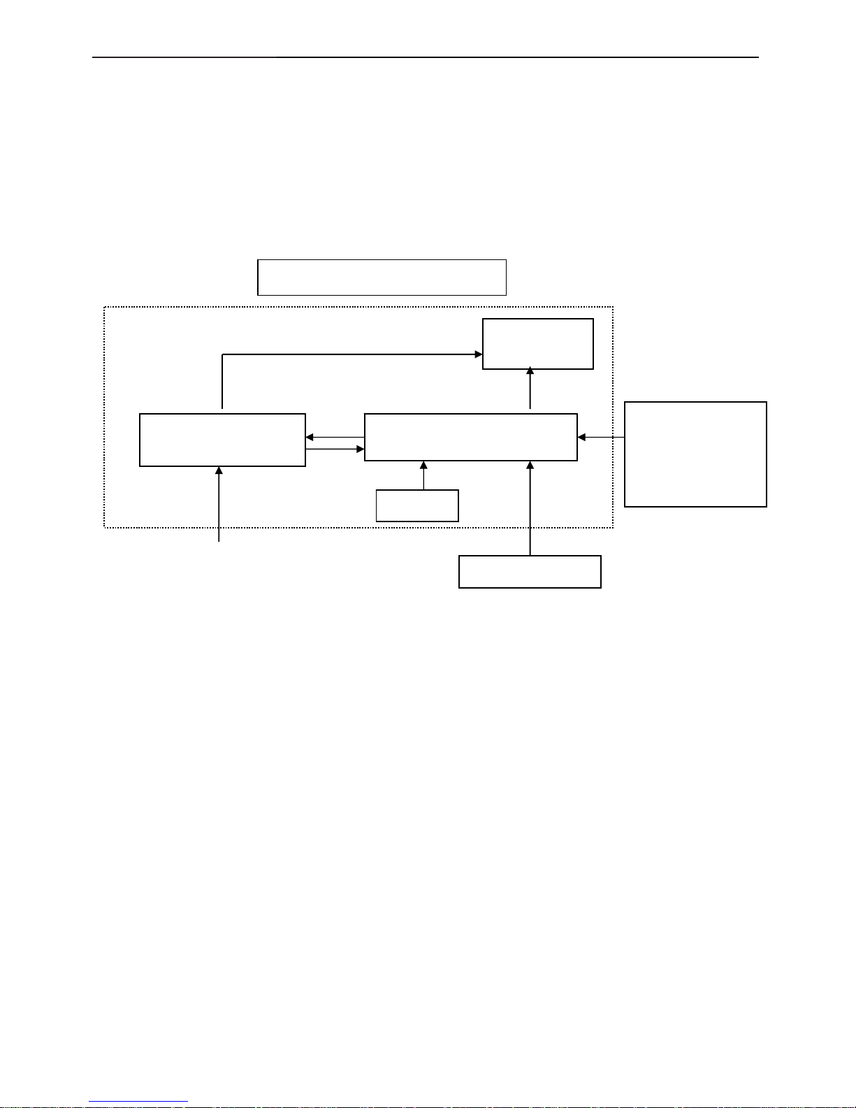
2. LCD Monitor Description
The LCD monitor will contain a main board, power board, key board, which house the flat panel control logic,
brightness control logic and DDC.
The power board will provide AC to DC Inverter voltage to drive the backlight of panel and the main board
chips each voltage.
Video signal, DDC
Power board
Flat Panel and
CCFL backlight
Main Board
Key board
RS232 Connector
For white balance
adjustment in factory
mode
CCFL Drive.
AC-IN
100-240V
Monitor Block Diagram
Host Computer
17" LCD Color Monitor Dell E157FPc
3. Operation instructions
3.1 General Instructions
Press the power button to turn the monitor on or off. The other control buttons are located at front panel of the
monitor. By changing these setting s, the picture can be adjusted to your personal preferences.
-
The power cord should be connected.
-
Connect the video cable from the monitor to the video card.
-
Press the power button to turn on the monitor, the power indicator will light up.
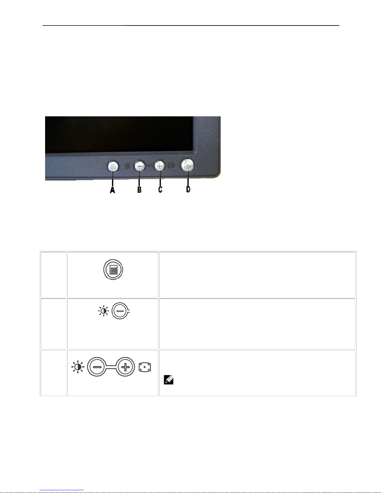
3.2 Control Buttons
A
MENU
The 'MENU' button is used to open the on-screen display (OSD), select
function icons, exit from menus and sub-menus, and to exit the OSD.
B
Brightness/Contrast Hot Key
Use this button for direct access to the 'Brightness' and 'Contrast' control
menu.
B C
-
And + buttons
Use these buttons to adjust (decrease/increase ranges) items in the OSD.
Note: you can activate automatic scroll feature by pressing
and holding either + or - button.
A
Menu button
B
Brightness / Contrast Hotkey and - button
C
Auto Adjust and + button
D
Power On/Off button with LED Indicator
15" LCD Color Monitor Dell E157FPc
7
C
Auto Adjust
Use this button to activate automatic setup and adjustment. The following
dialog will appear on screen as the monitor self-adjusts to the current
input:
Auto Adjust In Progress
Auto Adjustment button allows the monitor to self-adjust to the
incoming video signal. After using 'Auto Adjustment', you can further tune
your monitor by using the 'Pixel Clock' and 'Phase' controls in the OSD.
Note: Auto Adjust will not occur if you press the button while
there are no active video input signals, or attached cables.
D
Power Button & Indicator
The green LED indicates the monitor is on and fully functional. An amber
LED indicates DPMS power save mode.
The Power button turns the monitor on and off.
3.3 On Screen Menu/Display (OSD)
Direct-Access Functions
Function Adjustment Method
Auto adjustment
Use this button to activate automatic setup and adjustment. The
following dialog will appear on screen as the monitor self-adjusts
to the current input:
Auto Adjust In Progress
Auto Adjustment button allows the monitor to self-adjust to
the incoming video signal. After using 'Auto Adjustment', you
can further tune your monitor by using the 'Pixel Clock' and
'Phase' controls in the OSD.
Note: Auto Adjust will not occur if you press the button
while there are no active video input signals, or attached
cables.
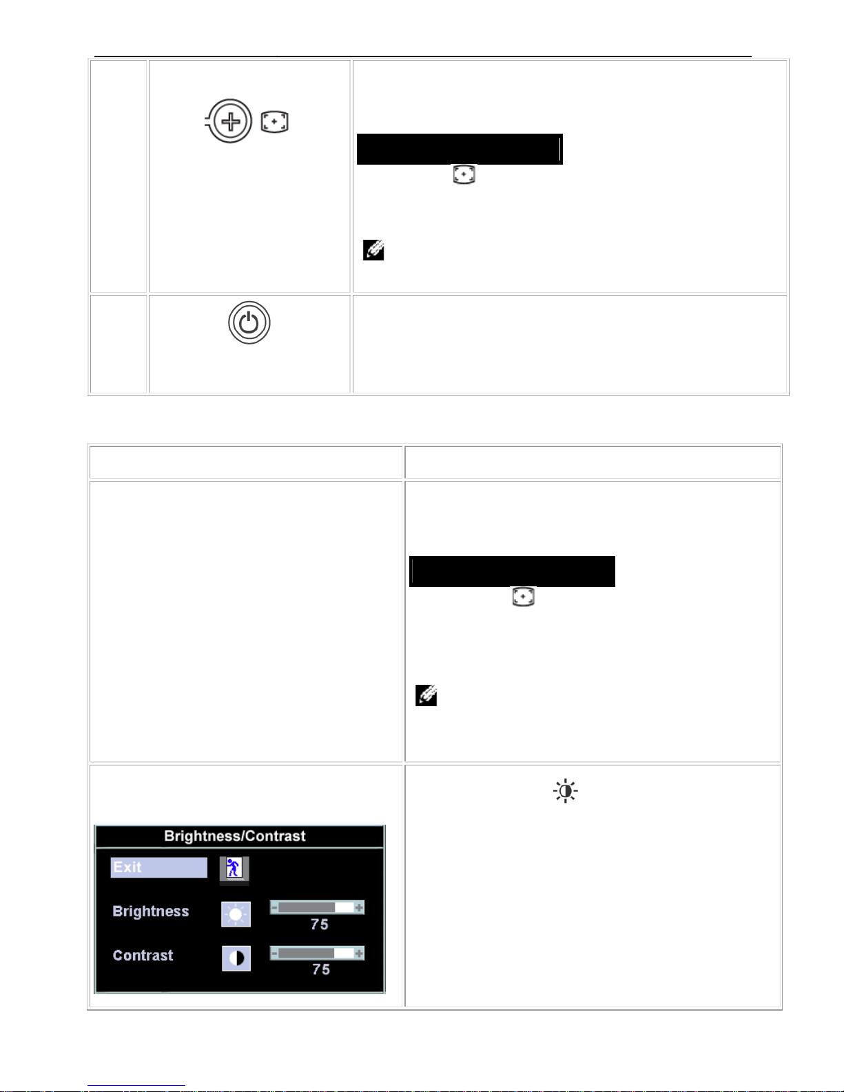
Brightness / Contrast
With the menu off, push
button to display the 'Brightness'
and 'Contrast' adjustment menu. The 'Brightness' function
adjusts the luminance of the flat panel. Adjust 'Brightness' first,
then adjust 'Contrast' only if further adjustment is necessary."+"
increase 'brightness'; " - "decrease 'brightness'
The 'Contrast' function adjusts the degree of difference between
darkness and lightness on the display screen.
"+" increase the 'contrast'
"-" decrease the 'contrast'

15" LCD Color Monitor Dell E157FPc
8
3.4 Adjusting the Picture
1. With the menu off, push the 'MENU' button to open the OSD system and display the main features menu.
A
Function icons
B
Main Menu
C
Menu icon
D
Sub-Menu name
E
Resolution
2. Push the - and + buttons to move between the function icons. As you move from one icon to another, the
function name is highlighted to reflect the function or group of functions (sub-menus) represented by that
icon. See the table below for a complete list of all the functions available for the monitor.
3. Push the 'MENU' button once to activate the highlighted function; Push -/+ to select the desired parameter,
push menu to enter the slide bar. Then use the - and + buttons, according to the i ndicators on t he menu, to
make your changes.
4. Push the 'Menu' button once to return to the main menu to select another function or push the 'Menu'
button two or three times to exit from the OSD.
15" LCD Color Monitor Dell E157FPc
9
Icon Menu Name
and sub-menus
Description
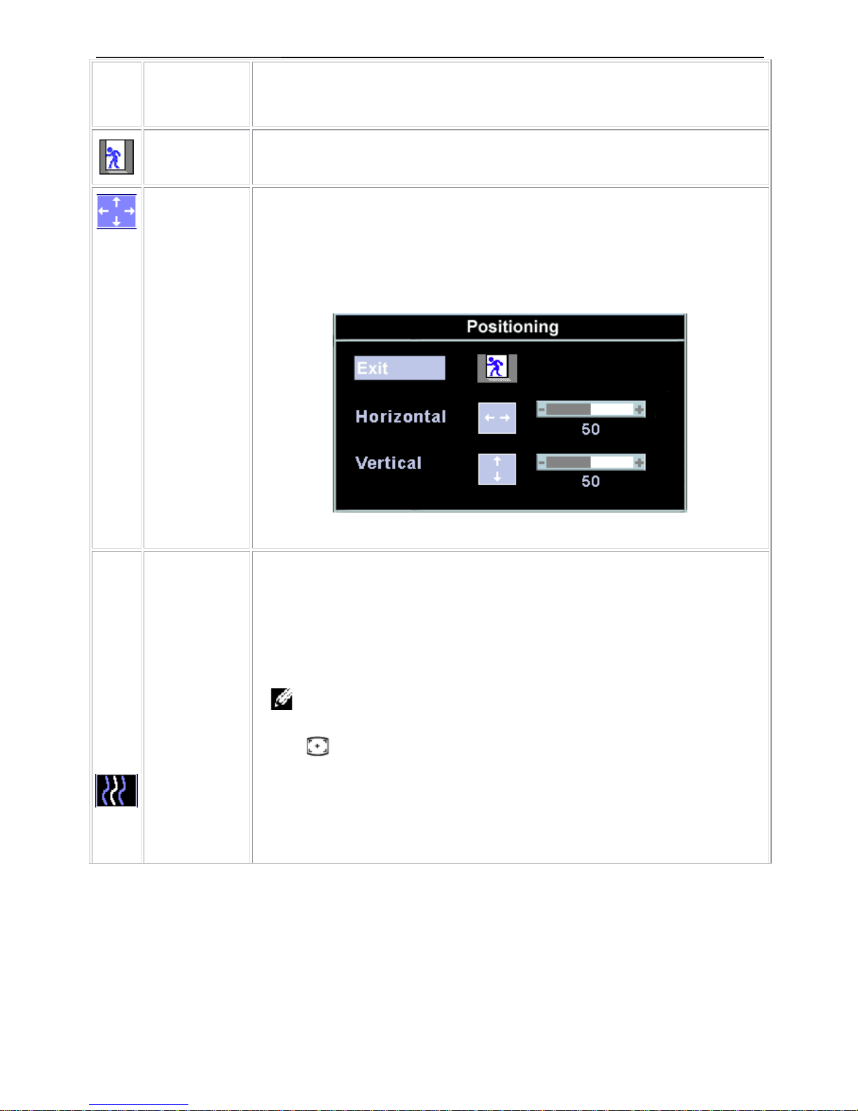
EXIT
This is used to exit out of the 'Main menu'.
Positioning:
Horizontal
Vertical
'Positioning' moves the viewing area around on the monitor screen.
When making changes to either the 'Horizontal' or 'Vertical' settings, no changes will
occur to the size of the viewing area; the image will simply be shifted in response to your
selection/change.
Minimum is '0' (-). Maximum is '100' (+).
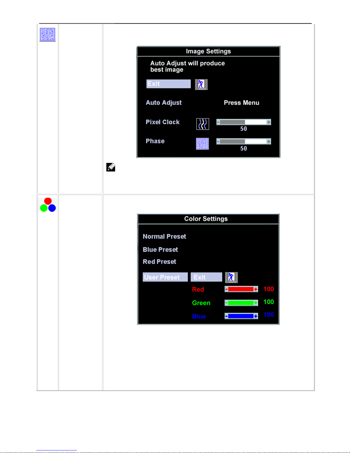
Image settings:
Auto Adjust
Even though your computer system can recognize your new flat panel monitor on
startup, the 'Auto Adjustment' function will optimize the display settings for use with your
particular setup.
Note: In most cases, 'Auto Adjust' will produce the best image for your
configuration; this function can be directly access via Auto Adjustment
hotkey.
Pixel Clock
The 'Phase' and 'Pixel Clock' adjustments allow you to more closely adjust your monitor
to your preference. These settings are accessed through the main OSD menu, by
selecting 'Image Settings'.
Use the - and + buttons to adjust away interference. Minimum: 0 ~ Maximum: 100
15" LCD Color Monitor Dell E157FPc
10
Phase
If satisfactory results are not obtained using the 'Phase' adjustment, use the 'Pixel Clock'
adjustment and then use 'Phase' again.
Note: This function may change the width of the display image. Use the
'Horizontal' function of the 'Position' menu to center the display image on the
screen.
Color Settings:
'Color Settings' adjusts the color temperature and saturation.
Normal Preset
'Normal Preset' is selected to obtain the default (factory) color settings.
Blue Preset
'Blue Preset' is selected to obtain a bluish tint. This color setting is typically used for text
based applications (Spreadsheets, Programming, Text Editors etc.).
Red Preset
'Red Preset' is selected to obtain a redder tint. This color setting is typically used for color
intensive applications (Photograph Image Editing, Multimedia, Movies etc.).
15" LCD Color Monitor Dell E157FPc
11
User Preset
'User Preset': Use the plus and minus buttons to increase or decrease each of the three
colors (R, G, B) independently, in single digit increments, from '0' to '100'.
Note: 'Color temperature' is a measure of the 'warmth' of the image colors
(red/green/blue). The two available presets ('Blu e' and 'Red') favor blue and red
accordingly. Select each one to see how each range suits your eye; or utilize the
'User Preset' option to customize the color settings to your exact choice.
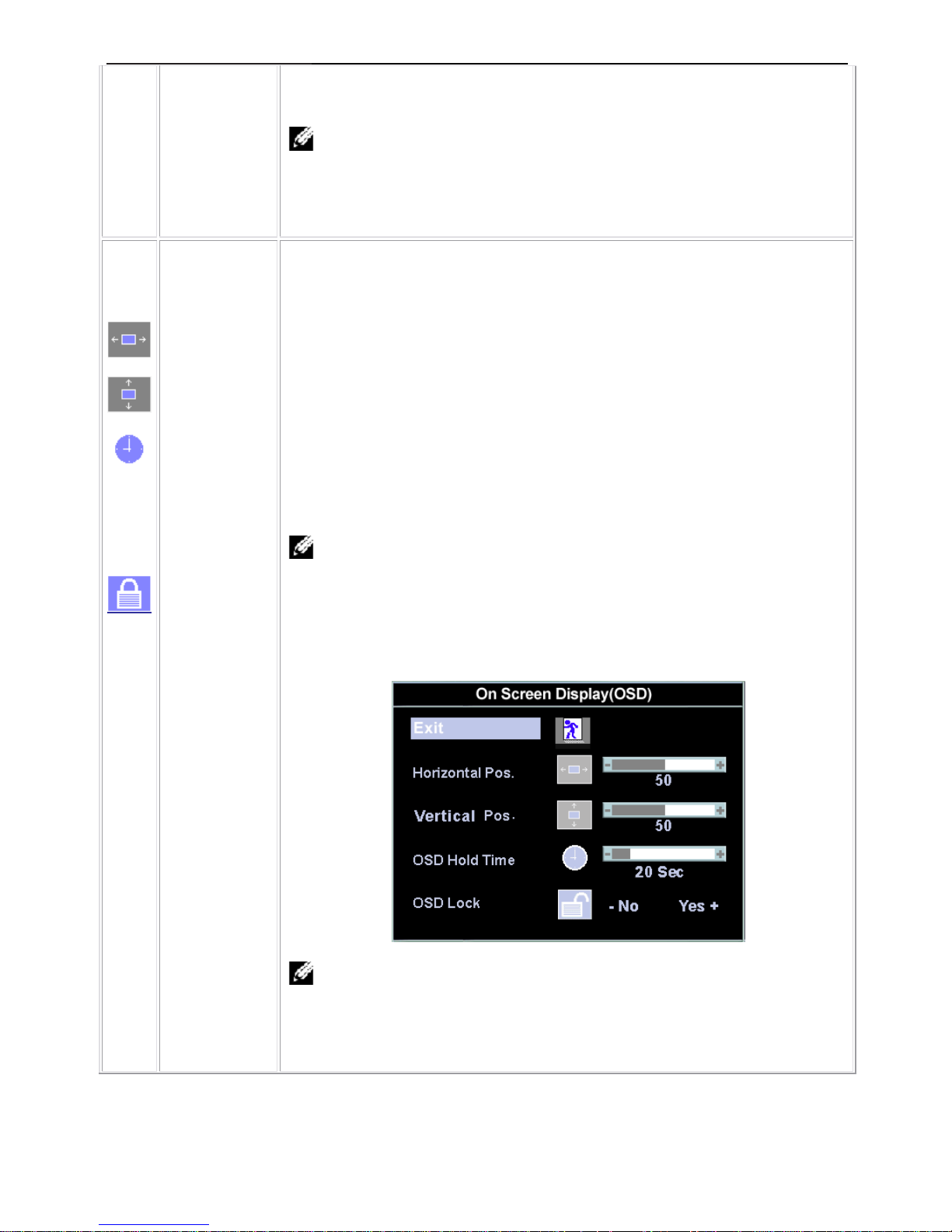
OSD Settings:
Each time the OSD opens, it displays in the same location on the screen. 'OSD Settings'
(horizontal/vertical) provides control over this location.
Horizontal
Position
- and + buttons move OSD to the left and right.
Vertical Position
- and + buttons move OSD down and up.
OSD Hold Time:
The OSD stays active for as long as it is in use.
'OSD Hold Time': Sets the length of time the OSD will remain active after the last time
you pressed a button.
Use the - and + buttons to adjust the slider in 5 second increments, from 5 to 60 seconds.
Note: Default 'OSD hold time' is 20 seconds.
OSD Lock
'OSD Lock': Controls user access to adjustments. When 'Yes' (+) is selected, no user
adjustments are allowed. All buttons are locked except the menu button.
All buttons can be locked or unlocked when the 'Menu' button is pushed and held for over
15 seconds.
Note: When the OSD is locked, pressing the 'Menu' button will take the user
directly to the 'OSD settings' menu, with 'OSD Lock' preselected on entry. Select
'No'(-) to unlock and allow user access to all applicable settings; or pressing the
'Menu' button for 15 seconds to unclock the OSD menu.
15" LCD Color Monitor Dell E157FPc
12
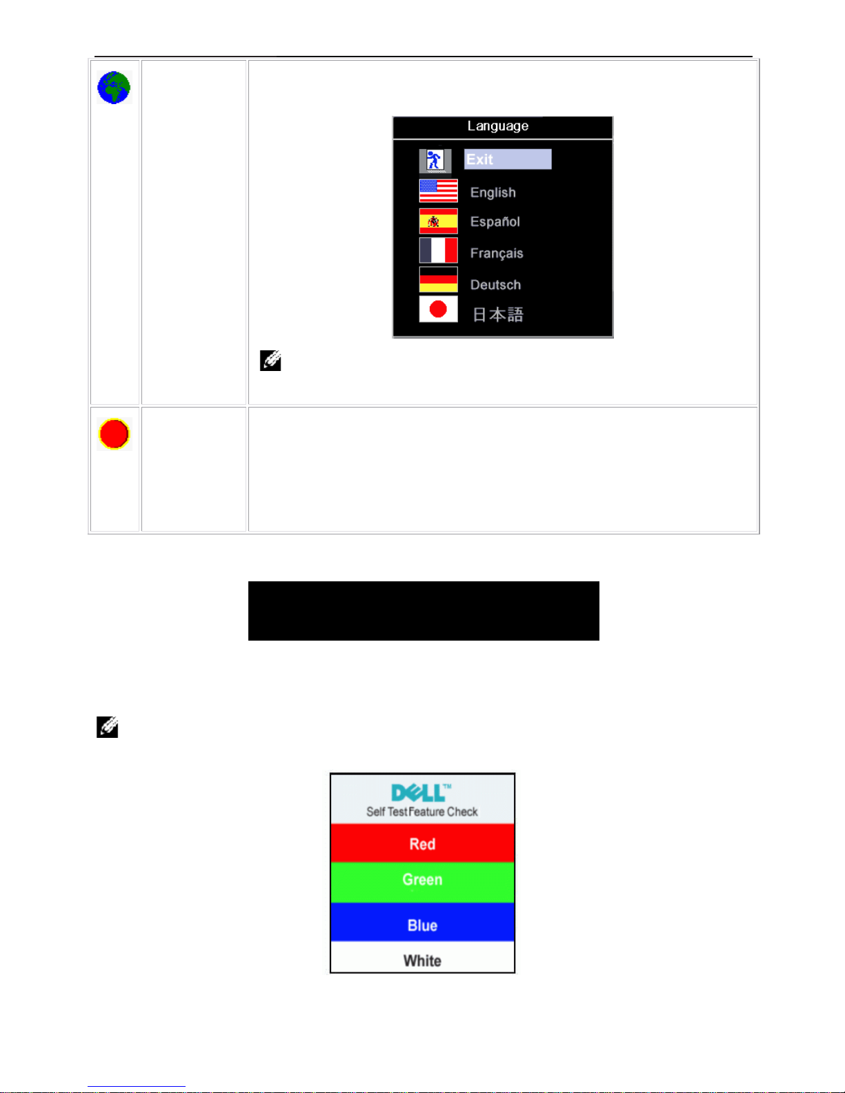
Language:
Language sets the OSD to display in one of five language s (English , Esp a ñol, Français,
Deutsch, Japanese).
Note: The language chosen affects only the language of the OSD. It has no
effect on any software running on the computer.
Factory Reset:
'Factory Reset' returns the settings to the factory preset values for the selected group of
functions.
‘Exit’ is used to exit out of 'Factory Reset' menu.
For 'All settings', all user adjustable settings are reset at one time except 'Language
settings'.
OSD Warning Messages
A warning message may appear on the screen indicating that the monitor is out of sync.
Cannot Display This Video Mode
Optimum resolution 1024X768 60 Hz
This means that the monitor cannot synchronize with the signal that it is receiving from the computer. Either the
signal is too high or too low for the monitor to use. See Specifications for the Horizontal and Vertical frequency
ranges addressable by this monitor. Recommen ded mode is 1024 X 768 @ 60Hz.
Note: The floating 'Dell - self-test Feature Check' dialog will appear on-screen if the monitor cannot sense a
video signal.
Occasionally , no warning messag e appears, but the screen is blank. This could al so indicate that the monitor is not
synchronizing with the computer. See Troubleshooting for more information.
15" LCD Color Monitor Dell E157FPc
13
4. Input/Output Specification
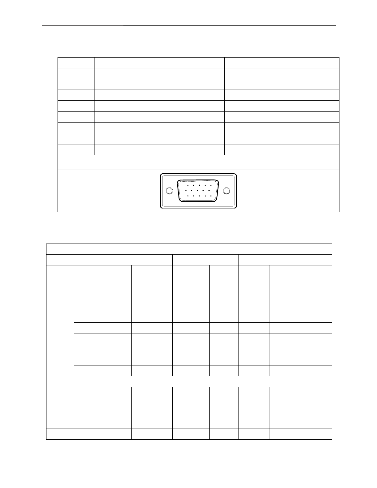
4.1 Input Signal Connector
Pin NO. Description Pin NO. Description
1. Red Video 9. +5V
2. Green Video 10. Logic Ground
3. Blue Video 11. RXD
4. TXD 12. DDC-Serial Data
5. Detector Pin 13. H-Sync
6. R-Ground 14. V-Sync
7. G-Ground 15. DDC-Serial Clock
8. B-Ground
VGA Connect or layout
15
6
10
11 15
4.2 Factory Preset Display Modes
VESA MODES
Horizontal Vertical
Mode Resolution Total
Nominal
Frequency
+/- 0.5kHz
Sync
Polarity
Nominal
Freq.
+/- 1 Hz
Sync
Polarity
Nominal
Pixel
Clock
(MHz)
640x480@60Hz 800 x 525 31.469 N 59.940 N 25.175
640x480@75Hz 840 x 500 37.500 N 75.00 N 31.500
800x600@60Hz 1056 x 628 37.879 P 60.317 P 40.000
VGA
800x600@75Hz 1056x625 46.875 P 75.000 P 49.500
1024x768@60Hz 1344x806 48.363 N 60.004 N 65.000
XGA
1024x768@75Hz 1312x800 60.023 P 75.029 P 78.750
IBM MODES
Mode Resolution Total
Nominal
Frequency
+/- 0.5kHz
Sync
Polarity
Nominal
Freq.
+/- 1 Hz
Sync
Polarity
Nominal
Pixel
Clock
(MHz)
DOS 720x400@70Hz 900 x 449 31.469 N 70.087 P 28.322
15" LCD Color Monitor Dell E157FPc
14
4.3 Power Supply Requirements
A/C Line voltage range 100 V ~ 240 V± 10 %
A/C Line frequency range 50 ± 3Hz, 60 ± 3Hz
Input Volt age transients 280 volts AC for 10 sec @40℃
Current 0.6A max, at 100V, 0.35A max, at 240 V
Peak surge current
< 60A peak at 240 VAC and cold starting
< 30A peak at 120VAC and cold starting
Leakage current < 3.5mA
Power line surge
No advance effects (no loss of information or defect)
with a maximum of 1 half-wave missing per second
15" LCD Color Monitor Dell E157FPc
15
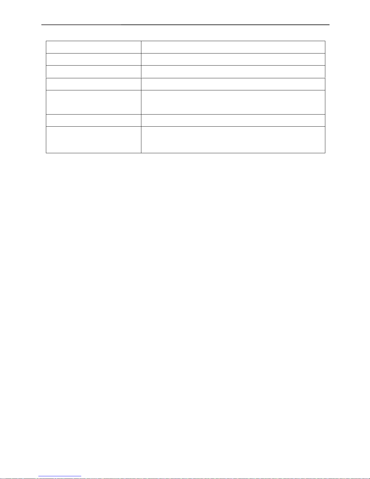
4.4 Panel Specification
4.4.1 Display Characteristics (For LTM150XO-L01 panel)
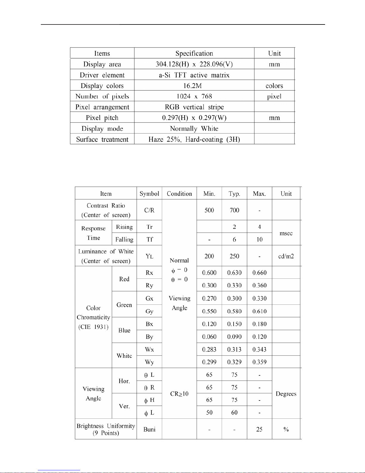
4.4.2 Optical Characteristics (For LTM150XO-L01 panel)
Measured conditions as follows: Ta=25±2°C, VDD=3.3V,fv=60Hz,f
Dclk
=65MHz,Llamp=8mA.
15" LCD Color Monitor Dell E157FPc
16
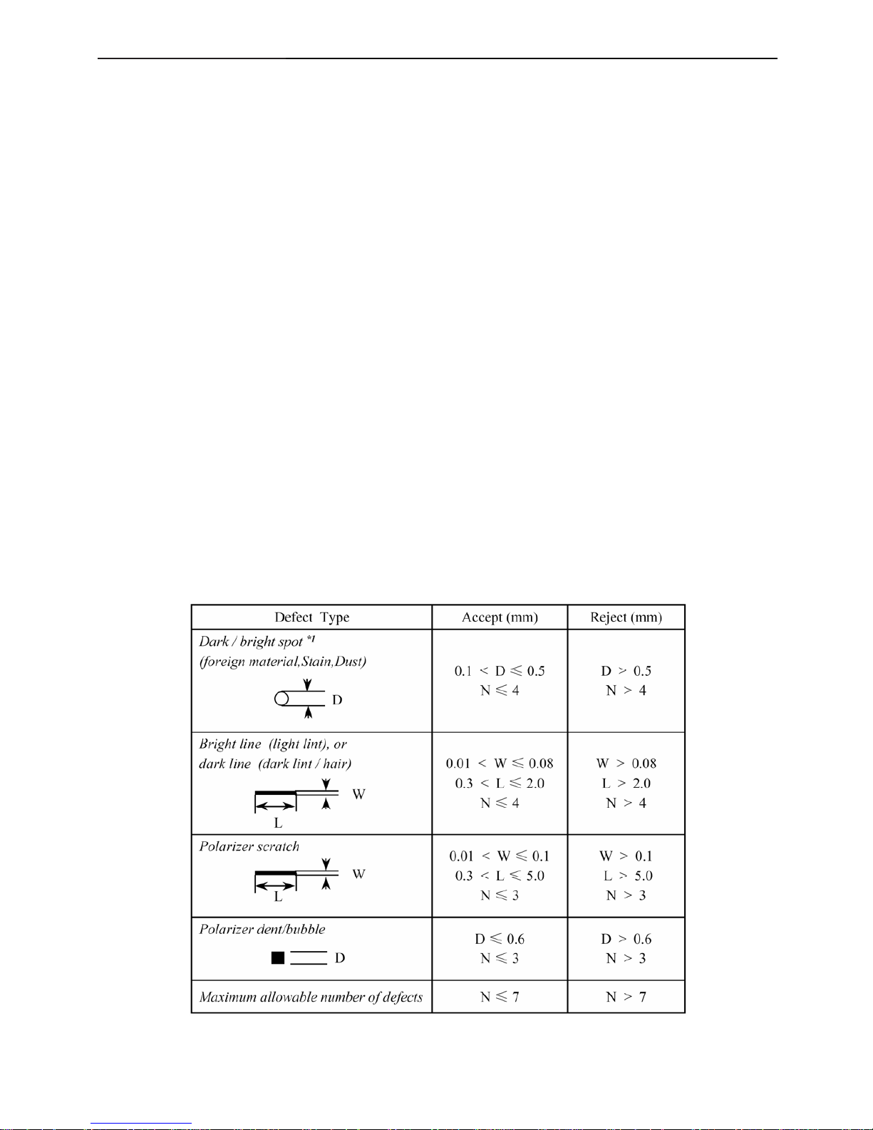
4.5 Definition of Pixel Defects
For LTM150XO-L01 panel
4.5.1 Defect Modes
Dark / bright spots
Points on the display which appear dark / bright and remain unchanged in size
Dark / bright lines
Lines on the display which appear dark / bright and remain unchanged in size
Polarizer scratch
When the unit is lit a light, line is seen across a darker background; line does not vary in size
Polarizer dent
When the unit is lit a light, light(white) spots appear against a darker background, and do not vary in size
Bright/dark dot
A sub-pixel (R, G, B dot) stuck off / on
4.5.2 Mechanical Inspection
Chassis Gap max. 0.7mm
Light Leakage there shall be no visible light around the edges of the screen.
* If there is none identified criteria in this specification, Samsung will refer productionspecification that
Customer and Samsung agreed.
* If there is mechanical dimension issue which has no designated tolerance, Samsung will apply natural
tolerance.
[ D : diameter, W : width, L : length, N : count ]
*1 : Translucent edge is ignored in measuring the diameter of spot.
15" LCD Color Monitor Dell E157FPc
17
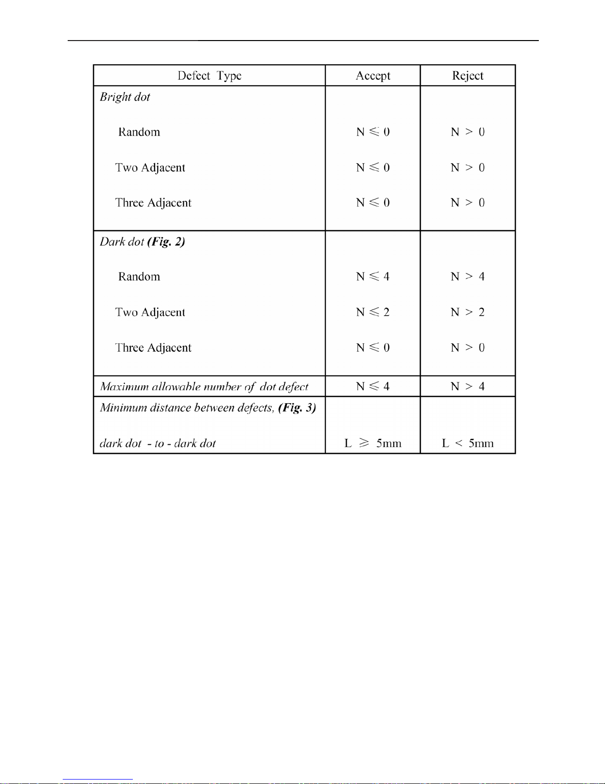
4.5.3 Electrical Inspection
[L: length, N: count]
Definitions/ Notes;
- A bright dot any Red, Green, or Blue pixel suck in the “On” mode.
- A dark dot any Red, Green, or Blue pixel suck in the “Off ” mode.
- Inspection pattern for electrical defect should be pure R, G, B, Black and White.
- Adjacent two dots in horizontal direction will be considered as one dot.
15" LCD Color Monitor Dell E157FPc
18
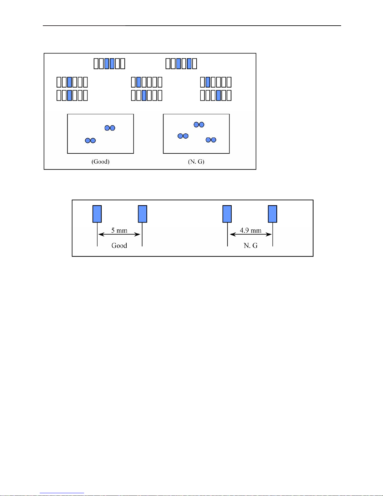
Fig. 2. Dark dot defect description
【two adjacent】
Fig. 3. Minimum distance between dot defects
【dark dot - to - dark dot】
* Minimum distance criteria is applied to the defect , which are not defined as adjacent dot(two or three) in the spec.
* Will not considered the distance between bright dot & dark dot.
* Will not considered the distance between dot & mechanical defect.
* A dot which is over the half (50%) of a dot size will be considered as one bright dot.
15" LCD Color Monitor Dell E157FPc
19
5. Block Diagram
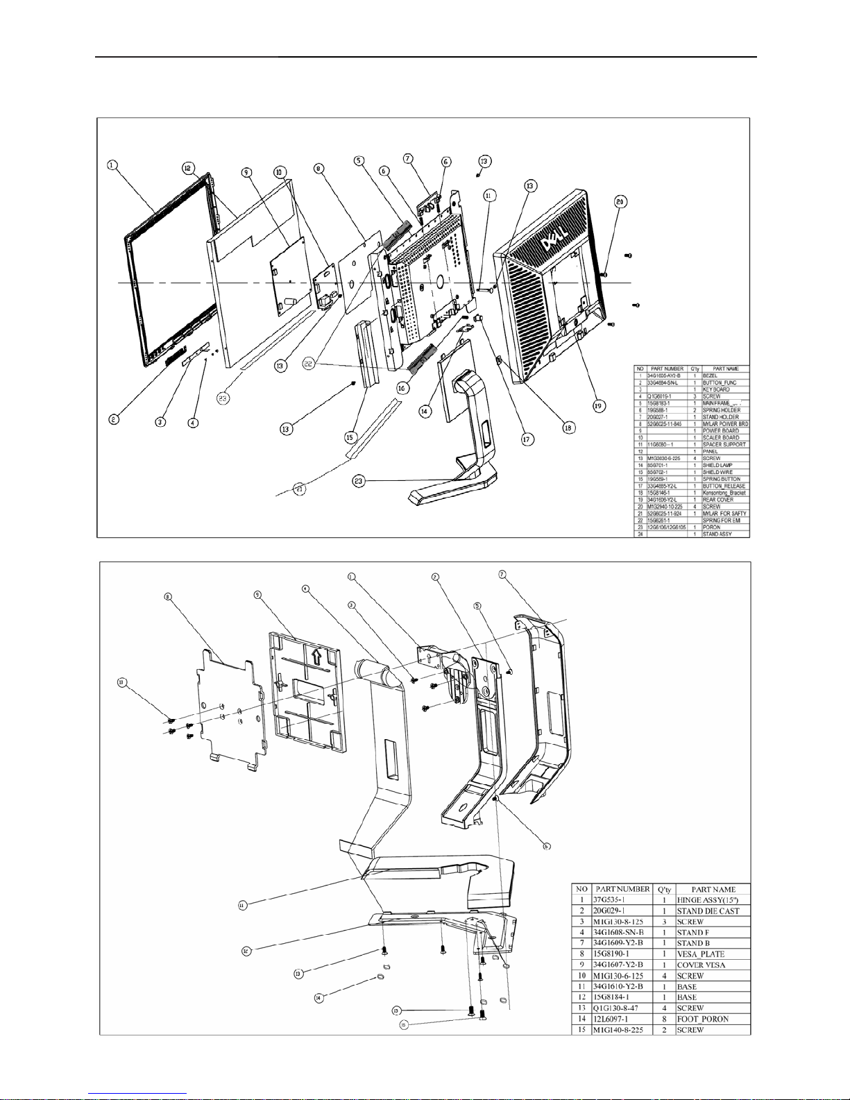
5.1 Monitor Exploded View
15" LCD Color Monitor Dell E157FPc
20
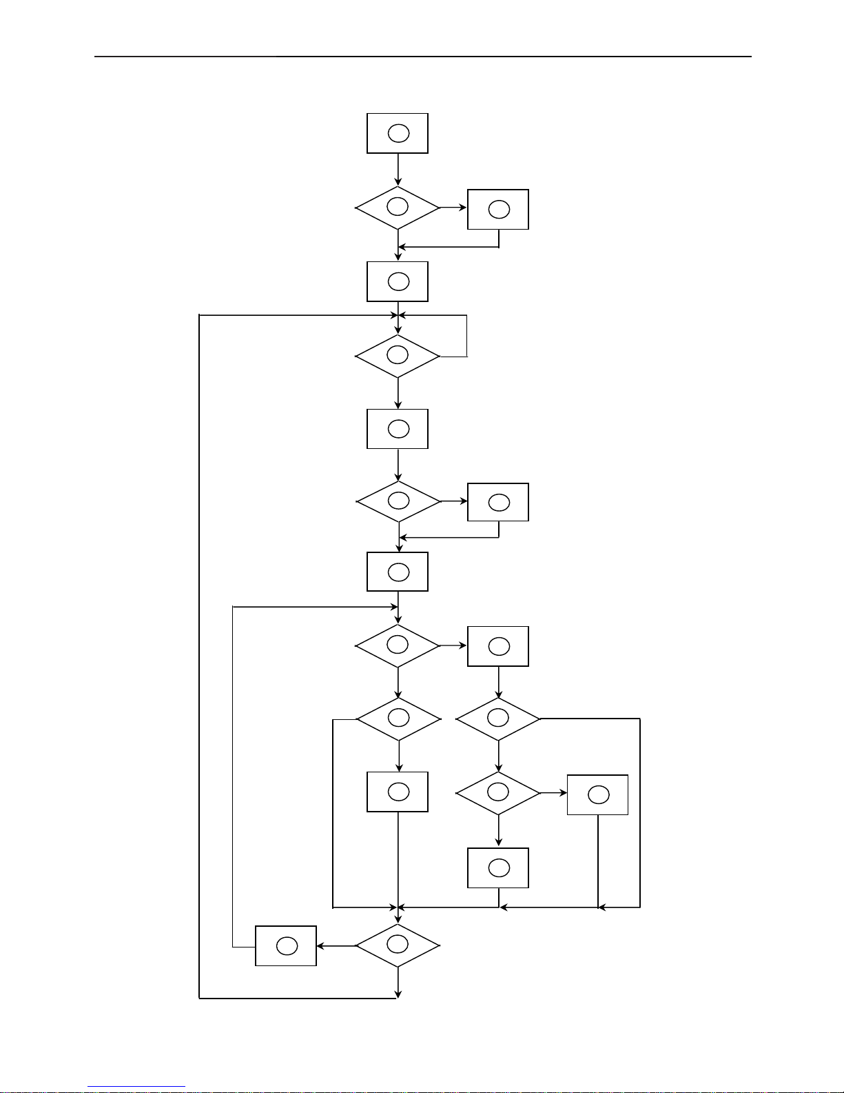
5.2 Software Flow Chart
1
2
N
Y
5
Y
N
10
Y
N
12
Y
N
7
Y
N
6
4
3
8
9
14
11
13
Y
N
15
Y
N
16
17
19
Y
N
18

15" LCD Color Monitor Dell E157FPc
21
1) MCU Initializes.
2) Is the EEprom blank?
3) Program the EEprom by default values.
4) Get the PWM value of brightness from EEprom.
5) Is the power key pressed?
6) Clear all global flags.
7) Are the AUTO and SELECT keys pressed?
8) Enter factory mode.
9) Save the power key status into EEprom. Turn on the LED and set it to green color. Scalar initializes.
10) In standby mode?
11) Update the lifetime of back light.
12) Check the analog port, are there any signals coming?
13) Does the scalar send out an interrupt request?
14) Wake up the scalar.
15) Are there any signals coming from analog port?
16) Display "No connection Check Signal Cable" message. And go into standby mode after the message
disappears.
17) Program the scalar to be able to show the coming mode.
18) Process the OSD display.
19) Read the keyboard. Is the power key pressed?
15" LCD Color Monitor Dell E157FPc
22
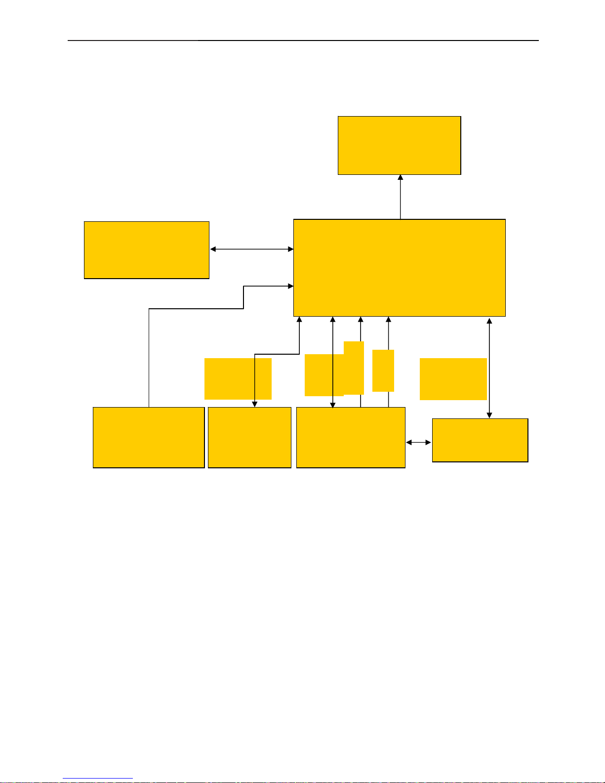
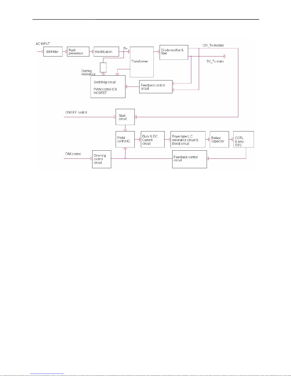
5.3 Electrical Block Diagram
5.3.1 Main Board
OSD Control Interface
(CN403)
Scalar GM2621
(Include MCU, ADC, OSD)
(U401)
Flash Memory
SST25VF020-20- 4C-SAE
(U402)
EEPROM
M24C16-MN6T
(U403)
D-Sub
Connector
(CN405)
EEPROM (U404)
M24C02WMN6
R
G
B
RXD
TXD
DB15_SDA,
DB15_SCL
EPR_SDA
EPR_SCL
LCD Interface
(CN101)
H
V
15" LCD Color Monitor Dell E157FPc
23
5.3.2 Inverter/Power Board
15" LCD Color Monitor Dell E157FPc
24
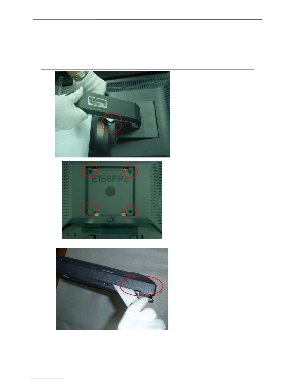
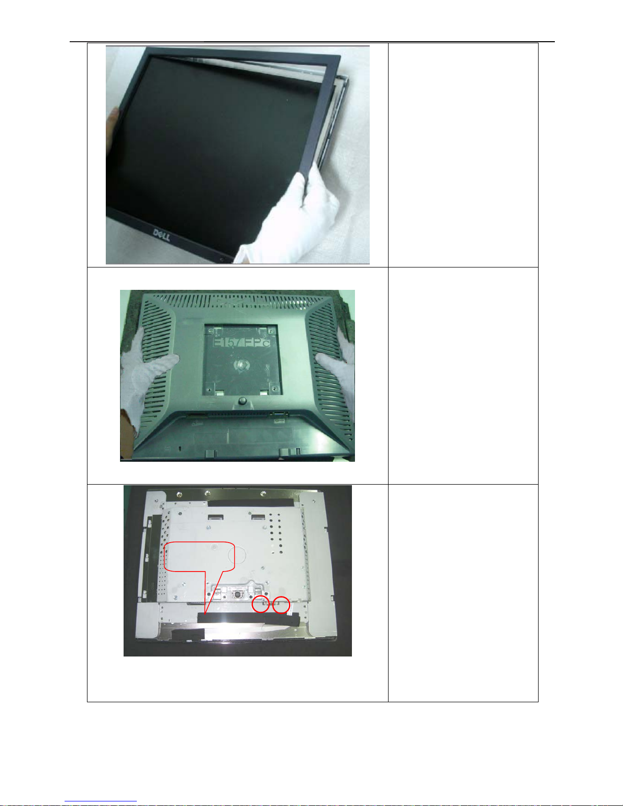
6. Mechanical Instruction
Tools: 2 Power screwdrivers (φ=5mm,L=60mm); 1 small cross screwdriver; turnbuckle driver;
Setting: Power screwdriver torque A=11 kgF. Cm; torque B=6 kgF. Cm
Note: Firstly, put the monitor on a soft, flat and clean surface, wear gloves.
Fig Remark
Remove stand:
Press the Stand release button
and lift up the Stand and away
from the monitor.
Remove bezel:
1. Remove the 4 screws by
torque A
2. Pry the monitor up then find
out the hooks’ position, use
the tool (like the picture or
other card) to insert into the
gap of bezel and rear cover.
15" LCD Color Monitor Dell E157FPc
25
3. Take off the bezel
Remove rear cover :
Turn over the monitor as the Fig,
hold the rear cover
, then slightly remove it.
Remove the two screws by
Torque B.
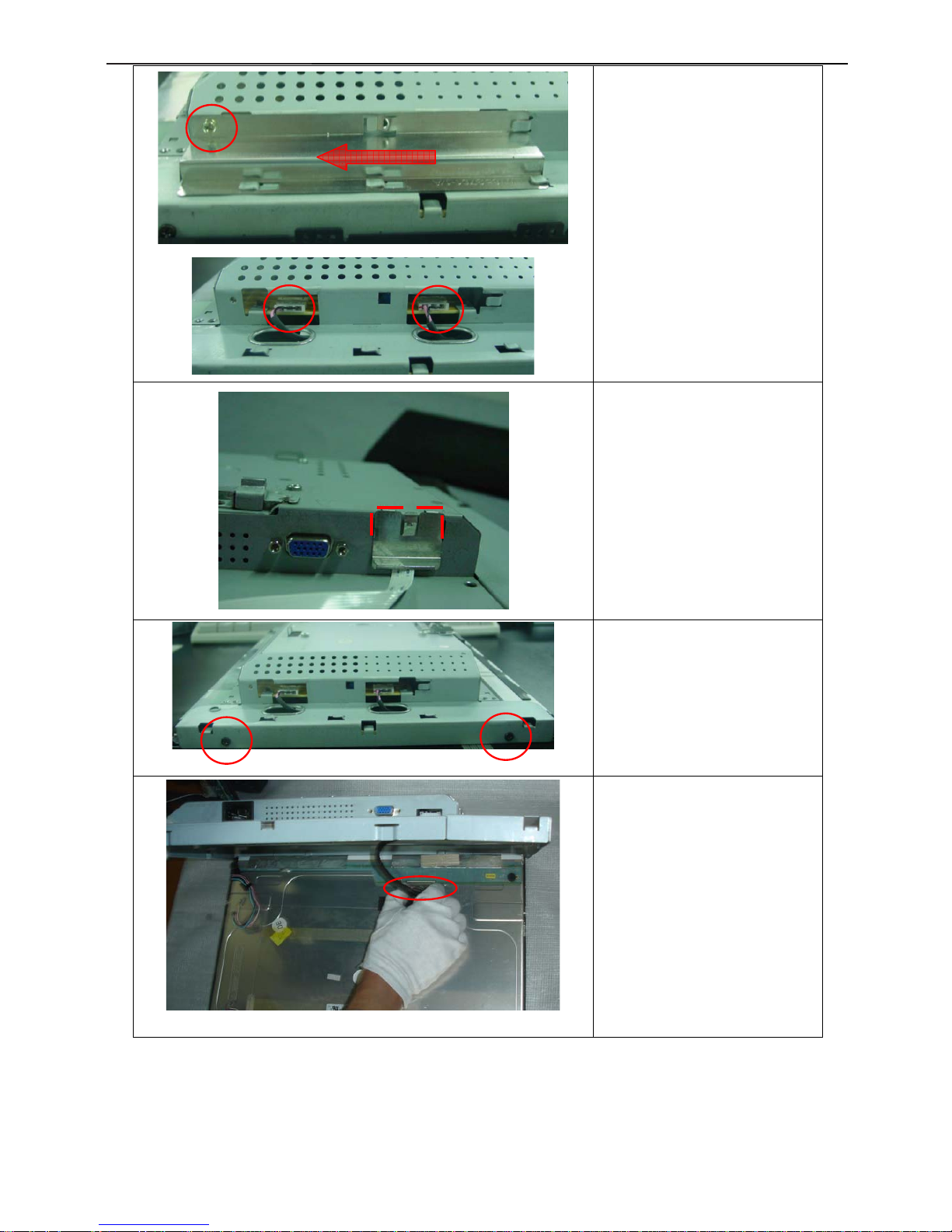
Install:
Fix the keyboard cable by black
tape as the figure showed.
Black tape
15" LCD Color Monitor Dell E157FPc
26
Remove the shield :
1. Remove the screw by Torque
B or by manual and remove the
shield ,then remove the back
light connector
Remove the connector
Remove the two screws by
manual or torque = 3kgF.Cm and
remove the main frame
Remove the main frame and at
the same time disconnect the
L VDS connector
15" LCD Color Monitor Dell E157FPc
27
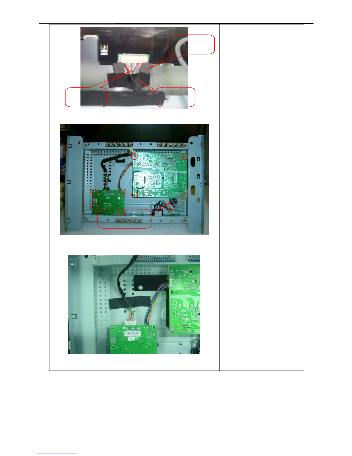
Install:
Fix the L VDS connector by black
tape and EVA washers.
Remove the nine screws by
Torque B and remove the power
board and main board.
Note: Magnetism ring should be
laid at the right of power board
Fix the L V DS cabl e by bla ck tape
as the figure.
Magnetism ring
Black tape
LVD S Cable
EVA washers

15" LCD Color Monitor Dell E157FPc
28
Screw AC ground line as the
figure.
Note: The green line can’t be
pressed under the power board.
Note: The pins can’t gore the
blue and purple lines.
The end
ground

15" LCD Color Monitor Dell E157FPc
29
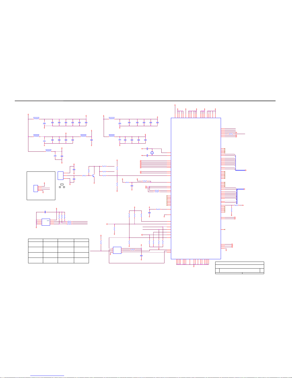
7. Schematic Diagram
7.1 Main Board
DDC_SCL_VGA
(3)
BLUE- (3)
R448
2.2K 1/16W
GND
R434
75 1/16W
GND
DDC_SDA_VGA
(3)
R435
75 1/16W
C436
0.047uF
+5V
DDC_SDA_A
C443
NC
R441
100 1/16W
R439
75 1/16W
(10 mil,
┰キ︽絬
)
CN405
DB15
1
6
2
7
3
8
4
9
5
11
12
13
14
15
10
1716
R444
10K 1/16W
(8 mil)
R450
4.7K 1/16W
+5V
GREEN+(3)
GND
Pins 6/7/8 are R/G/B
return lines resp.
U404
M24C02WMN6
4
81
2
3
7
6
5
GND
VCCA0
A1A2WP
SCL
SDA
C432
0.047uF
R436
75 1/16W
R453
220 1/16W
GND
GND
R446 220 1/16W
D404
BAV99
3
1
2
+3.3V_VDD
BLUE+ (3)
FB410
60 OHM
1 2
D
Input Connectors
A
26Wednesday, June 29, 2005
Title
Size Document Number Rev
Date: Sheet
of
HS_in
D403
BAV99
3
1
2
C442
NC
R449
2.2K 1/16W
R440
75 1/16W
GND
HS (3)
R443
100 1/16W
FB411
60 OHM
1 2 C433
0.047uF
D407
BAT54C
3
1
2
RED+ (3)
C448
NC
R452
4.7K 1/16W
GND
R447 220 1/16W
R438
75 1/16W
EDID_WP
(3)
C439
0.1uF/16V
GND
R442
100 1/16W
RED- (3)
Gin
GND
GND
C444
0.1uF/16V
EDID_WP
FB412
60 OHM
1 2
D408
LL5232B 5.6V 5%
SPI_3V3
D411
LL5232B 5.6V 5%
R451
4.7K 1/16W
CABLE_DET (3)
D409
LL5232B 5.6V 5%
Bin
GREEN- (3)
C434
0.047uF
VGA_5V
C437
0.047uF
C438
0.047uF
SPI_3V3
R445
220 1/16W
R454
220 1/16W
D402
NC
3
2
1
D405
BAV99
3
1
2
VGA_PLUG
75-ohm terminating resistor
very close to the VGA
conn.
VS (3)
GND
VS_IN
VGA_5V
+3.3V_VDD
Rin
D412
LL5232B 5.6V 5%
+5V
C447
NC
D410
LL5232B 5.6V 5%
D406
LL5232B 5.6V 5%
R455
220 1/16W
15" LCD Color Monitor Dell E157FPc
30
GND
LVDS_E4
D
gm2621
Custom
36Wednesday, June 29, 2005
Title
Size Document Number Rev
Date: Sheet
of
GND
LVDS_O[0..9] (5)
1.8V_DVDD
NVRAM_SDA
UDART_DI
R422
10K 1/16W
R400 NC
X401
14.318MHz
(PWM0)
UART on GPO
LVDS_E[0..9]
Standard SPI ROM
RED-(2)
LVDS_O3
LVDS_E9
R404NC
1.8V_AVDD
PBIAS (6)
C403
0.1uF/16V
GND
3.3V_LAVDD
LVDS_O6
LVDS_E5
C431
0.1uF/16V
R426
4.7K 1/16W
3.3V_VD
D
Boot-Strap Configuration:
SPI_3V3
LVDS_O4
GND
3.3V_AVDD
LVDS_E7
R430
NC
R431 NC
U403
M24C16-MN6T
1
2
3
4 5
6
7
8
A0
A1
A2
VSS SDA
SCL
WC
VCC
GND
GREEN+(2)
VS(2)
GND
LVDS_O9
3
GPO_0
LBADC1 (4)
R407
4.7K 1/16W
C430
0.1uF/16V
LVDS_E[0..9] (5)
LED_O (4)
R432
4.7K 1/16W
C440
NC
3.3V_PVDD
+3.3V_VDD
R423
4.7K 1/16W
R403NC
LVDS_O7
DDC_SDA_VGA(2)
LVDS_O2
R418
NC
R410 100 1/16W
GND
R401 NC
LBADC2 (4)
R425
4.7K 1/16W
R417
4.7K 1/16W
Default
C402
0.1uF/16V
Open
+3.3V_VDD
HOLD#
C441
0.1uF/16V
+
C409
22uF/16V
/WP
ROM_WP#
3.3V_PVDD
10 KOhm
R406
4.7K 1/16W
3.3V_PVDD
PPWR (6)
C405
0.1uF/16V
GND
R437
NC
UART on DDC
+5V
OPTIONAL
FOR
DEBUGGING
PURPOSES
ONLY
GND
LVDS_O5
R408
4.7K 1/16W
FB406
120OHM
C411
0.1uF/16V
GND
PPWR
Q402
NC
32
1
C446
0.1uF/16V
Ext. ROM JTAG Off
LED_G (4)
CABLE_DET (2)
C435
0.1uF/16V
3.3V_AVDD
R428
NC
GND
C423
0.1uF/16V
GND
3.3V_DVDD
DDC_SCL_VGA(2)
EDID_WP
(2)
C414
0.1uF/16V
R427
4.7K 1/16W
ATMEL_EN
GND
HS(2)
C418
0.1uF/16V
Name
LVDS_O[0..9]
C420
0.1uF/16V
C426
0.1uF/16V
C406
0.1uF/16V
3.3V_AVDD
UDART_DI
POWER_ON (4)
NVRAM_SDA
R421
5.6K 1/16W
U405
NC
1
2
3
GND
RSTN
VCC
GND
LVDS_O0
C421
0.1uF/16V
(SPI_CSn)
ROM_SCLK
R416
4.7K 1/16W
C413
0.1uF/16V
PBIAS
LVDS_E0
R409 100 1/16W
FB404
120OHM
Standard SPI ROM
LVDS_E3
GND
GND
U401
gm2621
MQFP-128
56
49
50
33
34
36
37
38
39
35
29
40
62
60
27
45
41
96
42
119
100
61
12
10
9
8
5
4
3
24
6
7
94
93
52
127
125
124
123
46
44
43
51
28
32
31
30
13
14
15
16
85
19
20
21
22
11
23
99
59
97
103
104
105
106
108
109
110
111
89
90
65
64
121
120
122
126
128
57
58
63
66
67
69
72
73
75
76
80
81
83
84
107
112
113
114
115
12648
1755118
87
9598102
91
116
53
10192827422547
687177
79
867870
185488
117
GPO_1
PBIAS
PWM0 / GP0_4
O_CLK_N
O_CLK_P
O_CH2_P
O_CH1_N
O_CH1_P
O_CH0_N
O_CH2_N
RESERVED
O_CH0_P
SPI_DO
SPI_CLK
RESERVED
RESERVED
O_BON
GREEN+
RESERVED
PWM1 / GPO_5
RED-
SPI_DI
E_CH2_P
E_CLK_P
E_CLK_N
E_CH3_P
RESERVED
RESERVED
RESERVED
RESERVED
RESERVED
E_CH3_N
BLUE-
BLUE+
CRVSS
PPWR
GPIO_13
GPIO_12
GPIO_11
RESERVED
RESERVED
RESERVED
GPO_0
RESERVED
O_CH3_P
O_CH3_N
RESERVED
E_CH1_N
E_CH1_P
E_CH0_N
E_CH0_P
AVSS_DVI
RESERVED
RESERVED
RESERVED
RESERVED
E_CH2_N
RESERVED
RED+
SPI_CSn
GREEN-
AVSS_ADC
AVDD_ADC_18
VBUFC_RPLL
VDD_RPLL_18
XTAL
TCLK
AVDD_RPLL_33
RESETn
HSYNC
VSYNC
DDC_SDA_VGA
DDC_SCL_VGA
GPIO_9
GPIO_8
GPIO_10
GPIO_14
AVDD_BIAS_33
GPO_2
GPO_3
RESERVED
DDC_SCL_DVI
DDC_SDA_DVI
REXT
RX2+
RX2RX1+
RX1RX0+
RX0RXC+
RXC-
VSS_RPLL
LBADC_VSS
LBADC_IN3
LBADC_IN2
LBADC_IN1
AVSS_BIAS
VSS_OUT
VSS_OUT
CVDD_18
CVDD_18
CVDD_18
CVDD_18
AVSS_ADC
AVSS_ADC
AVSS_ADC
RVDD_33
LBADC_VDD_33
RVDD_33
AVDD_ADC_33
AVDD_ADC_33
AVDD_DVI_33
AVDD_DVI_33
VDD_OUT_33
VDD_OUT_33
VDD_OUT_33
AVSS_DVI
AVSS_DVI
AVSS_DVI
AVSS_DVI
AVDD_DVI_18
AVDD_DVI_18
AVDD_DVI_18
CRVSS
CRVSS
CRVSS
CRVSS
C404
0.1uF/16V
UART_PIN_SEL
U402
SST25VF020-20-4C-SAE
1
2
3
4
8
7
6
5
CE#
SO
WP#
VSS
VDD
HOLD#
SCK
SI
GND
3.3V_DVDD
+3.3V_VDD
R424
4.7K 1/16W
+
C419
22uF/16V
3.3V_PVDD
RESETn
FB401
120OHM
LVDS_E6
Open
R476
NC
+5V
BLUE+(2)
C412
0.1uF/16V
GND
R411 100 1/16W
Close to respective power Pins
1.8V_DVDD
GND
NVRAM_SCL
LVDS_O1
ROM_WP#
EDID_WP
LVDS_E8
3.3V_LAVDD
Open
3.3V_DVDD
+1.8V_VDD
BLUE-(2)
LVDS_E1
CN402
1
2
3
4
GND
FB402
120OHM
R419
0 1/16W
NVRAM_SCL
C428 33pF
ATMELSPI ROM
+3.3V_VDD
UDART_DO
R456
NC
R477
4.7K 1/16W
C445
0.1uF/16V
2
(PWM1)
+3.3V_VDD
C417
0.1uF/16V
R429
10K 1/16W
FB403
120OHM
+
C425
22uF/16V
C424
0.1uF/16V
R433
NC
GREEN-(2)
C427 33pF
GND
ROM_SDI
Close to respective power Pins
/WP
ATMELSPI ROM
C422
0.1uF/16V
UDART_DO
FB405
120OHM
C410
0.1uF/16V
Close to respective power Pins
GND
RED+(2)
LVDS_E2
ROM_WP#
BRIGHTNESS(6)
+
C416
22uF/16V
1
+
C401
22uF/16V
GND
C429
NC
Open
1.8V_AVDD
+5V
G-PROBE
LVDS_O8
HOLD#
C407
0.1uF/16V
R402 249 1/16W
V_EDID_ATMEL
 Loading...