

Dell E153FPTc Service Manual
1
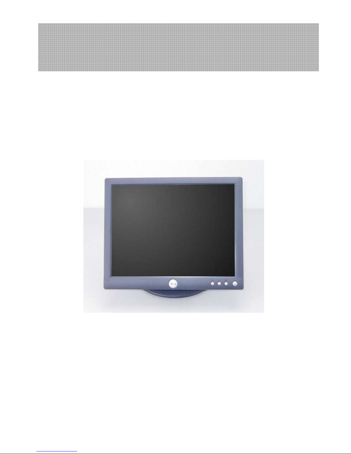
15” LCD MONITOR
DELL E153FPTc
THESE DOCUMENTS ARE FOR REPAIR SERVICE INFORMATION ONLY.EVER Y REASONABLE EFFOR T HAS
BEEN MADE TO ENSURE THE ACCURACY OF THIS MANUAL; WE CANNOT GUARANTEE THE ACCURACY
OFTHIS INFORMATION AFTER THE DATE OF PUBLICATION AND DISCLAIMS RELIABILITY FOR CHANGES,
ERRORS OR OMISSIONS.
Service Manual

2
Table of Contents
Table of Contents ------------------------------------------------------------------------------------------------------------------ 02
Revision List -----------------------------------------------------------------------------------------------------------------------03
1. Monitor Specification ---------------------------------------------------------------------------------------------------------04
2. LCD Monitor Description -----------------------------------------------------------------------------------------------------05
3. Operation Instructions ------------------------------------------------------------------------------------------------------06
3.1 General Instructions ----------------------------------------------------------------------------------------------------06
3.2 Control Button ----------------------------------------------------------------------------------------------------------------06
3.3 Adjusting The Picture -----------------------------------------------------------------------------------------------------07
4. Input/Output Specification ----------------------------------- -------------------------------------- -----------------------12 -16
4.1 Input Signal Connector ----------------------------------------------------------------------------------------------------12
4.2 Factory Preset Display Modes -------------------------------------------------------------------------------------------13
4.3 Power Supply Requirements -------------------------------------------------------------------------------------------13
4.4 Panel Specification ------------------------------------------------------------------------------------------------------14
4.5 Touch Panel Specification ---------------------------------------------------------------------------------------------- 17
5. Block Diagram -------------------------------------------------------------------------------------------------------------- 18-22
5.1 Exploded View ---------------------------------------------------------------------------------------------------------------18
5.2 Software Flow Chart ----------------------------------------------------------------------------------------------------19
5.3 Electrical Block Diagram ----------------------------------------------------------------------------------------------------21
6. Mechanical Instruction ----------------------------------------------------------------------------------------------------------23
7. Schematic --------------------------------------------------------------------------------------------------------------------28-34
7.1 Main Board -----------------------------------------------------------------------------------------------------------------28
7.2 Power Board ----------------------------------------------------------------------------------------------------------------33
8. PCB Layout ----------------------------------------------------------------------------------------------------------------35-38
8.1 Main Board -------------------------------------------------------------------------------------------------------------------35
8.2 Power Board ----------------------------------------------------------------------------------------------------------------36
8.3 KEPC Board -----------------------------------------------------------------------------------------------------------------38
9. Maintainability --------------------------------------------------------------------------------------------------------------38-44
9.1 Equipments and Tools Requirements ---------------------------------------------------------------------------------38
9.2 Trouble Shooting ------------------------------------------------------------------------------------------------------------ 39
10. White-Balance, Luminance Adjustment -------------------------------------------------------------------------------45
11.EDID Content -------------------------------------------------------------------------------------------------------------------46
12.ISP User manual ------------------------------------------------------------------------------------------------------------46-51
12.1 Connect ISP Writer preparation action --------------------------------- -------------------------- --------------------46
12.2 To Use ISP WRITER ------------------------------------------------------------------------------------------------------47
12.3 Executing ISP ---------------------------------------------------------------------------------------------------------------51
13.Check List ------------------------------------------------------------------------------------------------------------------------52
14.BOM List --------------------------------------------------------------------------------------------------- ------------------54-66
15.Definition Of Pixel Defects---------------- ---------------------------------- -------------------------.67
15.1 CLAA150XP 01 ---------------------------------------------------------------------------------------------------------.67
15.2 HSD150MX15-B ------------------------------------------------------------------------------------------------------- .68

3
Revision List
Version Date Change Description TPV model
A00 Jun.-02-2005 Initial release T563KHLNB8DLG
A01 Aug.-23-2005
Change the panel type, from HSD panel to
CPT panel
T563KCLNK8DLG
A02 Mar.-31-2006 Add” Definition Of Pixel Defects”
A03 April-20-2006 Add “no clean room” note on Page 33
A04 April-25-2006
Add ”Max Brightness measurement” on
Page 41
A05 Mar.-30-2007 Add Mechanical Instruction in item 6
4
1. Monitor Specifications
Driving system
Active matrix - TFT LCD
HSD150MX15-B (01)
Panel type
CLAA150XP01
Size 38.1cm(15.0")
Pixel pitch 0.297mm(H) x 0.297mm(V)
HSD Panel: 120° (H) 100° (V) (Typ.)
Viewable angle
CPT Panel: 140° (H) 125° (V) (Typ.)
HSD Panel: 220cd/m2 (Typ.)
Brightness
CPT Panel: 250cd/m
2
(Typ.)
HSD Panel: 400:1(Typ.)
Contrast ratio
CPT Panel: 500:1(Typ.)
HSD Panel: 25 ms (Typ.)
LCD Panel
Response time (typ.)
CPT Panel: 16 ms (Typ.)
Video Analog Only
Sync. Type H/V TTL Separate and Composite Sync.
H-Frequency 30kHz – 63kHz
Input
V-Frequency 56 Hz -75Hz
HSD Panel: 16M (6 bits+FRC)
Display Colors
CPT Panel: 16.2M(6 bits+FRC)
Dot Clock 80MHz
Max. Resolution 1024 x 768
Plug & Play VESA DDC
ON Mode
Maximum 26W; typical 22W
Power
Consumption
Power Saving
<=3W
Maximum Screen Size
Horizontal: 304.1mm
Power Source 90~264V AC, 47~63Hz
Environmental Operating Temp: 5°C to 35°C
Packaged
6.0 kg
Weight (N. W.)
Unpackaged (with stand
assembly and video cable)
4.9 kg
5
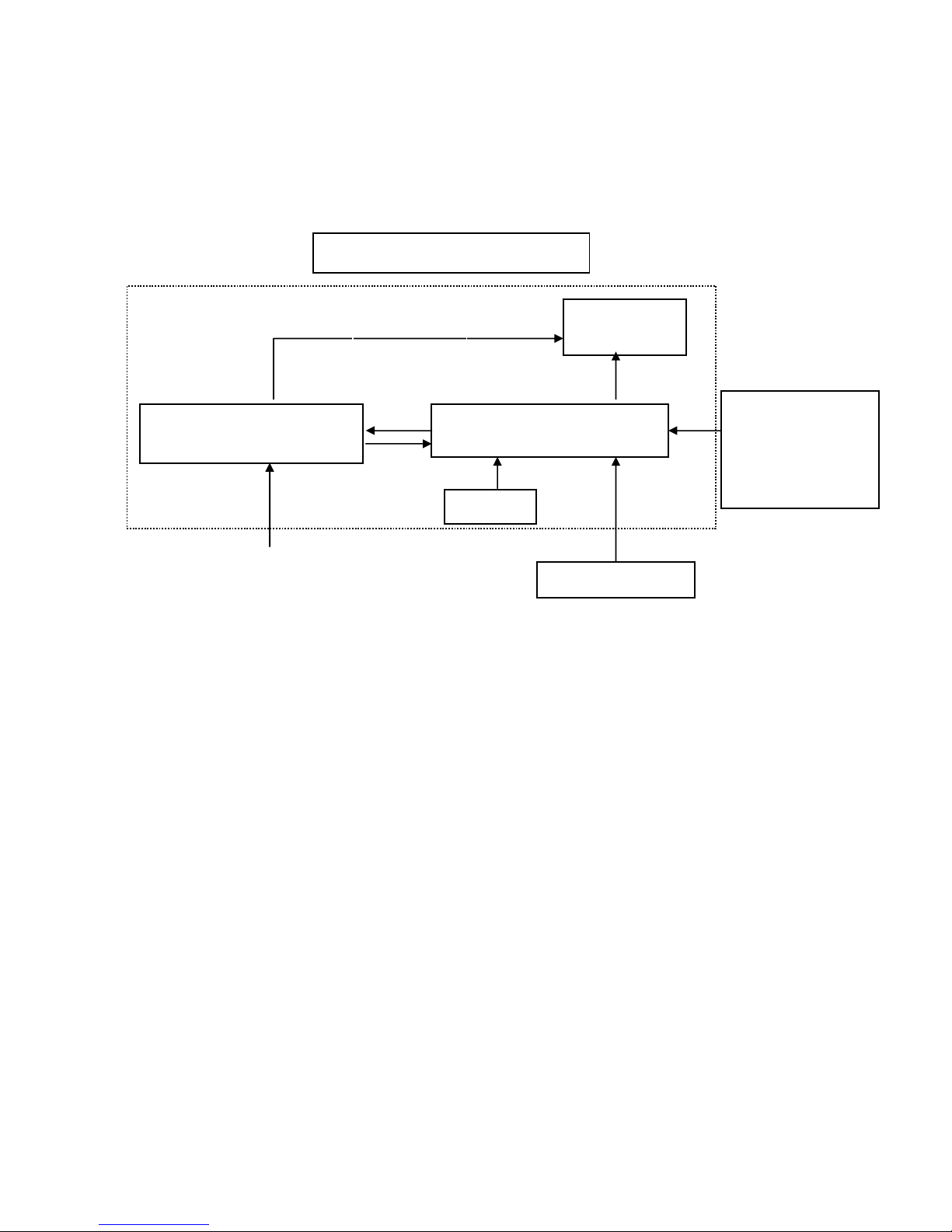
2. LCD Monitor Description
The LCD MONITOR will contain a main board, an inverter/power board, keypad board, which house the flat
panel control logic, brightness control logic and DDC.
The power board will provide AC to DC Inverter voltage to drive the backlight of panel and the main board chips
each voltage.
Video signal, DDC
Power board
(
Include: inverter and adapter)
Flat Panel and
CCFL backlight
Main Board
Keyboard
RS232 Connector
For white balance
adjustment in factory
mode
CCFL Drive.
AC-IN
100V-240V
Monitor Block Diagram
HOST Computer
6
3. Operation instructions
3.1 General Instructions
Press the power button to turn the monitor on or off. The other control buttons are located at front panel of the
monitor. By changing these setting s, the picture ca n be adjusted to your personal preferences.
-
The power cord should be connected.
-
Connect the video cable from the monitor to the video card.
-
Press the power button to turn on the monitor, the power indicator will light up.
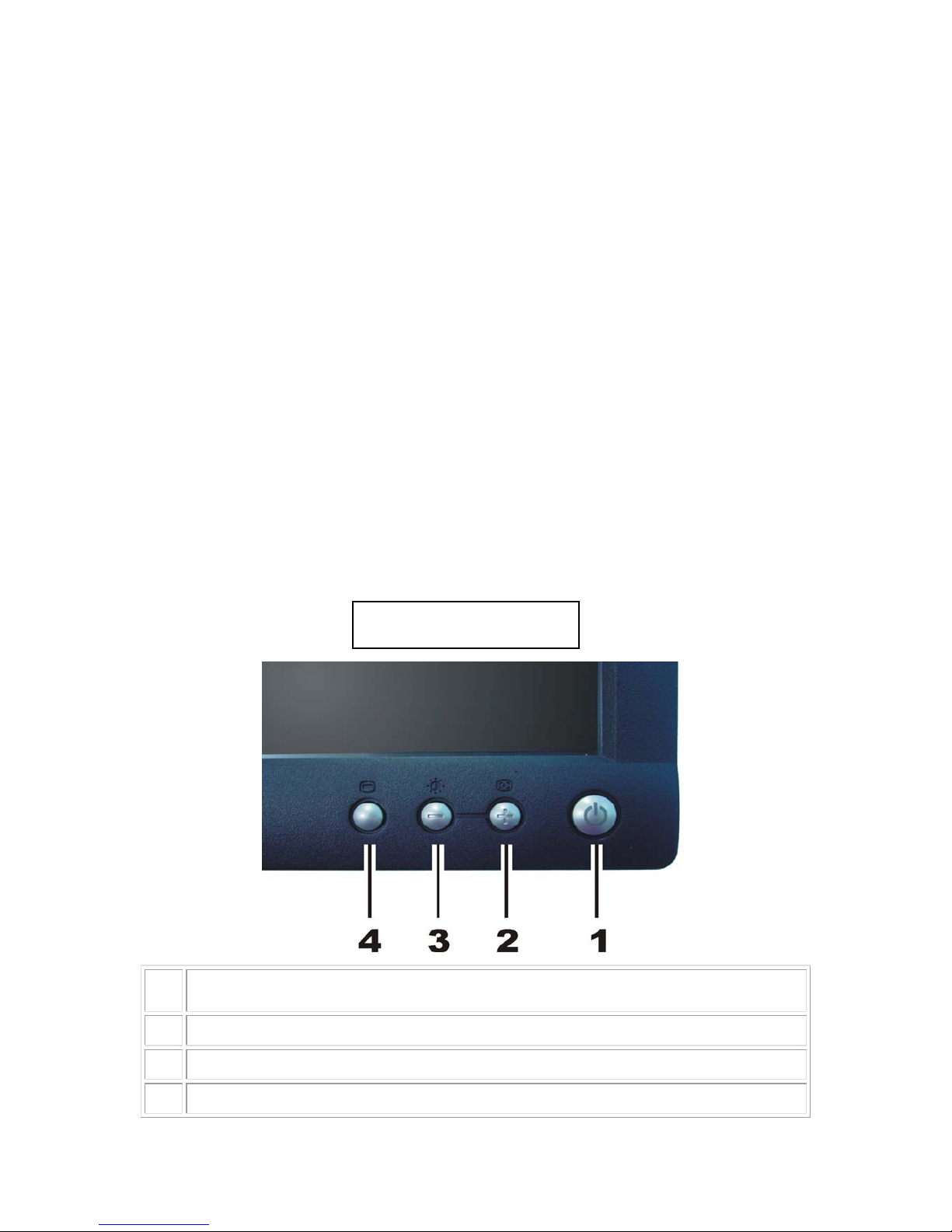
3.2 Control Buttons
Power Button: When pressed, the monitor enters the off mode, and the LED turns blank. Press again to
restore normal status.
Brightness Button: The Brightness Button is used to select the Brightness/Contrast adjust functions.
Press to switch functions or adjust settings.
Auto Adjust Key: The Auto Adjust Key is used to automatically set the H Position, V
Position, Clock and Phase.
Power Indicator:
Green — Power On mode.
Amber — Power Saving mode.
Blank —Power Off Mode.
1 Power On/Off button with LED Indicator
2 Auto Adjust and + button
3 Brightness / Contrast Hotkey and - button
4 Menu button
Control Button
7
3.3 Adjusting the Picture
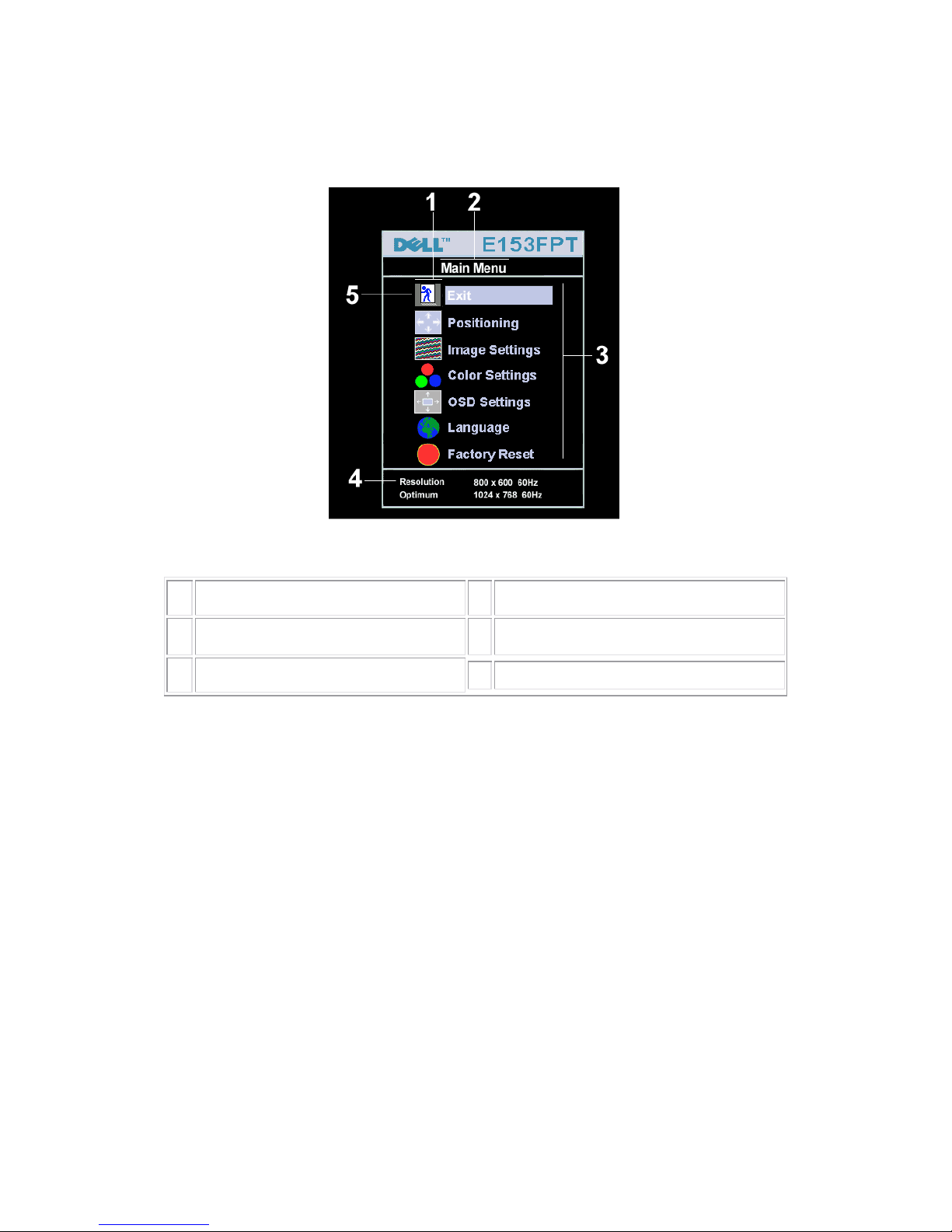
1. With the menu off, push the 'MENU' button to open the OSD system and display the main features menu.
1
Function icons
4
Resolution
2
Main Menu
5
Menu icon
3
Sub-Menu name
2. Push the - and + buttons to move between the function icons. As you move from one icon to another, the
function name is highlighted to reflect the function or group of functions (sub-menus) represented by that
icon. See the table below for a complete list of all the functions available for the monitor.
3. Push the 'MENU' button on ce to activate the highli ghted function; Push -/+ to select the desired parameter,
push menu to enter the slide bar
then use the - and + buttons, according to the indicators on the menu, to make your changes.
4. Push the 'Menu' button once to return to the main menu to select another function or push the 'Menu'
button two or three times to exit from the OSD.
8
OSD Table:
Icon Menu Name and
Sub-menus
Description
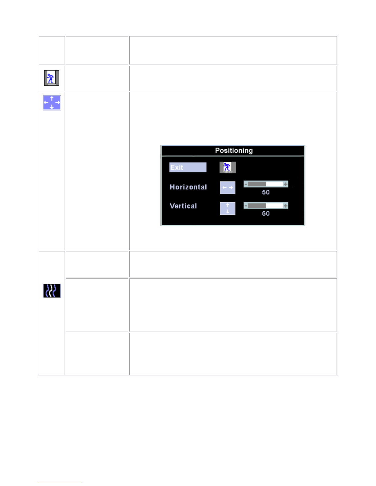
EXIT
This is used to exit out of the 'Main menu'.
Positioning:
Horizontal
Vertical
'Positioning' moves the viewing area around on the monitor screen.
When making changes to either the 'Horizontal' or 'Vertical' settings, no changes
will occur to the size of the viewing area; the image will simply be shifted in
response to your selection/change.
Minimum is '0' (-). Maximum is '100' (+).
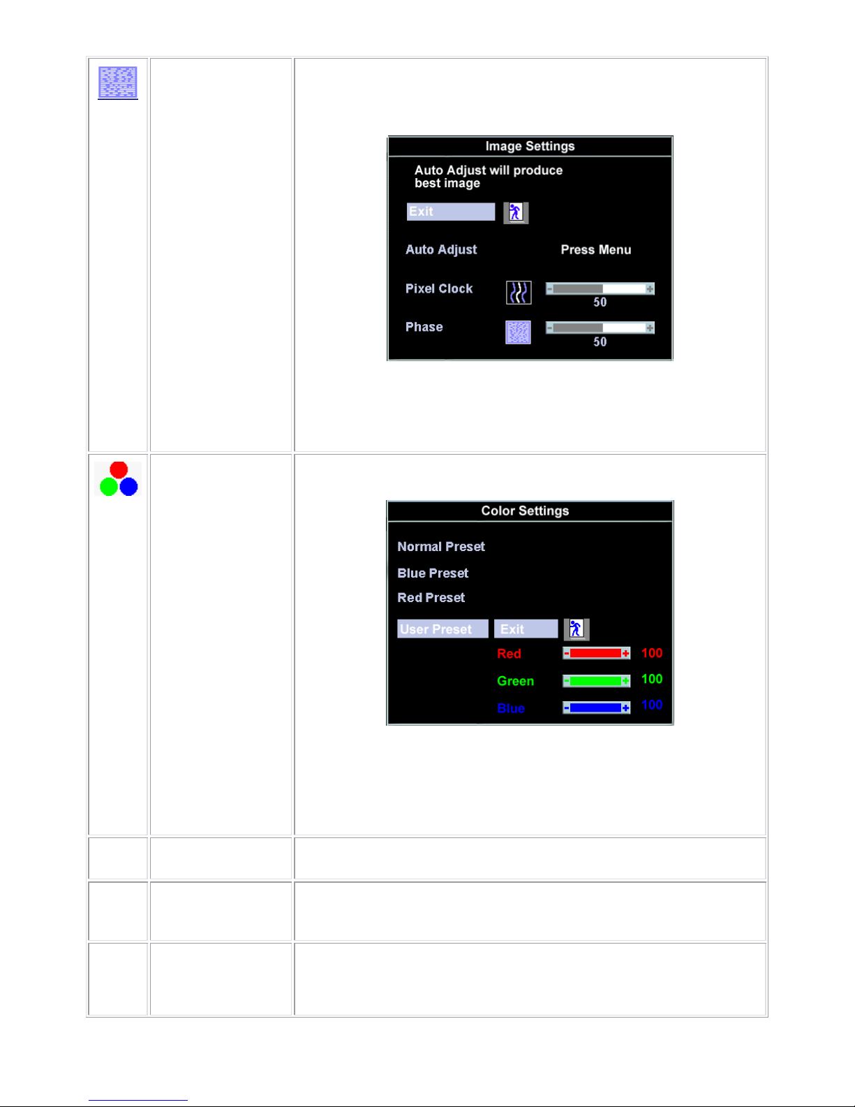
Image settings:
Auto Adjust Even though your computer system can recognize your new flat pa nel monito r on
startup, the 'Auto Adjustment' function will optimize the display settings for use
with your particular setup.
Pixel Clock The 'Phase' and 'Pixel Clock' adjustments allow you to more closely adjust your
monitor to your preference. These settings are accessed through the main OSD
menu, by selecting 'Image Settings'.
Use the - and + buttons to adjust away interference. Minimum: 0 ~ Maximum: 100
9
Phase If satisfactory results are not obtained using the 'Phase' adjustment, use the 'Pixel
Clock' adjustment and then use 'Phase' again.
Color Settings:
'Color Settings' adjusts the color temperature and saturation.
Normal Preset 'Normal Preset' is selected to obtain the default (factory) color settings.
Blue Preset 'Blue Preset' is selected to obtain a bluish tint. This color setting is typically used
for text based applications (Spreadsheets, Programming, Text Editors etc.).
Red Preset 'Red Preset' is selected to obtain a redder tint. This color setting is typically used
for color intensive applications (Photograph Image Editing, Multimedia, Movies
etc.).
10
User Preset 'User Preset': Use the plus and minus buttons to increase or decrease each of the
three colors (R, G, B) independently, in single digit increments, from '0' to '100'.
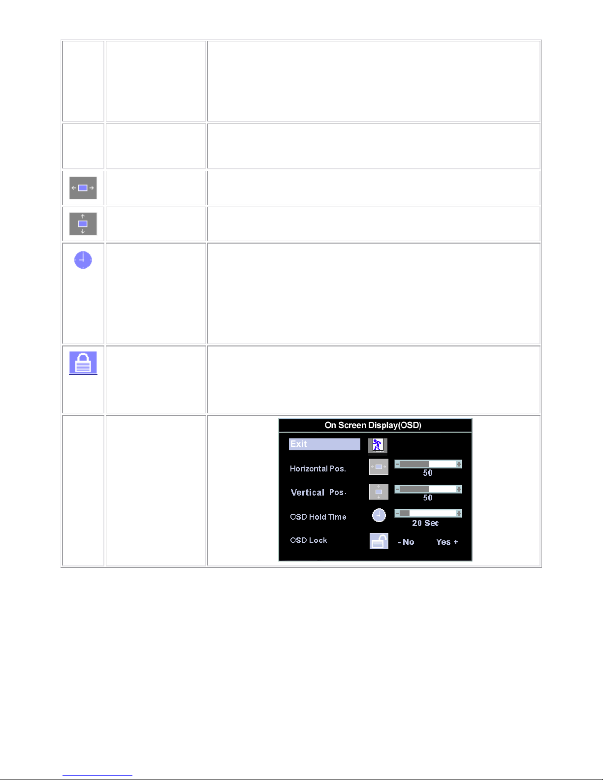
OSD Settings:
Each time the OSD opens, it displays in the same location on the screen. 'OSD
Settings' (horizontal/vertical) provides control over this location.
Horizontal Position
- and + buttons move OSD to the left and right.
Vertical Position
- and + buttons move OSD down and up.
OSD Hold Time: The OSD stays active for as long as it is in use.
'OSD Hold Time': Sets the length of time the OSD will remain active after the last
time you pressed a button.
Use the - and + buttons to adjust the slider in 5 second increments, from 5 to 60
seconds.
OSD Lock 'OSD Lock': Controls user access to adjustments. When 'Yes' (+) is selected, no
user adjustments are allowed. All buttons are locked except the menu button.
A
ll buttons can be locked or unlocked when the 'Menu' button is pushed and held
for over 15 seconds.
11
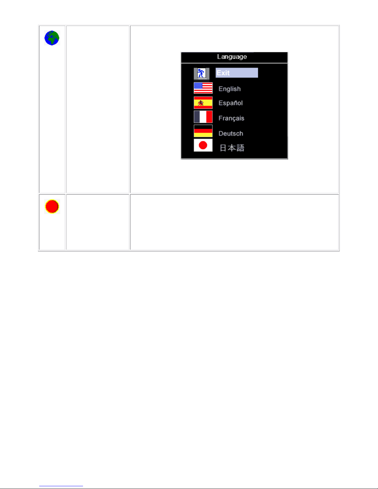
Language:
Language sets the OSD to display in one of five languages (English, Español,
Français, Deutsch, Japanese).
Factory Reset:
'Factory Reset' returns the settings to the factory preset values for the selected
group of functions.
‘Exit’ is used to exit out of 'Factory Reset' menu.
For 'All settings', all user adjustable settings are reset at one time except
'Language settings'.
12
4. Input/Output Specification
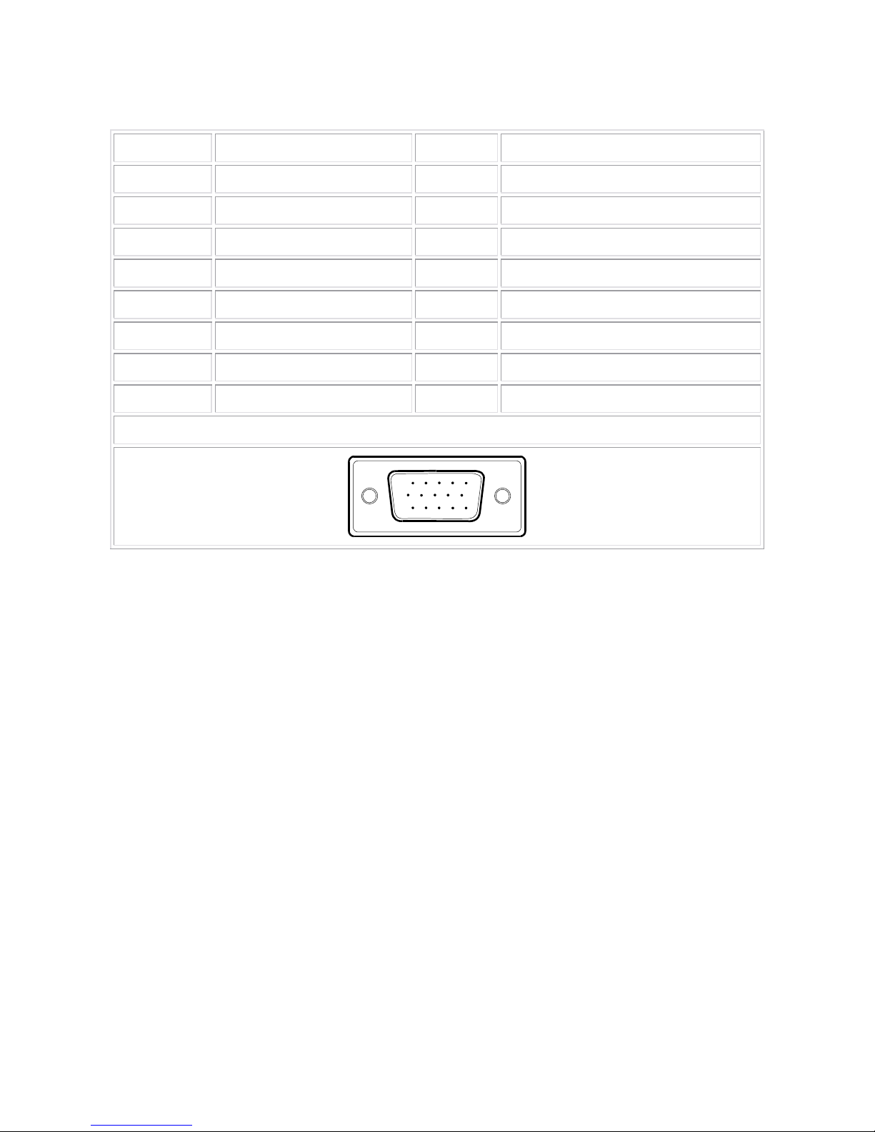
4.1 Input Signal Connector
PIN NO. DESCRIPTION PI N NO. DESCRIPTION
1. Red Video 9. +5V (From PC)
2. Green Video 10. GND
3. Blue Video 11. GND
4. GND 12. DDC-Serial Data
5. GND 13. H-Sync
6. R-Ground 14. V-Sync
7. G-Ground 15. DDC-Serial Clock
8. B-Ground
VGA Connect or layout
15
6
10
11 15
13
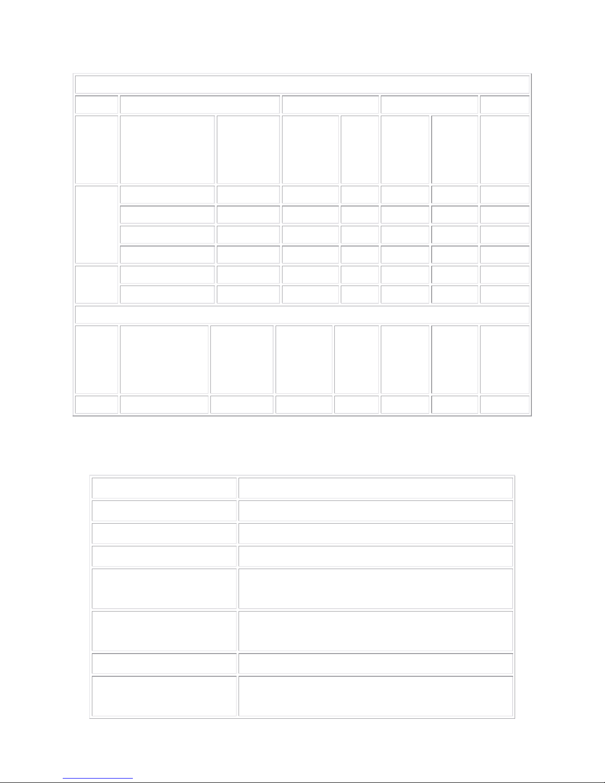
4.2 Factory Preset Display Modes
VESA MODES
Horizontal Vertical
Mode Resolution Total
Nominal
Frequency
+/- 0.5kHz
Sync
Polarit
y
Nominal
Freq.
+/- 1 Hz
Sync
Polarity
Nominal
Pixel
Clock
(MHz)
640x480@60Hz 800 x 525 31.469 N 59.940 N 25.175
640x480@75Hz 840 x 500 37.500 N 75.00 N 31.500
800x600@60Hz 1056 x 628 37.879 P 60.317 P 40.000
VGA
800x600@75Hz 1056x625 46.875 P 75.000 P 49.500
1024x768@60Hz 1344x806 48.363 N 60.004 N 65.000
XGA
1024x768@75Hz 1312x800 60.023 P 75.029 P 78.750
IBM MODES
Mode Resolution Total
Nominal
Frequency
+/- 0.5kHz
Sync
Polarity
Nominal
Freq.
+/- 1 Hz
Sync
Polarity
Nominal
Pixel
Clock
(MHz)
DOS 720x400@70Hz 900 x 449 31.469 N 70.087 P 28.322
4.3 Power Supply Requirements
A/C Line voltage range 100 V ~ 240 V± 10 %
A/C Line current 1.5A (RMS) max
A/C Line frequency range 50 ± 3Hz, 60 ± 3Hz
Input Volt age transients 280 volts AC for 10 sec @40℃
Synchronization input signals
Separate horizontal and vertical;
3.3V CMOS or 5V TTL level, positive or negative sync.
Peak surge current
< 60A peak at 240 VAC and cold starting
< 30A peak at 120VAC and cold starting
Leakage current < 3.5mA
Power line surge
No advance effects (no loss of information or defe ct)
With a maximum of 1 half-wave missing per second
14
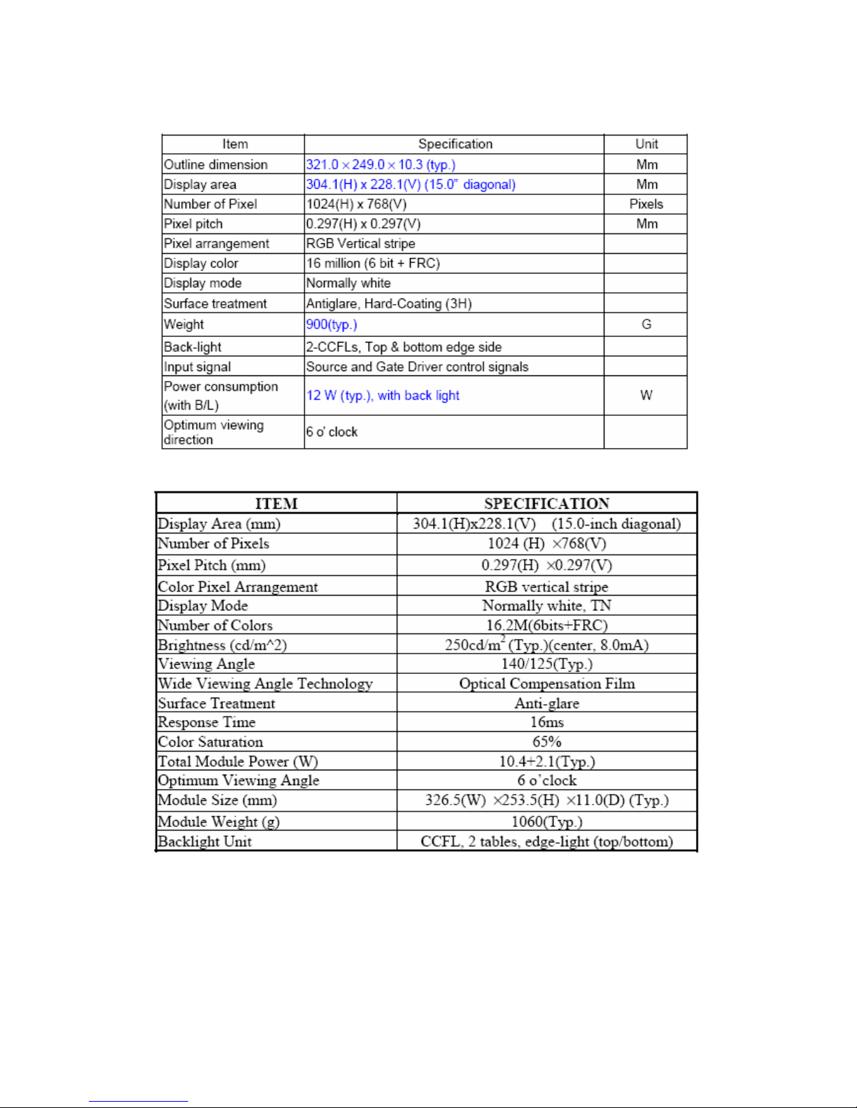
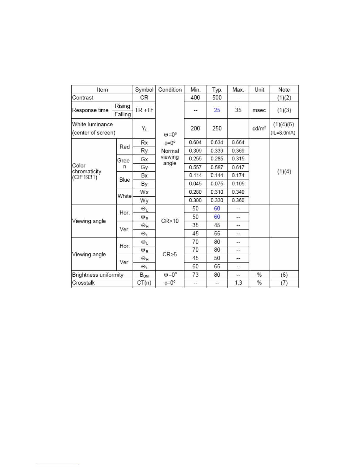
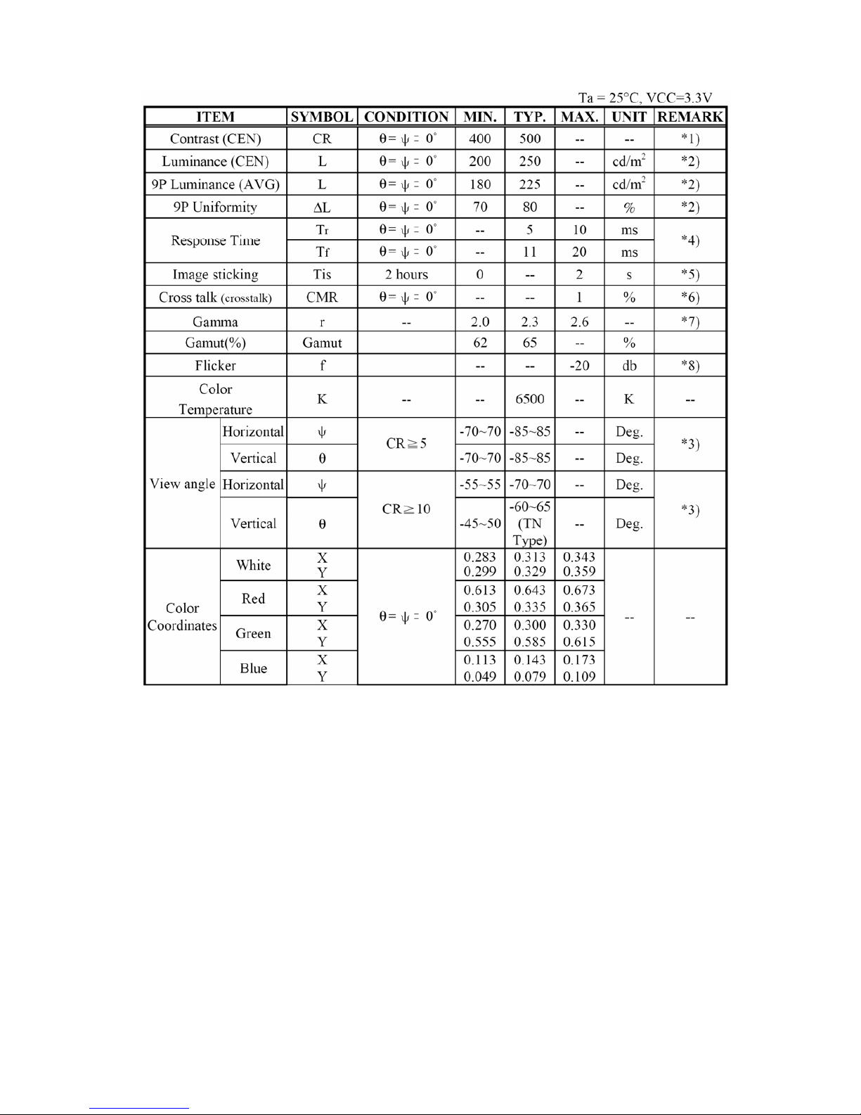
4.4 Panel Specification
4.4.1 Display Characteristics
(For HSD panel)
(For CPT panel)
15
4.4.2 Optical Characteristics
The optical characteristics are measured under stable conditions as follows:
(For HSD panel)
Measuring surrounding:
dark room , IL=8.0±0.1mA, FL=55KHZ, FDCLK=65MHZ, Ta=25±2ºC
16
(For CPT panel)
17
4.5 Touch Panel Specification:
Input Method
16mm dia. Silicon ”finger”
Average Activation Force
Less than 1.00 N
Visible Light Transmission
>80%
Haze
<13%
Operating Voltage
2.5V - 5.0V
Contact current
20mA (maximum)
Circuit close resistance
≤150Ω
Circuit open resistance
≥15MΩ
Temperature
-20°C to +50°C
Operating
Humidity
Less than 90% RH
Temperature
-40°C to -21°C (Minimum)
+51°C - +70°C (Maximum)
Storage
Humidity
20%-50% RH

18
5. Block Diagram
5.1 Exploded View
19
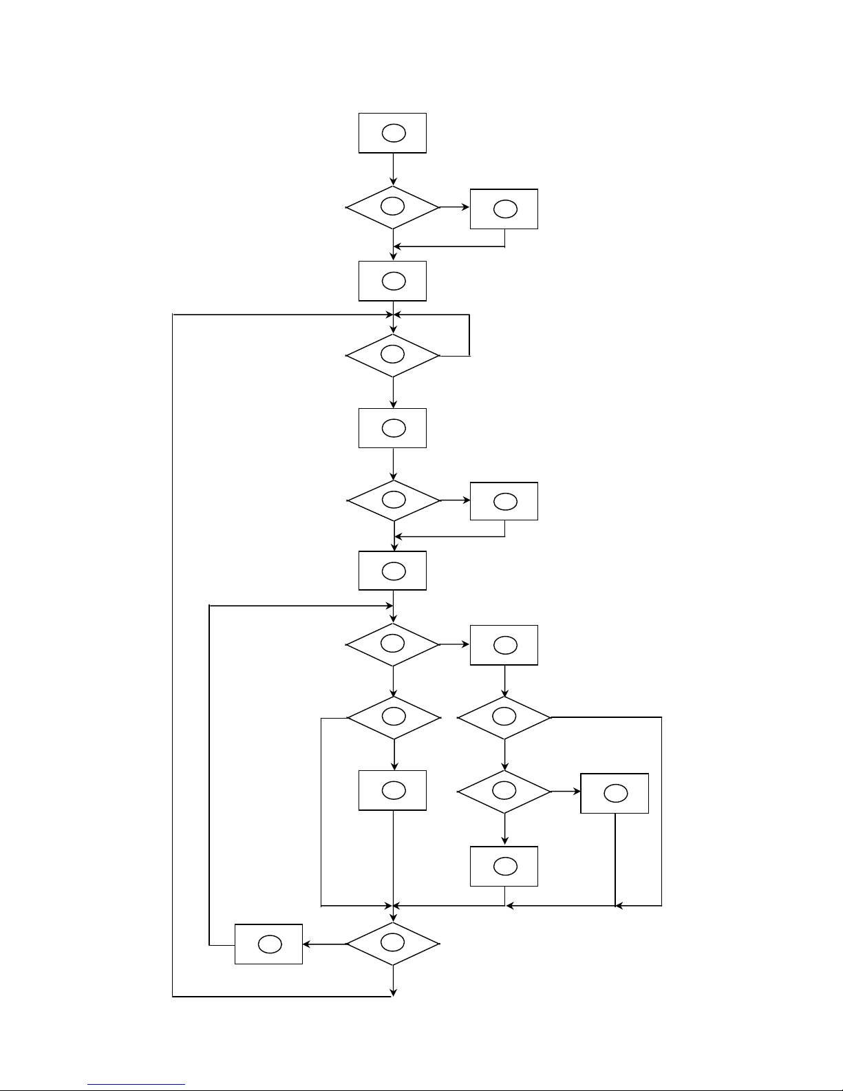
5.2 Software Flow Chart
2
N
Y
5
Y
N
10
Y
N
12
Y
N
7
Y
N
6
4
3
8
9
14
11
13
Y
N
15
Y
N
16
17
19
Y
N
18

20
Remark:
1) MCU Initializes.
2) Is the EEprom blank?
3) Program the EEprom by default values.
4) Get the PWM value of brightness from EEprom.
5) Is the power key pressed?
6) Clear all global flags.
7) Are the AUTO and SELECT keys pressed?
8) Enter factory mode.
9) Save the power key status into EEprom. Turn on the LED and set it to green color. Scalar initializes.
10) In standby mode?
11) Update the lifetime of back light.
12) Check the analog port, are there any sig nals coming?
13) Does the scalar send out an interrupt request?
14) Wake up the scalar.
15) Are there any signals coming from analog port?
16) Display "No connection Check Signal Cable" message. And go into standby mode after the message
disappears.
17) Program the scalar to be able to show the coming mode.
18) Process the OSD display.
19) Read the keyboard. Is the power key pressed?
21
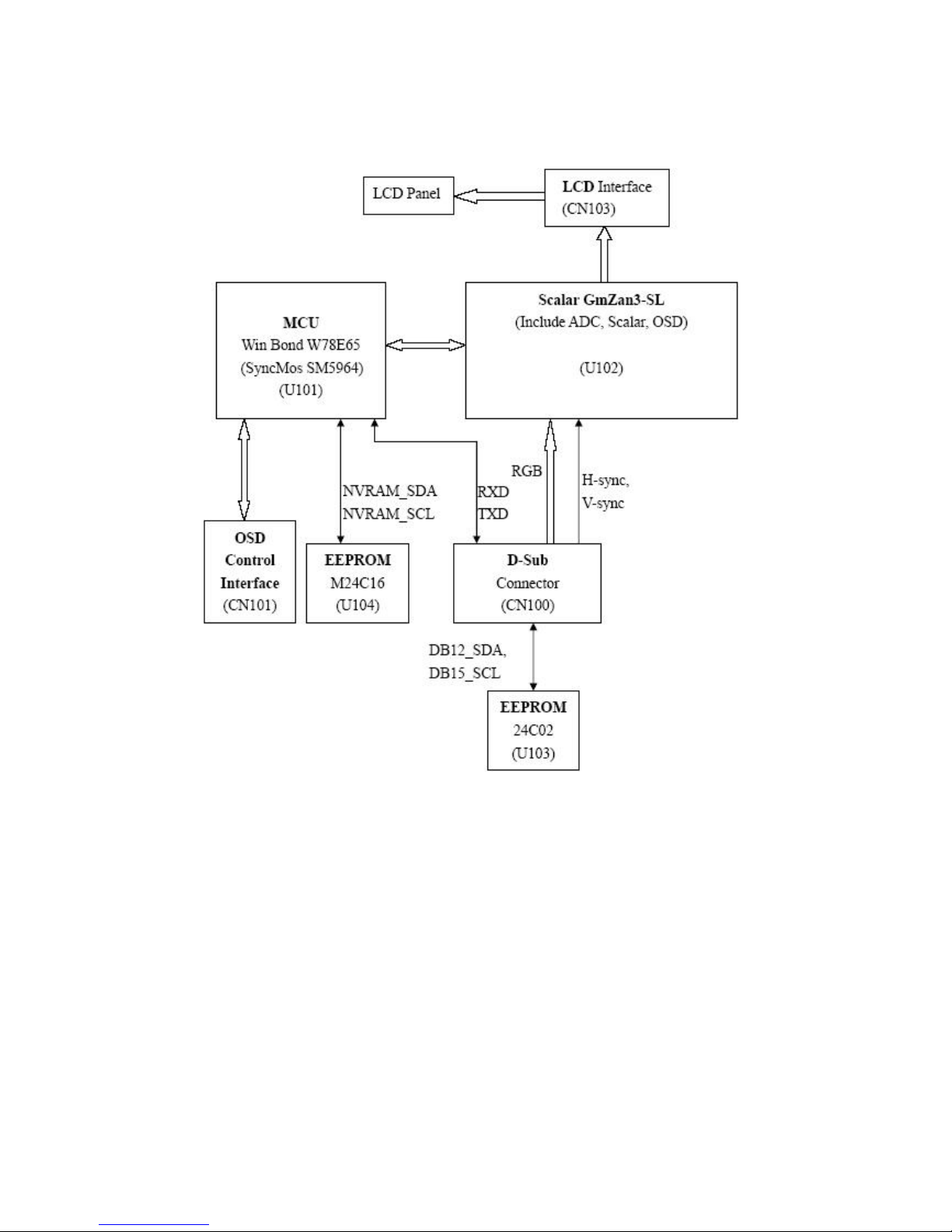
5.3 Electrical Block Diagram
5.3.1 Main Board
 Loading...