

Dell E152FPc Service Manual
DELL E152FPc
SERVICE MANUAL
15” LCD MONITOR
DELL E152FPc
THESE DOCUMENTS ARE FOR REPAIR SERVICE INFORMATION ONLY. EVERY REASONABLE EFFORT
HAS BEEN MADE TO ENSURE THE ACCURACY OF THIS MANUAL; WE CANNOT GUARANTEE THE
ACCURACY OF THIS INFORMA TION AFTER THE DATE OF PUBLICATION AND DISCLAIMS RE LIABILITY
FOR CHANGES, ERRORS OR OMISSIONS.
MANUFACTURE DATA: MAR.-20-2005
1

DELL E152FPc
Table of Contents
TABLE OF CONTENTS...............................................................................................................2
1. MONITOR SPECIFICATIONS .................................................................................................4
2. LCD MONITOR DESCRIPTION ..............................................................................................5
3. OPERATING INSTRUCTIONS................................................................................................6
3.1 GENERAL INSTRUCTIONS...............................................................................................6
3.2 CONTROL BUTTONS........................................................................................................6
3.3 ADJUSTING THE PICTURE...............................................................................................7
4. INPUT/OUTPUT SPECIFICATION........................................................................................10
4.1 INPUT SIGNAL CONNECTOR.........................................................................................10
4.2 FACTORY PRESET DISPLAY MODES............................................................................10
4.3 POWER SUPPLY REQUIREMENTS...............................................................................11
4.4 PANEL SPECIFICATION..................................................................................................11
5. BLOCK DIAGRAM................................................................................................................14
5.1 MONITOR EXPLODED VIEW..........................................................................................14
5.2 SOFTWARE FLOW CHART.............................................................................................15
5.3 ELECTRICAL BLOCK DIAGRAM.....................................................................................17
6. SCHEMATIC..........................................................................................................................18
6.1 MAIN BOARD...................................................................................................................18
6.2 PWPC BOARD.................................................................................................................22
7. PCB LAYOUT........................................................................................................................25
7.1 MAIN BOARD...................................................................................................................25
7.2 PWPC
7.3 KEYPAD BOARD .............................................................................................................28
8. MAINTAINABILITY................................................................................................................28
8.1 EQUIPMENTS AND TOOLS REQUIREMENT.................................................................28
8.2 TROUBLE SHOOTING ....................................................................................................29
BOARD.................................................................................................................27
9.WHITE-BALANCE, LUMINANCE ADJUSTMENT.................................................................35
10. EDIT CONTENT...................................................................................................................36
11. BILL OF MATERIAL LIST ...................................................................................................37
12.DEFINITION OF PIXEL DEFECTS.......................................................................................53
2

DELL E152FPc
Revision List
Revision Date Revision History TPV model
A00 Mar-20-2005 Initial Release
A01 April-25-2006
Add” Max Brightness measurement” on
Page36
3
DELL E152FPc
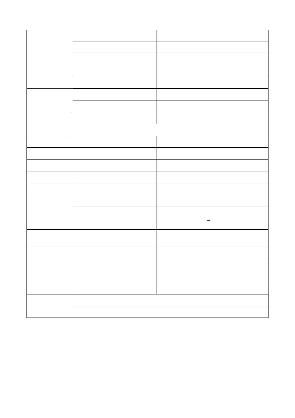
1. MONITOR SPECIFICATIONS
Driving system TFT Color LCD
Flat Panel
Input
Size 38.1mm(15.0")
Pixel pitch 0.297mm(H) x 0.297mm(V)
Viewable angle 120˚ (H) 100˚ (V)
Response time (typ.) 25 ms
Video Analog Only
Sync. Type H/V TTL Separate and Composite Sync.
H-Frequency 30kHz – 63kHz
V-Frequency 56-76Hz
Display Colors Over 16.2 million Colors
Dot Clock 80MHz
Max. Resolution 1024 x 768
Plug & Play VESA DDC2BTM
ON Mode
<25W
Power Consumption
Weight (N. W . )
OFF Mode
Maximum Screen Size
Power Source
Environmental
Considerations
Packaged 5.31Kgs Unit
Unpackaged 3.50Kgs Unit
<35W(For Samsung XH panel)
<
1W
Horizontal : 11.9”(304.1mm)
Vertical:8.9”(228.1mm)
110~240VAC,50~60Hz
Operating Temp: 5°C to35°C
Storage Temp.:-20°C to80°C
4
DELL E152FPc
r
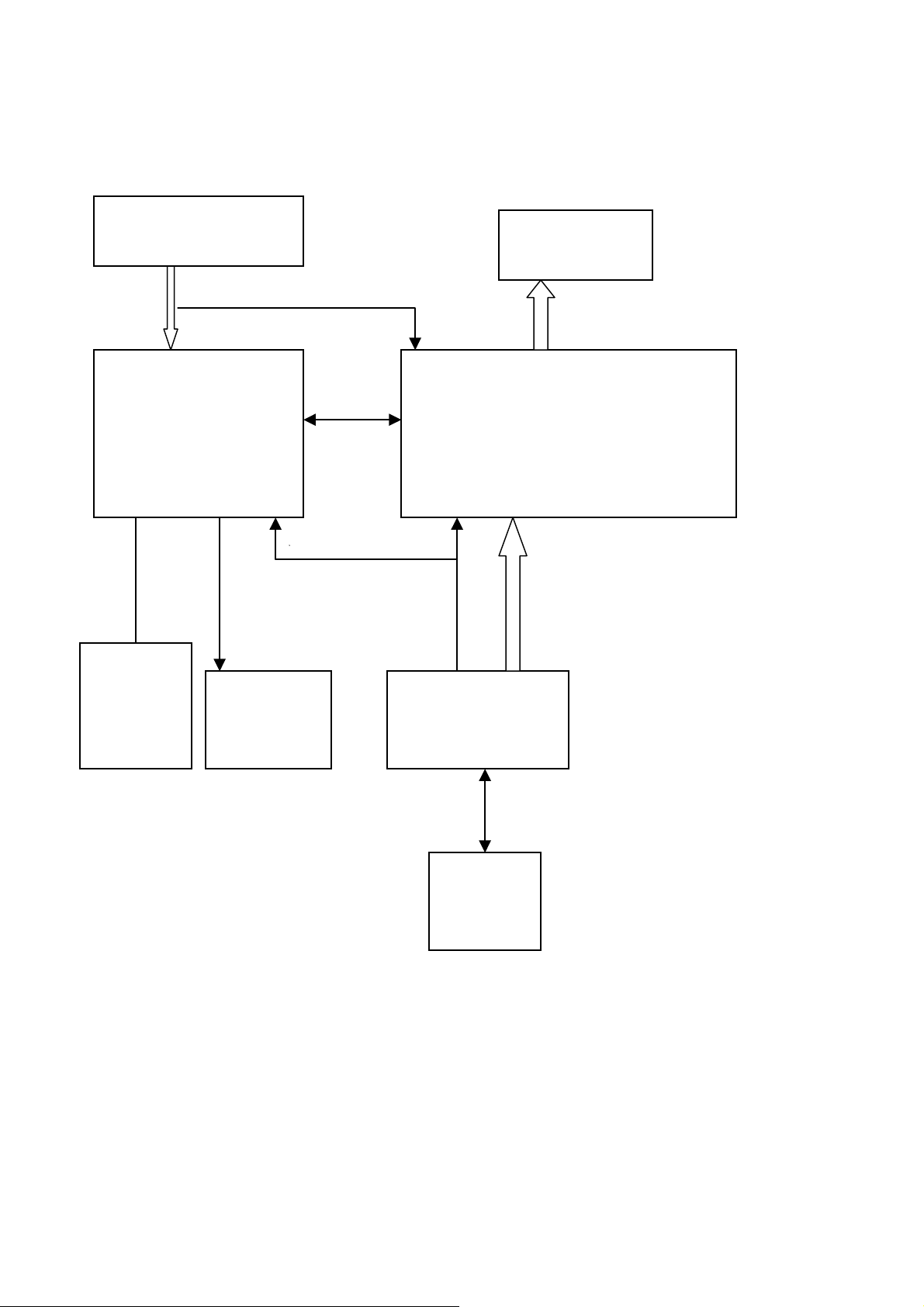
2. LCD MONITOR DESCRIPTION
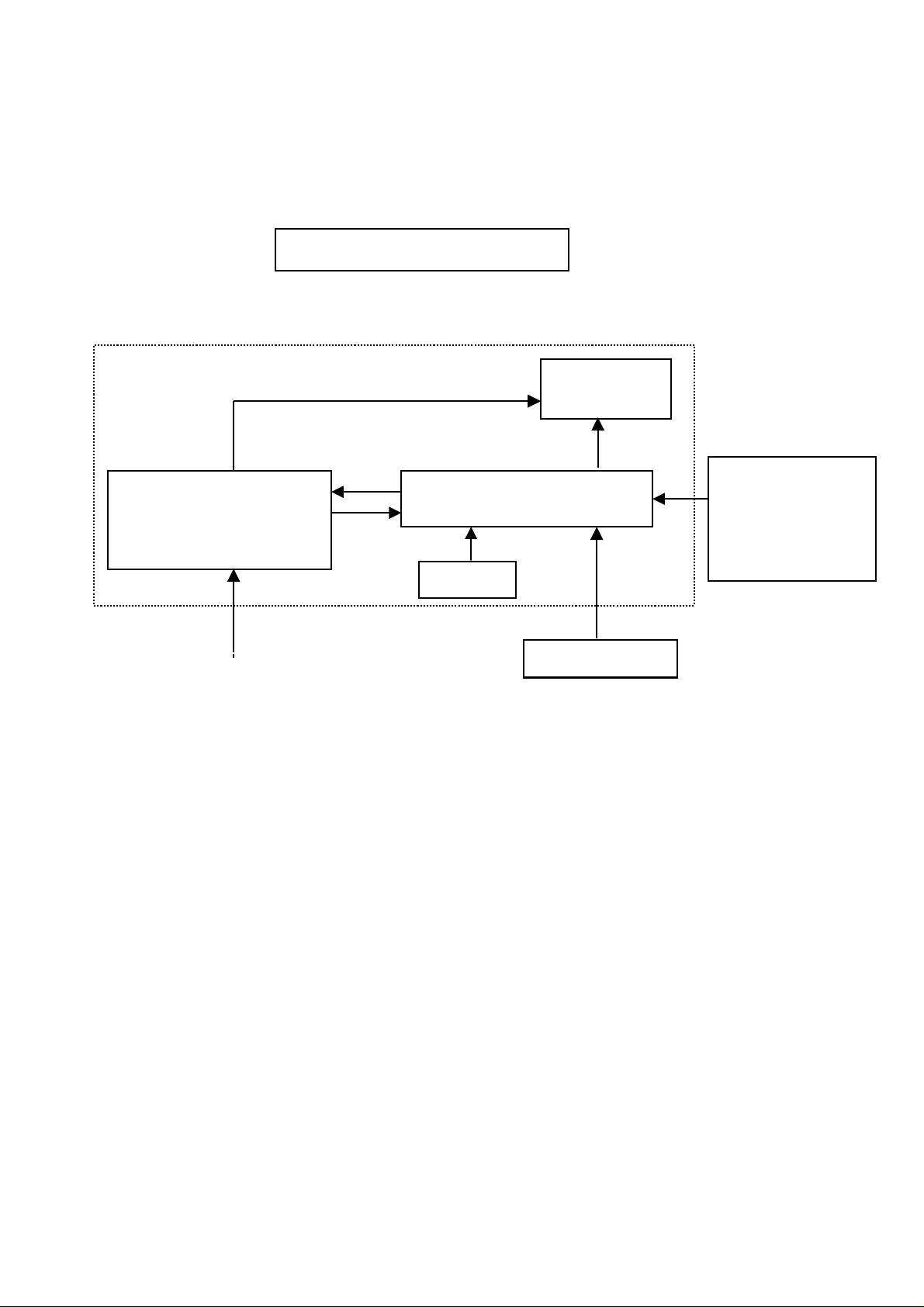
The LCD MONITOR will contain a main board, an internal PWPC board, keypad board, which house the flat panel
control logic, brightness control logic and DDC.The internal PWPC board will drive the backlight of panel and the
DC-DC conversion. and provides the 5V DC-power to main board.
Monitor Block Diagram
CCFL Drive.
Flat Panel and
CCFL backlight
(Include adapter and Inverte
PWPC board
board)
Keyboard
Main Board
Video signal, DDC
RS232 Connector
For white balance
adjustment in factory
mode
AC-IN
Host Computer
100-240V
5

DELL E152FPc
3. OPERATING INSTRUCTIONS
3.1 GENERAL INSTRUCTIONS
Press the power button to turn the monitor on or off. The other control buttons are located at front panel of the
monitor. By changing these settings, the picture can be adjusted to your personal preferences.
-The power cord should be connected.
-Connect the video cable from the monitor to the video card.
-Press the power button to turn on the monitor, the power indicator will light up.
3.2 CONTROL BUTTONS
-Power Button:
When pressed, the monitor enters the off mode, and the LED turns blank. Press again to restore normal status.
-Brightness Button:
The Brightness Button is used to select the Brightness/Contrast adjust functions. Press to switch functions or
adjust settings.
-Auto Adjust Key:
The Auto Adjust Key is used to automatically set the H Position, V Position, Clock and Phase.
-Power Indicator:
Green — Power On mode.
Orange — Power Saving mode.
Blank —Power Off Mode.
Control Buttons
A.Buttons for the OSD menu (On-Screen-display)
B. Brightness/Contrast menu Button
C. Auto Adjust Button
D. Power On/Off Button and indicator
6
DELL E152FPc
3.3 ADJUSTING THE PICTURE
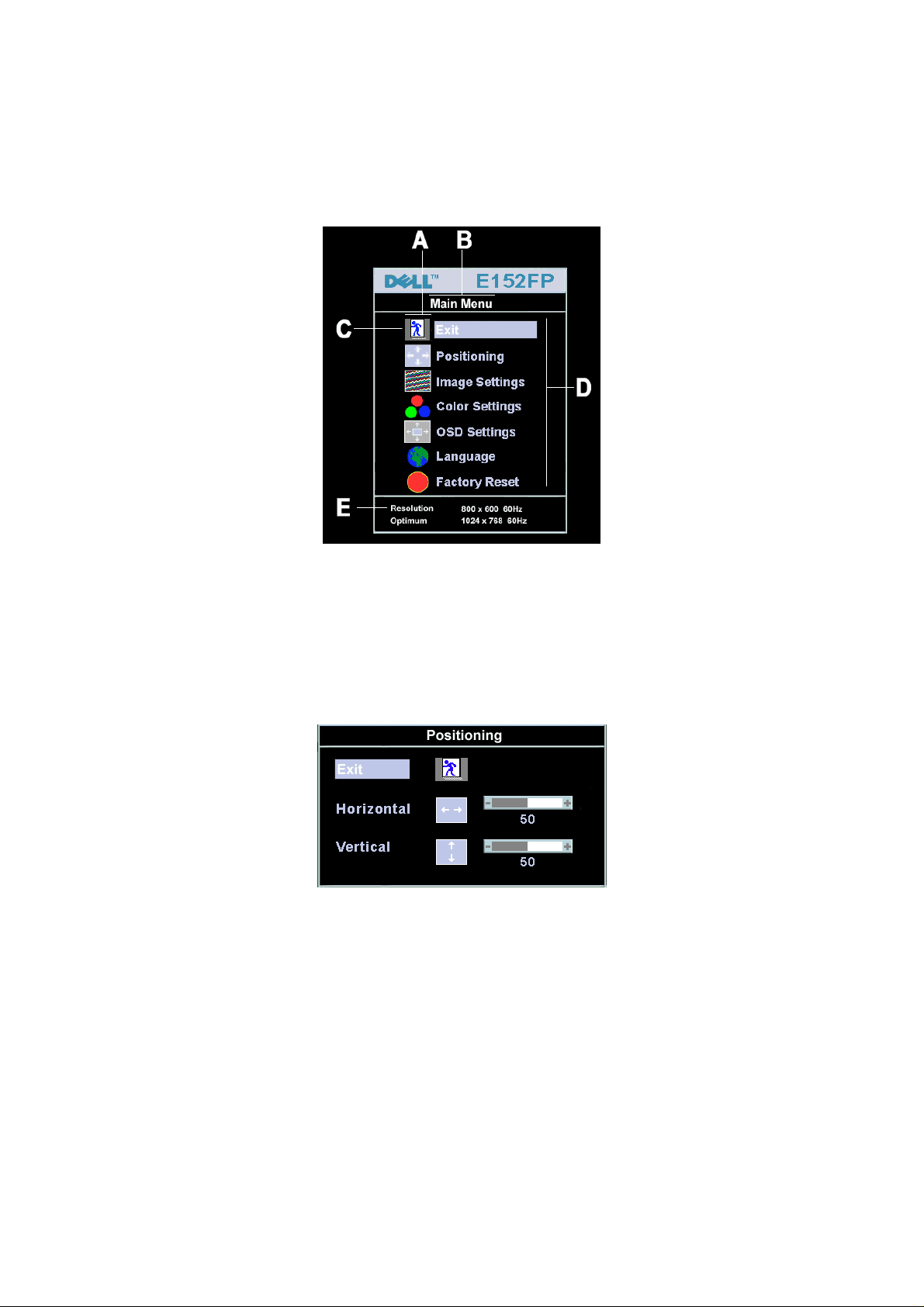
To set the OSD menu, perform the following steps:
Briefly press the SELCT / MENU button to activate the OSD menu.
The main menu appears on the screen with icons for the setting functions.
The first symbol (Exit) is highlighted.
Necessary, press the- or + button to mark another icon (e.g. Positioning).
Press the SELECT/MENU button to select the highlighted icon.
The corresponding setting window (here: Positioning) is displayed.
The first symbol (Exit) is highlighted.
If necessary, press the – or + button to mark the desired icon.
Press the SELECT/MENU button to select the highlighted function.
Press the – or + button to adjust the value for the selected function.
Press the SELECT/MENU button to exit the function.
Press the SELECT/MENU button to exit the sub-menu when “Exit” function is highlighted;
All changes are stored automatically.
7
DELL E152FPc
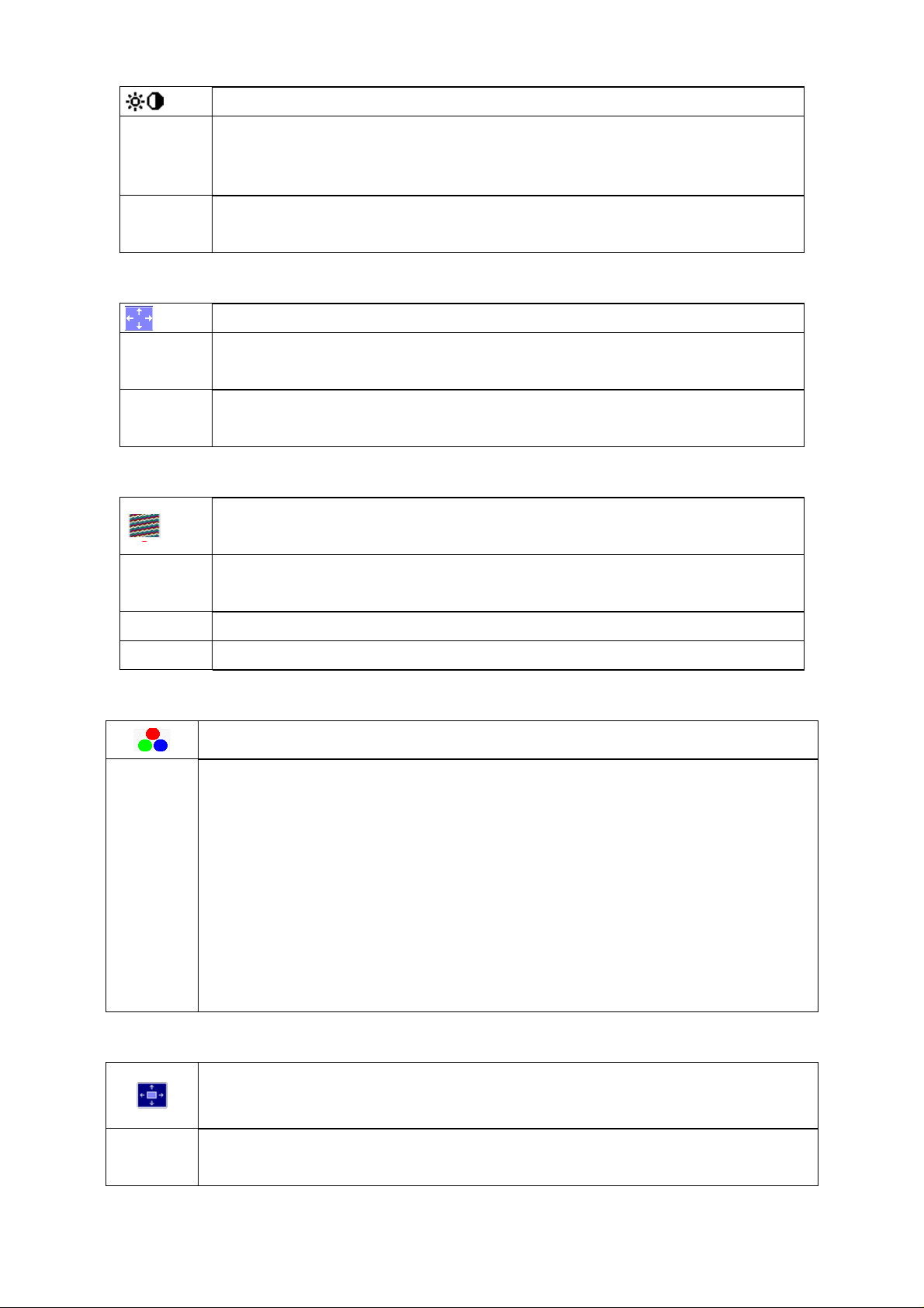
Adjusting the brightness and contrast
Brightness Setting the brightness of the display
Contrast Setting the contrast of the display
Adjusting size and position
H-Position Adjusting the horizontal position
V-Position Adjusting the vertical position
Setting Image
Calling the Brightness / Contrast setting window using Brightness button.
With this function you change the brightness of the background lighting.
With this function you modify the contrast of bright colour tones.
Calling the Positioning setting window
With this function you move the picture to the left or to the right.
With this function you move the picture up or down.
Calling the Image setting window
Auto Adjust Auto adjust will produce best image automatically , The information of “ Auto Adjust In
Progress” will show;
Pixel clock Adjusting the pixel clock
Phase Adjusting the phase
Setting colour temperature and colours
Calling the Color setting window
Selecting the colour temperature
The colour temperature is measured in K (= Kelvin). You can select from Normal Preset,
Blue Preset, Red Preset to User Preset;
Normal preset
Blue preset
Red preset
User preset
In the user preset setting you can change the colour ratios of the basic colours (red,
green, blue) as required.
= Original colour of the LCD display, it’s 6500K;
=5700Kcolour of the LCD display, it’s 9300K;
=9300K colour of the LCD display, it’s 5700K;
= Setting user-defined colours
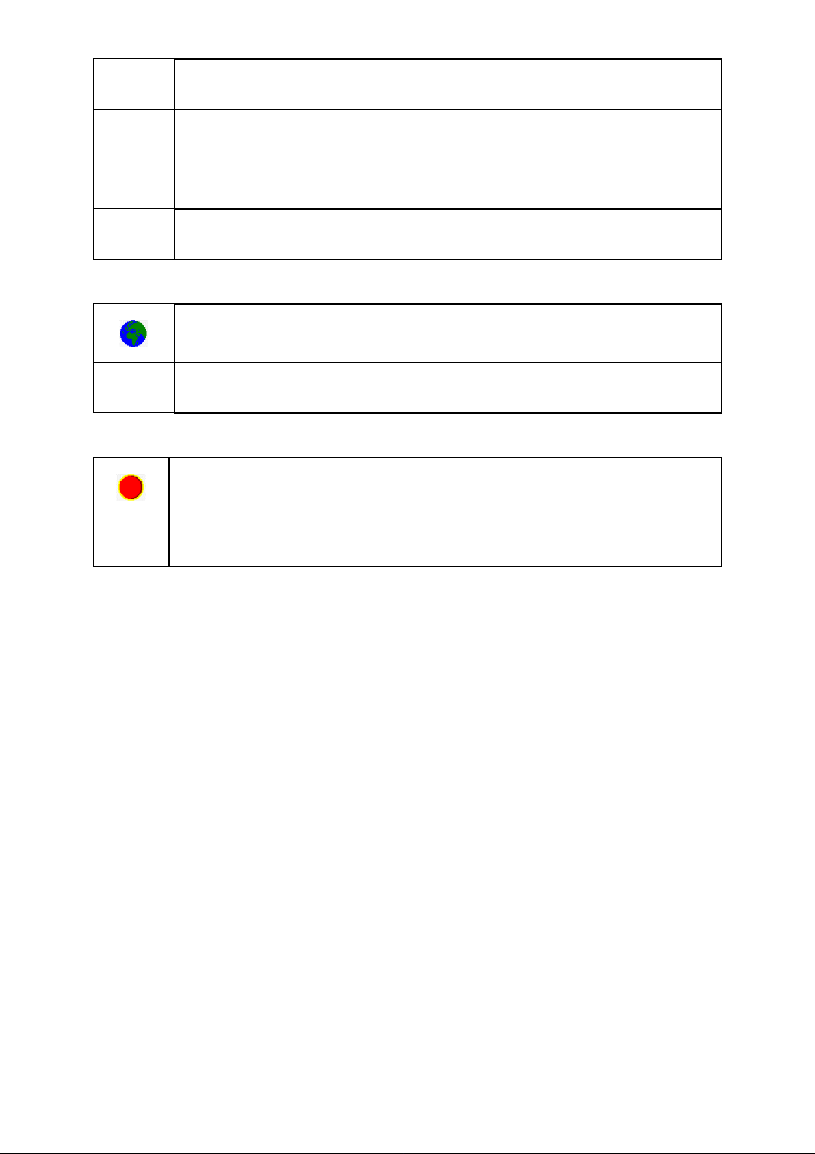
Setting display of the OSD menu
Calling the OSD Set up setting window
Horizontal
Position
Setting the horizontal position of the OSD menu
With this function you move the OSD menu to the left or to the right.
8
DELL E152FPc
Vertical
Position
OSD
Hold Time
OSD
Lock
Setting Language
Factory Reset
Setting the vertical position of the OSD menu
With this function you move the OSD menu up or down.
Setting the display duration of the OSD menu, the default value is 20s;
With this function you select a value from 0 to 60 seconds.
If the set time expires without a setting being made, the OSD menu is automatically faded
out.
Setting the display of the OSD menu lock or unlock.
With this function you select Yes to lock OSD, NO to unlock it.
Calling the Language setting window
With this function you choose between English (default setting), French, German,
Spanish and Japanese as the language for the OSD menu.
Activating the factory settings
With this function all settings except Language of OSD are reset to the factory settings
without prompting for confirmation.
9
DELL E152FPc
4. INPUT/OUTPUT SPECIFICATION
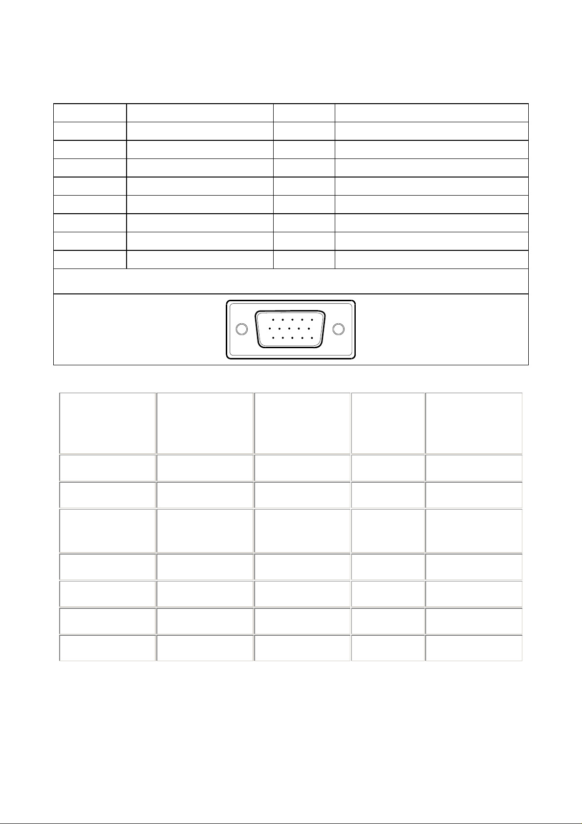
4.1 INPUT SIGNAL CONNECTOR
15-pin D-sub connector
PIN NO. DESCRIPTION PI N NO. DESCRIPTION
1. Red 9. +5V
2. Green 10. Detect Cable
3. Blue 11. Ground
4. Ground 12. DDC-Serial Data
5. Ground 13. H-Sync
6. R-Ground 14. V-Sync
7. G-Ground 15. DDC-Serial Clock
8. B-Ground
VGA Connector layout
4.2 FACTORY PRESET DISPLAY MODES
Horizontal
Display Mode
DOS 720 x 400 31.5 70.1 28.3 -/+
VGA 640 x 480 31.5 60.0 25.18 -/-
VESA 640 x
480
VESA 800 x 600 37.9 60.3 40.0 +/+
VESA 800 x 600 46.9 75.0 49.5 +/+
Frequency (kHz)
37.5 75.0 31.5 -/-
15
6
11 15
10
Vertical
Frequency (Hz)
Pixel Clock
(MHz)
Sync Polarity
(Horizontal /
Vertical)
VESA 1024 x 768 48.4 60.0 65.0 -/-
VESA 1024 x 768 60.0 75.0 78.8 +/+
For ergonomic reasons, a screen resolution of 1024 x 768 pixels is recommended. Because of the technology used
(active matrix) an LCD monitor provides a totally flicker-free picture even with a refresh rate of 60 Hz.
10
DELL E152FPc
4.3 POWER SUPPLY REQUIREMENTS
4.3.1 INPUT REQUIREMENTS
AC INPUT VOLTAGE: 100V ~ 240V
AC INPUT FREQUENCY: 50 ~ 60 HZ
AC INPUT CURRENT: 1.5A MAX
INRUSH CURRENT: 50A MAX AT 220V
LEAKAGE CURRENT: 3.5 mA Max.
4.3.2 OUTPUT REQUIREMENTS
ITEM MIN. TYP. MAX. UNIT REMARK
Output voltage (12V) 11.4 12 12.6 V
Output current (12V) 0 1.5 2.0 A
Output voltage ( 5V) 4.75 5.0 5.25 V
Output current (5V) 0 1.5 2.0 A
Ripple & Noise (12V) 200 mV
Ripple & Noise (5V) 100 mV
4.4 PANEL SPECIFICATION
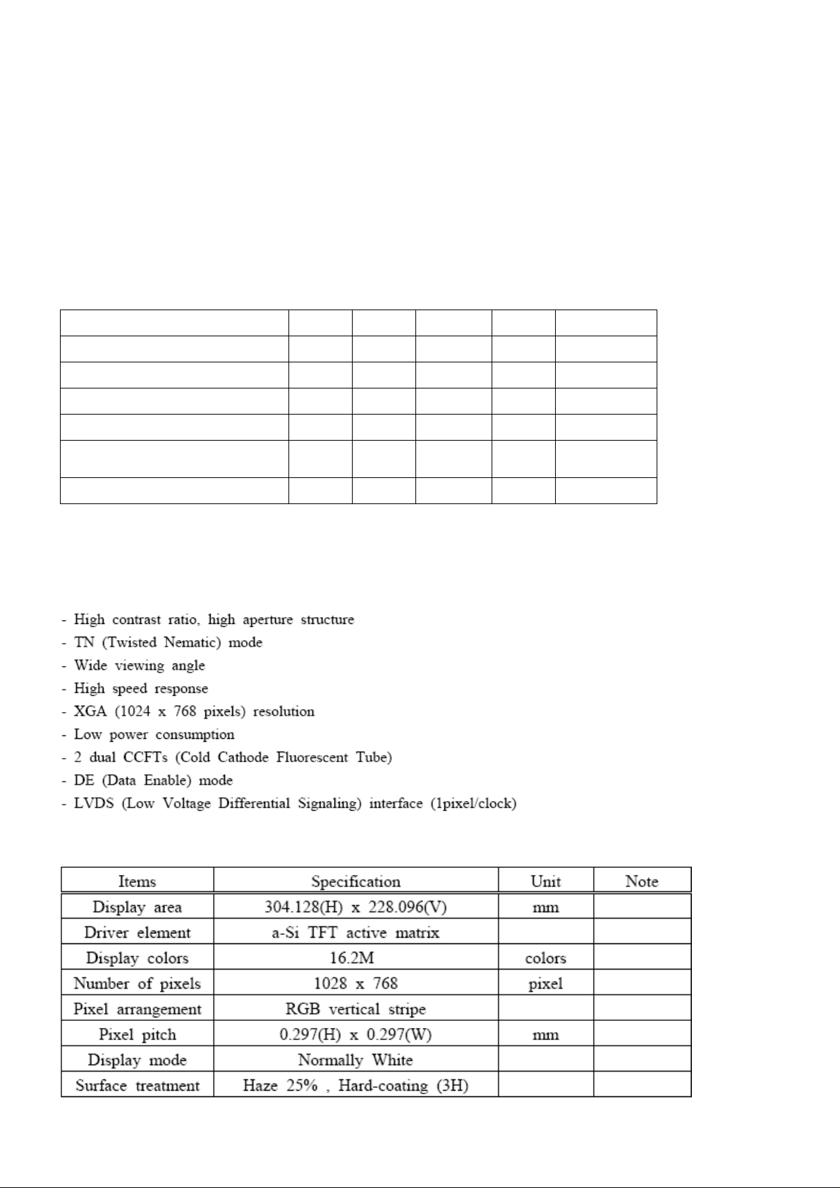
4.4.1 PANEL FEATURE
4.4.2 DISPLAY CHARACTERISTICS
11
DELL E152FPc
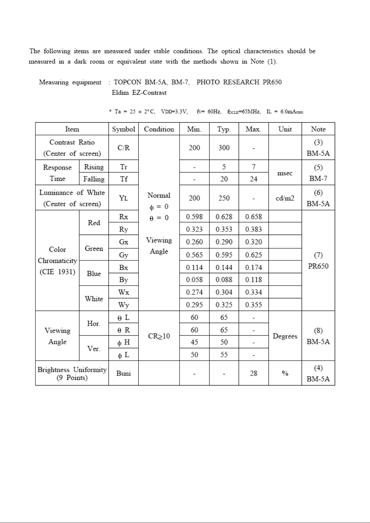
4.4.3 OPTICAL CHARACTERISTICS
12
DELL E152FPc
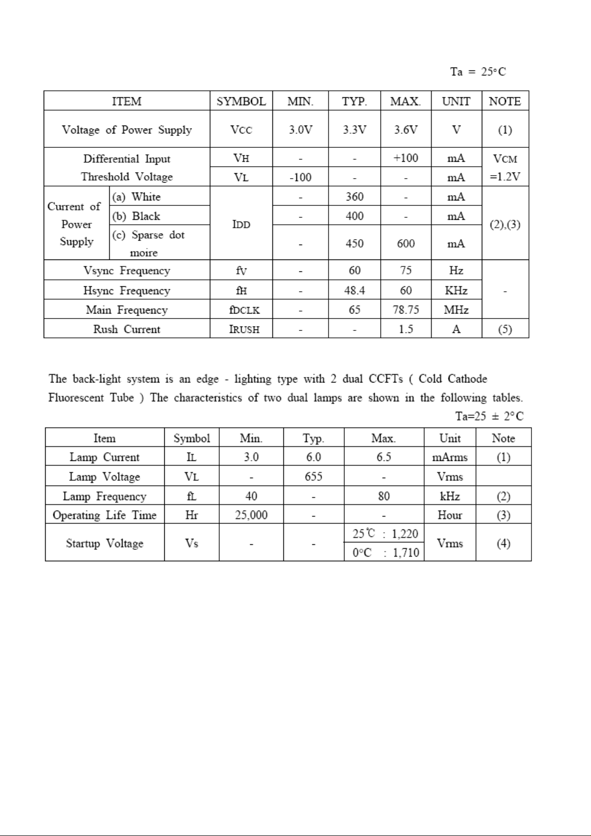
4.4.4 PARAMETER GUIDE LINE FOR CCFL INVERTER
BACKLIGHT
13
DELL E152FPc
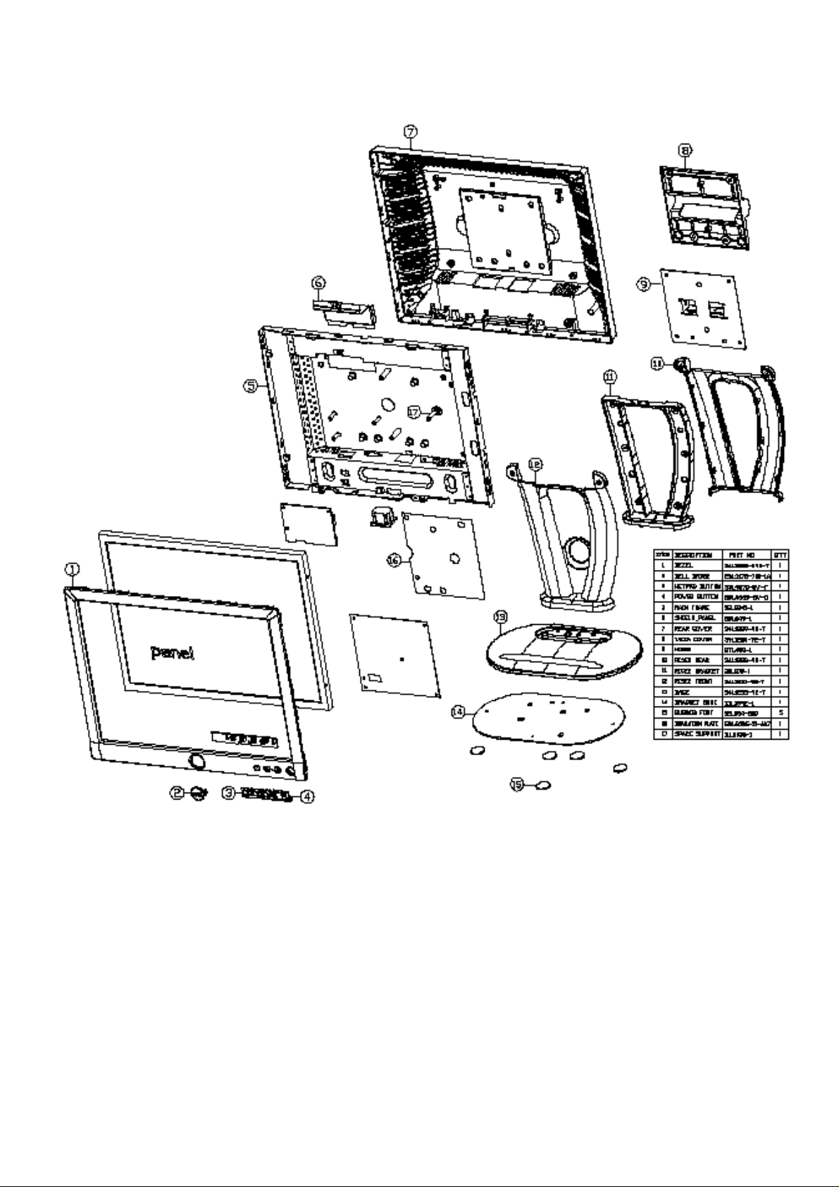
5. BLOCK DIAGRAM
5.1 MONITOR EXPLODED VIEW
14
DELL E152FPc
4
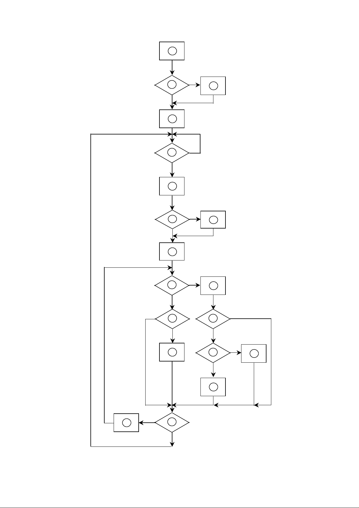
5.2 SOFTWARE FLOW CHART
1
2
Y
N
3
5
6
9
10
N
12
N
Y
N
7
Y
N
Y
11
13
8
N
18
Y
14
N
19
Y
15
17
Y
N
Y
16
15

DELL E152FPc
1) MCU Initializes.
2) Is the EEprom blank?
3) Program the EEprom by default values.
4) Get the PWM value of brightness from EEprom.
5) Is the power key pressed?
6) Clear all global flags.
7) Are the AUTO and SELECT keys pressed?
8) Enter factory mode.
9) Save the power key status into EEprom.
Turn on the LED and set it to green color.
Scalar initializes.
10) In standby mode?
11) Update the lifetime of back light.
12) Check the analog port, are there any signals coming?
13) Does the scalar send out an interrupt request?
14) Wake up the scalar.
15) Are there any signals coming from analog port?
16) Display "No connection Check Signal Cable" message. And go into standby mode after the message
disappears.
17) Program the scalar to be able to show the coming mode.
18) Process the OSD display.
19) Read the keyboard. Is the power key pressed?
16
DELL E152FPc
5.3 ELECTRICAL BLOCK DIAGRAM
Main Board
12MHz Crystal
MTV312MV
OSD
Control
Interface
(X200)
MCU
(U202)
TCLK/XTAL
EPR_SDA
EPR_SCL
EEPROM
M24C16
H-sync, V -sync
LCD Interface
(CN201)
Scalar GmZan3
(Include MCU, ADC, OSD)
(U200)
R/G/B
D-Sub
Connector
LVDS Signal output
(CN301)
(U201)
DB12_SDA,
DB15_SCL
(CN100)
EEPROM
24C02
(U100)
17
 Loading...