

Page 1
DX Object Storage Getting Started Guide
Version 5.0
Page 2

DX Object Storage Getting Started Guide: Version 5.0
Copyright © 2010 Caringo, Inc.
All Rights Reserved.
No part of this document may be reproduced, transmitted, or transcribed without the written consent of Caringo, Inc.
Page 3

Table of Contents
1. Welcome to DX Storage ...................................................................................................... 1
1.1. Components ............................................................................................................. 1
1.2. About this Document ................................................................................................. 1
1.2.1. Audience ....................................................................................................... 1
1.2.2. Scope ............................................................................................................ 1
2. Network Infrastructure and Recommendations ....................................................................... 2
2.1. About DX Storage in the Network .............................................................................. 2
2.1.1. Sample Networks ........................................................................................... 2
2.1.2. Layer 3 Switching and Routing ....................................................................... 4
2.1.3. Switching Hardware ........................................................................................ 4
2.1.4. Internet Deployments ...................................................................................... 6
2.2. Setting Up the Network for DX Storage ...................................................................... 6
2.2.1. Network Summary .......................................................................................... 7
2.2.2. Recommended Infrastructure .......................................................................... 7
2.3. Setting Up Network Services ..................................................................................... 7
2.3.1. Setting Up NTP for Time Synchronization ....................................................... 8
2.3.2. Setting Up DNS for Name Resolution .............................................................. 8
2.3.3. Preparing for Named Objects .......................................................................... 9
2.3.4. Setting Up SNMP for Monitoring ..................................................................... 9
2.3.5. Setting Up Network Load Balancing .............................................................. 10
2.4. Setting Up PXE Booting .......................................................................................... 10
2.4.1. Setting Up the DHCP Server for PXE Booting ................................................ 10
2.4.2. Configuring the TFTP Server ........................................................................ 11
2.5. Setting Up a Configuration File Server ..................................................................... 12
2.6. Network Devices and Priority ................................................................................... 13
2.7. Proxying the Admin Console .................................................................................... 14
2.8. IGMP Snooping Support .......................................................................................... 14
3. Hardware Considerations ................................................................................................... 15
3.1. Hardware Requirements and Recommendations ....................................................... 15
3.2. Hardware Setup ...................................................................................................... 15
3.3. About Memory Effects on Node Storage ................................................................... 15
3.4. Stream Size Guidance ............................................................................................ 16
3.5. Adaptive Power Conservation .................................................................................. 16
3.6. Proactive Power Conservation ................................................................................. 17
3.7. Local Area Replication Using Subclusters ................................................................. 17
4. Installing and Configuring DX Storage ................................................................................. 19
4.1. Licensing ................................................................................................................ 19
4.1.1. How Licensing Works ................................................................................... 19
4.1.2. About licenseFileURL ................................................................................... 20
4.1.3. About Licensed Capacity Monitoring .............................................................. 20
4.1.4. About Other Licensing Checks ...................................................................... 20
4.1.5. Sample License ............................................................................................ 21
4.2. Configuring DX Storage ........................................................................................... 21
4.2.1. Editing node.cfg ........................................................................................... 22
4.2.2. Storage Volume Configuration ....................................................................... 22
4.2.3. DHCP or Static Network ............................................................................... 23
4.2.4. Administration Password ............................................................................... 23
4.3. Booting DX Storage Nodes ...................................................................................... 23
4.4. Using Syslog ........................................................................................................... 24
5. Open Source Software ....................................................................................................... 25
Copyright © 2010 Caringo, Inc.
All rights reserved iii
Version 5.0
December 2010
Page 4

Chapter 1. Welcome to DX Storage
DX Storage is a high-performance, massively scalable, self-managing, cost-effective, fixed content
storage software that runs on clusters of standard x86 computer hardware. DX Storage provides the
integrity of an archive with the performance of primary storage.
1.1. Components
The DX Storage infrastructure is made up of the following components.
1. Cluster of x86 computers/nodes with one or more physical volumes running DX Storage software
2. Client applications that access the cluster through HTTP
3. TCP/IP network connecting cluster nodes and clients
1.2. About this Document
1.2.1. Audience
This document is intended for people in the following roles.
1. Storage system administrators
2. Network administrators
3. Technical architects
Throughout this document, the storage system administrator and network administrator roles will be
referred to as the administrator. The administrators are normally responsible for allocating storage,
managing capacity, monitoring storage system health, replacing malfunctioning hardware, and
adding additional capacity when needed. This document along with the application guide will be
valuable to technical architects in designing scalable, highly redundant, cost effective application
storage solutions.
1.2.2. Scope
This document covers the basic steps necessary to deploy and administer a DX Storage cluster.
The reader is expected to be familiar with TCP/IP networking and have a basic knowledge of x86
hardware setup. For additional configuration details and in-depth administration information, see the
DX Object Storage Administration Guide.
For information regarding DX Storage’s HTTP interface and application integration, see the DX
Object Storage Application Guide.
Copyright © 2010 Caringo, Inc.
All rights reserved 1
Version 5.0
December 2010
Page 5

Chapter 2. Network Infrastructure and
Recommendations
The following sections in this chapter discuss how to configure your network for DX Storage
clusters:
• Section 2.1, “About DX Storage in the Network”
• Section 2.2, “Setting Up the Network for DX Storage”
• Section 2.3, “Setting Up Network Services”
• Section 2.4, “Setting Up PXE Booting”
• Section 2.5, “Setting Up a Configuration File Server”
• Section 2.6, “Network Devices and Priority”
• Section 2.7, “Proxying the Admin Console”
• Section 2.8, “IGMP Snooping Support”
2.1. About DX Storage in the Network
The following topics in this section provide a high-level overview of setting up a DX Storage cluster
in your network:
• Section 2.1.1, “Sample Networks”
• Section 2.1.2, “Layer 3 Switching and Routing”
• Section 2.1.3, “Switching Hardware”
• Section 2.1.4, “Internet Deployments”
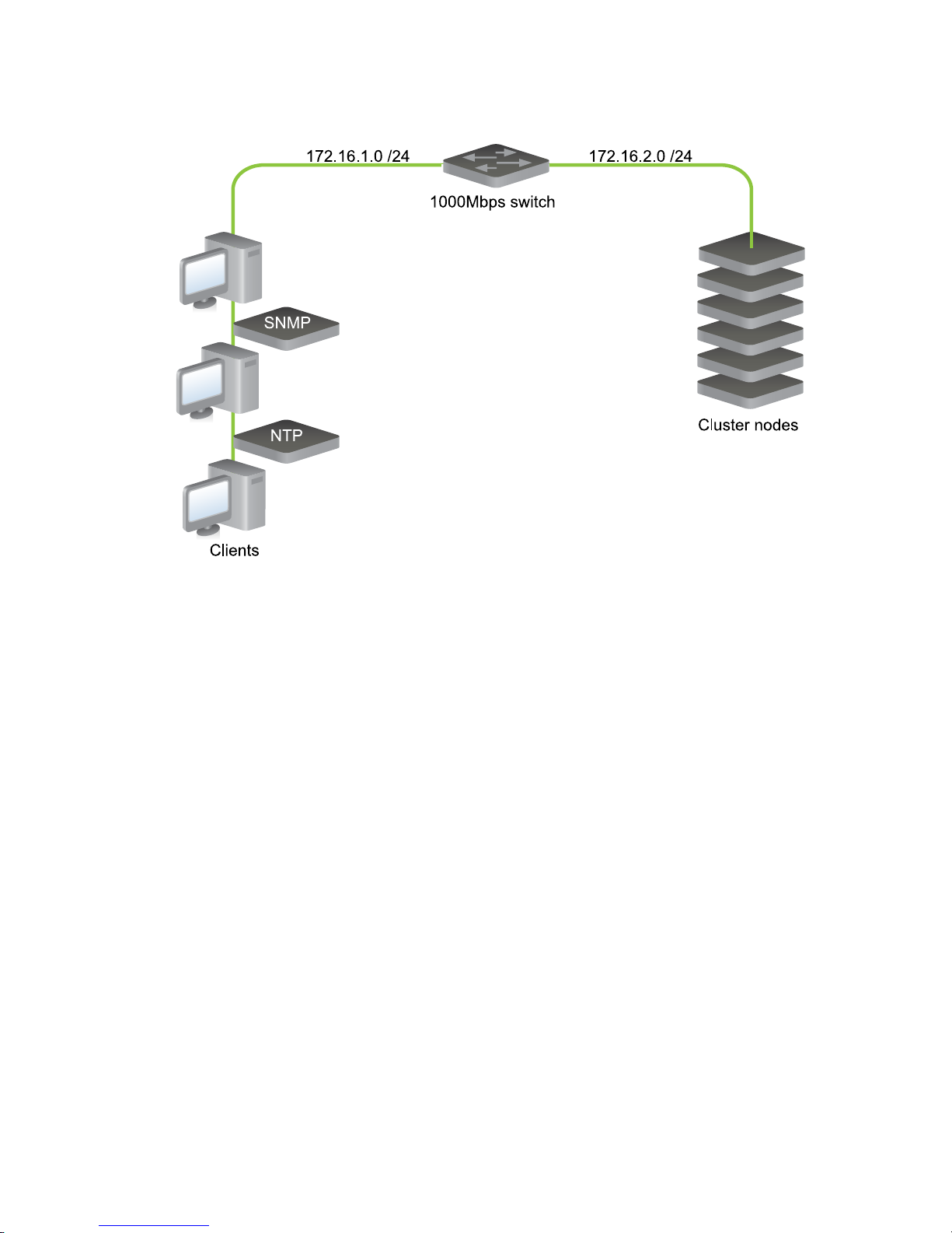
2.1.1. Sample Networks
The following figure shows a basic network where the DX Storage cluster nodes, the clients, and
the servers are all in the same subnet. While this is the easiest to setup and requires only basic
hardware, it does not offer any traffic separation between the DX Storage nodes and the rest of the
network.
Copyright © 2010 Caringo, Inc.
All rights reserved 2
Version 5.0
December 2010
Page 6
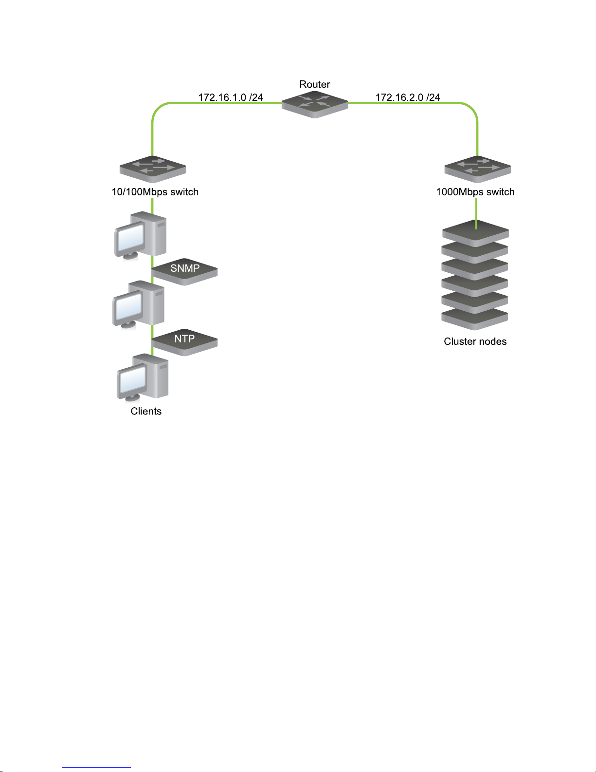
The next figure shows a more sophisticated network topology that uses a router to separate traffic
between the DX Storage nodes and the rest of the network.
Copyright © 2010 Caringo, Inc.
All rights reserved 3
Version 5.0
December 2010
Page 7
2.1.2. Layer 3 Switching and Routing
A router or a layer 3 switch routes network packets between subnets. A router segregates network
traffic by filtering packets based on the subnet to which they are addressed. This segregation is
important so that DX Storage nodes have predicable network bandwidth for their use and so that
their multicast and unicast traffic doesn’t interfere with computers on the rest of the network.
2.1.3. Switching Hardware
When selecting Ethernet switching hardware, consider that many client workstations have 100Mbps
network interfaces and it might not be cost effective to connect these workstations to Gigabit ports.
Additionally, the operating systems and applications running on these workstations might be unable
to effectively utilize more than 100Mbps of bandwidth.
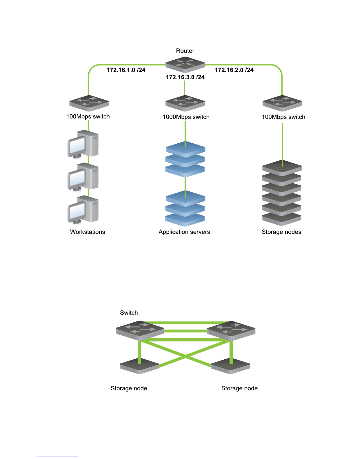
The following figure shows a network architecture where workstations, enterprise servers, and DX
Storage nodes are isolated on appropriately sized switches.
Copyright © 2010 Caringo, Inc.
All rights reserved 4
Version 5.0
December 2010
Page 8
With more sophisticated switching hardware, the network segments can be isolated as different
Virtual LANs (VLANs) on the same device. Additionally, some enterprise-class switching hardware
has routing capabilities.
You can also design the DX Storage subnet to use redundant switches in the event of a switch
failure. The following figure shows an example of DX Storage nodes connected to multiple network
switches. In the event any single component becomes unavailable, a redundant path is available so
communication is uninterrupted.
When deploying DX Storage with multiple switches, the interconnection between the switches
requires planning. To allow for full speed communications between active ports on different
Copyright © 2010 Caringo, Inc.
All rights reserved 5
Version 5.0
December 2010
Page 9
switches, the network connection between switches must be faster than the individual ports. Contact
your switch provider for information about proprietary software or use a mechanism such as link
aggregation.
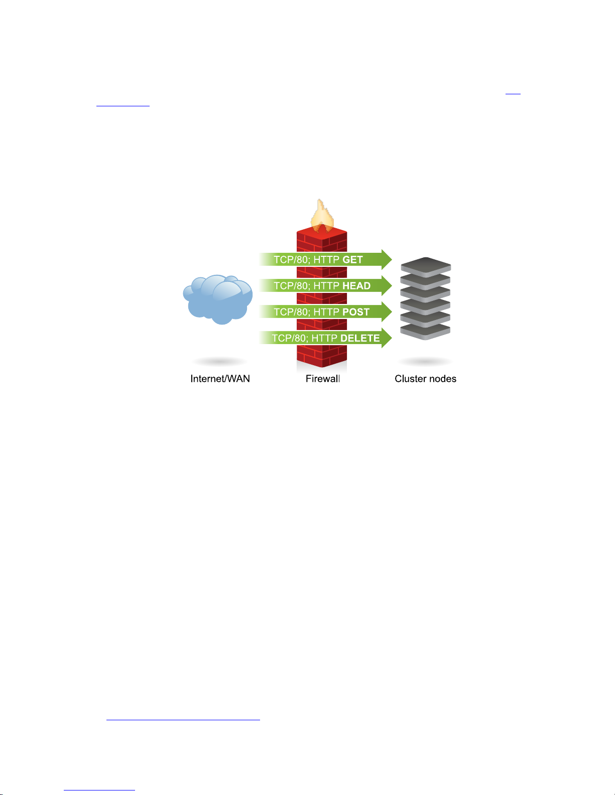
2.1.4. Internet Deployments
Network security is one of the top considerations during the deployment of any service on the
Internet or within an extensive enterprise WAN. In these types of deployments, put a firewall or
filtering router in front of DX Storage to control the kind of traffic and requests that are allowed to
reach the cluster nodes.
The preceding figure shows a firewall that allows requests on TCP/80. This is the default SCSP port,
but it should be changed to match the scspport value set in the node or cluster configuration file for
the DX Storage cluster if it is something other than 80.
If the firewall is sophisticated enough to examine Layer 7 (Application Layer), or the contents of
the HTTP requests, further restrictions should be made to allow only GET, HEAD, POST, DELETE
requests. If a cluster is exposed read-only to these external clients, the POST and DELETE
requests can be blocked to prevent updates to the cluster. To prevent client access to the node
status page, the firewall should deny “GET /” requests to the cluster nodes.
Administrators should block Internet access to the Admin Console port (default TCP/90) and to
the SNMP port (UDP/161). In wide-area networks, further restrictions might be desirable to restrict
access to these services to specific administrative networks or workstations.
Anytime critical devices such as firewalls are introduced into a network architecture, they should be
deployed in redundant pairs to minimize the chance of failures that cut-off all client access.
2.2. Setting Up the Network for DX Storage
Client applications must be able to initiate TCP connections with all nodes in a DX Storage cluster
using the designated access port, typically port 80. Internally, DX Storage nodes must be able to
communicate with each other using UDP, TCP, and multicast.
The following topics in this section discuss how to set up a DX Storage cluster in a standard TCP/IP
networking environment:
• Section 2.2.1, “Network Summary”
Copyright © 2010 Caringo, Inc.
All rights reserved 6
Version 5.0
December 2010
Page 10

• Section 2.2.2, “Recommended Infrastructure”
2.2.1. Network Summary
The following table summarizes all required or optional network interfaces utilized by DX Storage:
Interface Type Required/Optional
SCSP TCP/80 Required
Admin Console TCP/90 Optional but Recommended
DHCP UDP/67 Optional but Recommended
DNS UDP/53 Optional
NTP UDP/123 Required
Logging UDP/514 Optional but Recommended
SNMP UDP/161 Optional but Recommended
mDNS UDP/5353 Optional
TFTP UDP/69 Optional
2.2.2. Recommended Infrastructure
The following networking services are recommended for the management of a DX Storage cluster.
• DHCP server for allocating node addresses
• NTP time server to provide clock synchronization. Dell recommends you configure multiple
NTP servers (or multiple pools of servers) that are located in the proximity of your cluster. Clock
synchronization is critical for many of DX Storage's components.
For example, you can use the NTP Pool Project's continental zones, which are pools of NTP
servers.
For more information, see Section 2.3.1, “Setting Up NTP for Time Synchronization ”.
• Syslog server for receiving critical alerts
Gigabit Ethernet is the recommended connection speed between DX Storage cluster nodes.
DX Storage automatically makes use of multiple network interfaces to provide a redundant network
connection. To use this feature, connect the network interfaces to the one or more interconnected
switches in the same subnet. See Section 2.1.3, “Switching Hardware” for more information.
2.3. Setting Up Network Services
The following topics discuss how to set up network services for your DX Storage cluster:
• Section 2.3.1, “Setting Up NTP for Time Synchronization ”
• Section 2.3.2, “Setting Up DNS for Name Resolution”
• Section 2.3.3, “Preparing for Named Objects”
• Section 2.3.4, “Setting Up SNMP for Monitoring”
• Section 2.3.5, “Setting Up Network Load Balancing”
Copyright © 2010 Caringo, Inc.
All rights reserved 7
Version 5.0
December 2010
Page 11

2.3.1. Setting Up NTP for Time Synchronization
DX Storage clusters are capable of synchronizing their nodes’ clocks internally. However, Dell
strongly recommends you use one or more trusted network time protocol (NTP) servers whenever
they are available. This assures that a cluster’s clock is in sync with the clocks of the client
machines. If you boot DX Storage from a CSN, the CSN provides NTP services for all DX Storage
nodes and no further configuration is required.
If one or more trusted NTP servers are available, configure DX Storage to use them by setting the
timeSource parameter in the node or cluster configuration files. The value of the timeSource
parameter is a list of one or more NTP servers separated by spaces. An example follows:
timeSource = 10.20.40.21 10.20.50.31
If your DX Storage nodes are able to resolve host names, you can use NTP pool servers. Dell
recommends you use pool servers that are close to your servers' time zone as discussed on the
ntp.org help page. (To view the page in a language other than English, start with www.ntp.org and
click the "how do I use?" link.)
The following example shows how to use United States-based NTP servers:
timeSource = 0.us.pool.ntp.org 1.us.pool.ntp.org 2.us.pool.ntp.org
Note
NTP version 3 has design limitation that causes time to wrap in the year 2036. If a
computer's BIOS clock is set beyond this wrap point, NTP cannot correct the time. Make
sure that all BIOS clocks are set to a date prior to 2036 before booting DX Storage.
Alternatively, you can use NTP version 4.
2.3.2. Setting Up DNS for Name Resolution
The domain name service (DNS) is used to resolve host names into IP addresses. While DNS is
not required for DX Storage nodes to communicate with each other, DNS can be very useful for
client applications to reach the cluster. If you use named objects, DNS is one method you can use to
enable access to objects over the Internet.
Although client applications can initiate first contact with any node in the DX Storage cluster – even
choosing to access the same node every time - Dell recommends that the node of first contact be
evenly distributed around the cluster.
Basic options follow:
• Define multiple DNS entries ("A" or "CNAME" records) that each specify the IP address of the
same DX Storage node of first contact.
• Use multiple IP addresses for a DNS entry to create a DNS round-robin which provides client
request balancing.
Consult your DNS software documentation for guidance on using "A" records and "CNAME" (alias)
records.
The following example shows the entries for three node IP addresses tied to one name. This is the
configuration file format of the widely used ISC Bind Daemon.
DX Storage 0 IN A 192.168.1.101
0 IN A 192.168.1.102
Copyright © 2010 Caringo, Inc.
All rights reserved 8
Version 5.0
December 2010
Page 12

0 IN A 192.168.1.103
In the preceding example, it is important that the time to live (TTL) value for each of the records in
the round-robin group is very small (0-2 seconds). This is necessary so that clients that cache the
resolution results will quickly flush them. This allows for the distribution of the node of first contact
and allows a client to quickly move on to another node if it tries to contact a failed node.
Although it is recommended that applications implement more robust mechanisms like zeroconf
for distributing the node of first contact and skipping failed nodes, an administrator can use DNS to
assist with less sophisticated applications.
2.3.3. Preparing for Named Objects
For users to be able to access named objects over the Internet, you must enable incoming HTTP
requests to resolve to the correct domain. (A cluster can contain many domains, each of which can
contain many buckets, each of which can contain many named objects.) Cluster and domain names
should both be IANA-compatible host names like cluster.example.com and are discussed in
more detail in the DX Object Storage Administration Guide.
For example, a client application can create an object with a name like the following:
cluster.example.com/marketing/photos/ads/object-naming.3gp
In this example, cluster.example.com is the domain name, marketing is the name of a
bucket, and photos/ads/object-naming.3gp is the name of an object. You must set up your
network so the host name in the HTTP request maps correctly to the object's domain name. (The
cluster name is not important in this regard.)
To enable users to access the preceding object, you must set up one of the following:
• Set up your hosts file to map domain names to IP address(es) of the node of first contact.
For a Linux system, configure /etc/hosts
For a Windows system, configure %SystemRoot%\system32\drivers\etc\hosts
A sample hosts file follows:
192.168.1.111 cluster.example.com
192.168.1.112 vault.example.com
• Define multiple DNS entries (that is, "A" or "CNAME" records) that specify the IP address(es) of
the DX Storage node of first contact.
Specifying multiple IP addresses for a DNS entry creates a DNS round-robin which provides client
request balancing.
For more information about setting up DNS for DX Storage, see Section 2.3.2, “Setting Up DNS
for Name Resolution”.
For details about setting up your DNS server, consult your DNS software documentation.
2.3.4. Setting Up SNMP for Monitoring
DX Storage exposes monitoring information and administrative controls through SNMP. An SNMP
console provides an administrator a mechanism with which to monitor a DX Storage cluster from
a central location. See the SNMP appendix in the DX Object Storage Administration Guide for
additional information. The SNMP MIB definition file for DX Storage is located as follows:
Copyright © 2010 Caringo, Inc.
All rights reserved 9
Version 5.0
December 2010
Page 13

• If you boot from a CSN, an aggregate MIB for the entire cluster is available in /usr/share/
snmp/mibs.
• If you do not boot from a CSN, the MIB is located in the root directory of the DX Storage software
distribution.
2.3.5. Setting Up Network Load Balancing
Although the DX Storage nodes interact with client applications using the HTTP communication
protocol, the nodes are not simple web servers and they have operation behaviors that are different
from traditional web servers. For these reasons, the placement of DX Storage nodes behind an
HTTP load balancer device is not a supported configuration.
During normal operations, a DX Storage node routinely redirects a client to another node within the
cluster. When this happens, the client must be able to make another HTTP request directly to the
node to which they were redirected. Any mechanism that virtualizes the IP addresses of the DX
Storage nodes or tries to control the nodes to which a client connects will interfere with DX Storage
and will create communication errors.
2.4. Setting Up PXE Booting
This section discusses how to boot a cluster from the network using Intel’s Preboot Execution
Environment (PXE) specification. This is commonly referred to as “network booting” and is
supported by most modern network adapters.
Note
If you boot from a CSN, you can skip this section because PXE booting is already
enabled.
PXE is one way to boot DX Storage nodes. You can also boot nodes from a USB flash drive as
discussed in Section 4.2, “Configuring DX Storage” or using a configuration file server as discussed
in Section 2.5, “Setting Up a Configuration File Server”.
To enable a cluster node to PXE boot, you must configure a DHCP server and a TFTP server to
support network booting.
Warning
DX Storage can erase all non-DX Storage data on hosts that are accidentally booted from
the network. When you set up your DHCP server, make sure it provides network booting
information to the correct network hosts only.
Following are the high-level tasks required to set up PXE booting:
1. Configure your DHCP server with next-server and filename parameters.
2. Configure the TFTP server with PXE bootstrap, configuration, and DX Storage files.
3. Set up the nodes’ BIOS configurations for network booting.
2.4.1. Setting Up the DHCP Server for PXE Booting
The following example shows the configuration lines from the Internet Systems Consortium (ISC)
DHCP server that is commonly available on UNIX systems. It shows the use of the next-server
Copyright © 2010 Caringo, Inc.
All rights reserved 10
Version 5.0
December 2010
Page 14

parameter to define the IP address of the TFTP server and the filename parameter to define the
bootstrap loader program to download.
group {
next-server 172.16.1.10;
filename "/pxelinux.0";
# Hosts allowed to network boot into DX Storage
host clusternode1 { hardware ethernet 00:90:cb:bf:45:26; }
host clusternode2 { hardware ethernet 00:90:b2:92:09:e4; }
host clusternode3 { hardware ethernet 00:90:0d:46:7a:b4; }
}
In the preceding DHCP configuration file example, the DX Storage nodes are explicitly defined by
MAC address to prevent the unintended booting of DX Storage by other servers or workstations.
2.4.2. Configuring the TFTP Server
In addition to the DHCP, you must configure a TFTP server from which to load the DX Storage
software. The following steps are necessary to setup a TFTP boot server.
1. Install and configure TFTP server software on the boot server.
2. Create the /tftpboot directory hierarchy.
3. Copy the kernel and fsimage files to the /tftpboot/profiles/castor directory.
You should also review the information discussed in Section 2.4.2.4, “DHCP and Boot Server
Redundancy”.
2.4.2.1. Installing and Configuring TFTP
There are many free and commercially available packages that provide a TFTP server and UNIX
distributions commonly include this in their standard setup. For example, the tftp-hpa package for
UNIX is known to work with DX Storage.You can get source code from http://www.kernel.org/pub/
software/network/tftp/ and it is also available as a binary package in many Linux distributions.
2.4.2.2. Creating the tftpboot Directory Hierarchy
After installing the TFTP server, you must configure it to serve the directory where the network boot
files are located. This directory is typically /tftpboot because TFTP is almost exclusively used for
booting network devices. A sample template of this directory is included in the DX Storage software
distribution in the samples/Network-Boot directory.
2.4.2.3. Copying kernel and fsimage
The DX Storage software distribution media contains files named kernel and fsimage that you
must copy to the tftpboot/profiles/castor directory on the TFTP server. These files contain
the DX Storage embedded operating system and will be loaded at boot time by every DX Storage
storage node.
After copying the directory template and the DX Storage software files, the tftpboot directory on
the TFTP server should contain the following files.
File name Description
tftpboot/pxelinux.0 Boot loader program
Copyright © 2010 Caringo, Inc.
All rights reserved 11
Version 5.0
December 2010
Page 15

File name Description
tftpboot/profiles/castor/fsimage DX Storage software
tftpboot/profiles/castor/kernel DX Storage operating system kernel
tftpboot/pxelinux.cfg/default PXELINUX configuration file
For additional information regarding the use of the PXELINUX boot loader, refer to the included
documentation and ZIP file in the samples/Network-Boot directory on the DX Storage
distribution media.
2.4.2.4. DHCP and Boot Server Redundancy
To eliminate a single point of failure if your DHCP server goes offline, you must configure both
primary and secondary DHCP servers. Details on the necessary steps to set up the ISC DHCP
daemon for redundancy can be found in the following article: http://www.madboa.com/geek/dhcp-
failover/
To provide redundancy at the network booting layer, your primary and secondary DHCP servers can
be used as TFTP servers as well. In their setups, set the next-server parameter specify to their
own IP address. This way, whichever DHCP server answers the DHCP query will also be the server
that handles the PXE boot. To prevent any network interruptions, the TFTP boot server(s) should
be on the same broadcast domain (that is, VLAN) as the DX Storage nodes, or you should enable a
DHCP relay server on the VLAN.
2.5. Setting Up a Configuration File Server
Note
If you boot from a CSN, the tasks discussed in this section are not necessary or
recommended. Your system is already set up to PXE boot from the CSN.
DX Storage supports centralizing the node configuration files on an HTTP or FTP server. This
method of booting can be used with network booting or with standard USB flash drive booting.
A centralized configuration server simplifies the administration of large DX Storage clusters by
allowing configuration file updates and by providing a method to group configurations of similar
nodes.
To use a configuration file server, set the value of the castor_cfg kernel configuration parameter
to a URL that specifies the configuration list file. For details, see one of the following examples:
• PXE boot example.
Following is an example PXELINUX configuration file from the tftpboot/pxelinux.cfg
directory on the TFTP boot server.
default profiles/castor/kernel
append initrd=profiles/castor/fsimage
ramdisk_size=128000 root=/dev/ram0
castor_cfg=http://172.16.1.200/castor/cfg-list.txt
Note
The append command must be entered on a single line. It is shown here on multiple
lines because of space limitations.
Copyright © 2010 Caringo, Inc.
All rights reserved 12
Version 5.0
December 2010
Page 16

• USB boot loader example.
Following is an example section of the syslinux.cfg that is contained in the root directory on
the USB flash drive.
label normal
kernel kernel
append initrd=fsimage ramdisk_size=128000 root=/dev/ram0
castor_cfg=http://172.16.1.200/castor/cfg-list.txt
Note
The append command must be entered on a single line. It is shown here on multiple
lines because of space limitations.
• Configuration list file example.
The castor_cfg kernel configuration parameter specifies a file that contains a list of URLs for all
the configuration files that are to be loaded by a DX Storage node. DX Storage configuration files
are evaluated in the order in which they are listed in the configuration list file.
Although DX Storage configuration parameters can be defined multiple times, the last definition is
the only one used. Using redefinitions of parameters, you can layer configuration files so that they
contain generally applicable values for a cluster, a group of similar nodes, and values specific to
one node.
An example configuration list file follows:
http://172.16.1.200/castor/cluster.cfg
http://172.16.1.200/castor/subcluster.cfg
http://172.16.1.200/castor/testnode.cfg
Each of the configuration files in the list file uses the same format as the DX Storage node.cfg
file. See the /caringo/node.cfg.sample in the DX Storage software distribution. For more
information about configuration parameters, see the DX Object Storage Administration Guide.
2.6. Network Devices and Priority
By default, all DX Storage Ethernet network adapters are encapsulated into a redundant bond
interface where one device is active and the others are backups. In this default mode, the first
network device is the preferred one. You can override this behavior in the following situations:
• Network adapter, such as an IPMI card, must be excluded from use
• Preferred network adapter change for network load management
• Bonding of multiple adapters for increased throughput
First, you might need to configure the ports on the switch for the appropriate mode as required by
that mode; these are normally link-aggregation or 802.3ad. DX Storage supports all Linux bonding
driver supported modes.
To override DX Storage’s default handling of the network devices, you must edit one of the following
boot configuration files:
• syslinux.cfg if the node is booting from the USB flash drive
Copyright © 2010 Caringo, Inc.
All rights reserved 13
Version 5.0
December 2010
Page 17

• pxelinux.cfg if the node is booting from the network
In the configuration file, a kernel parameter named castor_net is included in the append clause.
castor_net enables you to specify both the bonding mode for the adapters as well as a commaseparated ordered list of the network devices that DX Storage can use, where the first device in the
list is the preferred interface that will be used whenever it is on-line.
The list of network devices must utilize the adapter names assigned by DX Storage. To find the
current list of adapter names and MAC addresses, hold down the Shift key while booting a node and
enter utility at the prompt.
DX Storage assigns device names to adapters based on a sorted list of MAC addresses. Device
names begin with eth followed by an integer starting at 0. Adding network hardware can change the
assignment order.
Some examples follow. The other portions of the append clause have been abbreviated for clarity.
Note the trailing colon after the bonding mode:
append initrd=... castor_net=active-backup:eth1,eth0
append initrd=... castor_net=balance-rr:eth0,eth1
append initrd=... castor_net=802.3ad:eth1,eth0
append initrd=... castor_net=eth1,eth2
append initrd=... castor_net=802.3ad:
2.7. Proxying the Admin Console
Administrators running DX Storage on a private, protected network may wish to allow clients on
the external network to view the DX Storage console without also providing them access to the
nodes themselves on the private network. This can by accomplished by proxying the console from
a privileged server that straddles the internal and external networks. For instance, from a server
running Apache, the following rewrite rule for URLs could be applied via the mod_rewrite module:
<Location /storage/>
RewriteEngine On
RewriteRule
^.*/storage/([^/]+)/(.*)$
http://$1:90/$2 [P,L]
</Location>
Please reference the Apache documentation for mod_rewrite for full details.
2.8. IGMP Snooping Support
Managed switches commonly make use of IGMP snooping in order to direct multicast traffic to
their ports. By default, DX Storage uses IGMPv2 responses to host membership queries. The
igmpVersion parameter can be used to force the use of version 1, 2, or 3.
Copyright © 2010 Caringo, Inc.
All rights reserved 14
Version 5.0
December 2010
Page 18

Chapter 3. Hardware Considerations
The following sections in this chapter discuss how to configure your network for DX Storage
clusters:
• Section 3.1, “Hardware Requirements and Recommendations”
• Section 3.2, “Hardware Setup”
• Section 3.3, “About Memory Effects on Node Storage”
• Section 3.4, “Stream Size Guidance”
• Section 3.5, “Adaptive Power Conservation”
• Section 3.6, “Proactive Power Conservation”
• Section 3.7, “Local Area Replication Using Subclusters”
3.1. Hardware Requirements and Recommendations
DX Storage installs and runs on enterprise-class x86 commodity hardware. To ensure adequate
coverage in the event of a node failure, the minimum recommended number of nodes in the cluster
is 3. For a complete overview of hardware minimums and recommendations, please reference the
hardware documentation included with your software.
3.2. Hardware Setup
The DX Storage node hardware should be configured to boot either from the USB flash drive or to
PXE network boot (which is the default if using a Cluster Services Node). See Section 2.4, “Setting
Up PXE Booting” for more information about setting up PXE booting.
If your cluster boots from a CSN, you can ignore this section because hardware setup is already
done for you.
When USB booting, the USB device might be identified as a hard drive on some hardware while on
others it is identified as a removable device. It should be moved to the top of the boot priority order
so that the system will boot from the USB flash drive before any other boot devices in the node.
Because all internal disks are typically used for cluster storage, BIOS might prevent you from
booting to a hard drive. You should check to make sure that the boot priority of these is lower than
that of the USB flash drive.
Because it is not necessary to have a keyboard attached during normal operations of DX Storage, it
might be necessary to configure the node’s BIOS to ignore keyboard errors during boot.
3.3. About Memory Effects on Node Storage
The DX Storage cluster is capable of holding the sum of the maximum stream counts from all nodes
in the cluster. The number of individual streams that can be stored on a DX Storage node depends
both on its disk capacity and the amount of system RAM. The following table shows an estimate of
the maximum possible number of streams, regardless of size, you can store on a node based on the
amount of RAM in the node.
Copyright © 2010 Caringo, Inc.
All rights reserved 15
Version 5.0
December 2010
Page 19

Amount of RAM Maximum number of immutable
unnamed streams
Maximum number of unnamed
anchor streams or named
streams
4GB 33 million 16 million
8GB 66 million 33 million
12GB 132 million 66 million
3.4. Stream Size Guidance
This section provides guidelines you can use to size storage volumes for large stream sizes. The
largest object a DX Storage cluster can store is one-fifth the size of the largest volume in the cluster.
If you attempt to store a larger object, DX Storage logs an error and does not store the object.
To further tune your hardware planning, keep in mind that the DX Storage health processor reserves
defragmentation space on a volume equal to twice the size of the largest stream that has been
stored on a volume. Therefore, you might end up having much lower storage capacity than you
expect.
If possible, size your hardware so that the largest streams consume between 10 and 20 percent
of available space on disk drives used in the storage cluster. If the largest stream consumes 10 to
20 percent of disk drive space, you get 60% utilization of available space. The percent utilization
improves as you add more disk space.
For example, if the largest stream consumes between 5 and 10% of disk space, utilization improves
to 80%. If the largest stream consumes only 1.25 to 2.5% of available disk space, utilization is 95%.
If disk utilization is diminishing, you should consider upgrading the size of the disk drives in your
cluster nodes.
3.5. Adaptive Power Conservation
As of the 4.0 release, DX Storage includes an adaptive power conservation feature that
supplements DX Storage's naturally green characteristics to spin down disks and reduce CPU
utilization after a configurable period of inactivity. A cluster that is constantly in use will likely not
benefit significantly from the adaptive power feature but a cluster that has long periods of inactivity
on nights and weekends can expect significant power savings utilizing this feature. Because only
inactive nodes are affected, max available throughput will not be affected, though additional latency
will be incurred on the first access to a sleeping node. The cluster will automatically awake one
or more nodes to carry out requests when needed and eventually revive all nodes if needed. The
configuration parameters that control the adaptive power conservation features can all be set in the
node and/or cluster configuration files.
If a node has not serviced any incoming SCSP requests (both client and internode) in the last
configurable sleepAfter seconds, it will change to an idle status and pause its health processor,
allowing the associated disks to eventually turn idle as well after they have had no IO activity
in the past sleepAfter seconds. When an application or another node in the cluster once again
begins sending SCSP requests, one or more of the nodes in the cluster will awake to service those
requests. Even if no outside activity is detected for a long period, each node will awake after it has
been idle for the configurable wakeAfter seconds so that the health processor can monitor disk and
content integrity.
In addition to the sleepAfter and wakeAfter parameters, a new archiveMode setting allows an
administrator to designate a new or empty node as an archive node that will remain idle in lowpower mode without participating in cluster activity until its capacity is needed. This allows
administrators to have additional capacity online and available without paying for the associated
Copyright © 2010 Caringo, Inc.
All rights reserved 16
Version 5.0
December 2010
Page 20

power costs of the additional nodes. For more information about sleepAfter, wakeAfter,
and archiveMode settings, see the node configuration appendix in the DX Object Storage
Administration Guide.
3.6. Proactive Power Conservation
In addition to the power savings gained from the adaptive power conservation feature,
administrators may need the ability to proactively reduce the power consumption peak and flatten
the power spectrum consumption of the grid where power caps are required for either budgetary
or compliance reasons. To support this use case, DX Storage allows administrators to optionally
set the power cap for the cluster to a percentage of the maximum potential power consumption via
either the admin console Settings pop-up or SNMP. It is highly likely that the power cap mode will
result in some performance degradation so administrators should be aware of the potential impact to
throughput prior to setting the power cap to anything lower than 100%. Note this feature is currently
supported only on select Dell hardware.
Note
If the power cap percentage is changed using SNMP or the Admin Console and the
corresponding cluster settings UUID is not updated in DX Storage configuration, the
admin console and SNMP may get out of sync with the actual node state, as the power
cap is preserved across reboots even if the cluster settings UUID is not persisted.
3.7. Local Area Replication Using Subclusters
Local area replication (LAR) allows you to create logical separations in a DX Storage cluster to
define storage distribution strategies. These logical separations change the normal behavior of
the cluster so that DX Storage attempts to create the greatest logical spread between a stream’s
replicas by moving them into separate subclusters. If your cluster boots from a CSN, contact your
support representative for instructions on manually configuring subclusters because the CSN
Console does not currently support this.
Examples where LAR subclusters are useful:
• Splitting a cluster based on location (data cabinet, building wing)
• Grouping nodes based on common infrastructure (network, power)
An example of splitting a cluster based on location is a company that has data centers in separate
wings of their building and wishes to have copies of stored content exist in both wings in case of a
partial building loss. A loss could be events like a fire, flooding, or air conditioning problems.
Similar to location based separation, you might wish to split a cluster based on common
infrastructure. Examples are grouping nodes by shared network switches, a common Power
Distribution Unit (PDU), or a common electrical circuit with in a rack.
The network connections between LAR subclusters must have the same speed and latency
characteristics as the connections between the nodes. Additionally, all nodes must be in the same
broadcast domain such that they are able to send data directly to all other nodes in the cluster and
receive the multicast traffic sent from anywhere in the cluster.
Warning
Avoid frequent changes to the subcluster assignments for nodes. When nodes move
to new subclusters, there is the potential for a lot of cluster activity while content is
redistributed to account for the new subcluster assignments.
Copyright © 2010 Caringo, Inc.
All rights reserved 17
Version 5.0
December 2010
Page 21

When you retire a volume, you must make sure that sufficient space exists in the LAR subcluster
that contains the retiring volumes if you want the separation to persist. Because DX Storage must
maintain the correct number of replicas in the subcluster, retiring a volume without sufficient space
can be problematic. For example, DX Storage might create all replicas on the other side of the
subcluster, and might ultimately result in filling up that side of the subcluster.
Copyright © 2010 Caringo, Inc.
All rights reserved 18
Version 5.0
December 2010
Page 22

Chapter 4. Installing and Configuring DX Storage
This chapter discusses how to set up and configure a basic DX Storage cluster.
Note
If you boot DX Storage from a Cluster Services Node (CSN), the required infrastructure
setup, installation and configuration updates are performed automatically as part of CSN
configuration so the tasks discussed in this chapter are not necessary or recommended.
This chapter discusses the following topics:
• Section 4.1, “Licensing”
• Section 4.2, “Configuring DX Storage”
• Section 4.3, “Booting DX Storage Nodes”
• Section 4.4, “Using Syslog”
4.1. Licensing
You receive a DX Storage license for the contractually agreed amount of storage space for a given
cluster or a license is generated from the published aggregate of multiple capacity keys from the
CSN Console. The location of your license file is specified by the licenseFileURL parameter in
your node or cluster configuration file.
See one of the following sections for more information about licensing:
• Section 4.1.1, “How Licensing Works”
• Section 4.1.2, “About licenseFileURL”
• Section 4.1.4, “About Other Licensing Checks”
• Section 4.1.5, “Sample License”
4.1.1. How Licensing Works
DX Storage uses the following logic to determine your licensing:
1. The default license is 2TB per cluster.
2. DX Storage attempts to read the license file from the location specified by licenseFileURL.
3. If a valid license is found, DX Storage uses it.
If the file specified by licenseFileURL is not a valid license, the storage capacity is set at 0.
4. If DX Storage fails to read the license specified by licenseFileURL (for example, the file is on
a web server that is temporarily unavailable), DX Storage uses the last valid license.
Licensing troubleshooting suggestions:
• If the capacity of a node in your cluster is 0, make sure the license specified by
licenseFileURL is a valid DX Storage license. In particular, make sure no one has manually
edited the license because doing so invalidates the license key.
Copyright © 2010 Caringo, Inc.
All rights reserved 19
Version 5.0
December 2010
Page 23

• If the capacity of a node in your cluster is set to the default of 2TB for an extended period of time,
verify all of the following:
• You have a valid DX Storage license.
• You set the licenseFileURL to the location of the license.
• The location you specified is available to the cluster. If you set licenseFileURL to a location
that became unavailable to the cluster soon after it was booted, DX Storage uses the default
2TB license because it was the last known valid license.
DX Storage checks every 15 minutes for license updates. Do not modify your license file manually
because doing so invalidates the license's electronic signature, causing DX Storage to revert to the
default license. By default, the license file is /caringo/license.txt on the node's USB flash
drive or in the configuration file on the web or FTP server.
4.1.2. About licenseFileURL
You can specify alternate file names and locations using the licenseFileURL option in the
node or cluster configuration file. This is the default configuration if booting from a CSN. DNS
names for FTP and HTTP hosts are supported as long as the DNS server and domain information
is set by DHCP or is in the node and/or cluster configuration files. Any errors processing the
licenseFileURL parameter are visible on the Linux system console during boot-up but will not
prevent a successful boot.
Example licenseFileURL configurations:
licenseFileURL=http://192.168.0.103/license.txt
licenseFileURL=ftp://myftpserver/storagecluster_license.txt
licenseFileURL=file:///caringo/customerlicense.txt
Note
If you change the name of the license file for the local USB drive, the file must still remain
in the caringo directory or one of its subdirectories.
4.1.3. About Licensed Capacity Monitoring
The spaceWarnLevel configuration parameter specifies the maximum storage space (the lesser
of the total physical space or the licensed space). By default, it is set to 25% of available space. The
spaceErrLevel parameter specifies the threshold of minimum available space on the node. By
default, it is set at 10% of available space.
To assist in monitoring the available space in your cluster, an announcement displays in the logs
and on the Admin Console within an hour of the time when the spaceWarnLevel threshold is been
reached. An error displays within an hour of when spaceErrLevel been reached.
When available space is zero, additional writes to the cluster are refused. Internal replication and
relocation continue and previously stored data is still readable; no data will be lost or corrupted.
To increase your licensed capacity, contact your Sales or Support representative.
4.1.4. About Other Licensing Checks
In addition to capacity validation, DX Storage might check hardware validity for some OEM-specific
implementations of DX Storage. In these instances only, if DX Storage is installed on unsupported
hardware, a critical error is logged and the node shuts itself down 60 seconds later.
Copyright © 2010 Caringo, Inc.
All rights reserved 20
Version 5.0
December 2010
Page 24

4.1.5. Sample License
Following is a sample license:
-----BEGIN PGP SIGNED MESSAGE-----
Hash: SHA1
############################################################################
#
# DX Storage License File
#
# License S/N: 200804261512-8402
# Generated By: Eric Smith
# Comments:
#
############################################################################
licenseFormat = 1.1
cn = ACME Widgets, Inc.
street = 123 Street A, Building #23
cl = Austin
st = Texas
postalCode = 78746
co = USA
clusterDescription = Corporate Office
expirationDate = none
featureClusterMaxTB = 5.0
featureMinReps = 1
featureVolumeLifetime = unlimited
-----BEGIN PGP SIGNATURE-----
Version: GnuPG v1.4.6 (GNU/Linux)
iD8DBQFIHztdRYikRJU1RfMRAusHAKCX9ABhEBgQz/TyTy+gT5gXf7hNmQCeKxLx
R+AgQ2uoR/l+mG4Apx6zgDk==TXHc
-----END PGP SIGNATURE-----
4.2. Configuring DX Storage
This section discusses how to boot and initially configure a DX Storage node.
If you boot DX Storage from a Cluster Services Node (CSN), you can skip this section because
these tasks are performed automatically.
Warning
After performing the tasks discussed in this section, you must make sure that no one
(including your IT personnel and any on-site contractors) boots a non-DX Storage system
from this USB flash drive. If a computer is accidentally booted from a configured USB
flash drive, some or all of its disks could be reformatted, leading to permanent data loss.
Copyright © 2010 Caringo, Inc.
All rights reserved 21
Version 5.0
December 2010
Page 25

4.2.1. Editing node.cfg
This section discusses how to configure a DX Storage cluster node by manually editing /caringo/
node.cfg.
Note
A failsafe timer mechanism is included in the DX Storage startup process that will restart
the boot process if the boot error screen displays for longer than 15 minutes. This reboot
is intended to compensate for temporary network conditions and will be canceled if an
administrator uses a keyboard on the console. Multiple reboots in a row indicate there
might be a problem with the system configuration, in which case you should check the
syslog server for errors.
To manually edit /caringo/node.cfg using any text editor on the Windows, Mac, or Linux
platforms:
1. Using a text editor, open /caringo/node.cfg on the USB flash drive.
2. Make sure to set the parameter vols = all.
This parameter causes DX Storage to use all available volumes on the node. For more
information, see Section 4.2.2, “Storage Volume Configuration”
3. Set other configuration parameters as desired using the guidelines discussed in the appendix on
node configuration in the DX Object Storage Administration Guide.
4. Make sure a valid license.txt file is located in the /caringo directory.
5. Set the cluster configuration parameter to name of your cluster. Dell strongly recommends you
use an IANA-compatible domain name, such as cluster.example.com.
To prevent confusion, both in viewing the cluster from the administration console and
downstream in applications like DX Content Router that might analyze the source cluster, Dell
highly recommends that all nodes in the cluster be configured with the same cluster name.
6. Boot the DX Storage node from the configured USB device.
If your node boots from a USB flash drive, make sure to safely unmount or stop the USB flash
drive from the computer after configuration editing has been completed. If the flash drive is simply
unplugged without doing this, the changes might not be saved to the node.cfg file.
4.2.2. Storage Volume Configuration
DX Storage reads the vols parameter from the node and/or cluster configuration files to determine
which disks may be used for content storage. As shipped, DX Storage has a dummy value that
prevents unexpected formatting of a node’s disks. An administrator must edit the vols parameter
and replace the dummy value with the keyword all or with a list of disks that DX Storage can use
for storage.
The easiest way to use all disks for content storage in a DX Storage node is to set the vols
parameter as follows:
vols = all
Copyright © 2010 Caringo, Inc.
All rights reserved 22
Version 5.0
December 2010
Page 26

When using the all keyword, DX Storage automatically excludes the DX Storage USB flash drive
from being used for storage.
To explicitly set the disk device names, set vols to a space-separated list of drive identifiers. DX
Storage uses standard Linux volume identifiers like /dev/sda, /dev/sdb, and so on. If you are
not sure what your volume identifiers are, you can access the DX Storage node using another Linux
system.
Using the preceding example, set vols to:
vols = /dev/sda /dev/sdb
For more information about the Admin Console, see the DX Object Storage Administration Guide.
Warning
After performing the tasks discussed in this section, you must make sure that no one
(including your IT personnel and any on-site contractors) boots a non-DX Storage system
from this USB flash drive. If a computer is accidentally booted from a configured USB
flash drive, some or all of its disks could be reformatted, leading to permanent data loss.
4.2.3. DHCP or Static Network
The simplest way to set up your cluster is using DHCP to automatically administer nodes' IP
addresses. DHCP is default when using a CSN; otherwise, you need a DHCP server in the network
in which the nodes are located. No other configuration is required and DX Storage is ready to be
booted from the USB flash drive or network boot environment.
To use static IP addresses for DX Storage nodes, edit the following parameters in the node and/
or centralized configuration files: ipaddress, netmask, and gateway. All three parameters
must be set when using the static IP address configuration option. In a centralized configuration
environment, the status IP address configuration must be set in a custom configuration file per node
because this information cannot be shared among nodes. An example follows:
ipaddress = 10.20.30.101
netmask = 255.255.255.0
gateway = 10.20.30.1
4.2.4. Administration Password
DX Storage nodes require an administration password for making changes using the Admin
Console or to perform SNMP operations on a node. You should change the default password
when you deploy DX Storage. You should also encrypt the password to make it more secure. The
administrators parameter in node.cfg defines administrator user names and passwords.
See the DX Object Storage Administration Guide for additional details on using the administrators
parameter and the CSN Installation and Configuration Guide for details on editing administrators
from the CSN Console.
4.3. Booting DX Storage Nodes
After either completing all basic configuration for a USB flash drive boot configuration and inserting
the USB flash devices into a DX Storage nodes or making the network boot environment is
configured and available, you can power up your DX Storage nodes.
Attaching a monitor to the node is optional.
Copyright © 2010 Caringo, Inc.
All rights reserved 23
Version 5.0
December 2010
Page 27

After the hardware self-test, the DX Storage operating system boots and prints an on screen
message that says the storage node is running. This on screen message confirms that the node has
booted completely and displays the IP address for the node.
4.4. Using Syslog
A syslog server can be used to capture critical operational alerts from nodes in a DX Storage
cluster. When using a syslog server, the DX Storage nodes send log messages under facility
LOCAL6 on the default syslog port UDP/514. For more information, see the description of the
loghost and loglevel parameters in the DX Object Storage Administration Guide.
Copyright © 2010 Caringo, Inc.
All rights reserved 24
Version 5.0
December 2010
Page 28

Chapter 5. Open Source Software
Regarding certain third party open source components also shipped with the product, please see
the detailed information that appears in the document DX Storage OSS License Notices for
3rd Party Software.pdf.
Your vendor will ship open/free/libre (for example, GPL-covered) source code for certain 3rd party
items shipped with the product after receiving at vendor HQ a written request specifying the code
component(s) that you seek accompanied by prepayment (check on U.S. bank or money order) for
$25.00 USD (to recover our costs) provided you specify your physical address for our shipping you
a CD. This does not apply to DX Storage proprietary code.
Copyright © 2010 Caringo, Inc.
All rights reserved 25
Version 5.0
December 2010
 Loading...