

Dell DSS 2500 Owner's Manual

Dell DSS 2500
Owner's Manual
Regulatory Model: E29S Series
Regulatory Type: E29S002

Notes, cautions, and warnings
NOTE: A NOTE indicates important information that helps you make better use of your product.
CAUTION: A CAUTION indicates either potential damage to hardware or loss of data and tells you how to avoid the problem.
WARNING: A WARNING indicates a potential for property damage, personal injury, or death.
© 2016 - 2018 Dell Inc. or its subsidiaries. All rights reserved. Dell, EMC, and other trademarks are trademarks of Dell Inc. or its subsidiaries. Other
trademarks may be trademarks of their respective owners.
2018 - 11
Rev. A02

Contents
1 Dell DSS 2500 system overview..................................................................................................................... 7
Supported congurations for the Dell DSS 2500 system.............................................................................................8
Front panel .........................................................................................................................................................................9
12 x 3.5-inch or 2.5-inch hard drives/SSDs system.................................................................................................9
Back panel features..........................................................................................................................................................10
System without dual riser module............................................................................................................................ 10
System with dual riser module...................................................................................................................................11
Diagnostic indicators on the front panel........................................................................................................................ 13
Hard drive indicator codes.........................................................................................................................................14
NIC indicator codes....................................................................................................................................................15
Redundant power supply unit indicator codes........................................................................................................15
Locating service tag of your system...............................................................................................................................17
2 Documentation resources.............................................................................................................................18
3 Technical specications................................................................................................................................19
Chassis dimensions...........................................................................................................................................................19
Chassis weight..................................................................................................................................................................19
Processor specications................................................................................................................................................. 20
PSU specications...........................................................................................................................................................20
System battery specications........................................................................................................................................ 20
Storage controller specications....................................................................................................................................20
Expansion bus specications..........................................................................................................................................20
Memory specications.....................................................................................................................................................21
Drive specications...........................................................................................................................................................21
Ports and connectors specications.............................................................................................................................. 21
USB ports.................................................................................................................................................................... 21
NIC ports..................................................................................................................................................................... 21
VGA port..................................................................................................................................................................... 22
Remote management port........................................................................................................................................22
Serial connector......................................................................................................................................................... 22
Internal SAS connector............................................................................................................................................. 22
Video specications.........................................................................................................................................................22
Environmental specications.......................................................................................................................................... 22
Particulate and gaseous contamination specications..........................................................................................23
Expanded operating temperature............................................................................................................................ 24
4 Initial system setup and conguration.......................................................................................................... 26
Setting up your system................................................................................................................................................... 26
Options to set up BMC IP address................................................................................................................................ 26
Log in to BMC............................................................................................................................................................ 26
Options to install the operating system.........................................................................................................................27
Contents
3

Methods to download rmware and drivers...........................................................................................................27
5 Pre-operating system management applications..........................................................................................29
Options to manage the pre-operating system applications........................................................................................29
System Setup...................................................................................................................................................................29
Viewing System Setup..............................................................................................................................................30
System Setup details.................................................................................................................................................30
System BIOS.............................................................................................................................................................. 30
iDRAC Settings utility................................................................................................................................................50
Device Settings...........................................................................................................................................................51
Boot Manager................................................................................................................................................................... 51
Viewing Boot Manager...............................................................................................................................................51
Boot Manager main menu......................................................................................................................................... 51
PXE boot...........................................................................................................................................................................52
6 Installing and removing system components................................................................................................ 53
Safety instructions...........................................................................................................................................................53
Before working inside your system................................................................................................................................54
After working inside your system...................................................................................................................................54
Recommended tools........................................................................................................................................................54
System cover....................................................................................................................................................................54
Removing the system cover.....................................................................................................................................54
Installing the system cover.......................................................................................................................................55
Inside the system............................................................................................................................................................. 57
Cooling shroud................................................................................................................................................................. 58
Removing the cooling shroud...................................................................................................................................59
Installing the cooling shroud.....................................................................................................................................60
System memory...............................................................................................................................................................62
General memory module installation guidelines......................................................................................................63
Mode-specic guidelines.......................................................................................................................................... 63
Sample memory congurations................................................................................................................................64
Removing memory modules..................................................................................................................................... 66
Installing memory modules........................................................................................................................................67
Hard drives........................................................................................................................................................................68
Removing a hot swappable hard drive carrier........................................................................................................69
Installing a hot-swappable hard drive carrier..........................................................................................................70
Removing a 3.5-inch hard drive blank......................................................................................................................71
Installing a 3.5-inch hard drive blank.........................................................................................................................71
Installing a 2.5-inch hard drive into a 3.5-inch hard drive adapter.......................................................................72
Removing a 2.5-inch hard drive from a 3.5-inch hard drive adapter...................................................................73
Removing a 3.5-inch hard drive adapter from a 3.5-inch hot swappable hard drive carrier.............................74
Installing a 3.5-inch hard drive adapter into the 3.5-inch hot swappable hard drive carrier.............................75
Removing a hot swappable hard drive from a hard drive carrier......................................................................... 76
Installing a hot swappable hard drive into a hard drive carrier..............................................................................76
Removing the (optional) 2.5 inch internal hard drive carrier.................................................................................77
Installing the (optional) 2.5 inch internal hard drive carrier...................................................................................79
Contents
4

Removing the (optional) 2.5 inch internal hard drive from the internal hard drive carrier.................................81
Installing the (optional) 2.5 inch internal hard drive into the internal hard drive carrier.................................... 82
Removing the (optional) 2.5 inch internal hard drive cage...................................................................................83
Installing the (optional) 2.5 inch internal hard drive cage.....................................................................................85
Cooling fans...................................................................................................................................................................... 87
Removing a cooling fan............................................................................................................................................. 87
Installing a cooling fan............................................................................................................................................... 89
Expansion cards and expansion card riser (optional).................................................................................................. 90
Expansion card installation guidelines.......................................................................................................................91
Removing an expansion card from the system board...........................................................................................92
Installing an expansion card on the system board..................................................................................................93
Removing the dual riser module (optional) ............................................................................................................95
Installing the dual riser module (optional) ..............................................................................................................96
Removing the internal PERC riser............................................................................................................................97
Installing the internal PERC riser..............................................................................................................................98
Removing an expansion card from the internal PERC riser................................................................................100
Installing an expansion card into the internal PERC riser.....................................................................................101
Removing an expansion card from the dual riser module....................................................................................103
Installing an expansion card into the dual riser module........................................................................................105
Remote management port card (optional)..................................................................................................................107
Removing the optional remote management port card.......................................................................................108
Installing the optional remote management port card.........................................................................................109
Processors and heat sinks..............................................................................................................................................110
Removing a heat sink.................................................................................................................................................111
Removing a processor..............................................................................................................................................112
Installing a processor................................................................................................................................................ 115
Installing a heat sink.................................................................................................................................................. 117
Power supplies.................................................................................................................................................................119
Hot spare feature......................................................................................................................................................120
Removing the power supply unit blank..................................................................................................................120
Installing the power supply unit blank.....................................................................................................................121
Removing an AC power supply unit....................................................................................................................... 122
Installing an AC power supply unit..........................................................................................................................123
Power interposer board................................................................................................................................................. 124
Removing the power interposer board.................................................................................................................. 124
Installing the power interposer board.....................................................................................................................126
System battery .............................................................................................................................................................. 128
Replacing the system battery................................................................................................................................. 128
Hard drive backplane..................................................................................................................................................... 129
Removing the hard drive backplane.......................................................................................................................129
Installing the hard drive backplane.........................................................................................................................134
Control panel...................................................................................................................................................................135
Removing the left control panel ............................................................................................................................ 135
Installing the left control panel ...............................................................................................................................136
Removing the right control panel........................................................................................................................... 138
Contents
5

Installing the right control panel ............................................................................................................................ 140
System board...................................................................................................................................................................141
Removing the system board................................................................................................................................... 142
Installing the system board......................................................................................................................................144
Entering the system Service Tag by using System Setup...................................................................................147
Restoring the Service Tag by using the Easy Restore feature............................................................................147
7 Using system diagnostics........................................................................................................................... 148
Dell Embedded System Diagnostics.............................................................................................................................148
When to use the Embedded System Diagnostics................................................................................................148
Running the Embedded System Diagnostics from Boot Manager.....................................................................148
System diagnostic controls..................................................................................................................................... 148
8 Jumpers and connectors ........................................................................................................................... 150
System board jumper settings...................................................................................................................................... 150
Disabling forgotten password....................................................................................................................................... 150
System board connectors.............................................................................................................................................. 151
9 Troubleshooting your system......................................................................................................................153
Safety rst — for you and your system......................................................................................................................153
Troubleshooting system startup failure........................................................................................................................153
Troubleshooting external connections......................................................................................................................... 153
Troubleshooting the video subsystem......................................................................................................................... 154
Troubleshooting a USB device......................................................................................................................................154
Troubleshooting a serial input and output device.......................................................................................................154
Troubleshooting a NIC................................................................................................................................................... 155
Troubleshooting a wet system......................................................................................................................................155
Troubleshooting a damaged system.............................................................................................................................156
Troubleshooting the system battery.............................................................................................................................157
Troubleshooting power supply units............................................................................................................................. 157
Troubleshooting power source problems...............................................................................................................157
Power supply unit problems.................................................................................................................................... 158
Troubleshooting cooling problems................................................................................................................................ 158
Troubleshooting cooling fans.........................................................................................................................................159
Troubleshooting system memory..................................................................................................................................159
Troubleshooting a drive or SSD....................................................................................................................................160
Troubleshooting a storage controller.............................................................................................................................161
Troubleshooting expansion cards.................................................................................................................................. 161
Troubleshooting processors.......................................................................................................................................... 162
10 Getting help..............................................................................................................................................163
Contacting Dell EMC......................................................................................................................................................163
Documentation feedback.............................................................................................................................................. 163
Contents
6

Dell DSS 2500 system overview
The Dell DSS 2500 rack systems support up to:
• Two Intel Xeon E5-2600 v4 or E5-2600 v3 product family processors
• One Intel Xeon E5-1600 v4 or E5-1600 v3 product family processor
• 12 x 3.5-inch or 2.5-inch hot swappable hard drives/SSDs with redundant power supply unit (PSU)
• 16 DIMMs supporting up to 512 GB of memory
• Two AC redundant PSUs
Topics:
• Supported congurations for the Dell DSS 2500 system
• Front panel
• Back panel features
• Diagnostic indicators on the front panel
• Locating service tag of your system
1
Dell DSS 2500 system overview 7
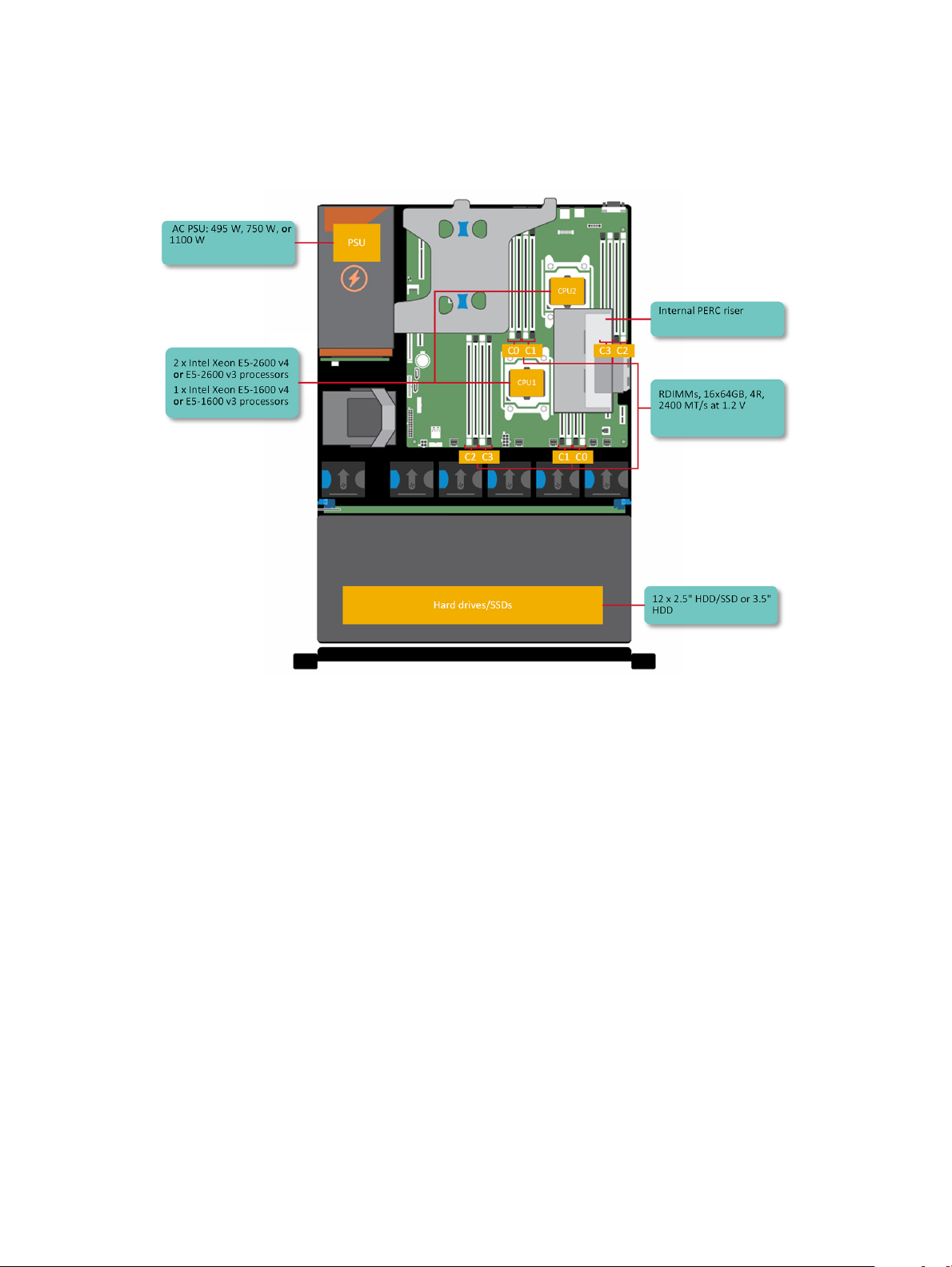
Supported congurations for the Dell DSS 2500
system
Figure 1. Supported congurations for the DSS 2500 system
8
Dell DSS 2500 system overview
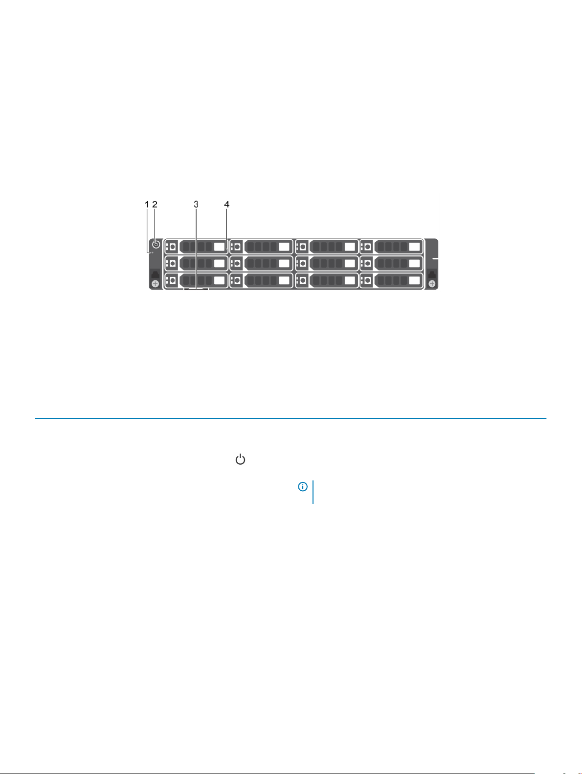
Front panel
The front panel provides access to the features available on the front of the server, such as the power button, NMI button, system
identication tag, system identication button, and USB and VGA ports. The hot swappable hard drives are accessible from the front panel.
12 x 3.5-inch or 2.5-inch hard drives/SSDs system
Figure 2. Front panel features of a 12 x 3.5-inch or 2.5-inch hard drives/SSDs system
1
diagnostic indicators 2 power button
3 information tag 4 hard drives or SSDs
Table 1. Front panel features of a 12 x 3.5-inch or 2.5-inch hard drives/SSDs system
Item Indicator, button, or connector Icon Description
1 Diagnostic indicators The diagnostic indicators light up to display error status. For more
information, see the Diagnostic indicators section.
2 Power button
3 Information tag
4 Hard drives or SSDs Up to twelve 3.5 inch or 2.5 inch (in a hybrid drive carrier) hot-
Related links
Diagnostic indicators on the front panel
Drive specications
Indicates if the system is turned on or o. Press the power button
to manually turn on or o the system.
NOTE: Press the power button to gracefully shut down an
ACPI-compliant operating system.
The Information Tag is a slide-out label panel that contains system
information such as Service Tag, NIC, MAC address, and so on. If
you have opted for the secure default access to iDRAC, the
Information tag also contains the iDRAC secure default password.
swappable hard drives or SSDs.
Enable you to install drives that are supported on your system. For
more information about drives, see the Technical specications
section.
Dell DSS 2500 system overview
9
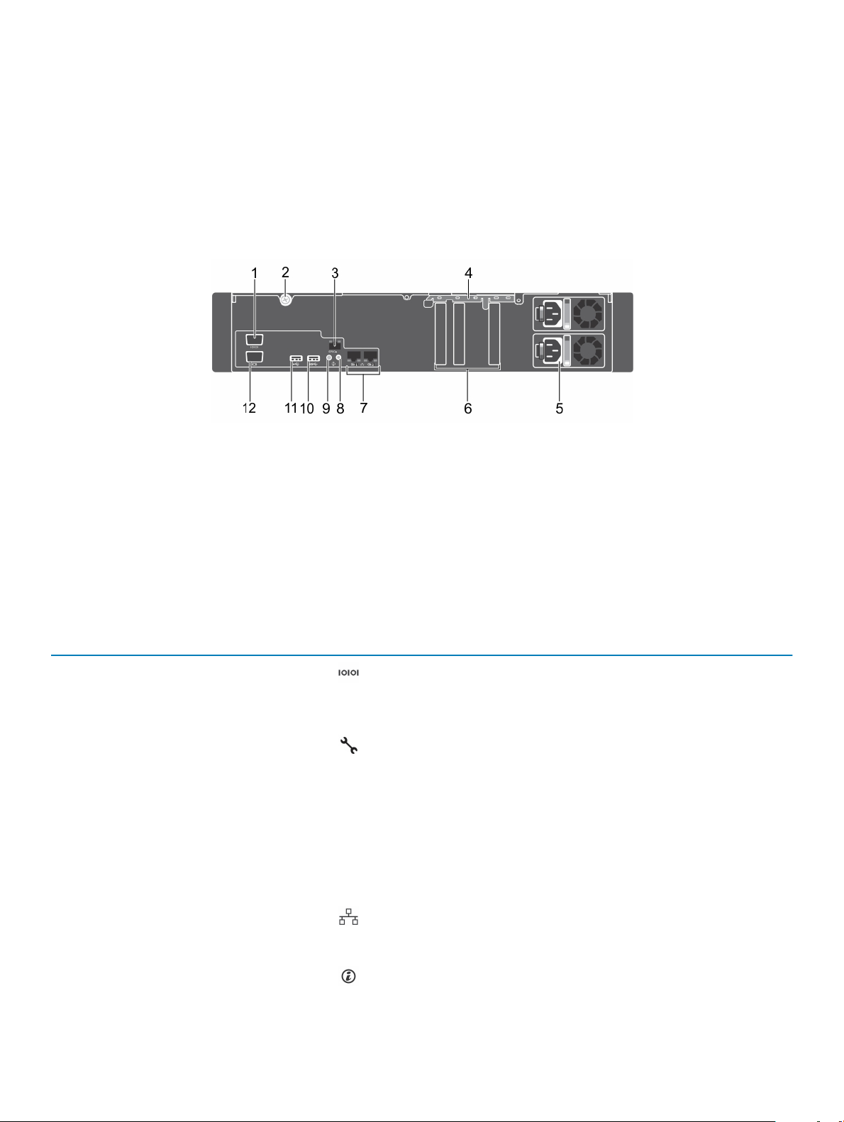
Back panel features
The back panel provides access to the features available on the back of the server, such as the system identication button, power supply
sockets, cable management arm connectors, NIC ports, and USB and VGA ports. A majority of the expansion card ports can be accessed
from the back panel. The hot swappable power supply units are accessible from the back panel.
System without dual riser module
Figure 3. Back panel features of a system without dual riser module
1
serial port 2 retention screw
3 BMC port (optional) 4 PCIe expansion card retainer
5 redundant power supply unit (2) 6 half height PCIe expansion card slots (3)
7 Ethernet ports (2) 8 system identication button
9 system identication port 10 USB 3.0 port
11 USB 2.0 port 12 video port
Table 2. Back panel features of a system without dual riser module
Item Indicator, button, or connector Icon Description
1 Serial port
2 Retention screw Use the retention screw to secure the system cover to the chassis.
3 BMC port (optional) Use the dedicated management port for the BMC ports card.
4 PCIe expansion card retainer Use the PCIe expansion card retainer to lock the PCIe card in place.
5 Redundant power supply unit (2) 495 W EPP, 750 W EPP, or 1100 W EPP
6 Half height PCIe expansion card
slots (3)
7 Ethernet connectors (2) Use the Ethernet port to connect Local Area Networks (LANs) to
8 System identication button Press the system ID button:
Enables you to connect a serial device to the system. For more
information, see the Technical specications section.
PSU1 is the primary PSU of the system. For more information, see
the Technical specications section.
Use the card slots to connect up to three half-height PCIe
expansion cards.
the system. For more information about the supported Ethernet
ports, see the Technical specications section.
1 To locate a particular system within a rack
10 Dell DSS 2500 system overview
Item Indicator, button, or connector Icon Description
2 To turn the system ID on or o.
NOTE: To reset BMC using system ID, ensure that the
system ID button is enabled in the BMC setup.
NOTE: If the system stops responding during POST, press
and hold the system ID button (for more than ve
seconds) to enter the BIOS progress mode.
9 System identication port Use the system identication port to connect the system status
indicator assembly through the optional cable management arm.
10 USB port Use the USB 3.0 port to connect USB devices to the system.
These ports are 9-pin, USB 3.0 compliant.
11 USB port Use the USB 2.0 port to connect USB devices to the system.
These ports are 4-pin, USB 2.0 compliant.
12 Video port Use the video/VGA port to connect a display to the system. For
more information about the supported video/VGA port, see the
Technical specications section.
Related links
Serial connector
PSU specications
USB ports
NIC ports
VGA port
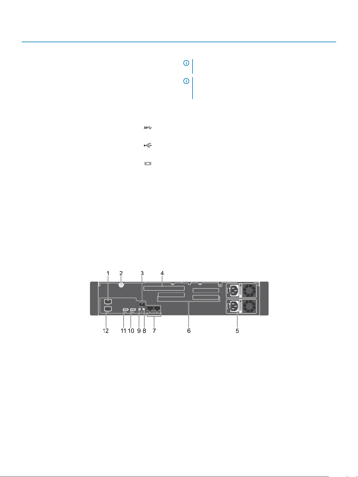
System with dual riser module
Figure 4. Back panel features of a system with dual riser module
serial port 2 retention screw
1
3 BMC port (optional) 4 full height, full length PCIe expansion card slot (1)
5 redundant power supply unit (2) 6 half height PCIe expansion card slots (3)
7 Ethernet ports (2) 8 system identication button
9 system identication port 10 USB 3.0 port
11 USB 2.0 port 12 video port
Dell DSS 2500 system overview 11

Table 3. Back panel features of a system with dual riser module
Item Indicator, button, or connector Icon Description
1 Serial port
2 Retention screw Use the retention screw to secure the system cover to the chassis.
3 BMC port (optional) Use the dedicated management port for the BMC ports card.
Enables you to connect a serial device to the system. For more
information, see the Technical specications section.
4 Full height, full length PCIe
Expansion card slot (1)
5 Redundant power supply unit (2) 495 W EPP, 750 W EPP or 1100 W EPP
6 Half Height PCIe Expansion card
slots (3)
7 Ethernet ports (2) Use the Ethernet port to connect Local Area Networks (LANs) to
8 System identication button
Use the card slots to connect up to one full-height PCIe expansion
cards.
PSU1 is the primary PSU of the system. For more information, see
the Technical specications section.
Use the card slots to connect up to three half-height PCIe
expansion cards.
the system. For more information about the supported Ethernet
ports, see the Technical specications section
Press the system ID button:
• To locate a particular system within a rack.
• To turn the system ID on or o.
To reset BMC, press and hold the button for more than 15 seconds.
NOTE: To reset BMC using system ID, ensure that the
system ID button is enabled in the BMC setup.
NOTE: If the system stops responding during POST, press
and hold the system ID button (for more than ve
seconds) to enter the BIOS progress mode.
9 System identication port
10 USB port Use the USB 3.0 port to connect USB devices to the system.
11 USB port Use the USB 2.0 port to connect USB devices to the system.
12 Video port
Related links
Serial connector
PSU specications
USB ports
NIC ports
VGA port
Dell DSS 2500 system overview
12
The System identication port connects the optional system status
indicator assembly to the system through the optional cable
management arm.
These ports are 9-pin, USB 3.0 compliant.
These ports are 4-pin, USB 2.0 compliant.
Enables you to connect a display device to the system. For more
information, see the Technical specications section.

Diagnostic indicators on the front panel
The diagnostic indicators on the system front panel display error status during system startup.
NOTE: No diagnostic indicators are lit when the system is turned o. To turn on the system, plug it into a working power source
and press the power button.
Table 4. Diagnostic indicators
Icon Description Condition Corrective action
Related link
Getting help
Health indicator The indicator turns solid blue if the
system is in good health.
The indicator blinks amber:
• When the system is turned on.
• When the system is in standby.
• If any error condition exists. For
example, a failed fan, power
supply unit (PSU), or a hard drive.
None required.
Check the System Event Log or system messages for the
specic issue. For more information about error
messages, see the Dell Event and Error Messages
Reference Guide at Dell.com/openmanagemanuals >
OpenManage software.
The POST process is interrupted without any video
output due to invalid memory congurations. See the
Getting help section.
Dell DSS 2500 system overview
13
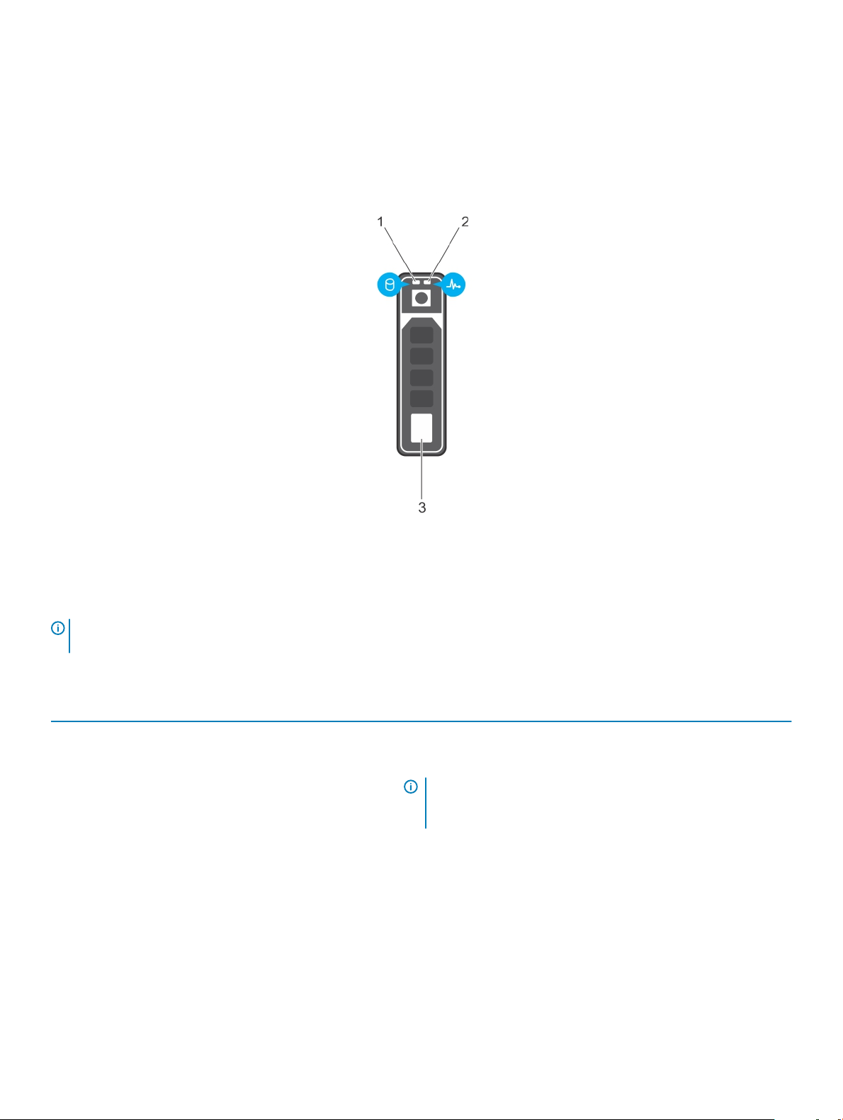
Hard drive indicator codes
Each hard drive carrier has an activity indicator and a status indicator. The indicators provide information about the current status of the
hard drive. The activity LED indicates whether hard drive is currently in use or not. The status LED indicates the power condition of the
hard drive.
Figure 5. Hard drive indicators
1
Hard drive activity indicator 2 Hard drive status indicator
3 Hard drive
NOTE: If the hard drive is in the Advanced Host Controller Interface (AHCI) mode, the status indicator (on the right side) does
not turn on.
Table 5. Hard drive indicator codes
Drive-status indicator pattern Condition
Flashes green twice per second Identifying drive or preparing for removal.
O Drive ready for insertion or removal.
NOTE: The drive status indicator remains o until all hard
drives are initialized after the system is turned on. Drives are
not ready for insertion or removal during this time.
Flashes green, amber, and then turns o Predicted drive failure
Flashes amber four times per second Drive failed
Flashes green slowly Drive rebuilding
Steady green Drive online
Flashes green for three seconds, amber for three seconds, and
then turns o after six seconds
Rebuild stopped
14 Dell DSS 2500 system overview
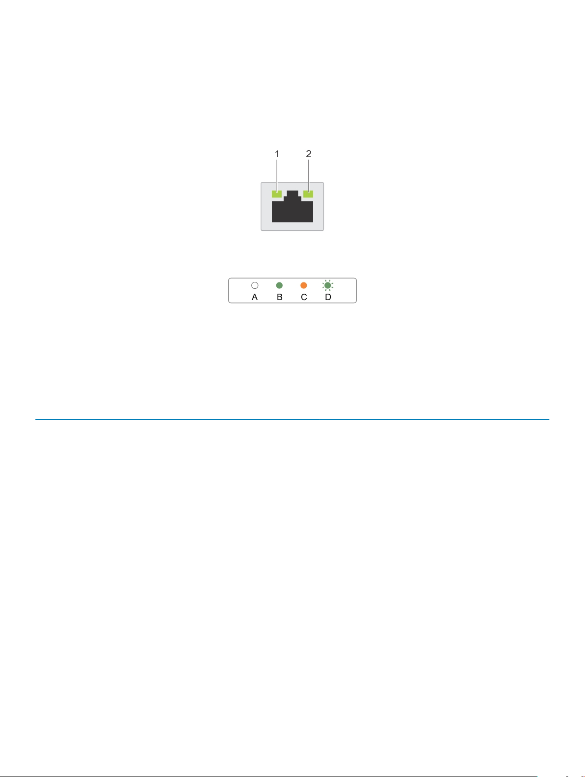
NIC indicator codes
The NIC on the back panel has an indicator that provides information about the network activity and link status. The activity LED indicates
whether the NIC is currently connected or not. The link LED indicates the speed of the connected network.
Figure 6. NIC indicators
1
link indicator 2 activity indicator
Table 6. NIC indicators
Convention Status Condition
A Link and activity indicators are o The NIC is not connected to the network.
B Link indicator is green The NIC is connected to a valid network at its maximum
port speed (1 Gbps or 10 Gbps).
C Link indicator is amber The NIC is connected to a valid network at less than its
maximum port speed.
D Activity indicator is ashing green Network data is being sent or received.
Redundant power supply unit indicator codes
Each AC power supply unit (PSU) has an illuminated translucent handle that indicates whether power is present or whether a power fault
has occurred.
Dell DSS 2500 system overview
15

Figure 7. AC PSU status indicator
1 AC PSU status indicator/handle
Table 7. AC PSU status indicator
Convention Power Indicator
Pattern
A Green A valid power source is connected to the PSU and the PSU is operational.
B Flashing green When the rmware of the PSU is being updated, the PSU handle ashes green.
C Flashes green and
turns o
D Flashing amber Indicates a problem with the PSU.
Description
CAUTION: Do not disconnect the power cord or unplug the PSU when updating
rmware. If rmware update is interrupted, the PSUs will not function.
When hot-adding a PSU, the PSU handle ashes green ve times at 4 Hz rate and turns
o. This indicates that there is a PSU mismatch with respect to eciency, feature set,
health status, and supported voltage.
CAUTION: For AC PSUs, use only PSUs with the Extended Power Performance
(EPP) label on the back.
NOTE: Ensure that both the PSUs are of the same capacity.
NOTE: Mixing PSUs from previous generations of Dell servers can result in a
PSU mismatch condition or failure to turn the system on.
CAUTION: When correcting a PSU mismatch, replace only the PSU with the
ashing indicator. Swapping the other PSU to make a matched pair can result in
an error condition and unexpected system shutdown. To change from a High
Output conguration to a Low Output conguration or vice versa, you must turn
o the system.
16 Dell DSS 2500 system overview
CAUTION: AC PSUs support both 220 V and 110 V input voltages with the
exception of Titanium PSUs, which support only 220 V. When two identical
PSUs receive dierent input voltages, they can output dierent wattages, and
trigger a mismatch.

Convention Power Indicator
Pattern
E Not lit Power is not connected.
Description
CAUTION: If two PSUs are used, they must be of the same type and have the
same maximum output power.
Locating service tag of your system
Your system is identied by a unique Express Service Code and Service Tag number. The Express Service Code is and Service Tag are
found on the front of the system by pulling out the information tag. Alternatively, the information may be on a sticker on the chassis of the
system. This information is used by Dell to route support calls to the appropriate personnel.
Dell DSS 2500 system overview 17

Documentation resources
This section provides information about the documentation resources for your system.
Table 8. Documentation resources for system
Task Document Location
Setting up your system
For information about installing the system into a rack,
see the Rack documentation included with your rack
solution.
Dell.com/dssmanuals
2
For information about turning on the system and the
technical specications of your system, see the
Getting Started With Your System that shipped with
your system.
Conguring your system For information about BMC features, conguring and
logging in to BMC, and managing your system
remotely, see the Integrated Dell Remote Access
Controller User's Guide.
For information about installing the operating system,
see the operating system documentation.
For understanding Remote Access Controller Admin
(RACADM) subcommands and supported RACADM
interfaces, see the RACADM Command Line
Reference Guide for iDRAC.
For information about updating drivers and rmware,
see the Methods to download rmware and drivers
section in this document.
Working with Dell
PowerEdge RAID
controllers
Understanding event
and error messages
For understanding the features of the Dell PowerEdge
RAID controllers (PERC) and deploying the PERC
cards, see the Storage controller documentation.
For information about the event and error messages
generated by the system rmware and agents that
monitor system components, see the Error Code
Lookup.
Dell.com/dssmanuals
Dell.com/poweredgemanuals
Dell.com/operatingsystemmanuals
Dell.com/poweredgemanuals
Dell.com/support/drivers
Dell.com/storagecontrollermanuals
Dell.com/qrl
BMC FAQs For frequently asked questions about BMC, see the
Dell BMC FAQ guide.
18 Documentation resources
Dell.com/dssmanuals
Technical specications
The technical and environmental specications of your system are outlined in this section.
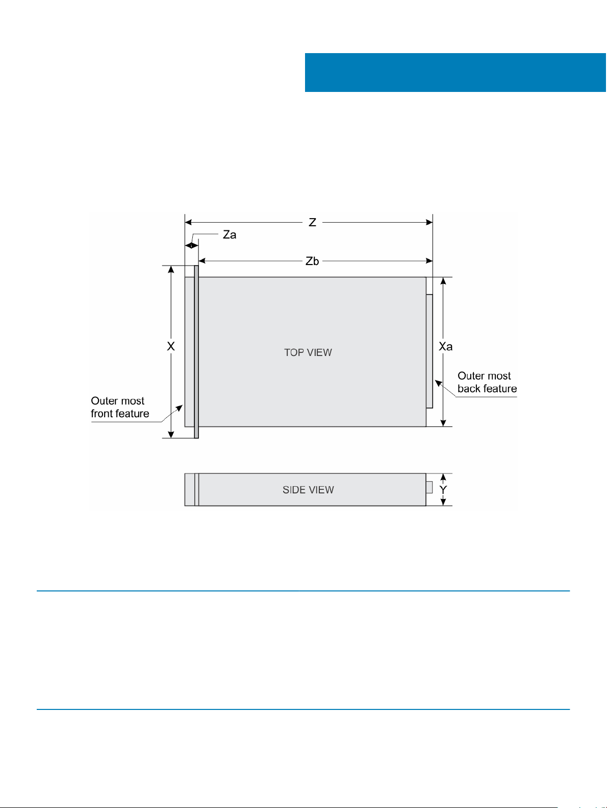
Chassis dimensions
3
Figure 8. Chassis dimensions of DSS 2500
Table 9. Dimensions of the DSS 2500 system
System X Xa Y Za Zb Z
12 x 3.5-inch or 2.5-inch hard
drive systems
482.4 mm (18.9
inch)
434.0 mm (17.08
inch)
86.8 mm (3.41
inch)
20.1 mm (0.79
inch)
646.7 mm
(25.46 inch)
Chassis weight
Table 10. Chassis weight
System Maximum weight
12 x 3.5-inch hard drive or 2.5-inch hard drive/SSD systems 28.2 kg (62.17 lb)
Technical specications 19
666.8 mm
(26.25 inch)

Processor specications
The DSS 2500 system supports up to two Intel Xeon E5-2600 v4 or E5-2600 v3 product family processors or a single Intel Xeon E5-1600
v4 or E5-1600 v3 product family processor.
PSU specications
The DSS 2500 system supports up to two AC redundant power supply units (PSUs).
Table 11. PSU specications
PSU Class Heat dissipation
(maximum)
495 W AC Platinum 1908 BTU/hr 50/60 Hz 100–240 V AC,
750 W AC Platinum 2891 BTU/hr 50/60 Hz 100–240 V AC,
1100 W AC Platinum 4100 BTU/hr 50/60 Hz 100–240 V AC,
NOTE: Heat dissipation is calculated by using the PSU wattage rating.
NOTE: This system is also designed to connect to the IT power systems with a phase-to-phase voltage not exceeding 230 V.
Frequency Voltage Current
6.5 A-3 A
autoranging
10 A-5 A
autoranging
12 A-6.5 A
autoranging
System battery specications
The DSS 2500 system supports CR 2032 3.0-V lithium coin cell system battery.
Storage controller specications
The DSS 2500 system supports PERC H330, PERC H730, and PERC H730P storage controllers.
Expansion bus specications
The Dell DSS 2500 system supports PCI express (PCIe) generation 3 expansion cards, which can be installed on the system board directly
or by using expansion card risers. The following tables provide detailed information about the expansion bus specications:
Table 12. Expansion slots (with optional expansion card risers)
Expansion slots (with
optional expansion card
risers)
Dual riser module Slot 1 Full height Full Length x16
Internal PERC riser Slot 5 Low Prole Half Length x8
20 Technical specications
PCIe slots on the riser Height Length Link
Slot 2 Low Prole Half Length x8
Slot 3 Low Prole Half Length x8
Slot 4 Low Prole Half Length x8
specications

Table 13. Expansion slots (without optional expansion card risers) specications
Expansion slots (without
optional expansion card
risers)
PCIe slots Slot 1 Low Prole Half Length x16
PCIe slots on the system
board
Slot 2 Low Prole Half Length x16
Slot 3 Low Prole Half Length x4
Height Length Link
Memory specications
The DSS 2500 system supports DDR4 registered DIMMs (RDIMMs) at 1866 MT/s, 2133 MT/s, or 2400 MT/s.
Table 14. Memory specications
Memory module sockets Memory capacity Minimum RAM Maximum RAM
sixteen 288-pins
8 GB and 16 GB (RDIMMs)
• 8 GB with single processor
• 16 GB with dual processors
(minimum one memory
module per processor)
• Up to 256 GB with single
processor
• Up to 512 GB with dual
processors
Drive specications
The DSS 2500 system supports:
• Up to twelve 3.5 inch or 2.5 inch (with 3.5 inch drive carrier adapters), hot-swappable SAS, SATA, or Nearline SAS hard drives
• Up to twelve 3.5 inch or 2.5 inch (with hybrid drive carriers), hot-swappable SATA SSDs
• Up to two 2.5 inch, internal cabled SATA hard drives
NOTE
: These internal drives are used only for the operating system. They will not be controlled by the RAID controller. These
hard drives are controlled by the PCH chipset.
Ports and connectors specications
USB ports
The DSS 2500 system supports USB 2.0 and 3.0-compliant ports on the back panel.
Table 15. USB
System Back panel
12 x 3.5-inch or 2.5-inch hard drive/SSD
NIC ports
specications
• One 9-pin, USB 3.0-compliant port
• One 4-pin, USB 2.0-compliant port
The DSS 2500 system supports two 10/100/1000 Mbps Network Interface Controller (NIC) ports on the back panel.
Technical
specications 21

VGA port
The Video Graphic Array (VGA) port enables you to connect the system to a VGA display. The DSS 2500 system supports one 15-pin VGA
port on the back panel.
Remote management port
The DSS 2500 system supports one dedicated 1Gbe Ethernet port with optional card and up to two optional shared NIC ports.
Serial connector
The serial connector connects a serial device to the system. The DSS 2500 system supports one serial connector on the back panel, which
is a 9-pin connector, Data Terminal Equipment (DTE), 16550-compliant.
Internal SAS connector
The DSS 2500 system supports one internal Mini-SAS connector.
Video specications
The DSS 2500 system supports Integrated Matrox G200 graphics card with 16 MB capacity.
Environmental specications
NOTE
: For additional information about environmental measurements for specic system congurations, see Dell.com/
environmental_datasheets.
Table 16. Temperature specications
Temperature Specications
Storage –40°C to 65°C (–40°F to 149°F)
Continuous operation (for altitude less than 950 m or 3117 ft) 10°C to 35°C (50°F to 95°F) with no direct sunlight on the
equipment.
NOTE: Maximum of 145 W 22 core processor is supported
in systems with eight 2.5-inches drives, two PCI slot
chassis, and 75 W single wide active GPU.
Fresh air For information about fresh air, see Expanded Operating
Temperature section.
Maximum temperature gradient (operating and storage) 20°C/h (36°F/h)
22 Technical specications

Table 17. Relative humidity specications
Relative humidity Specications
Storage 5% to 95% RH with 33°C (91°F) maximum dew point. Atmosphere
must be non-condensing at all times.
Operating 10% to 80% relative humidity with 29°C (84.2°F) maximum dew
point.
Table 18. Maximum vibration specications
Maximum vibration Specications
Operating 0.26 G
Storage 1.88 G
Table 19. Maximum shock specications
Maximum shock Specications
Operating Six consecutively executed shock pulses in the positive and
negative x, y, and z axes of 40 G for up to 2.3 ms.
Storage Six consecutively executed shock pulses in the positive and
negative x, y, and z axes (one pulse on each side of the system) of
71 G for up to 2 ms.
Table 20. Maximum altitude specications
Maximum altitude Specications
Operating
Storage 12,000 m (39,370 ft)
Table 21. Operating temperature de-rating specications
3048 m (10,000 ft)
at 5 Hz to 350 Hz (all operation orientations).
rms
at 10 Hz to 500 Hz for 15 min (all six sides tested).
rms
Operating temperature de-rating Specications
Up to 35°C (95°F) Maximum temperature is reduced by 1°C/300 m (1°F/547 ft)
above 950 m (3,117 ft).
35°C to 40°C (95°F to 104°F) Maximum temperature is reduced by 1°C/175 m (1°F/319 ft) above
950 m (3,117 ft).
40°C to 45°C (104°F to 113°F) Maximum temperature is reduced by 1°C/125 m (1°F/228 ft) above
950 m (3,117 ft).
Particulate and gaseous contamination specications
The following table denes the limitations that help avoid any equipment damage or failure from particulates and gaseous contamination. If
the levels of particulates or gaseous pollution exceed the specied limitations and result in equipment damage or failure, you may need to
rectify the environmental conditions. Re-mediation of environmental conditions is the responsibility of the customer.
Technical
specications 23

Table 22. Particulate contamination specications
Particulate contamination Specications
Air ltration Data center air ltration as dened by ISO Class 8 per ISO 14644-1
with a 95% upper condence limit.
NOTE: This condition applies only to data center
environments. Air ltration requirements do not apply to IT
equipment designed to be used outside a data center, in
environments such as an oce or factory oor.
NOTE: Air entering the data center must have MERV11 or
MERV13 ltration.
Conductive dust Air must be free of conductive dust, zinc whiskers, or other
conductive particles.
NOTE: This condition applies to data center and non-data
center environments.
Corrosive dust
Table 23. Gaseous contamination specications
Gaseous contamination Specications
Copper coupon corrosion rate <300 Å/month per Class G1 as dened by ANSI/ISA71.04-1985.
Silver coupon corrosion rate <200 Å/month as dened by AHSRAE TC9.9.
NOTE: Maximum corrosive contaminant levels measured at ≤50% relative humidity.
• Air must be free of corrosive dust.
• Residual dust present in the air must have a deliquescent point
less than 60% relative humidity.
NOTE: This condition applies to data center and non-data
center environments.
Expanded operating temperature
Table 24. Expanded operating temperature
Expanded operating temperature Specications
Continuous operation 5°C to 40°C at 5% to 85% RH with 29°C dew point.
specications
NOTE: Outside the standard operating temperature (10°C to
35°C), the system can operate continuously in temperatures as low
as 5°C and as high as 40°C.
For temperatures between 35°C and 40°C, de-rate maximum allowable dry
bulb temperature by 1°C per 175 m above 950 m (1°F per 319 ft).
< 1% of annual operating hours –5°C to 45°C at 5% to 90% RH with 29°C dew point.
24 Technical specications

Expanded operating temperature Specications
NOTE: Outside the standard operating temperature (10°C to
35°C), the system can operate down to –5°C or up to 45°C for a
maximum of 1% of its annual operating hours.
For temperatures between 40°C and 45°C, de-rate maximum allowable
temperature by 1°C per 125 m above 950 m (1°F per 228 ft).
NOTE: When operating in the expanded temperature range, system performance may be impacted.
NOTE: When operating in the expanded temperature range, ambient temperature warnings maybe reported in the System Event
Log.
Technical specications 25

4
Initial system setup and conguration
Setting up your system
Complete the following steps to set up your system:
1 Unpack the system.
2 Install the system into the rack. For more information about installing the system into the rack, see your system Rack Installation
Placemat
3 Connect the peripherals to the system.
4 Connect the system to its electrical outlet.
5 Turn the system on by pressing the power button.
6 Turn on the attached peripherals.
Options to set up BMC IP address
You must congure the initial network settings based on your network infrastructure to enable the communication to and from BMC. You
can set up the IP address by using one of the following interfaces:
at Dell.com/dssmanuals.
Interfaces
iDRAC Settings
utility
Dell Deployment
Toolkit
Remote Access
Controller Admin
(RACADM)
Remote Services
that include Web
Services
Management (WSMan)
You must use the default BMC IP address 192.168.0.120 to congure the initial network settings, including setting up DHCP or a static IP for
BMC.
: To access BMC, ensure that you install the remote management port card or connect the network cable to the Ethernet
NOTE
connector 1 on the system board.
NOTE: Ensure that you change the default user name and password after setting up the BMC IP address.
Document/Section
See Dell Integrated Dell Remote Access Controller User's Guide at Dell.com/idracmanuals
See Dell Deployment Toolkit User’s Guide at Dell.com/openmanagemanuals
See RACADM Command Line Interface Reference Guide and Integrated Dell Remote Access Controller User's
Guide at Dell.com/idracmanuals
See Dell Integrated Dell Remote Access Controller User's Guide at Dell.com/idracmanuals
Log in to BMC
You can log in to BMC as:
26 Initial system setup and conguration

• BMC local user
• Microsoft Active Directory user
• Lightweight Directory Access Protocol (LDAP) user
The default user name and password are root and calvin. You can also log in by using Single Sign-On or Smart Card.
NOTE: You must have BMC local credentials to log in to BMC local.
For more information about logging in to iDRAC and iDRAC licenses, see the latest Integrated Dell Remote Access Controller User's Guide
at Dell.com/idracmanuals.
You can also access iDRAC by using RACADM. For more information, see the RACADM Command Line Interface Reference Guide and the
Integrated Dell Remote Access Controller User's Guide available at Dell.com/idracmanuals.
Options to install the operating system
If the system is shipped without an operating system, install the supported operating system by using one of the following resources:
Table 25. Resources to install the operating system
Resources Location
Dell Systems Management Tools and Documentation media Dell.com/operatingsystemmanuals
Dell certied VMware ESXi Dell.com/virtualizationsolutions
Supported operating systems on Dell DSS systems Dell.com/ossupport
Methods to download rmware and drivers
You can download the rmware and drivers by using any of the following methods:
Table 26. Firmware and drivers
Methods Location
From the Dell Support site Global Technical Support
Using BMC Dell.com/idracmanuals
Downloading the drivers and rmware
Dell EMC recommends that you download and install the latest BIOS, drivers, and systems management rmware on your system.
Prerequisite
Ensure that you clear the web browser cache before downloading the drivers and rmware.
Steps
1 Go to Dell.com/support/drivers.
2 In the Drivers & Downloads section, type the Service Tag of your system in the Service Tag or Express Service Code box, and then
click Submit.
: If you do not have the Service Tag, select Detect My Product to allow the system to automatically detect your
NOTE
Service Tag, or in General support, navigate to your product.
3 Click Drivers & Downloads.
The drivers that are applicable to your selection are displayed.
Initial system setup and
conguration 27

4 Download the drivers to a USB drive, CD, or DVD.
28 Initial system setup and conguration

Pre-operating system management applications
You can manage basic settings and features of a system without booting to the operating system by using the system rmware.
Topics:
• Options to manage the pre-operating system applications
• System Setup
• Boot Manager
• PXE boot
Options to manage the pre-operating system applications
Your system has the following options to manage the pre-operating system applications:
• System Setup
• Boot Manager
• Preboot Execution Environment (PXE)
5
Related links
System Setup
Boot Manager
PXE boot
System Setup
By using the System Setup screen, you can congure the BIOS settings, BMCsettings, and device settings of your system.
: Help text for the selected eld is displayed in the graphical browser by default. To view the help text in the text browser,
NOTE
press F1.
You can access system setup by using two methods:
• Standard graphical browser — The browser is enabled by default.
• Text browser — The browser is enabled by using Console Redirection.
Related links
System Setup details
Viewing System Setup
Pre-operating system management applications 29

Viewing System Setup
To view the System Setup screen, perform the following steps:
1 Turn on, or restart your system.
2 Press F2 immediately after you see the following message:
F2 = System Setup
NOTE: If your operating system begins to load before you press F2, wait for the system to nish booting, and then restart
your system and try again.
Related links
System Setup
System Setup details
System Setup details
The System Setup Main Menu screen details are explained as follows:
Option Description
System BIOS Enables you to congure BIOS settings.
iDRAC Settings Enables you to congure BMC settings.
The iDRAC settings utility is an interface to set up and congure the BMC parameters by using UEFI. You can
enable or disable various BMC parameters by using the iDRAC settings utility. For more information about this
utility, see Integrated Dell Remote Access Controller 8 User’s Guide at Dell.com/idracmanuals.
Device Settings Enables you to congure device settings.
Related links
System Setup
iDRAC Settings utility
Device Settings
Viewing System Setup
System BIOS
You can use the System BIOS screen to edit specic functions such as boot order, system password, setup password, set the RAID mode,
and enable or disable USB ports.
Pre-operating system management applications
30
 Loading...