

Page 1

Dell DR4300 System
Owner’s Manual
Regulatory Model: E31S Series
Regulatory Type: E31S001
Page 2

Notes, cautions, and warnings
NOTE: A NOTE indicates important information that helps you make better use of your computer.
CAUTION: A CAUTION indicates either potential damage to hardware or loss of data and tells you
how to avoid the problem.
WARNING: A WARNING indicates a potential for property damage, personal injury, or death.
© 2016 Dell Inc. All rights reserved. This product is protected by U.S. and international copyright and intellectual
property laws. Dell and the Dell logo are trademarks of Dell Inc. in the United States and/or other jurisdictions. All other
marks and names mentioned herein may be trademarks of their respective companies.
2016 - 05
Rev. A01
Page 3

Contents
1 Dell DR4300 system overview............................................................................8
Front panel features and indicators......................................................................................................8
Back panel features............................................................................................................................. 10
Diagnostic indicators on the front panel............................................................................................ 11
Hard drive indicator codes............................................................................................................ 13
NIC indicator codes.......................................................................................................................14
Power supply unit indicator codes............................................................................................... 14
iDRAC Direct LED indicator codes................................................................................................16
Quick Sync indicator codes...........................................................................................................17
Locating Service Tag of your system............................................................................................18
Documentation matrix........................................................................................................................18
2 Technical specifications....................................................................................20
Chassis dimensions.............................................................................................................................20
Chassis weight..................................................................................................................................... 21
Processor specifications......................................................................................................................21
PSU specifications............................................................................................................................... 21
System battery specifications..............................................................................................................21
Expansion bus specifications.............................................................................................................. 21
Memory specifications........................................................................................................................22
Drive specifications............................................................................................................................. 22
Hard drives.....................................................................................................................................22
Ports and connectors specifications..................................................................................................22
USB ports....................................................................................................................................... 22
NIC ports........................................................................................................................................23
Serial connector............................................................................................................................ 23
VGA ports.......................................................................................................................................23
Internal Dual SD Module............................................................................................................... 23
Video specifications............................................................................................................................ 23
Environmental specifications..............................................................................................................24
Particulate and gaseous contamination specifications .............................................................. 25
Standard operating temperature.................................................................................................. 26
Expanded operating temperature.................................................................................................26
Expanded operating temperature restrictions............................................................................. 27
3 Initial system setup and configuration...........................................................28
Setting up your system....................................................................................................................... 28
iDRAC configuration........................................................................................................................... 28
3
Page 4

Options to set up iDRAC IP address.............................................................................................28
Options to install the operating system............................................................................................. 29
Methods to download firmware and drivers................................................................................29
Manage your system...........................................................................................................................30
4 Pre-operating system management applications........................................32
Options to manage the pre-operating system applications............................................................. 32
System Setup.......................................................................................................................................32
Viewing System Setup...................................................................................................................33
System Setup details......................................................................................................................33
System BIOS.................................................................................................................................. 34
iDRAC Settings utility.....................................................................................................................57
Device Settings..............................................................................................................................58
Dell Lifecycle Controller..................................................................................................................... 58
Embedded system management..................................................................................................59
Boot Manager......................................................................................................................................59
Viewing Boot Manager..................................................................................................................59
Boot Manager main menu............................................................................................................ 59
PXE boot..............................................................................................................................................60
5 Installing and removing system components............................................... 61
Safety instructions............................................................................................................................... 61
Before working inside your system.................................................................................................... 61
After working inside your system....................................................................................................... 62
Recommended tools.......................................................................................................................... 62
Front bezel (optional)..........................................................................................................................62
Removing the optional front bezel...............................................................................................63
Installing the optional front bezel................................................................................................ 64
System cover.......................................................................................................................................65
Removing the system cover......................................................................................................... 65
Installing the system cover........................................................................................................... 66
Inside the system................................................................................................................................ 68
Cooling shroud................................................................................................................................... 69
Removing the cooling shroud......................................................................................................69
Installing the cooling shroud........................................................................................................ 70
Cooling fans........................................................................................................................................ 70
Removing a cooling fan.................................................................................................................71
Installing a cooling fan.................................................................................................................. 72
Cooling-fan assembly ........................................................................................................................72
Removing the cooling fan assembly............................................................................................ 72
Installing the cooling fan assembly.............................................................................................. 74
System memory...................................................................................................................................75
4
Page 5

General memory module installation guidelines......................................................................... 77
Mode-specific guidelines.............................................................................................................. 77
Sample memory configurations................................................................................................... 79
Removing memory modules........................................................................................................ 79
Installing memory modules..........................................................................................................80
Processors and heat sinks...................................................................................................................82
Removing a heat sink....................................................................................................................82
Removing a processor.................................................................................................................. 83
Installing a processor.................................................................................................................... 87
Installing a heat sink......................................................................................................................90
PCIe card holder................................................................................................................................. 92
Removing the PCIe card holder................................................................................................... 92
Installing the PCIe card holder..................................................................................................... 93
Opening and closing the PCIe card holder latch........................................................................ 94
Cable retention bracket...................................................................................................................... 95
Removing the cable retention bracket.........................................................................................95
Installing the cable retention bracket...........................................................................................96
Integrated storage controller card..................................................................................................... 97
Removing the integrated storage controller card....................................................................... 98
Installing the integrated storage controller card.......................................................................100
Expansion cards and expansion card riser.......................................................................................102
Expansion card installation guidelines....................................................................................... 102
Removing an expansion card from expansion card riser 2 or 3............................................... 102
Installing an expansion card into the expansion card riser 2 or 3.............................................104
Removing an expansion card from the expansion card riser 1................................................. 105
Installing an expansion card into the expansion card riser 1.....................................................107
Removing the riser 1 blank......................................................................................................... 108
Installing the riser 1 blank............................................................................................................110
Removing expansion card risers..................................................................................................111
Installing expansion card risers................................................................................................... 116
Internal dual SD module (optional)...................................................................................................119
Removing an internal SD card.................................................................................................... 120
Installing an internal SD card.......................................................................................................121
Removing the optional internal dual SD module.......................................................................122
Installing the optional internal dual SD module ........................................................................124
Network daughter card.....................................................................................................................124
Removing the network daughter card .......................................................................................125
Installing the network daughter card..........................................................................................127
Internal USB memory key (optional)................................................................................................ 129
Replacing the optional internal USB memory key..................................................................... 129
System battery...................................................................................................................................130
Replacing the system battery..................................................................................................... 130
5
Page 6

Power supply units (PSU).................................................................................................................. 132
Hot spare feature.........................................................................................................................132
Removing the power supply unit blank......................................................................................133
Installing the power supply unit blank........................................................................................134
Removing an AC power supply unit........................................................................................... 134
Installing an AC power supply unit............................................................................................. 135
System board.....................................................................................................................................136
Removing the system board....................................................................................................... 137
Installing the system board.........................................................................................................139
Trusted Platform Module..................................................................................................................142
Installing the Trusted Platform Module......................................................................................143
Initializing the TPM for BitLocker users......................................................................................144
Initializing the TPM for TXT users............................................................................................... 144
Hard drives.........................................................................................................................................144
Removing a 2.5 inch hard drive blank (rear)...............................................................................145
Installing a 2.5 inch hard drive blank (rear).................................................................................145
Removing a 3.5-inch hard drive blank....................................................................................... 146
Installing a 3.5-inch hard drive blank..........................................................................................147
Removing a hot swappable hard drive or SSD...........................................................................148
Installing a hot-swap hard drive................................................................................................. 149
Removing a hard drive from a hard drive carrier....................................................................... 150
Installing a hard drive into a hard drive carrier........................................................................... 151
Hard drive backplane........................................................................................................................ 152
Removing the hard drive backplane ..........................................................................................152
Installing the hard drive backplane ............................................................................................ 155
Removing the optional hard drive backplane (rear)...................................................................157
Installing the optional hard drive backplane (rear).....................................................................158
SD vFlash card (optional).................................................................................................................. 160
Replacing an optional SD vFlash media card.............................................................................160
Removing the vFlash media unit.................................................................................................161
Installing the vFlash media unit...................................................................................................162
Control panel assembly.................................................................................................................... 164
Removing the control panel ...................................................................................................... 164
Installing the control panel ........................................................................................................ 165
Removing the I/O panel ............................................................................................................. 167
Installing the I/O panel ...............................................................................................................168
6 Using system diagnostics................................................................................170
Dell Embedded System Diagnostics.................................................................................................170
When to use the Embedded System Diagnostics...................................................................... 170
Running the Embedded System Diagnostics from Boot Manager............................................170
Running the Embedded System Diagnostics from the Dell Lifecycle Controller..................... 171
6
Page 7

System diagnostic controls......................................................................................................... 171
7 Jumpers and connectors.................................................................................172
System board jumper settings.......................................................................................................... 172
System board jumpers and connectors........................................................................................... 173
Disabling a forgotten password........................................................................................................175
8 Troubleshooting your system........................................................................ 176
Safety first — for you and your system.............................................................................................176
Troubleshooting system startup failure............................................................................................176
Troubleshooting external connections............................................................................................176
Troubleshooting the video subsystem............................................................................................. 176
Troubleshooting a USB device..........................................................................................................177
Troubleshooting iDRAC Direct (USB XML configuration)................................................................178
Troubleshooting iDRAC Direct (Laptop connection)...................................................................... 178
Troubleshooting a serial I/O device................................................................................................. 179
Troubleshooting a NIC......................................................................................................................179
Troubleshooting a wet system.........................................................................................................180
Troubleshooting a damaged system................................................................................................ 181
Troubleshooting the system battery.................................................................................................181
Troubleshooting power supply units............................................................................................... 182
Troubleshooting power source problems................................................................................. 182
Troubleshooting power supply unit problems...........................................................................182
Troubleshooting cooling problems..................................................................................................183
Troubleshooting cooling fans.......................................................................................................... 184
Troubleshooting system memory....................................................................................................184
Troubleshooting an internal USB key...............................................................................................185
Troubleshooting an SD card.............................................................................................................186
Troubleshooting an optical drive......................................................................................................187
Troubleshooting a tape backup unit................................................................................................ 187
Troubleshooting a hard drive........................................................................................................... 188
Troubleshooting a storage controller.............................................................................................. 189
Troubleshooting expansion cards....................................................................................................190
Troubleshooting processors............................................................................................................. 191
System messages...............................................................................................................................191
Warning messages.......................................................................................................................191
Diagnostic messages................................................................................................................... 191
Alert messages.............................................................................................................................192
9 Getting help.......................................................................................................193
Contacting Dell................................................................................................................................. 193
Documentation feedback.................................................................................................................193
7
Page 8
GUID-55EF9839-C75B-402E-A494-34C1C4BEA016
1
Dell DR4300 system overview
Your Dell DR4300 system is 2U rack server that supports up to two Intel Xeon E5-2660 v3 processors, up
to 24 DIMMs, and twelve 3.5-inch hard drives and 2 optional 2.5-inch back-accessible hard drives for the
operating system.
GUID-A239E649-FE7D-4250-8087-41CA7891DE46
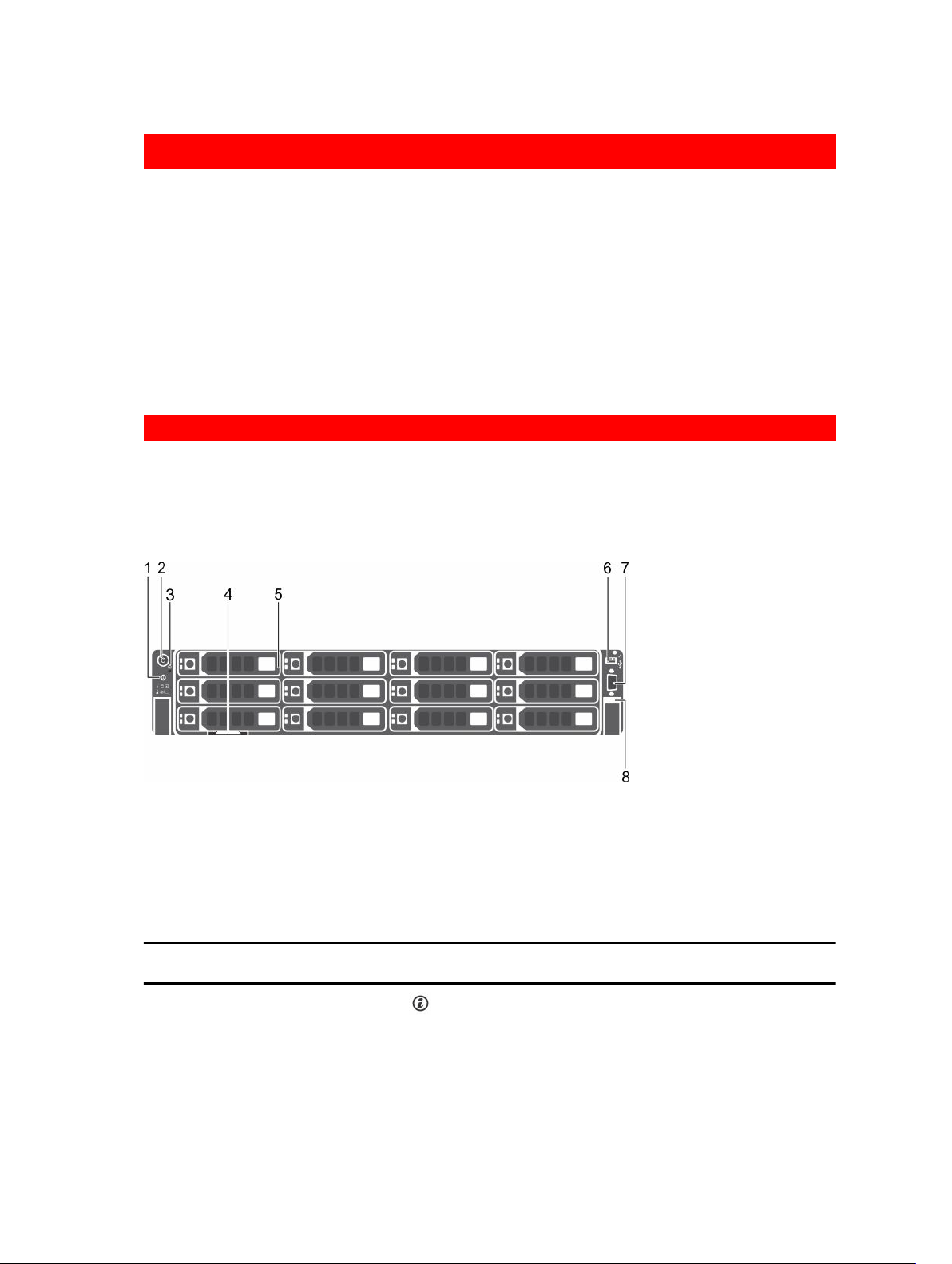
Front panel features and indicators
The front panel provides access to the features available on the front of the server, such as the power
button, NMI button, system identification tag, system identification button, and USB and VGA ports. The
diagnostic LEDs or the LCD panel is prominently on the front panel. The hot swappable hard drives are
accessible from the front panel.
Figure 1. Dell DR4300 system front panel features and indicators
1. System identification button 2. Power button
3. NMI button 4. Information tag
5. Hard drives 6. USB management port/iDRAC Direct
7. Video connector 8. Quick Sync
Table 1. Front panel features and indicators
Item Indicator, Button, or
Connector
1 System identification
button
8
Icon Description
Enables you to locate a particular system within a
rack. The identification buttons are on the front
and back panels.
Page 9

Item Indicator, Button, or
Connector
2 Power button Enables you to know the power status of the
Icon Description
Press the system identification button to turn the
system ID on or off.
NOTE:
• If the system stops responding during
POST, press and hold the system ID button
(for more than five seconds) to enter BIOS
progress mode.
• To reset the iDRAC (if not disabled in F2
iDRAC set up) press and hold the button
(for more than 15 seconds).
system. The power indicator turns on when the
system power is on. The power button controls
the power supply output to the system.
NOTE: On ACPI-compliant operating systems,
when the power button is used to shut down
the system, the operating system performs a
graceful shut down the system power is
turned off.
3 NMI button
4 Information tag Contains system information such as service tag,
5 Hard drives
6 USB management port/
iDRAC Direct
7 Video connector Enables you to connect a display to the system.
8 Quick Sync (optional)
Enables you to troubleshoot software and device
driver errors when running certain operating
systems. This button can be pressed by using the
end of a paper clip.
NOTE: Use this button only if directed to do
so by qualified support personnel or by
instructions in the operating system’s
documentation.
NIC, MAC address for your reference. The
information tag is a slide-out label panel.
Up to twelve 3.5-inch hot-swappable hard drives.
The USB management port is USB 2.0 compliant.
Enables you to connect USB devices to the system
or provides access to the iDRAC Direct features.
For more information, see the Integrated Dell
Remote Access Controller User’s Guide at
Dell.com/idracmanuals.
Indicates a Quick Sync enabled system. The Quick
Sync feature is optional and needs a Quick Sync
bezel. This feature allows management of the
system by using mobile devices. This feature
aggregates hardware or firmware inventory and
9
Page 10
Item Indicator, Button, or
Connector
Icon Description
various system level diagnostic and error
information that can be used in troubleshooting
the system. For more information, see the
Integrated Dell Remote Access Controller User’s
Guide at Dell.com/idracmanuals.
GUID-E3FAA996-0FEE-40CF-B480-BAF74A98856C
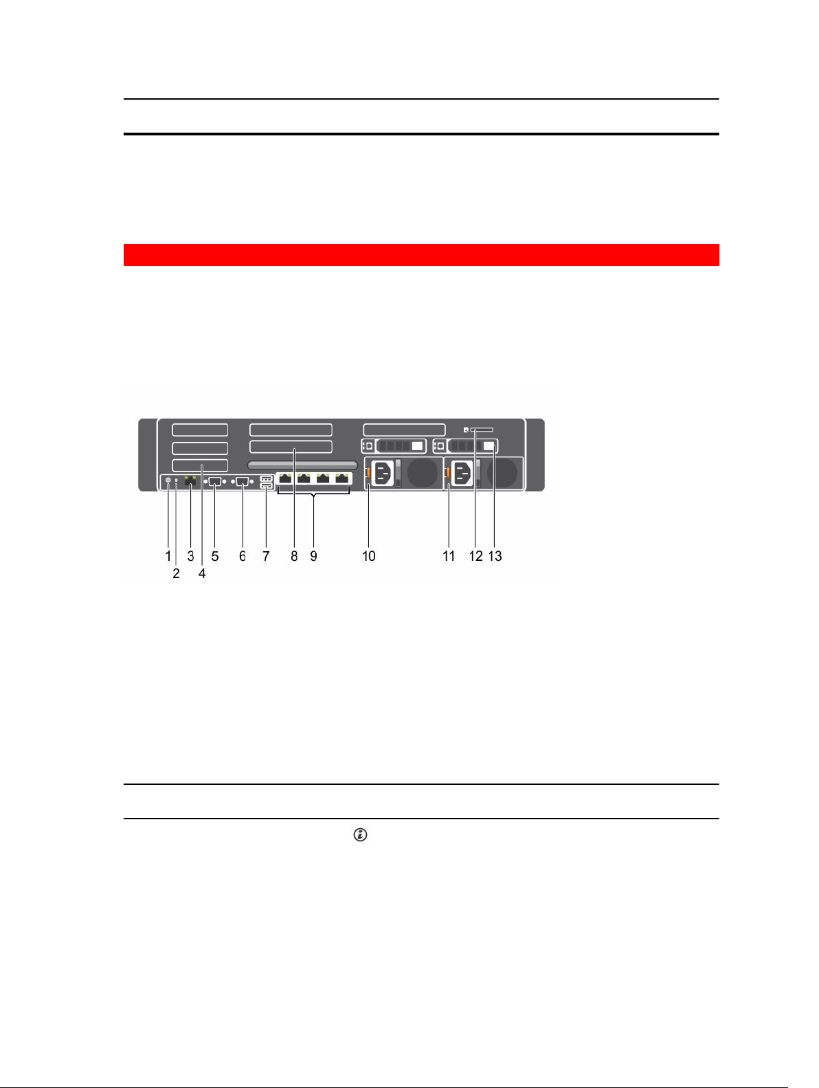
Back panel features
The back panel provides access to the features available on the back of the server, such as the system
identification button, power supply sockets, cable management arm connectors, iDRAC storage media,
NIC ports, USB and VGA ports. Most of the expansion card ports can be accessed from the back panel.
The hot swappable power supply units, and if installed, the rear accessible hard drives are accessible from
the back panel.
Figure 2. Back panel features
1. System identification button 2. System identification connector
3. iDRAC8 Enterprise port 4. Half-height PCIe expansion card slot
5. Serial connector 6. Video connector
7. USB port 8. Full-height PCIe expansion card slot
9. Ethernet connector 10. Power supply unit 1
11. Power supply unit 2 12. vFlash media card slot
13. Hard drive
Table 2. Back panel features
Item Indicator, button, or
connector
1 System identification
button
10
Icon Description
The identification buttons on the front and back
panels can be used to locate a particular system
within a rack.
Press to toggle the system identification (ID) on or
off.
Page 11

Item Indicator, button, or
connector
Icon Description
If the system stops responding during POST, press
and hold the system ID button for more than five
seconds to enter BIOS progress mode.
To reset iDRAC (if not disabled in F2 iDRAC set up)
press and hold the button for more than 15
seconds.
2 System identification
connector
3 iDRAC8 Enterprise port Dedicated management port.
4 Half-height PCIe
expansion card slot (3)
5 Serial connector Enables you to connect a serial device to the
6 Video connector Enables you to connect a VGA display to the
7 USB port (2) Enables you to connect USB devices to the system.
8 Full-height PCIe
expansion card slot (3)
9 Ethernet connector (4) Four integrated 10/100/1000 Mbps Network
Connects the optional system status indicator
assembly through the optional cable management
arm.
Enables you to connect up to 3 half-height PCI
Express expansion cards.
system.
system.
The ports are USB 3.0-compliant.
Enables you to connect up to 3 full-height PCI
Express expansion cards.
Interface Card (NIC) connectors
or
Four integrated connectors that include:
• Two 10/100/1000 Mbps NIC connectors
• Two 100 Mbps/1 Gbps/10 Gbps SFP+/10 GbE T
connectors
10 Power supply unit (PSU1)
11 Power supply unit
(PSU2)
AC 1100 W
AC 1100 W
GUID-7C7A87CF-08E8-43D0-8489-A73E2CD220DD
Diagnostic indicators on the front panel
NOTE: The diagnostic indicators are not present if the system is equipped with an LCD display.
NOTE: No diagnostic indicators are lit when the system is turned off. To start the system, plug it into
a working power source and press the power button.
11
Page 12

Table 3. Diagnostic indicators
Icon Description Condition Corrective action
Health
indicator
The indicator turns solid
blue if the system is in good
None required.
health.
Hard drive
indicator
Electrical
indicator
The indicator flashes amber:
• When the system is
turned on.
• When the system is in
standby.
• If any error condition
exists. For example, a
failed fan, PSU, or a hard
drive.
The indicator flashes amber
if there is a hard drive error.
The indicator flashes amber
if the system experiences an
electrical error (for example,
voltage out of range, or a
failed power supply unit
(PSU) or voltage regulator).
Check the System Event Log or system
messages for the specific issue. For more
information about error messages, see the
Dell Event and Error Messages Reference
Guide at Dell.com/openmanagemanuals >
OpenManage software.
The POST process is interrupted without
any video output due to invalid memory
configurations. See the Getting help
section.
Check the System Event Log to determine
the hard drive that has an error. Run the
appropriate Online Diagnostics test. Restart
the system and run embedded diagnostics
(ePSA). If the hard drives are configured in a
RAID array, restart the system and enter the
host adapter configuration utility program.
Check the System Event Log or system
messages for the specific issue. If it is due
to a problem with the PSU, check the LED
on the PSU. Reseat the PSU. If the problem
persists, see the Getting help section.
Temperature
indicator
The indicator flashes amber
if the system experiences a
thermal error (for example,
the ambient temperature is
out of range or fan failure).
Memory
indicator
The indicator flashes amber
if a memory error occurs.
Related Links
Getting help
Expansion card installation guidelines
12
Ensure that none of the following
conditions exist:
• A cooling fan has been removed or has
failed.
• System cover, cooling shroud, EMI filler
panel, memory module blank, or back
filler bracket is removed.
• Ambient temperature is too high.
• External airflow is obstructed.
See the Getting help section.
Check the system event log or system
messages for the location of the failed
memory. Reseat the memory module. If
the problem persists, see the Getting help
section.
Page 13
GUID-D913A428-0E1B-43BE-B607-F2C86F21B2DE
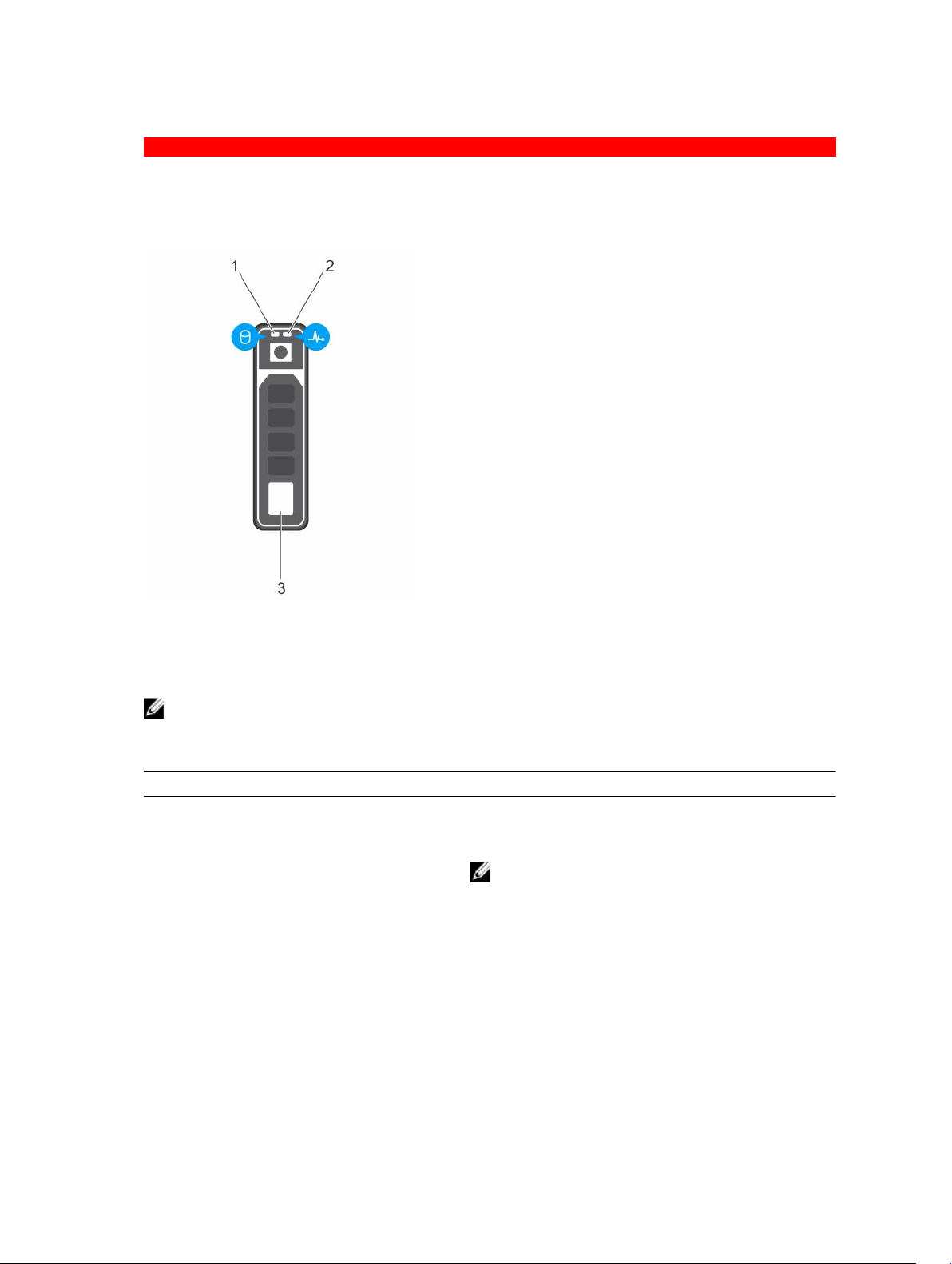
Hard drive indicator codes
Each hard drive carrier has an activity indicator and a status indicator. The indicators provide information
about the current status of the hard drive. The activity LED indicates whether hard drive is currently in use
or not. The status LED indicates the power condition of the hard drive.
Figure 3. Hard drive indicators
1. hard drive activity indicator 2. hard drive status indicator
3. hard drive
NOTE: If the hard drive is in the Advanced Host Controller Interface (AHCI) mode, the status
indicator (on the right side) does not turn on.
Table 4. Hard drive indicator codes
Drive-status indicator pattern (RAID only) Condition
Flashes green twice per second Identifying drive or preparing for removal.
Off Drive ready for insertion or removal.
NOTE: The drive status indicator remains off until
all hard drives are initialized after the system is
turned on. Drives are not ready for insertion or
removal during this time.
Flashes green, amber, and then turns off Predicted drive failure
Flashes amber four times per second Drive failed
Flashes green slowly Drive rebuilding
Steady green Drive online
13
Page 14
Drive-status indicator pattern (RAID only) Condition
Flashes green for three seconds, amber for
three seconds, and then turns off after six
seconds
Rebuild stopped
GUID-18C94A91-F205-4992-A1B2-BA2FF7C0D72E
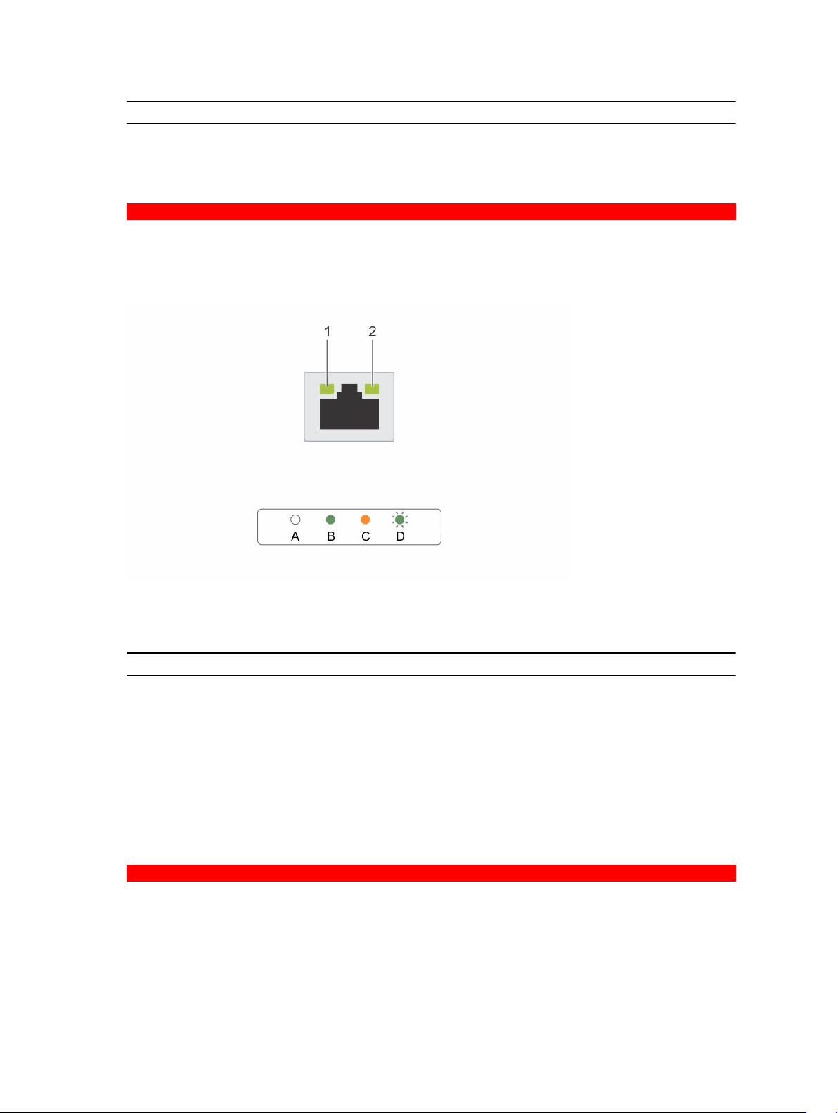
NIC indicator codes
Each NIC on the back panel has an indicator that provides information about the network activity and link
status. The activity LED indicates whether the NIC is currently connected or not. The link LED indicates
the speed of the connected network.
Figure 4. NIC indicators
1. link indicator 2. activity indicator
Table 5. NIC indicators
Convention Status Condition
A Link and activity indicators are off The NIC is not connected to the
network.
B Link indicator is green The NIC is connected to a valid network
at its maximum port speed (1 Gbps or 10
Gbps).
C Link indicator is amber The NIC is connected to a valid network
at less than its maximum port speed.
D Activity indicator is flashing green Network data is being sent or received.
GUID-FBD2281B-1608-4FF8-9AFE-4E33BB6FF810
Power supply unit indicator codes
AC power supply units (PSUs) have an illuminated translucent handle that serves as an indicator and DC
PSUs have an LED that serves as an indicator. The indicator shows whether power is present or a power
fault has occurred.
14
Page 15
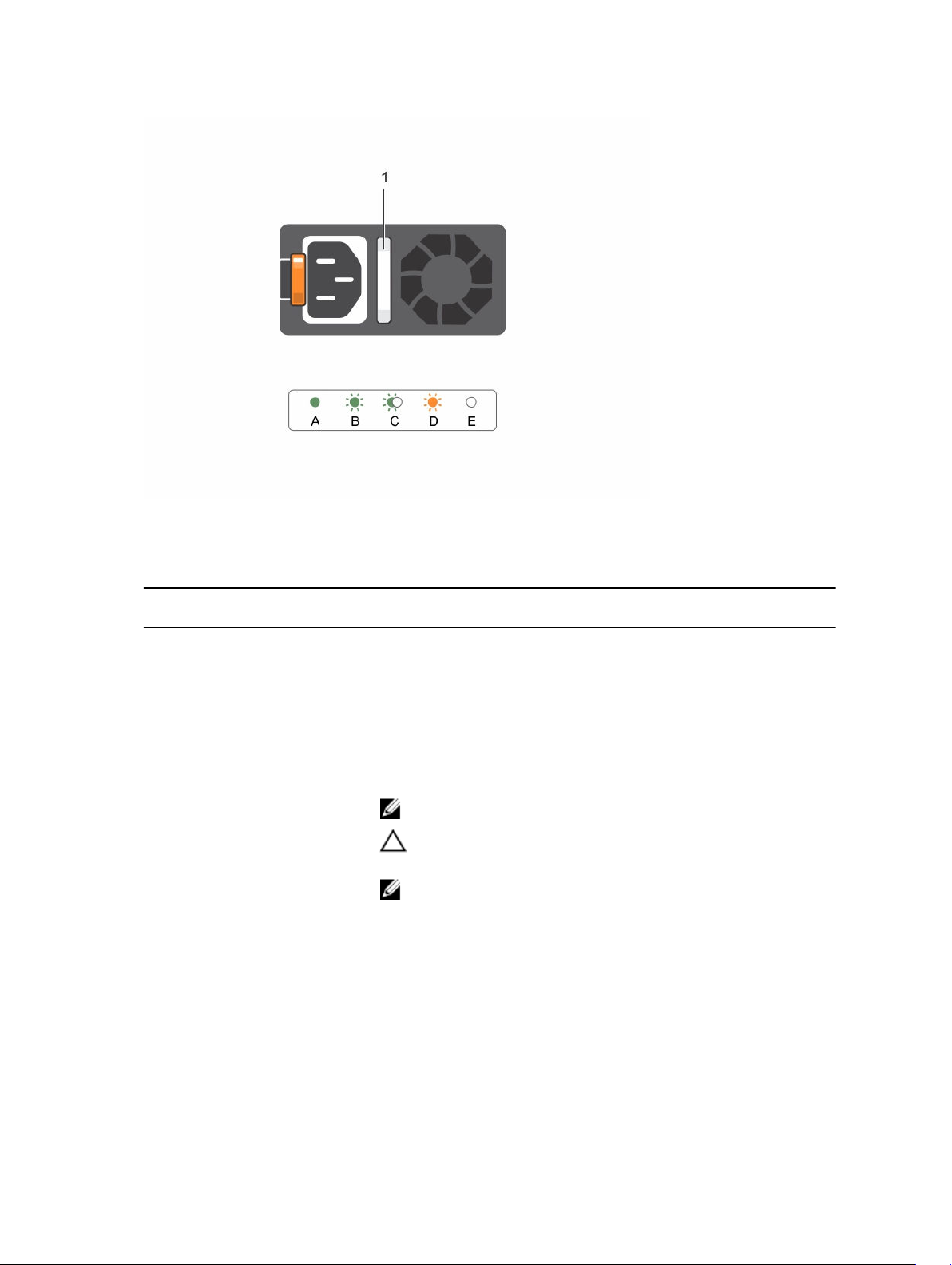
Figure 5. AC PSU status indicator
1. AC PSU status indicator/handle
Table 6. AC PSU status indicators
Convention Power indicator
Condition
pattern
A Green A valid power source is connected to the PSU and the PSU is
operational.
B Flashing green When the firmware of the PSU is being updated, the PSU handle
flashes green.
C Flashing green
and turns off
When hot-adding a PSU, the PSU handle flashes green five times at
4 Hz rate and turns off. This indicates a PSU mismatch with respect
to efficiency, feature set, health status, and supported voltage.
NOTE: Ensure that both the PSUs are of the same capacity.
CAUTION: For AC PSUs, use only PSUs with the Extended
Power Performance (EPP) label on the back.
NOTE: Mixing PSUs from previous generations of Dell
PowerEdge servers can result in a PSU mismatch condition or
failure to turn the system on.
D Flashing amber Indicates a problem with the PSU.
15
Page 16
Convention Power indicator
pattern
E Not lit Power is not connected.
Condition
CAUTION: When correcting a PSU mismatch, replace only the
PSU with the flashing indicator. Swapping the PSU to make a
matched pair can result in an error condition and unexpected
system shutdown. To change from a high output
configuration to a low output configuration or vice versa, you
must turn off the system.
CAUTION: AC PSUs support both 220 V and 110 V input
voltages with the exception of Titanium PSUs, which support
only 220 V. When two identical PSUs receive different input
voltages, they can output different wattages, and trigger a
mismatch.
CAUTION: If two PSUs are used, they must be of the same type
and have the same maximum output power.
CAUTION: Combining AC and DC PSUs is not supported and
triggers a mismatch.
GUID-B78FC6EE-0A44-41A9-B7BB-18B2285C2528
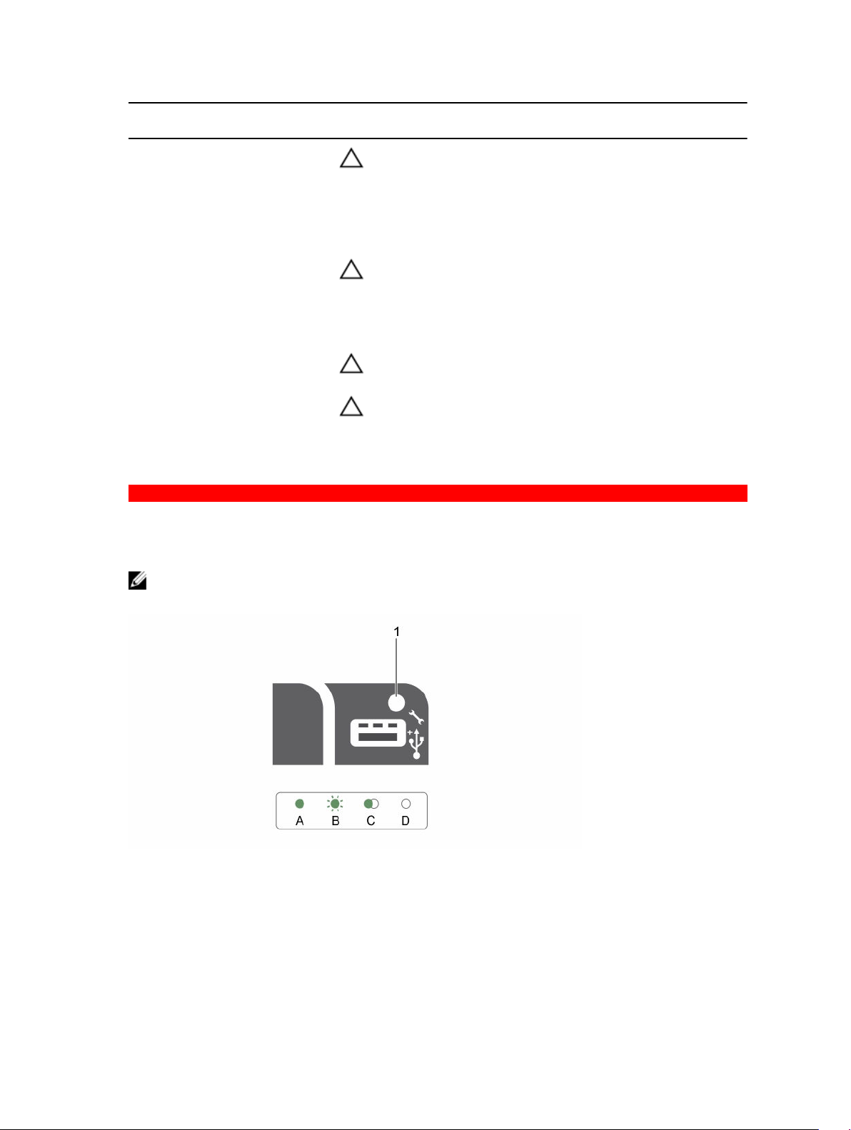
iDRAC Direct LED indicator codes
The iDRAC Direct LED indicator lights up to indicate that the port is connected and is being used as a part
of the iDRAC subsystem.
NOTE: The iDRAC Direct LED indicator does not turn on when the USB port is used in the USB
mode.
Figure 6. iDRAC Direct LED indicator
1. iDRAC Direct status indicator
The iDRAC Direct LED indicator table describes iDRAC Direct activity when configuring iDRAC Direct by
using the management port (USB XML Import).
16
Page 17
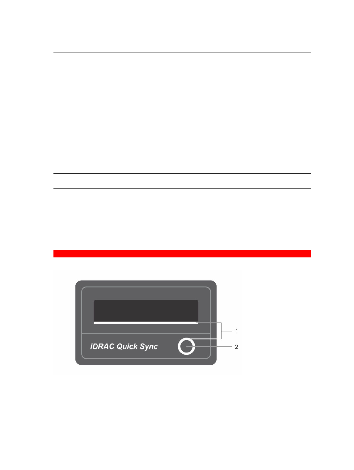
Table 7. iDRAC Direct LED indicators
Convention iDRAC Direct
A Green Turns green for a minimum of two seconds to indicate the start and
B Flashing green Indicates file transfer or any operation tasks.
C Green and turns
D Not lit Indicates that the USB is ready to be removed or that a task is
The following table describes iDRAC Direct activity when configuring iDRAC Direct by using your laptop
and cable (Laptop Connect):
Table 8. iDRAC Direct LED indicator patterns
iDRAC Direct LED
indicator pattern
Solid green for two
seconds
Flashing green (on
for two seconds and
off for two seconds)
LED indicator
pattern
off
Condition
Indicates that the laptop is connected.
Indicates that the laptop connected is recognized.
Condition
end of a file transfer.
Indicates that the file transfer is complete.
complete.
Turns off Indicates that the laptop is unplugged.
GUID-E6AEA86E-2362-4E9A-BCF2-1167A370E966
Quick Sync indicator codes
Figure 7. Quick Sync
1. Quick Sync Status Indicator 2. Quick Sync Activation Button
17
Page 18

Table 9. Quick Sync indicator codes
Quick Sync
indicator pattern
Slow blink Quick Sync is waiting to be configured from iDRAC.
Solid Quick Sync is ready to transfer.
Blinks three times
rapidly and then
turns off
Blinks continuously
when the mobile
device touches
antenna
Blinks rapidly
continuously when
the activation button
is pressed
Turns off Indicates that the Quick Sync feature is turned off. Use the activation button to
Condition
Quick Sync feature is disabled from iDRAC.
Indicates data transfer activity.
Quick Sync hardware is not responding properly.
activate it. If pressing the activation button does not turn on the LEDs, it indicates
that power is not delivered to the Quick Sync bezel.
GUID-86B603BB-113C-45E2-B765-11AA1C626BE2
Locating Service Tag of your system
Your system is identified by a unique Express Service Code and Service Tag number. The Express Service
Code and Service Tag are found on the front of the system by pulling out the information tag.
Alternatively, the information may be on a sticker on the chassis of the system. This information is used
by Dell to route support calls to the appropriate personnel.
GUID-FFD1DBDF-FE27-4F74-B422-AC3614907ADC
Documentation matrix
The documentation matrix describes documents for setting up and managing your system.
Table 10. Documentation matrix
To... Refer to...
Install your system into a rack Rack documentation included with your rack
solution.
Set up your system and know the system technical
specifications
Set up your Dell DR Series system Setting up your Dell DR4300 system that shipped
Troubleshoot the system and install or replace
system components
Getting Started With Your System that shipped with
your system or see Dell.com/support/home
with your system or see Dell.com/support/home
Dell DR4300 System Owner’s Manual at Dell.com/
support/home
18
Page 19

To... Refer to...
Manage DR Series system data backup and
replication operations
Know the latest information about new features
and known issues with a specific product release.
Gather information about supported hardware and
software versions for the Dell DR Series system.
Deploy the virtual DR2000v system on supported
virtual platforms.
Configure, manage, update, and restore the system Dell DR Series System Administrator Guide at
Install the operating system Operating system documentation at Dell.com/
Get an overview of the Dell Systems Management
offerings
Configure and log in to iDRAC, set up managed
and management system, know the iDRAC
features and troubleshoot using iDRAC
Know about the RACADM subcommands and
supported RACADM interfaces
Launch, enable and disable Lifecycle Controller,
know the features, use and troubleshoot Lifecycle
Controller
Dell DR Series System Command Line Reference
Guide at Dell.com/support/home
Dell DR Series System Release Notes at Dell.com/
support/home
Dell DR Series System Interoperability Guide at
Dell.com/support/home
Dell DR2000v Deployment Guide at Dell.com/
support/home
Dell.com/support/home
operatingsystemmanuals
Dell OpenManage Systems Management Overview
Guideat Dell.com/openmanagemanuals
Integrated Dell Remote Access Controller User's
Guide at Dell.com/esmmanuals
RACADM Command Line Reference Guide for
iDRAC and CMC at Dell.com/esmmanuals
Dell Lifecycle Controller User’s Guide at Dell.com/
esmmanuals
Use Lifecycle Controller Remote Services Dell Lifecycle Controller Remote Services Quick
Start Guide at Dell.com/esmmanuals
Set up, use, and troubleshoot OpenManage Server
Administrator
Install, use, and troubleshoot OpenManage
Essentials
Know the features of the storage controller cards,
deploy the cards, and manage the storage
subsystem
Check the event and error messages generated by
the system firmware and agents that monitor
system components
Dell OpenManage Server Administrator User’s
Guide at Dell.com/openmanagemanuals
Dell OpenManage Essentials User’s Guide at
Dell.com/openmanagemanuals
Storage controller documentation at Dell.com/
storagecontrollermanuals
Dell Event and Error Messages Reference Guide at
Dell.com/esmmanuals
19
Page 20
GUID-C32A42E1-FBC4-4DFE-983D-DF4D34FF1E17
Technical specifications
The technical and environmental specifications of your system are outlined in this section.
GUID-DAD8F503-360C-424D-8629-744021A098FD
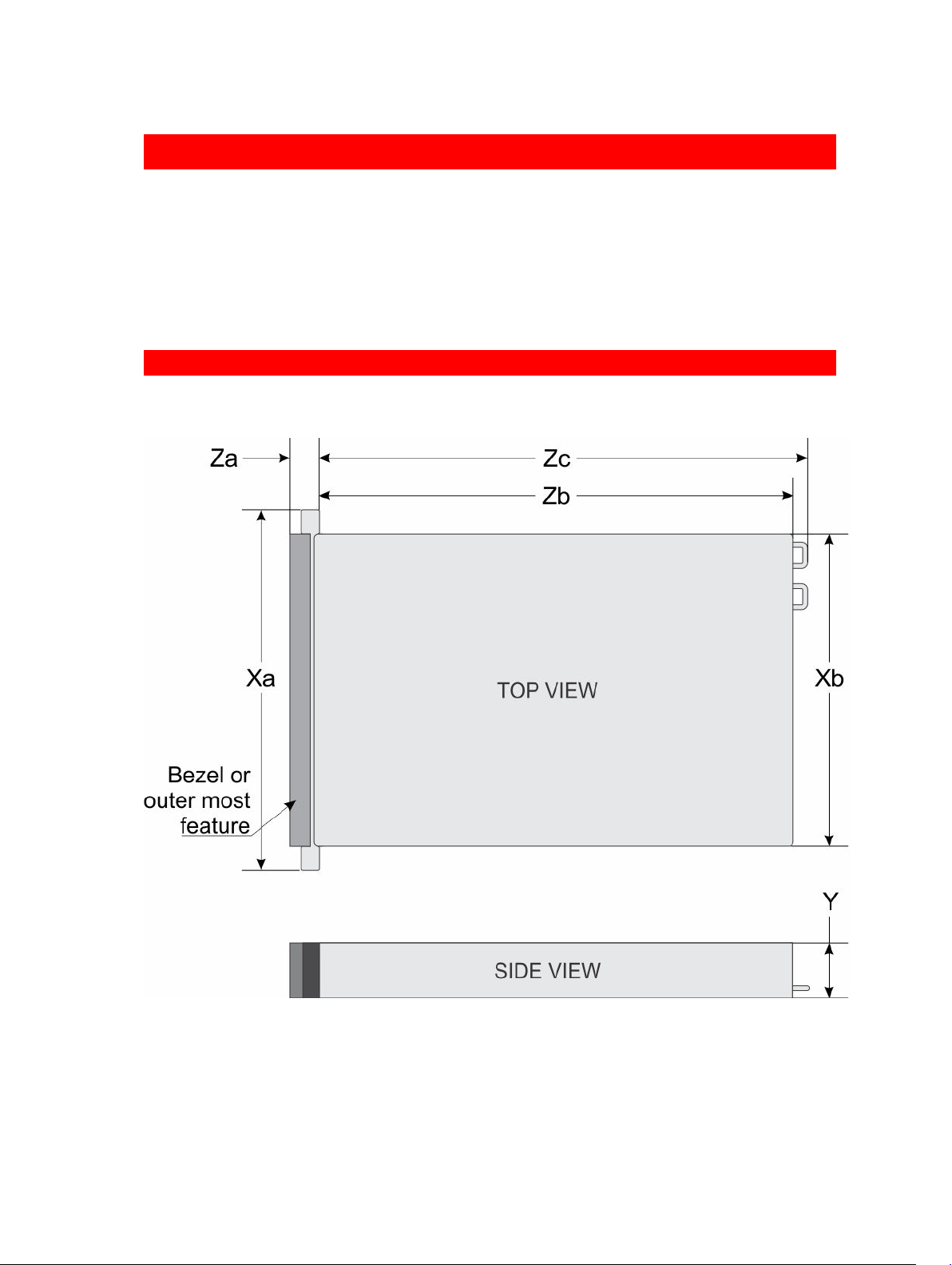
Chassis dimensions
This section describes the physical dimensions of the system.
2
Figure 8. Chassis dimensions of your Dell DR4300 system
20
Page 21

Table 11. Dimensions of your system
Xa Xb Y Za (with
bezel)
482.4 mm 444.0 mm 87.3 mm 32.0 mm 18.0 mm 684.0 mm 723.0 mm
GUID-B429B4B3-3016-4A6B-91C0-CBE0F764946D
Za (without
bezel)
Zb Zc
Chassis weight
This section describes the weight of the system.
Table 12. Chassis weight
System Maximum weight (with all hard drives/SSDs)
Dell DR4300 system
GUID-2E54BA35-C422-4BEC-A114-F4CF22629D2C
36.5 kg (80.47 lb) (3.5-inch hard drive systems)
Processor specifications
Your Dell DR4300 system supports up to two Intel Xeon E5-2660 v3 processors.
GUID-E19E3355-2518-4654-ABB9-E26B6DE08C0B
PSU specifications
Your Dell DR4300 system supports up to two AC redundant power supply units (PSUs).
Table 13. PSU specifications
PSU Class Heat dissipation
(maximum)
1100 W AC Platinum 4100 BTU/hr 50/60 Hz 100–240 V AC, autoranging
NOTE: Heat dissipation is calculated using the PSU wattage rating.
NOTE: This system is also designed to connect to the IT power systems with a phase to phase
voltage not exceeding 230 V.
GUID-80981FD0-DC12-475E-A81A-7940257A5073
Frequency Voltage
System battery specifications
Your Dell DR4300 system supports CR 2032 3.0-V lithium coin cell system battery.
GUID-C04536D8-DE35-4638-A947-5000BBE5A816
Expansion bus specifications
The Dell DR4300 system supports PCI express (PCIe) generation 3 expansion cards, which need to be
installed on the system board using expansion card risers. This system supports three types of expansion
card risers. The following table provides the expansion card riser specifications:
21
Page 22

Table 14. Expansion card riser specifications
Expansion card riser PCIe slots on the
riser
Riser 1 Slot 1 half-height low-profile x8
Riser 1 Slot 2 half-height low-profile x8
Riser 1 Slot 3 half-height low-profile x8
Riser 2 Slot 4 full-height full-length x16
Riser 2 Slot 5 full-height full-length x8
Riser 3 (alternate) Slot 6 full-height full-length x16
NOTE: When using slots 1 through 4 on the riser, ensure that both the processors are installed on
the system.
Height Length Link
GUID-B57167F2-1DB9-4283-A315-3F094CEC131D
Memory specifications
The Dell DR4300 system supports DDR4 registered DIMMs (RDIMMs). Supported memory bus
frequencies are 1333MT/s, 1600 MT/s, 1866 MT/s, 2133MT/s, or 2400 MT/s.
Table 15. Memory specifications
Memory module
sockets
Twenty-four 288–
pin
Memory capacity Minimum RAM Maximum RAM
4 GB single-ranked or 8
GB dual-ranked RDIMMs
• 4 GB with single
processor
• 8 GB with dual
processors (minimum
one memory module
per processor)
64 GB with two
processors
GUID-40E1EAB7-5862-41D4-844D-91B0F2C2D1D7
Drive specifications
GUID-092E5133-B62C-448C-8552-7729CD2C224D
Hard drives
The Dell DR4300 system supports up to twelve 3.5-inch hard drives and two optional 2.5-inch backaccessible SAS, SATA, or Nearline SAS hard drives.
GUID-35EC5EFB-160A-4A43-A66D-EB5D10AF35DC
Ports and connectors specifications
GUID-B915F181-8D3E-443A-A876-7F350AD542ED
USB ports
The Dell DR4300 system supports:
22
Page 23

• USB 2.0-compliant ports on the front panel
• USB 3.0-complaint ports on the back panel
• internal USB 3.0-compliant port
The following table provides more information about the USB specifications:
Table 16. USB specifications
System Front panel Back panel Internal
Dell DR4300 system One USB management
port/iDRAC Direct
Two 9-pin, USB 3.0compliant ports
One 9-pin, USB 3.0compliant port
GUID-77EE3578-9A39-4A61-806C-03E3D4C9772D
NIC ports
The Dell DR4300 system supports four Network Interface Controller (NIC) ports on the back panel, which
is available in one of the following three NIC configurations:
• Four 1 Gbps
• Two 1 Gbps and two 10 Gbps
• Four 10 Gbps
GUID-7EAFB060-2567-408C-8B4B-236D5D99A1BF
Serial connector
The serial connector connects a serial device to the system. The Dell DR4300 system supports one serial
connector on the back panel, which is a 9-pin connector, Data Terminal Equipment (DTE), 16550compliant.
GUID-5025B7F3-BD6E-4CC0-B5FD-A0FD0AC79699
VGA ports
The Video Graphic Array (VGA) port enables you to connect the system to a VGA display. The Dell
DR4300 system supports two 15-pin VGA ports on the front and back panels.
GUID-EF3DF67A-48FA-4274-AC4B-DC2BD158D7AB
Internal Dual SD Module
The Dell DR4300 system supports two optional flash memory card slots with an internal dual SD module.
NOTE: One card slot is dedicated for redundancy.
GUID-6772BAF8-05FD-45C6-86A1-B05A51B6CA34
Video specifications
The Dell DR4300 system supports Matrox G200eR2 graphics card with 16 MB capacity.
23
Page 24

GUID-D7F97497-B916-4E1A-92BD-F7DE5A5521A9
Environmental specifications
NOTE: For additional information about environmental measurements for specific system
configurations, see Dell.com/environmental_datasheets.
Table 17. Temperature specifications
Temperature Specifications
Storage –40°C to 65°C (–40°F to 149°F)
Continuous operation (for altitude less than
950 m or 3117 ft)
Fresh air For information about fresh air, see Expanded Operating
Maximum temperature gradient (operating
and storage)
Table 18. Relative humidity specifications
Relative humidity Specifications
Storage 5% to 95% RH with 33°C (91°F) maximum dew point.
Operating 10% to 80% relative humidity with 29°C (84.2°F) maximum
Table 19. Maximum vibration specifications
Maximum vibration Specifications
Operating 0.26 G
Storage 1.88 G
10°C to 35°C (50°F to 95°F) with no direct sunlight on the
equipment.
Temperature section.
20°C/h (68°F/h)
Atmosphere must be non-condensing at all times.
dew point.
at 5 Hz to 350 Hz (all operation orientations).
rms
at 10 Hz to 500 Hz for 15 min (all six sides
rms
tested).
Table 20. Maximum shock specifications
Maximum vibration Specifications
Operating Six consecutively executed shock pulses in the positive
and negative x, y, and z axes of 40 G for up to 2.3 ms.
Storage Six consecutively executed shock pulses in the positive
and negative x, y, and z axes (one pulse on each side of
the system) of 71 G for up to 2 ms.
24
Page 25

Table 21. Maximum altitude specifications
Maximum altitude Specifications
Operating
Storage 12,000 m (39,370 ft)
Table 22. Operating temperature de-rating specifications
Operating temperature de-rating Specifications
Up to 35°C (95°F) Maximum temperature is reduced by 1°C/300 m (1°F/547
35°C to 40°C (95°F to 104°F) Maximum temperature is reduced by 1°C/175 m (1°F/319
40°C to 45°C (104°F to 113°F) Maximum temperature is reduced by 1°C/125 m (1°F/228
3048 m (10,000 ft)
ft) above 950 m (3,117 ft).
ft) above 950 m (3,117 ft).
ft) above 950 m (3,117 ft).
GUID-D54FD9A9-2561-4FFB-A078-61004DA51657
Particulate and gaseous contamination specifications
The following table defines the limitations that help avoid any equipment damage or failure from
particulates and gaseous contamination. If the levels of particulates or gaseous pollution exceed the
specified limitations and result in equipment damage or failure, you may need to rectify the
environmental conditions. Re-mediation of environmental conditions is the responsibility of the
customer.
Table 23. Particulate contamination specifications
Particulate contamination Specifications
Air filtration Data center air filtration as defined by ISO Class 8 per ISO
14644-1 with a 95% upper confidence limit.
NOTE: This condition applies to data center
environments only. Air filtration requirements do not
apply to IT equipment designed to be used outside a
data center, in environments such as an office or
factory floor.
NOTE: Air entering the data center must have
MERV11 or MERV13 filtration.
Conductive dust Air must be free of conductive dust, zinc whiskers, or
other conductive particles.
NOTE: This condition applies to data center and
non-data center environments.
Corrosive dust
• Air must be free of corrosive dust.
• Residual dust present in the air must have a
deliquescent point less than 60% relative humidity.
25
Page 26

Particulate contamination Specifications
NOTE: This condition applies to data center and
non-data center environments.
Table 24. Gaseous contamination specifications
Gaseous contamination Specifications
Copper coupon corrosion rate <300 Å/month per Class G1 as defined by ANSI/
ISA71.04-1985.
Silver coupon corrosion rate <200 Å/month as defined by AHSRAE TC9.9.
NOTE: Maximum corrosive contaminant levels measured at ≤50% relative humidity.
GUID-C5C1A8E6-C380-46EA-A788-604FD8778370
Standard operating temperature
Table 25. Standard operating temperature specifications
Standard operating temperature Specifications
Continuous operation (for altitude less than
950 m or 3117 ft)
10°C to 35°C (50°F to 95°F) with no direct sunlight on the
equipment.
GUID-E8CDC6EA-0355-4E26-8C90-8FD8741EC068
Expanded operating temperature
Table 26. Expanded operating temperature specifications
Expanded operating temperature Specifications
Continuous operation 5°C to 40°C at 5% to 85% RH with 29°C dew point.
NOTE: Outside the standard operating temperature
(10°C to 35°C), the system can operate continuously
in temperatures as low as 5°C and as high as 40°C.
For temperatures between 35°C and 40°C, de-rate
maximum allowable temperature by 1°C per 175 m above
950 m (1°F per 319 ft).
≤ 1% of annual operating hours –5°C to 45°C at 5% to 90% RH with 29°C dew point.
NOTE: Outside the standard operating temperature
(10°C to 35°C), the system can operate down to –5°C
or up to 45°C for a maximum of 1% of its annual
operating hours.
For temperatures between 40°C and 45°C, de-rate
maximum allowable temperature by 1°C per 125 m above
950 m (1°F per 228 ft).
NOTE: When operating in the expanded temperature range, system performance may be impacted.
26
Page 27

NOTE: When operating in the expanded temperature range, ambient temperature warnings maybe
reported on the LCD panel and in the System Event Log.
GUID-C7ED6A84-6734-4315-B167-92B007911598
Expanded operating temperature restrictions
• Do not perform a cold startup below 5°C.
• The operating temperature specified is for a maximum altitude of 3050 m (10,000 ft).
• 160 W or higher wattage processor is not supported.
• Redundant power supply units are required.
• Non-Dell qualified peripheral cards and/or peripheral cards greater than 25 W are not supported.
• The 3.5-inch hard drive chassis supports a maximum of 120 W processor.
• The 2.5-inch hard drive chassis supports a maximum of 145 W processor.
• Only SSDs are allowed in the hard drive slots at the back of the 3.5-inch hard drive chassis.
• Mid drive configurations, eight 3.5-inch and eighteen 1.8-inch SSD configurations are not supported.
• GPU is not supported
• Tape backup unit (TBU) is not supported.
27
Page 28

GUID-5748796D-6E9F-4449-ABF4-8D669F585840
Initial system setup and configuration
GUID-12906D3A-32E6-44A6-BF6E-3E4B1E522C3C
Setting up your system
Complete the following steps to set up your system:
1. Unpack the system.
2. Install the system into the rack. For more information about installing the system into the rack, see
your system Rack Installation Placemat at Dell.com/poweredgemanuals.
3. Connect the peripherals to the system.
4. Connect the system to its electrical outlet.
5. Turn the system on by pressing the power button or by using iDRAC.
6. Turn on the attached peripherals.
GUID-B7DABD59-D2F1-46E4-9022-6314E97E19D3
3
iDRAC configuration
The Integrated Dell Remote Access Controller (iDRAC) is designed to make system administrators more
productive and improve the overall availability of Dell systems. iDRAC alerts administrators to system
issues, helps them perform remote system management, and reduces the need for physical access to the
system.
GUID-F24BAF10-1283-44A5-8E2E-AE1A076D14A8
Options to set up iDRAC IP address
You must configure the initial network settings based on your network infrastructure to enable the
communication to and from iDRAC. You can set up the IP address by using one of the following
interfaces:
Interfaces Document/Section
iDRAC Settings
utility
Dell Deployment
Toolkit
Dell Lifecycle
Controller
Chassis or Server
LCD panel
See Dell Integrated Dell Remote Access Controller User's Guide at Dell.com/
idracmanuals
See Dell Deployment Toolkit User’s Guide at Dell.com/openmanagemanuals
See Dell Lifecycle Controller User’s Guide at Dell.com/idracmanuals
See the LCD panel section
28
Page 29

You must use the default iDRAC IP address 192.168.0.120 to configure the initial network settings,
including setting up DHCP or a static IP for iDRAC.
NOTE: To access iDRAC, ensure that you install the iDRAC port card or connect the network cable
to the Ethernet connector 1 on the system board.
NOTE: Ensure that you change the default user name and password after setting up the iDRAC IP
address.
GUID-630530B1-28EB-4BC1-BFB0-BA34E4EF576B
Log in to iDRAC
You can log in to iDRAC as:
• iDRAC user
• Microsoft Active Directory user
• Lightweight Directory Access Protocol (LDAP) user
The default user name and password are root and calvin. You can also log in by using Single Sign-On
or Smart Card.
NOTE: You must have iDRAC credentials to log in to iDRAC.
For more information about logging in to iDRAC and iDRAC licenses, see the Integrated Dell Remote
Access Controller User's Guide at Dell.com/idracmanuals.
GUID-1AB8E7C1-D279-4356-B543-698D5F784858
Options to install the operating system
If the system is shipped without an operating system, install the supported operating system by using one
of the following resources:
Table 27. Resources to install the operating system
Resources Location
Dell Systems Management Tools and
Documentation media
Dell Lifecycle Controller Dell.com/idracmanuals
Dell OpenManage Deployment Toolkit Dell.com/openmanagemanuals
Dell certified VMware ESXi Dell.com/virtualizationsolutions
Supported operating systems on Dell PowerEdge
systems
Installation and How-to videos for supported
operating systems on Dell PowerEdge systems
GUID-49D232C7-0B7A-4536-B5A0-1629CAACDA0F
Methods to download firmware and drivers
You can download the firmware and drivers by using any of the following methods:
Dell.com/operatingsystemmanuals
Dell.com/ossupport
Supported Operating Systems for Dell PowerEdge
Systems
29
Page 30

Table 28. Firmware and drivers
Methods Location
From the Dell Support site Dell.com/support/home
Using Dell Remote Access Controller Lifecycle
Controller (iDRAC with LC)
Using Dell Repository Manager (DRM) Dell.com/openmanagemanuals
Using Dell OpenManage Essentials (OME) Dell.com/openmanagemanuals
Using Dell Server Update Utility (SUU) Dell.com/openmanagemanuals
Using Dell OpenManage Deployment Toolkit (DTK) Dell.com/openmanagemanuals
Dell.com/idracmanuals
GUID-7E37E631-1D4B-4162-AE45-51D94A295730
Downloading the drivers and firmware
Dell recommends that you download and install the latest BIOS, drivers, and systems management
firmware on your system.
Prerequisites
Ensure that you clear the web browser cache before downloading the drivers and firmware.
Steps
1. Go to Dell.com/support/drivers.
2. Under the Drivers & Downloads section, type the Service Tag of your system in the Service Tag or
Express Service Code box.
NOTE: If you do not have the Service Tag, select Detect My Product to allow the system to
automatically detect your Service Tag, or under General support, navigate to your product.
3. Click Drivers & Downloads.
The drivers that are applicable to your selection are displayed.
4. Download the drivers you need to a USB drive, CD, or DVD.
GUID-58C4DFD1-B6F9-484E-996A-5421DA3F325B
Manage your system
This section provides the information about server management software.
Server
Management
Software
OpenManage
OpenManage
Essentials
30
Description
The Dell OpenManage Server Administrator provides a comprehensive one-to-one
systems management solution for both local and remote servers and their storage
controllers and Direct Attached Storage (DAS).
For information about OpenManage documents, see Dell.com/
openmanagemanuals.
Dell OpenManage Essentials is the newest one-to-many management console for
managing Dell PowerEdge servers and direct-attached storage as it provides a
Page 31

Server
Management
Software
Description
simple and easy interface for system administrators to maximize the uptime and
health of Dell systems.
For information about OpenManage documents, see Dell.com/
openmanagemanuals.
Remote Access
Controller with
Dell Lifecycle
Controller (iDRAC
with LC)
Partner Programs
Enterprise Systems
Management
OpenManage
Connections
Client Systems
Management
iDRAC with Dell Lifecycle Controller allows administrators to deploy, update,
monitor, and manage Dell servers from any location without the use of agents in a
one-to-one or one-to-many method. This out-of-band management allows the
updates to be sent from Dell or appropriate third-party consoles directly to iDRAC
with Dell Lifecycle Controller on a Dell PowerEdge server, regardless of the
operating system that may or may not be running.
For information about Remote Enterprise Systems Management documents, see
Dell.com/idracmanuals.
For information about OpenManage Connections Enterprise Systems Management
documents, see Dell.com/omconnectionsenterprisesystemsmanagement.
For information about OpenManage Connections Client Systems Management
documents, see Dell.com/dellclientcommandsuitemanuals.
31
Page 32

GUID-B87B3D21-E8ED-4C2B-A4B2-41206935DB10
Pre-operating system management applications
You can manage basic settings and features of a system without booting to the operating system by
using the system firmware.
GUID-2C97B129-2402-4B05-A77D-F35B679E7E1A
Options to manage the pre-operating system applications
Your system has the following options to manage the pre-operating system applications:
• System Setup
• Boot Manager
• Dell Lifecycle Controller
• Preboot Execution Environment (PXE)
4
Related Links
System Setup
Boot Manager
Dell Lifecycle Controller
PXE boot
GUID-14F9A24F-3F4E-4510-BAD1-7DF47F366F2A
System Setup
By using the System Setup screen, you can configure the BIOS settings, iDRAC settings, and device
settings of your system.
NOTE: Help text for the selected field is displayed in the graphical browser by default. To view the
help text in the text browser, press F1.
You can access system setup by using two methods:
• Standard graphical browser — The browser is enabled by default.
• Text browser — The browser is enabled by using Console Redirection.
Related Links
System Setup details
Viewing System Setup
32
Page 33

GUID-2BB81115-5C50-4E95-9D7B-E438D948FA28
Viewing System Setup
To view the System Setup screen, perform the following steps:
1. Turn on, or restart your system.
2. Press F2 immediately after you see the following message:
F2 = System Setup
NOTE: If your operating system begins to load before you press F2, wait for the system to finish
booting, and then restart your system and try again.
Related Links
System Setup
System Setup details
GUID-4A2E1A19-F95D-465A-B120-A108D894BC68
System Setup details
The System Setup Main Menu screen details are explained as follows:
Option Description
System BIOS Enables you to configure BIOS settings.
iDRAC Settings Enables you to configure iDRAC settings.
The iDRAC settings utility is an interface to set up and configure the iDRAC
parameters by using UEFI (Unified Extensible Firmware Interface). You can enable
or disable various iDRAC parameters by using the iDRAC settings utility. For more
information about this utility, see Integrated Dell Remote Access Controller User’s
Guide at Dell.com/idracmanuals.
Device Settings Enables you to configure device settings.
Related Links
System Setup
Viewing System Setup
33
Page 34

GUID-35CD97BF-2FD5-4CCF-8DC1-E7FA89CA394F
System BIOS
You can use the System BIOS screen to edit specific functions such as boot order, system password,
setup password, set the RAID mode, and enable or disable USB ports.
Related Links
System BIOS Settings details
Boot Settings
Network Settings
System Information
Memory Settings
Processor Settings
SATA Settings
Integrated Devices
Serial Communication
System Profile Settings
Miscellaneous Settings
iDRAC Settings utility
Device Settings
Secure Boot Custom Policy Settings
Viewing System BIOS
GUID-2F682B1C-8996-4D8A-9C83-56E13EDA6F4A
Viewing System BIOS
To view the System BIOS screen, perform the following steps:
1. Turn on, or restart your system.
2. Press F2 immediately after you see the following message:
F2 = System Setup
NOTE: If your operating system begins to load before you press F2, wait for the system to finish
booting, and then restart your system and try again.
3. On the System Setup Main Menu screen, click System BIOS.
Related Links
System BIOS
System BIOS Settings details
GUID-5E09EEBE-3FEC-4D46-8D4F-25AC0A5765E3
System BIOS Settings details
The System BIOS Settings screen details are explained as follows:
Option
System
Information
Memory Settings Specifies information and options related to the installed memory.
Processor Settings Specifies information and options related to the processor such as speed and
Description
Specifies information about the system such as the system model name, BIOS
version, and Service Tag.
cache size.
34
Page 35

Option Description
SATA Settings Specifies options to enable or disable the integrated SATA controller and ports.
Boot Settings Specifies options to specify the boot mode (BIOS or UEFI). Enables you to modify
UEFI and BIOS boot settings.
Network Settings Specifies options to change the network settings.
Integrated
Devices
Serial
Communication
System Profile
Settings
System Security Specifies options to configure the system security settings, such as system
Miscellaneous
Settings
Related Links
System BIOS
Viewing System BIOS
GUID-9F5AF39D-242E-479C-81B5-AA92E8BEE63B
Boot Settings
You can use the Boot Settings screen to set the boot mode to either BIOS or UEFI. It also enables you to
specify the boot order.
Related Links
Boot Settings details
System BIOS
Viewing Boot Settings
Choosing the system boot mode
Changing the boot order
Specifies options to manage integrated device controllers and ports and specify
related features and options.
Specifies options to manage the serial ports and specify related features and
options.
Specifies options to change the processor power management settings, memory
frequency, and so on.
password, setup password, Trusted Platform Module (TPM) security. It also
manages the power and NMI buttons on the system.
Specifies options to change the system date, time, and so on.
GUID-94395C04-ADE7-4BDD-B59F-233605CD7D12
Viewing Boot Settings
To view the Boot Settings screen, perform the following steps:
1. Turn on, or restart your system.
2. Press F2 immediately after you see the following message:
F2 = System Setup
NOTE: If your operating system begins to load before you press F2, wait for the system to finish
booting, and then restart your system and try again.
3. On the System Setup Main Menu screen, click System BIOS.
4. On the System BIOS screen, click Boot Settings.
35
Page 36

Related Links
Boot Settings
Boot Settings details
Choosing the system boot mode
Changing the boot order
GUID-2F825DC7-A22A-482F-BBEC-C2C19FE78781
Boot Settings details
The Boot Settings screen details are explained as follows:
Option Description
Boot Mode Enables you to set the boot mode of the system.
CAUTION: Switching the boot mode may prevent the system from booting if
the operating system is not installed in the same boot mode.
If the operating system supports UEFI, you can set this option to UEFI. Setting this
field to BIOS allows compatibility with non-UEFI operating systems. This option is
set to BIOS by default.
NOTE: Setting this field to UEFI disables the BIOS Boot Settings menu. Setting
this field to
BIOS disables the UEFI Boot Settings menu.
Boot Sequence
Retry
Hard-Disk Failover Specifies the hard drive that is booted in the event of a hard drive failure. The
Boot Option
Settings
BIOS Boot
Settings
UEFI Boot Settings Enables or disables UEFI Boot options. The Boot options include IPv4 PXE and IPv6
Related Links
Boot Settings
Viewing Boot Settings
Choosing the system boot mode
Changing the boot order
Enables or disables the Boot Sequence Retry feature. If this option is set to Enabled
and the system fails to boot, the system reattempts the boot sequence after 30
seconds. This option is set to Enabled by default.
devices are selected in the Hard-Disk Drive Sequence on the Boot Option Setting
menu. When this option is set to Disabled, only the first hard drive in the list is
attempted to boot. When this option is set to Enabled, all hard drives are attempted
to boot in the order selected in the
enabled for UEFI Boot Mode.
Configures the boot sequence and the boot devices.
Enables or disables BIOS boot options.
NOTE: This option is enabled only if the boot mode is BIOS.
PXE. This option is set to IPv4 by default.
NOTE: This option is enabled only if the boot mode is UEFI.
Hard-Disk Drive Sequence. This option is not
GUID-12C950B3-B0EF-4089-867E-89277DB2DA6A
36
Page 37

Choosing the system boot mode
System Setup enables you to specify one of the following boot modes for installing your operating
system:
• BIOS boot mode (the default) is the standard BIOS-level boot interface.
• Unified Extensible Firmware Interface (UEFI) boot mode is an enhanced 64-bit boot interface. If you
have configured your system to boot to UEFI mode, it replaces the system BIOS.
1. From the System Setup Main Menu, click Boot Settings, and select Boot Mode.
2. Select the boot mode you want the system to boot into.
CAUTION: Switching the boot mode may prevent the system from booting if the operating
system is not installed in the same boot mode.
3. After the system boots in the specified boot mode, proceed to install your operating system from
that mode.
NOTE: Operating systems must be UEFI-compatible to be installed from the UEFI boot mode. DOS
and 32-bit operating systems do not support UEFI and can only be installed from the BIOS boot
mode.
NOTE: For the latest information about supported operating systems, go to Dell.com/ossupport.
Related Links
Boot Settings
Boot Settings details
Viewing Boot Settings
GUID-334369A4-CDAE-4C92-852D-BC139AC4CAB0
Changing the boot order
You may have to change the boot order if you want to boot from a USB key. The following instructions
may vary if you have selected BIOS for Boot Mode.
1. On the System Setup Main Menu screen, click System BIOS → Boot Settings.
2. Click Boot Option Settings → Boot Sequence.
3. Use the arrow keys to select a boot device, and use the plus (+) and minus (-) sign keys to move the
device down or up in the order.
4. Click Exit, and then click Yes to save the settings on exit.
Related Links
Boot Settings
Boot Settings details
Viewing Boot Settings
GUID-58701880-7D80-4166-883E-4A38518CF6BC
Network Settings
You can use the Network Settings screen to modify PXE device settings. The network settings option is
available only in the UEFI mode.
NOTE: The BIOS does not control network settings in the BIOS mode. For the BIOS boot mode, the
optional Boot ROM of the network controllers handles the network settings.
37
Page 38

Related Links
UEFI iSCSI Settings
Network Settings screen details
UEFI iSCSI Settings details
System BIOS
Viewing Network Settings
Viewing UEFI iSCSI Settings
GUID-F6F46A55-B0A3-46EF-B2B6-724DDF6664DF
Viewing Network Settings
To view the Network Settings screen, perform the following steps:
1. Turn on, or restart your system.
2. Press F2 immediately after you see the following message:
F2 = System Setup
NOTE: If your operating system begins to load before you press F2, wait for the system to finish
booting, and then restart your system and try again.
3. On the System Setup Main Menu screen, click System BIOS.
4. On the System BIOS screen, click Network Settings.
Related Links
Network Settings
Network Settings screen details
GUID-4DFC3EB0-8100-4AFE-99B9-BCC1A8422070
Network Settings screen details
The Network Settings screen details are explained as follows:
Option
PXE Device n (n =
1 to 4)
PXE Device n
Settings(n = 1 to 4)
Related Links
Network Settings
Viewing Network Settings
Description
Enables or disables the device. When enabled, a UEFI boot option is created for the
device.
Enables you to control the configuration of the PXE device.
GUID-ADC7D625-5C7B-469D-BA9C-4A2C704FCC49
UEFI iSCSI Settings
You can use the iSCSI Settings screen to modify iSCSI device settings. The iSCSI Settings option is
available only in the UEFI boot mode. BIOS does not control network settings in the BIOS boot mode. For
the BIOS boot mode, the option ROM of the network controller handles the network settings.
Related Links
UEFI iSCSI Settings details
Viewing UEFI iSCSI Settings
UEFI iSCSI Settings
Viewing UEFI iSCSI Settings
GUID-F288B290-5373-49C8-B2C5-D565790065F4
38
Page 39

Viewing UEFI iSCSI Settings
To view the UEFI iSCSI Settings screen, perform the following steps:
1. Turn on, or restart your system.
2. Press F2 immediately after you see the following message:
F2 = System Setup
NOTE: If your operating system begins to load before you press F2, wait for the system to finish
booting, and then restart your system and try again.
3. On the System Setup Main Menu screen, click System BIOS.
4. On the System BIOS screen, click Network Settings.
5. On the Network Settings screen, click UEFI iSCSI Settings.
Related Links
UEFI iSCSI Settings
UEFI iSCSI Settings
GUID-B1E50A05-9D94-4C78-A338-BE09860B9A13
UEFI iSCSI Settings details
The UEFI ISCSI Settings screen details are explained as follows:
Option Description
ISCSI Initiator
Name
ISCSI Device n (n =
1 to 4)
Specifies the name of the iSCSI initiator (iqn format).
Enables or disables the iSCSI device. When disabled, a UEFI boot option is created
for the iSCSI device automatically.
GUID-1579708F-42D4-4ADD-A311-68559496D27A
System Security
You can use the System Security screen to perform specific functions such as setting the system
password, setup password and disabling the power button.
Related Links
System Security Settings details
Operating with a setup password enabled
System BIOS
Viewing System Security
Creating a system and setup password
Secure Boot Custom Policy Settings
Using your system password to secure your system
Deleting or changing system and setup password
GUID-4D392CEA-E5CF-4A4D-A1B0-392246978565
Viewing System Security
To view the System Security screen, perform the following steps:
1. Turn on, or restart your system.
2. Press F2 immediately after you see the following message:
F2 = System Setup
NOTE: If your operating system begins to load before you press F2, wait for the system to finish
booting, and then restart your system and try again.
39
Page 40

3. On the System Setup Main Menu screen, click System BIOS.
4. On the System BIOS screen, click System Security.
Related Links
System Security
System Security Settings details
GUID-47D7AC4A-0ECD-49FF-AAF0-2DD1286A7944
System Security Settings details
The System Security Settings screen details are explained as follows:
Option Description
Intel AES-NI Improves the speed of applications by performing encryption and decryption by
using the Advanced Encryption Standard Instruction Set (AES-NI). This option is set
to Enabled by default.
System Password Sets the system password. This option is set to Enabled by default and is read-only
if the password jumper is not installed in the system.
Setup Password Sets the setup password. This option is read-only if the password jumper is not
installed in the system.
Password Status Locks the system password. This option is set to Unlocked by default.
TPM Security
TPM Information Changes the operational state of the TPM. This option is set to No Change by
TPM Status Specifies the TPM status.
TPM Command
Intel TXT Enables or disables the Intel Trusted Execution Technology (TXT) option. To enable
Power Button Enables or disables the power button on the front of the system. This option is set
NMI Button Enables or disables the NMI button on the front of the system. This option is set to
AC Power
Recovery
AC Power
Recovery Delay
User Defined
Delay (60s to
240s)
NOTE: The TPM menu is available only when the TPM module is installed.
Enables you to control the reporting mode of the TPM. The TPM Security option is
set to Off by default. You can only modify the TPM Status, TPM Activation, and Intel
TXT fields if the TPM Status field is set to either On with Pre-boot Measurements
or On without Pre-boot Measurements.
default.
CAUTION: Clearing the TPM results in the loss of all keys in the TPM. The
loss of TPM keys may affect booting to the operating system.
Clears all the contents of the TPM. The TPM Clear option is set to No by default.
the Intel TXT option, virtualization technology and TPM Security must be enabled
with Pre-boot measurements. This option is set to Off by default.
to Enabled by default.
Disabled by default.
Sets how the system behaves after AC power is restored to the system. This option
is set to Last by default.
Sets the time delay for the system to power up after AC power is restored to the
system. This option is set to Immediate by default.
Sets the User Defined Delay option when the User Defined option for AC Power
Recovery Delay is selected.
40
Page 41

Option Description
UEFI Variable
Access
Secure Boot Enables Secure Boot, where the BIOS authenticates each pre-boot image by using
Secure Boot
Policy
Secure Boot
Policy Summary
Related Links
System Security
Viewing System Security
Provides varying degrees of securing UEFI variables. When set to Standard (the
default), UEFI variables are accessible in the operating system per the UEFI
specification. When set to Controlled, selected UEFI variables are protected in the
environment and new UEFI boot entries are forced to be at the end of the current
boot order.
the certificates in the Secure Boot Policy. Secure Boot is disabled by default.
When Secure Boot policy is set to Standard, the BIOS uses the system
manufacturer’s key and certificates to authenticate pre-boot images. When Secure
Boot policy is set to Custom, the BIOS uses the user-defined key and certificates.
Secure Boot policy is set to Standard by default.
Specifies the list of certificates and hashes that secure boot uses to authenticate
images.
GUID-A494ECC4-611F-47BD-B842-5A29B1B7991D
Secure Boot Custom Policy Settings
Secure Boot Custom Policy Settings is displayed only when Secure Boot Policy is set to Custom.
Related Links
Viewing Secure Boot Custom Policy Settings
Secure Boot Custom Policy Settings details
GUID-B37E62BD-932F-41FA-BEAE-5D59CED35342
Viewing Secure Boot Custom Policy Settings
To view the Secure Boot Custom Policy Settings screen, perform the following steps:
1. Turn on, or restart your system.
2. Press F2 immediately after you see the following message:
F2 = System Setup
NOTE: If your operating system begins to load before you press F2, wait for the system to finish
booting, and then restart your system and try again.
3. On the System Setup Main Menu screen, click System BIOS.
4. On the System BIOS screen, click System Security.
5. On the System Security screen, click Secure Boot Custom Policy Settings.
GUID-5A27810F-BDB8-4899-AED3-D4EF4EEE2301
Secure Boot Custom Policy Settings details
The Secure Boot Custom Policy Settings screen details are explained as follows:
Option Description
Platform Key Imports, exports, deletes, or restores the platform key (PK).
Key Exchange Key
Database
Enables you to import, export, delete, or restore entries in the Key Exchange Key
(KEK) Database.
41
Page 42

Option Description
Authorized
Signature
Database
Forbidden
Signature
Database
Imports, exports, deletes, or restores entries in the Authorized Signature Database
(db).
Imports, exports, deletes, or restores entries in the Forbidden Signature Database
(dbx).
GUID-2D52DB49-EA19-4039-9646-CE68A05A6501
Creating a system and setup password
Prerequisites
Ensure that the password jumper is enabled. The password jumper enables or disables the system
password and setup password features. For more information, see the System board jumper settings
section.
NOTE: If the password jumper setting is disabled, the existing system password and setup password
are deleted and you need not provide the system password to boot the system.
Steps
1. To enter System Setup, press F2 immediately after turning on or rebooting your system.
On the System Setup Main Menu screen, click System BIOS → System Security.
2.
3. On the System Security screen, verify that Password Status is set to Unlocked.
4. In the System Password field, type your system password, and press Enter or Tab.
Use the following guidelines to assign the system password:
• A password can have up to 32 characters.
• The password can contain the numbers 0 through 9.
• Only the following special characters are allowed: space, (”), (+), (,), (-), (.), (/), (;), ([), (\), (]), (`).
A message prompts you to reenter the system password.
5. Reenter the system password, and click OK.
6. In the Setup Password field, type your setup password and press Enter or Tab.
A message prompts you to reenter the setup password.
7. Reenter the setup password, and click OK.
8. Press Esc to return to the System BIOS screen. Press Esc again.
A message prompts you to save the changes.
NOTE: Password protection does not take effect until the system reboots.
Related Links
System Security
GUID-E4B2DF0F-A14A-44FD-880E-BBDB6CD7F72D
Using your system password to secure your system
If you have assigned a setup password, the system accepts your setup password as an alternate system
password.
Steps
1. Turn on or reboot your system.
2. Type the system password and press Enter.
42
Page 43

Next steps
When Password Status is set to Locked, type the system password and press Enter when prompted at
reboot.
NOTE: If an incorrect system password is typed, the system displays a message and prompts you to
reenter your password. You have three attempts to type the correct password. After the third
unsuccessful attempt, the system displays an error message that the system has stopped
functioning and must be turned off. Even after you turn off and restart the system, the error
message is displayed until the correct password is entered.
Related Links
System Security
GUID-E60E41C8-6512-4D01-82C5-15CAE87DEB42
Deleting or changing system and setup password
Prerequisites
NOTE: You cannot delete or change an existing system or setup password if the Password Status is
set to Locked.
Steps
1. To enter System Setup, press F2 immediately after turning on or restarting your system.
2. On the System Setup Main Menu screen, click System BIOS → System Security.
3. On the System Security screen, ensure that Password Status is set to Unlocked.
4. In the System Password field, alter or delete the existing system password, and then press Enter or
Tab.
5. In the Setup Password field, alter or delete the existing setup password, and then press Enter or Tab.
If you change the system and setup password, a message prompts you to reenter the new password.
If you delete the system and setup password, a message prompts you to confirm the deletion.
6. Press Esc to return to the System BIOS screen. Press Esc again, and a message prompts you to save
the changes.
Related Links
System Security
GUID-FE3B97ED-EBAD-48E9-9F6B-E0F6993D18D2
Operating with a setup password enabled
If Setup Password is set to Enabled, type the correct setup password before modifying the system setup
options.
If you do not type the correct password in three attempts, the system displays the following message:
Invalid Password! Number of unsuccessful password attempts: <x> System Halted!
Must power down.
Even after you turn off and restart the system, the error message is displayed until the correct password is
typed. The following options are exceptions:
• If System Password is not set to Enabled and is not locked through the Password Status option, you
can assign a system password. For more information, see the System Security Settings screen section.
• You cannot disable or change an existing system password.
NOTE: You can use the password status option with the setup password option to protect the
system password from unauthorized changes.
43
Page 44

Related Links
System Security
GUID-3B8E4DC7-A04C-45F7-872F-937D58940233
System Information
You can use the System Information screen to view system properties such as Service Tag, system model
name, and the BIOS version.
Related Links
System Information details
System BIOS
Viewing System Information
GUID-AA57C8A4-C138-4C2D-BA35-C97F05802511
Viewing System Information
To view the System Information screen, perform the following steps:
1. Turn on, or restart your system.
2. Press F2 immediately after you see the following message:
F2 = System Setup
NOTE: If your operating system begins to load before you press F2, wait for the system to finish
booting, and then restart your system and try again.
3. On the System Setup Main Menu screen, click System BIOS.
4. On the System BIOS screen, click System Information.
Related Links
System Information
GUID-27BFB944-8076-438E-AC65-5FE9D59F9D94
System Information details
The System Information screen details are explained as follows:
Option
System Model
Name
System BIOS
Version
System
Management
Engine Version
System Service
Tag
System
Manufacturer
System
Manufacturer
Contact
Information
Description
Specifies the system model name.
Specifies the BIOS version installed on the system.
Specifies the current version of the Management Engine firmware.
Specifies the system Service Tag.
Specifies the name of the system manufacturer.
Specifies the contact information of the system manufacturer.
44
Page 45

Option Description
System CPLD
Version
UEFI Compliance
Version
Related Links
System Information
System Information details
Viewing System Information
Specifies the current version of the system complex programmable logic device
(CPLD) firmware.
Specifies the UEFI compliance level of the system firmware.
GUID-4AC544B8-6044-49A0-BA0B-3B10EFAAD1D8
Memory Settings
You can use the Memory Settings screen to view all the memory settings and enable or disable specific
memory functions, such as system memory testing and node interleaving.
Related Links
Memory Settings details
System BIOS
Viewing Memory Settings
GUID-C7F63EB3-866A-4831-A062-244E1B0E038F
Viewing Memory Settings
To view the Memory Settings screen, perform the following steps:
1. Turn on, or restart your system.
2. Press F2 immediately after you see the following message:
F2 = System Setup
NOTE: If your operating system begins to load before you press F2, wait for the system to finish
booting, and then restart your system and try again.
3. On the System Setup Main Menu screen, click System BIOS.
4. On the System BIOS screen, click Memory Settings.
Related Links
Memory Settings
Memory Settings details
GUID-3A2FD360-F145-4F49-8115-EE4BCCB336D1
Memory Settings details
The Memory Settings screen details are explained as follows:
Option
System Memory
Size
System Memory
Type
System Memory
Speed
Description
Specifies the memory size in the system.
Specifies the type of memory installed in the system.
Specifies the system memory speed.
45
Page 46

Option Description
System Memory
Voltage
Video Memory Specifies the amount of video memory.
System Memory
Testing
Memory
Operating Mode
Node Interleaving Specifies if Non-Uniform Memory architecture (NUMA) is supported. If this field is
Snoop Mode Specifies the Snoop Mode options. The Snoop Mode options available are Home
Specifies the system memory voltage.
Specifies whether the system memory tests are run during system boot. Options
are Enabled and Disabled. This option is set to Disabled by default.
Specifies the memory operating mode. The options available are Optimizer Mode,
Advanced ECC Mode, Mirror Mode, Spare Mode, Spare with Advanced ECC Mode,
Dell Fault Resilient Mode and Dell NUMA Fault Resilient Mode. This option is set
to Optimizer Mode by default.
NOTE: The Memory Operating Mode option can have different default and
available options based on the memory configuration of your system.
NOTE: The Dell Fault Resilient Mode option establishes an area of memory
that is fault resilient. This mode can be used by an operating system that
supports the feature to load critical applications or enables the operating
system kernel to maximize system availability.
set to Enabled, memory interleaving is supported if a symmetric memory
configuration is installed. If the field is set to Disabled, the system supports NUMA
(asymmetric) memory configurations. This option is set to Disabled by default.
Snoop, Early Snoop, and Cluster on Die. This option is set to Early Snoop by
default. This field is available only when the Node Interleaving is set to Disabled.
Related Links
Memory Settings
Viewing Memory Settings
GUID-DC7EA918-5F55-443A-991D-C8ADF6E669A9
Processor Settings
You can use the Processor Settings screen to view the processor settings, and perform specific functions
such as enabling virtualization technology, hardware prefetcher, and logical processor idling.
Related Links
Processor Settings details
System BIOS
Viewing Processor Settings
GUID-3E89E62D-A11A-4D9D-AB02-AB8A4ED42B48
Viewing Processor Settings
To view the Processor Settings screen, perform the following steps:
1. Turn on, or restart your system.
2. Press F2 immediately after you see the following message:
F2 = System Setup
NOTE: If your operating system begins to load before you press F2, wait for the system to finish
booting, and then restart your system and try again.
3. On the System Setup Main Menu screen, click System BIOS.
46
Page 47

4. On the System BIOS screen, click Processor Settings.
Related Links
Processor Settings
Processor Settings details
GUID-5FC21783-239F-4469-BE5F-153EB5403270
Processor Settings details
The Processor Settings screen details are explained as follows:
Option Description
Logical Processor Enables or disables the logical processors and displays the number of logical
processors. If this option is set to Enabled, the BIOS displays all the logical
processors. If this option is set to Disabled, the BIOS displays only one logical
processor per core. This option is set to Enabled by default.
QPI Speed Enables you to control QuickPath Interconnect data rate settings.
Alternate RTID
(Requestor
Transaction ID)
Setting
Modifies Requestor Transaction IDs, which are QPI resources. This option is set to
Disabled by default.
NOTE: Enabling this option may negatively impact the overall system
performance.
Virtualization
Technology
Address
Translation
Service (ATS)
Adjacent Cache
Line Prefetch
Hardware
Prefetcher
DCU Streamer
Prefetcher
DCU IP Prefetcher Enables or disables the Data Cache Unit (DCU) IP prefetcher. This option is set to
Execute Disable Enables you to run the disable memory protection technology. This option is set to
Logical Processor
Idling
Configurable TDP Enables you to reconfigure the processor Thermal Design Power (TDP) levels
Enables or disables the additional hardware capabilities provided for virtualization.
This option is set to Enabled by default.
Defines the Address Translation Cache (ATC) for devices to cache the DMA
transactions. This option provides an interface between CPU and DMA Memory
Management to a chipset's Address Translation and Protection Table to translate
DMA addresses to host addresses. This option is set to Enabled by default.
Optimizes the system for applications that need high utilization of sequential
memory access. This option is set to Enabled by default. You can disable this
option for applications that need high utilization of random memory access.
Enables or disables the hardware prefetcher. This option is set to Enabled by
default.
Enables or disables the Data Cache Unit (DCU) streamer prefetcher. This option is
set to Enabled by default.
Enabled by default.
Enabled by default.
Enables you to improve the energy efficiency of a system. It uses the operating
system core parking algorithm and parks some of the logical processors in the
system which in turn allows the corresponding processor cores to transition into a
lower power idle state. This option can only be enabled if the operating system
supports it. It is set to
during POST based on the power and thermal delivery capabilities of the system.
TDP verifies the maximum heat the cooling system is needed to dissipate. This
option is set to Nominal by default.
Disabled by default.
47
Page 48

Option Description
NOTE: This option is only available on certain stock keeping units (SKUs) of the
processors.
X2Apic Mode Enables or disables the X2Apic mode.
Dell Controlled
Turbo
Controls the turbo engagement. Enable this option only when System Profile is set
to Performance.
NOTE: Depending on the number of installed CPUs, there may be up to four
processor listings.
Number of Cores
per Processor
Processor 64-bit
Support
Processor Core
Speed
Processor 1
Controls the number of enabled cores in each processor. This option is set to All
by default.
Specifies if the processor(s) support 64-bit extensions.
Specifies the maximum core frequency of the processor.
The following settings are displayed for each processor installed in the system:
Option Description
Family-ModelStepping
Brand Specifies the brand name.
Level 2 Cache Specifies the total L2 cache.
Level 3 Cache Specifies the total L3 cache.
Number of Cores Specifies the number of cores per processor.
Related Links
Processor Settings
Viewing Processor Settings
NOTE: Depending on the number of CPUs, there may be up to four
processors listed.
Specifies the family, model, and stepping of the processor
as defined by Intel.
GUID-F33F285F-4220-499B-BBEF-A68FA3EA4487
SATA Settings
You can use the SATA Settings screen to view the SATA settings of SATA devices and enable RAID on
your system.
Related Links
SATA Settings details
System BIOS
Viewing SATA Settings
GUID-25B3807E-8768-43C6-815D-5BEF129CE7C2
48
Page 49

Viewing SATA Settings
To view the SATA Settings screen, perform the following steps:
1. Turn on, or restart your system.
2. Press F2 immediately after you see the following message:
F2 = System Setup
NOTE: If your operating system begins to load before you press F2, wait for the system to finish
booting, and then restart your system and try again.
3. On the System Setup Main Menu screen, click System BIOS.
4. On the System BIOS screen, click SATA Settings.
Related Links
SATA Settings
SATA Settings details
GUID-6A121632-4C76-4B06-B845-FB9CA41ACDB1
SATA Settings details
The SATA Settings screen details are explained as follows:
Option
Embedded SATA Enables the embedded SATA option to be set to Off, ATA, AHCI, or RAID modes.
Security Freeze
Lock
Write Cache Enables or disables the command for Embedded SATA drives during POST.
Port A Sets the drive type of the selected device. For Embedded SATA settings in ATA
Description
This option is set to AHCI by default.
Sends Security Freeze Lock command to the Embedded SATA drives during POST.
This option is applicable only for ATA and AHCI modes.
mode, set this field to Auto to enable BIOS support. Set it to OFF to turn off BIOS
support.
For AHCI or RAID mode, BIOS support is always enabled.
Option Description
Model Specifies the drive model of the selected device.
Drive Type Specifies the type of drive attached to the SATA port.
Capacity Specifies the total capacity of the hard drive. This field is
undefined for removable media devices such as optical
drives.
Port B Sets the drive type of the selected device. For Embedded SATA settings in ATA
mode, set this field to Auto to enable BIOS support. Set it to OFF to turn off BIOS
support.
For AHCI or RAID mode, BIOS support is always enabled.
Option Description
Model Specifies the drive model of the selected device.
Drive Type Specifies the type of drive attached to the SATA port.
49
Page 50

Option Description
Option Description
Capacity Specifies the total capacity of the hard drive. This field is
undefined for removable media devices such as optical
drives.
Port C Sets the drive type of the selected device. For Embedded SATA settings in ATA
mode, set this field to Auto to enable BIOS support. Set it to OFF to turn off BIOS
support.
For AHCI or RAID mode, BIOS support is always enabled.
Option Description
Model Specifies the drive model of the selected device.
Drive Type Specifies the type of drive attached to the SATA port.
Capacity Specifies the total capacity of the hard drive. This field is
undefined for removable media devices such as optical
drives.
Port D Sets the drive type of the selected device. For Embedded SATA settings in ATA
mode, set this field to Auto to enable BIOS support. Set it to OFF to turn off BIOS
support.
For AHCI or RAID mode, BIOS support is always enabled.
Option Description
Model Specifies the drive model of the selected device.
Drive Type Specifies the type of drive attached to the SATA port.
Capacity Specifies the total capacity of the hard drive. This field is
undefined for removable media devices such as optical
drives.
Port E Sets the drive type of the selected device. For Embedded SATA settings in ATA
mode, set this field to Auto to enable BIOS support. Set it to OFF to turn off BIOS
support.
For AHCI or RAID mode, BIOS support is always enabled.
Option Description
Model Specifies the drive model of the selected device.
Drive Type Specifies the type of drive attached to the SATA port.
Capacity Specifies the total capacity of the hard drive. This field is
undefined for removable media devices such as optical
drives.
Port F Sets the drive type of the selected device. For Embedded SATA settings in ATA
mode, set this field to Auto to enable BIOS support. Set it to OFF to turn off BIOS
support.
50
Page 51

Option Description
For AHCI or RAID mode, BIOS support is always enabled.
Option Description
Model Specifies the drive model of the selected device.
Drive Type Specifies the type of drive attached to the SATA port.
Capacity Specifies the total capacity of the hard drive. This field is
undefined for removable media devices such as optical
drives.
Related Links
SATA Settings
Viewing SATA Settings
GUID-AB8D4EA2-ECA6-48C0-BD15-8BCC450C7993
Integrated Devices
You can use the Integrated Devices screen to view and configure the settings of all integrated devices
including the video controller, integrated RAID controller, and the USB ports.
Related Links
Integrated Devices details
System BIOS
Viewing Integrated Devices
GUID-2F5235A0-3E33-46E1-B904-272A8D18F2CC
Viewing Integrated Devices
To view the Integrated Devices screen, perform the following steps:
1. Turn on, or restart your system.
2. Press F2 immediately after you see the following message:
F2 = System Setup
NOTE: If your operating system begins to load before you press F2, wait for the system to finish
booting, and then restart your system and try again.
3. On the System Setup Main Menu screen, click System BIOS.
4. On the System BIOS screen, click Integrated Devices.
Related Links
Integrated Devices
Integrated Devices details
GUID-0F237DCA-AE8A-4972-985B-69DA22BE42EA
Integrated Devices details
The Integrated Devices screen details are explained as follows:
Option
USB 3.0 Setting Enables or disables the USB 3.0 support. Enable this option only if your operating
Description
system supports USB 3.0. If you disable this option, devices operate at USB 2.0
speed. USB 3.0 is enabled by default.
51
Page 52

Option Description
User Accessible
USB Ports
Internal USB Port Enables or disables the internal USB port. This option is set to Enabled by default.
Integrated RAID
Controller
Integrated
Network Card 1
Embedded NIC1
and NIC2
I/OAT DMA Engine Enables or disables the I/OAT option. Enable only if the hardware and software
Embedded Video
Controller
Current State of
Embedded Video
Controller
SR-IOV Global
Enable
OS Watchdog
Timer
Memory Mapped
I/O above 4 GB
Slot Disablement Enables or disables the available PCIe slots on your system. The slot disablement
Enables or disables the USB ports. Selecting Only Back Ports On disables the front
USB ports, selecting All Ports Off disables all USB ports. The USB keyboard and
mouse operate during boot process in certain operating systems. After the boot
process is complete, the USB keyboard and mouse do not work if the ports are
disabled.
NOTE: Selecting Only Back Ports On and All Ports Off disables the USB
management port and also restricts access to iDRAC features.
Enables or disables the integrated RAID controller. This option is set to Enabled by
default.
Enables or disables the integrated network card.
NOTE: The Embedded NIC1 and NIC2 options are only available on systems
that do not have Integrated Network Card 1.
Enables or disables the Embedded NIC1 and NIC2 options. If set to Disabled, the
NIC may still be available for shared network access by the embedded
management controller. The embedded NIC1 and NIC2 options are only available
on systems that do not have Network Daughter Cards (NDCs). The Embedded NIC1
and NIC2 option is mutually exclusive with the Integrated Network Card 1 option.
Configure the Embedded NIC1 and NIC2 option by using the NIC management
utilities of the system.
support the feature.
Enables or disables the Embedded Video Controller option. This option is set to
Enabled by default.
Displays the current state of the embedded video controller. The Current State of
Embedded Video Controller option is a read-only field. If the Embedded Video
Controller is the only display capability in the system (that is, no add-in graphics
card is installed), then the Embedded Video Controller is automatically used as the
primary display even if the
Enables or disables the BIOS configuration of Single Root I/O Virtualization (SRIOV) devices. This option is set to Disabled by default.
If your system stops responding, this watchdog timer aids in the recovery of your
operating system. When this option is set to Enabled, the operating system
initializes the timer. When this option is set to Disabled (the default), the timer does
not have any effect on the system.
Enables or disables the support for PCIe devices that need large amounts of
memory. This option is set to Enabled by default.
feature controls the configuration of PCIe cards installed in the specified slot. Slots
must be disabled only when the installed peripheral card prevents booting into the
operating system or causes delays in system startup. If the slot is disabled, both the
Option ROM and UEFI drivers are disabled.
Embedded Video Controller setting is set to Disabled.
52
Page 53

Related Links
Integrated Devices
Viewing Integrated Devices
GUID-EE725DEB-6B68-44A0-81B0-D2DBA24C92AC
Serial Communication
You can use the Serial Communication screen to view the properties of the serial communication port.
Related Links
Serial Communication details
System BIOS
Viewing Serial Communication
GUID-6D665549-AED7-4979-8ABE-2DC1A5A2B12A
Viewing Serial Communication
To view the Serial Communication screen, perform the following steps:
1. Turn on, or restart your system.
2. Press F2 immediately after you see the following message:
F2 = System Setup
NOTE: If your operating system begins to load before you press F2, wait for the system to finish
booting, and then restart your system and try again.
3. On the System Setup Main Menu screen, click System BIOS.
4. On the System BIOS screen, click Serial Communication.
Related Links
Serial Communication
Serial Communication details
GUID-E157144B-C958-42B2-A59D-9EF371F99AD4
Serial Communication details
The Serial Communication screen details are explained as follows:
Option
Serial
Communication
Serial Port
Address
Description
Selects serial communication devices (Serial Device 1 and Serial Device 2) in BIOS.
BIOS console redirection can also be enabled and the port address can be
specified. This option is set to Auto by default.
Enables you to set the port address for serial devices. This option is set to Serial
Device 1=COM2, Serial Device 2=COM1 by default.
NOTE: You can use only Serial Device 2 for the Serial Over LAN (SOL) feature.
To use console redirection by SOL, configure the same port address for
console redirection and the serial device.
NOTE: Every time the system boots, the BIOS syncs the serial MUX setting
saved in iDRAC. The serial MUX setting can independently be changed in
iDRAC. Loading the BIOS default settings from within the BIOS setup utility
may not always revert the serial MUX setting to the default setting of Serial
Device 1.
53
Page 54

Option Description
External Serial
Connector
Failsafe Baud Rate Specifies the failsafe baud rate for console redirection. The BIOS attempts to
Remote Terminal
Type
Redirection After
Boot
Related Links
Serial Communication
Viewing Serial Communication
Enables you to associate the External Serial Connector to Serial Device 1, Serial
Device 2, or the Remote Access Device by using this option.
NOTE: Only Serial Device 2 can be used for Serial Over LAN (SOL). To use
console redirection by SOL, configure the same port address for console
redirection and the serial device.
NOTE: Every time the system boots, the BIOS syncs the serial MUX setting
saved in iDRAC. The serial MUX setting can independently be changed in
iDRAC. Loading the BIOS default settings from within the BIOS setup utility
may not always revert this setting to the default setting of Serial Device 1.
determine the baud rate automatically. This failsafe baud rate is used only if the
attempt fails, and the value must not be changed. This option is set to 115200 by
default.
Sets the remote console terminal type. This option is set to VT 100/VT 220 by
default.
Enables or disables the BIOS console redirection when the operating system is
loaded. This option is set to Enabled by default.
GUID-0CC8F614-DBD3-4971-91CD-37D65FFAB985
System Profile Settings
You can use the System Profile Settings screen to enable specific system performance settings such as
power management.
Related Links
System Profile Settings details
System BIOS
Viewing System Profile Settings
GUID-4B312423-5C9C-4952-A839-01CFC98C1F1A
Viewing System Profile Settings
To view the System Profile Settings screen, perform the following steps:
1. Turn on, or restart your system.
2. Press F2 immediately after you see the following message:
F2 = System Setup
NOTE: If your operating system begins to load before you press F2, wait for the system to finish
booting, and then restart your system and try again.
3. On the System Setup Main Menu screen, click System BIOS.
4. On the System BIOS screen, click System Profile Settings.
Related Links
System Profile Settings
System Profile Settings details
54
Page 55

GUID-2E9B46A1-71E3-4072-9D86-DB648757F0E6
System Profile Settings details
The System Profile Settings screen details are explained as follows:
Option Description
System Profile Sets the system profile. If you set the System Profile option to a mode other than
Custom, the BIOS automatically sets the rest of the options. You can only change
the rest of the options if the mode is set to Custom. This option is set to
Performance Per Watt Optimized (DAPC) by default. DAPC is Dell Active Power
Controller.
NOTE: All the parameters on the system profile setting screen are available
only when the System Profile option is set to Custom.
CPU Power
Management
Memory
Frequency
Turbo Boost Enables or disables the processor to operate in the turbo boost mode. This option
Energy Efficient
Turbo
C1E Enables or disables the processor to switch to a minimum performance state when
C States Enables or disables the processor to operate in all available power states. This
Collaborative CPU
Performance
Control
Memory Patrol
Scrub
Memory Refresh
Rate
Uncore Frequency Enables you to select the Processor Uncore Frequency option.
Sets the CPU power management. This option is set to System DBPM (DAPC) by
default. DBPM is Demand-Based Power Management.
Sets the speed of the system memory. You can select Maximum Performance,
Maximum Reliability, or a specific speed.
is set to Enabled by default.
Enables or disables the Energy Efficient Turbo option.
Energy Efficient Turbo (EET) is a mode of operation where a processor’s core
frequency is adjusted to be within the turbo range based on workload.
it is idle. This option is set to Enabled by default.
option is set to Enabled by default.
Enables or disables the CPU power management option. When set to Enabled, the
CPU power management is controlled by the OS DBPM and the System DBPM
(DAPC). This option is set to Disabled by default.
Sets the memory patrol scrub frequency. This option is set to Standard by default.
Sets the memory refresh rate to either 1x or 2x. This option is set to 1x by default.
Dynamic mode enables the processor to optimize power resources across the
cores and uncore during runtime. The optimization of the uncore frequency to
either save power or optimize performance is influenced by the setting of the
Energy Efficiency Policy option.
Energy Efficient
Policy
Enables you to select the Energy Efficient Policy option.
The CPU uses the setting to manipulate the internal behavior of the processor and
determines whether to target higher performance or better power savings.
55
Page 56

Option Description
Number of Turbo
Boot Enabled
Cores for
Processor 1
Monitor/Mwait Enables the Monitor/Mwait instructions in the processor. This option is set to
Related Links
System Profile Settings
Viewing System Profile Settings
NOTE: If there are two processors installed in the system, you see an entry for
Number of Turbo Boost Enabled Cores for Processor 2.
Controls the number of turbo boost enabled cores for processor 1. The maximum
number of cores is enabled by default.
Enabled for all system profiles, except Custom by default.
NOTE: This option can be disabled only if the C States option in the Custom
mode is set to disabled.
NOTE: When C States is set to Enabled in the Custom mode, changing the
Monitor/Mwait setting does not impact the system power or performance.
GUID-39ED4430-3C7E-4E1A-BBDA-3B0C354FD9B1
Miscellaneous Settings
You can use the Miscellaneous Settings screen to perform specific functions such as updating the asset
tag and changing the system date and time.
Related Links
Miscellaneous Settings details
System BIOS
Viewing Miscellaneous Settings
GUID-F1DD6C36-AEB2-495B-9FDB-70E29BE86DCE
Viewing Miscellaneous Settings
To view the Miscellaneous Settings screen, perform the following steps:
1. Turn on, or restart your system.
2. Press F2 immediately after you see the following message:
F2 = System Setup
NOTE: If your operating system begins to load before you press F2, wait for the system to finish
booting, and then restart your system and try again.
3. On the System Setup Main Menu screen, click System BIOS.
4. On the System BIOS screen, click Miscellaneous Settings.
Related Links
Miscellaneous Settings
Miscellaneous Settings details
GUID-982AD1EF-9ED6-457F-8E44-AF6A9717AABD
Miscellaneous Settings details
The Miscellaneous Settings screen details are explained as follows:
Option
System Time Enables you to set the time on the system.
Description
56
Page 57

Option Description
System Date Enables you to set the date on the system.
Asset Tag Specifies the asset tag and enables you to modify it for security and tracking
purposes.
Keyboard
NumLock
Enables you to set whether the system boots with the NumLock enabled or
disabled. This option is set to On by default.
NOTE: This option does not apply to 84-key keyboards.
F1/F2 Prompt on
Error
Load Legacy
Video Option
ROM
In-System
Characterization
Related Links
Miscellaneous Settings
Viewing Miscellaneous Settings
Enables or disables the F1/F2 prompt on error. This option is set to Enabled by
default. The F1/F2 prompt also includes keyboard errors.
Enables you to determine whether the system BIOS loads the legacy video (INT
10H) option ROM from the video controller. Selecting Enabled in the operating
system does not support UEFI video output standards. This field is available only for
UEFI boot mode. You cannot set the option to Enabled if UEFI Secure Boot mode
is enabled.
Enables or disables In-System Characterization. This option is set to Disabled by
default. The two other options are Enabled and Enabled - No Reboot.
When enabled, In-System Characterization (ISC) executes during POST upon
detecting relevant change(s) in system configuration to optimize system power and
performance. ISC takes about 20 seconds to execute, and system reset is needed
for ISC results to be applied. The Enabled - No Reboot option executes ISC and
continues without applying ISC results until the next time system reset occurs. The
Enabled option executes ISC and forces an immediate system reset so that ISC
results can be applied. It takes the system longer to be ready due to the forced
system reset. When disabled, ISC does not execute.
NOTE: The default setting for In-System Characterization is subject to change
in future BIOS releases.
GUID-AC8A0FBD-0C5C-45F9-AA5E-5E49B24390D9
iDRAC Settings utility
The iDRAC settings utility is an interface to set up and configure the iDRAC parameters by using UEFI. You
can enable or disable various iDRAC parameters by using the iDRAC settings utility.
NOTE: Accessing some of the features on the iDRAC settings utility needs the iDRAC Enterprise
License upgrade.
For more information about using iDRAC, see Dell Integrated Dell Remote Access Controller User's Guide
at Dell.com/idracmanuals.
Related Links
Device Settings
System BIOS
Entering the iDRAC Settings utility
Changing the thermal settings
57
Page 58

GUID-5F211B20-DF41-4ABE-95AC-CF114FD072EE
Entering the iDRAC Settings utility
1. Turn on or restart the managed system.
2. Press F2 during Power-on Self-test (POST).
3. On the System Setup Main Menu page, click iDRAC Settings.
The iDRAC Settings screen is displayed.
Related Links
iDRAC Settings utility
GUID-6AA43BF5-38BB-49C3-9F28-ADBA64D3AC88
Changing the thermal settings
The iDRAC settings utility enables you to select and customize the thermal control settings for your
system.
1. Click iDRAC Settings → Thermal.
2. Under SYSTEM THERMAL PROFILE → Thermal Profile, select one of the following options:
• Default Thermal Profile Settings
• Maximum Performance (Performance Optimized)
• Minimum Power (Performance per Watt Optimized)
3. Under USER COOLING OPTIONS, set the Fan Speed Offset, Minimum Fan Speed, and Custom
Minimum Fan Speed.
4. Click Back → Finish → Yes.
Related Links
iDRAC Settings utility
GUID-D76F5889-93F6-49F1-863B-922D65790737
Device Settings
Device Settings enables you to configure device parameters.
Related Links
System BIOS
GUID-D044F152-F12C-4FB9-82C8-BDE11D47146E
Dell Lifecycle Controller
Dell Lifecycle Controller (LC) provides advanced embedded systems management capabilities including
system deployment, configuration, update, maintenance, and diagnosis. LC is delivered as part of the
iDRAC out-of-band solution and Dell system embedded Unified Extensible Firmware Interface (UEFI)
applications.
Related Links
Embedded system management
58
Page 59

GUID-59438B5D-182F-4C94-8866-83903AF71AC2
Embedded system management
The Dell Lifecycle Controller provides advanced embedded systems management throughout the
system’s lifecycle. The Dell Lifecycle Controller can be started during the boot sequence and can
function independently of the operating system.
NOTE: Certain platform configurations may not support the full set of features provided by the Dell
Lifecycle Controller.
For more information about setting up the Dell Lifecycle Controller, configuring hardware and firmware,
and deploying the operating system, see the Dell Lifecycle Controller documentation at Dell.com/
idracmanuals.
Related Links
Dell Lifecycle Controller
GUID-D62AC4EB-E0AF-48F5-8F92-54F0371E005F
Boot Manager
The Boot Manager screen enables you to select boot options and diagnostic utilities.
Related Links
Boot Manager main menu
System BIOS
Viewing Boot Manager
GUID-9A03D297-C202-4104-9623-7DB4EB128468
Viewing Boot Manager
To enter Boot Manager:
1. Turn on, or restart your system.
2. Press F11 when you see the following message:
F11 = Boot Manager
If your operating system begins to load before you press F11, allow the system to complete the
booting, and then restart your system and try again.
Related Links
Boot Manager
Boot Manager main menu
GUID-4F3E3CE5-39AC-4CF6-B32D-A7671063B1D5
Boot Manager main menu
Menu item
Continue Normal
Boot
Description
The system attempts to boot to devices starting with the first item in the boot
order. If the boot attempt fails, the system continues with the next item in the boot
order until the boot is successful or no more boot options are found.
59
Page 60

Menu item Description
One-shot Boot
Menu
Launch System
Setup
Launch Lifecycle
Controller
System Utilities Enables you to launch System Utilities menu such as System Diagnostics and UEFI
Related Links
Boot Manager
Viewing Boot Manager
Enables you to access boot menu, where you can select a one-time boot device to
boot from.
Enables you to access System Setup.
Exits the Boot Manager and invokes the Dell Lifecycle Controller program.
shell.
GUID-76A71008-00CE-437D-8D48-F60AF16524C7
One-shot BIOS boot menu
One-shot BIOS boot menu enables you to select a boot device to boot from.
Related Links
Boot Manager
GUID-1E9A33BE-0F74-44FE-ABA5-6BE18A66A9C7
System Utilities
System Utilities contains the following utilities that can be launched:
• Launch Diagnostics
• BIOS Update File Explorer
• Reboot System
Related Links
Boot Manager
GUID-765B8384-69A6-4C68-9814-36BBBDBCC03F
PXE boot
The Preboot Execution Environment (PXE) is an industry standard client or interface that allows
networked computers that are not yet loaded with an operating system to be configured and booted
remotely by an administrator.
60
Page 61

GUID-3F71258F-8E0B-4168-AFE4-2B88FB2F411E
Installing and removing system components
GUID-5268AEA2-87A4-47D0-AB11-85BF1AA4AAB4
Safety instructions
WARNING: Whenever you need to lift the system, get others to assist you. To avoid injury, do not
attempt to lift the system by yourself.
WARNING: Opening or removing the system cover while the system is powered on may expose
you to a risk of electric shock.
CAUTION: Do not operate the system without the cover for a duration exceeding five minutes.
CAUTION: Many repairs may only be done by a certified service technician. You should only
perform troubleshooting and simple repairs as authorized in your product documentation, or as
directed by the online or telephone service and support team. Damage due to servicing that is
not authorized by Dell is not covered by your warranty. Read and follow the safety instructions
that are shipped with your product.
5
NOTE: Dell recommends that you always use a static mat and static strap while working on
components inside the system.
NOTE: To ensure proper operation and cooling, all bays in the system and system fans must be
populated always with either a component or with a blank.
GUID-14C8C71E-DE81-44BD-A5B1-14F47B0C92A9
Before working inside your system
Prerequisites
Follow the safety guidelines listed in the Safety instructions section.
Steps
1. Turn off the system, including any attached peripherals.
2. Disconnect the system from the electrical outlet and disconnect the peripherals.
3. If installed, remove the front bezel.
4. If applicable, remove the system from the rack.
For more information, see the Rack Installation placemat at Dell.com/poweredgemanuals.
5. Remove the system cover.
61
Page 62

Related Links
Removing the optional front bezel
Removing the system cover
GUID-74DF2612-3440-4B9B-A9EB-0053379CD85B
After working inside your system
Prerequisites
Follow the safety guidelines listed in the Safety instructions section.
Steps
1. Install the system cover.
2. If applicable, install the system into the rack.
For more information, see the Rack Installation placemat at Dell.com/poweredgemanuals.
3. If removed, install the optional front bezel.
4. Reconnect the peripherals and connect the system to the electrical outlet.
5. Turn on the system, including any attached peripherals.
Related Links
Installing the system cover
Installing the optional front bezel
GUID-57DAAFDD-3B9C-4E62-AD30-D9B54E8D025B
Recommended tools
You need the following tools to perform the removal and installation procedures:
• Key to the bezel lock.
This is needed only if your system includes a bezel.
• Phillips #2 screwdriver
• Wrist grounding strap
You need the following tools to assemble the cables for a DC power supply unit.
• AMP 90871-1 hand-crimping tool or equivalent
• Tyco Electronics 58433-3 or equivalent
• Wire-stripper pliers to remove insulation from size 10 AWG solid or stranded, insulated copper wire
NOTE: Use alpha wire part number 3080 or equivalent (65/30 stranding).
GUID-97358CBF-0F3C-405F-90E2-184FCC267EC0
Front bezel (optional)
The front bezel is attached to the front side of the server and prevents accidents while removing the hard
drive or when pressing the reset or power button. The front bezel can also be locked for additional
security.
62
Page 63

GUID-744A634A-97D5-4D2D-A57A-B7ACA7AF81F3
Removing the optional front bezel
Prerequisites
Follow the safety guidelines listed in the Safety instructions section.
Steps
1. Locate and remove the bezel key.
NOTE: The bezel key is attached to the back of the bezel.
2. Unlock the bezel by using the key.
3. Slide the release latch up and pull the left end of the bezel.
4. Unhook the right end, and remove the bezel.
Figure 9. Removing the optional front bezel
1. release latch 2. bezel lock
3. front bezel
63
Page 64

Figure 10. Removing the optional Quick Sync front bezel
1. release latch 2. bezel lock
3. Quick Sync bezel
GUID-6C82E260-03CB-404E-81AD-39F8535F0726
Installing the optional front bezel
Prerequisites
Follow the safety guidelines listed in the Safety instructions section.
Steps
1. Locate and remove the bezel key.
NOTE: The bezel key is attached to the back of the bezel.
2. Hook the right end of the bezel onto the chassis.
3. Fit the free end of the bezel onto the system.
4. Lock the bezel by using the key.
64
Page 65

GUID-E311E0CA-84B3-4588-8766-35E6D4D3CD69
System cover
The system cover protects the components inside the system and helps in maintaining air flow inside the
system. Removing the system cover actuates the intrusion switch which aids in maintaining system
security.
GUID-478A3516-A5DF-40DC-8BAD-EC940BD11830
Removing the system cover
Prerequisites
1. Follow the safety guidelines listed in the Safety instructions section.
2. Turn off the system, including any attached peripherals.
3. Disconnect the system from the electrical outlet and disconnect the peripherals.
4. If installed, remove the optional bezel. For more information, see the Removing the optional front
bezel section.
Steps
1. Rotate the latch release lock counter clockwise to the unlocked position.
2. Lift the latch toward the back of the system.
The system cover slides back and the tabs on the system cover disengage from the slots on the
chassis.
NOTE: The position of the latch may vary depending on the configuration of your system.
3. Hold the cover on both sides, and lift the cover away from the system.
65
Page 66

Figure 11. Removing the system cover
1. system cover 2. latch
3. latch release lock
Next steps
1. Install the system cover.
Related Links
Safety instructions
Removing the optional front bezel
Installing the system cover
GUID-FF09ED17-2F02-4C50-AA99-190FFE9F2D70
Installing the system cover
Prerequisites
1. Follow the safety guidelines listed in the Safety instructions section.
2. Ensure that all internal cables are connected and placed out of the way and no tools or extra parts
are left inside the system.
Steps
1. Align the slots on the system cover with the tabs on the chassis.
2. Push the system cover latch down to move the system cover into the closed position.
66
Page 67

The system cover slides forward and the slots on the system cover engage with the tabs on the
chassis. The system cover latch locks into place when the system cover is completely engaged with
the tabs on the chassis.
3. Rotate the latch release lock clockwise to the locked position.
Next steps
1. If removed, install the front bezel.
2. Reconnect the peripherals and connect the system to the electrical outlet.
3. Turn on the system, including any attached peripherals.
Related Links
Safety instructions
Installing the optional front bezel
67
Page 68

GUID-6F8E023D-3789-48DC-8941-299A2A73CF2C
Inside the system
Figure 12. Inside the system
1. cooling fan in the cooling fan assembly (6) 2. processor (2)
3. DIMMs (24) 4. internal USB port
5. hard drive backplane (back) 6. vFlash media slot
7. hard drive (2) (back) 8. power supply unit (2)
9. expansion card riser 3 10. network daughter card
11. expansion card riser 2 12. expansion card riser 1
13. hard drive backplane
68
Page 69

GUID-2DA7A8F5-B4B1-4A51-A896-53050B49C9FC
Cooling shroud
The cooling shroud has aerodynamically placed openings that direct the airflow across the entire system.
The airflow passes through all the critical parts of the system, where the vacuum pulls air across the
entire surface area of the heat sink, thus allowing increased cooling.
GUID-86048459-1A37-4A32-8469-9A45FD748C85
Removing the cooling shroud
Prerequisites
CAUTION: Many repairs may only be done by a certified service technician. You should only
perform troubleshooting and simple repairs as authorized in your product documentation, or as
directed by the online or telephone service and support team. Damage due to servicing that is
not authorized by Dell is not covered by your warranty. Read and follow the safety instructions
that are shipped with your product.
CAUTION: Never operate your system with the cooling shroud removed. The system may get
overheated quickly, resulting in shutdown of the system and loss of data.
1. Follow the safety guidelines listed in the Safety instructions section.
2. Follow the procedure listed in the Before working inside your system section.
3. If installed, remove the full-length PCIe card.
Steps
Holding the touch points, lift the cooling shroud away from the system.
Figure 13. Removing the cooling shroud
1. cooling shroud 2. touch point (2)
Next steps
1. Install the cooling shroud.
69
Page 70

2. If required, install the full-length PCIe card.
3. Follow the procedure listed in the After working inside your system section.
Related Links
Safety instructions
Before working inside your system
Removing an expansion card from expansion card riser 2 or 3
Installing the cooling shroud
After working inside your system
GUID-55D2762F-E20F-45F6-876D-97A63B328045
Installing the cooling shroud
Prerequisites
CAUTION: Many repairs may only be done by a certified service technician. You should only
perform troubleshooting and simple repairs as authorized in your product documentation, or as
directed by the online or telephone service and support team. Damage due to servicing that is
not authorized by Dell is not covered by your warranty. Read and follow the safety instructions
that are shipped with your product.
1. Follow the safety guidelines listed in the Safety instructions section.
2. Follow the procedure listed in the Before working inside your system section.
3. If applicable, route the cables inside the system along the chassis wall and secure the cables by using
the cable-securing bracket.
Steps
1. Align the tabs on the cooling shroud with the securing slots on the chassis.
2. Lower the cooling shroud into the chassis until it is firmly seated.
Next steps
1. If removed, install the full-length PCIe card.
2. Follow the procedure listed in the After working inside your system section.
Related Links
Safety instructions
Before working inside your system
Installing an expansion card into the expansion card riser 2 or 3
Installing an expansion card into the expansion card riser 1
After working inside your system
GUID-890E3B45-3C65-4833-A616-3CCEA8797384
Cooling fans
Your system supports six hot-swappable cooling fans.
NOTE: In the event of a problem with a particular fan, the fan number is referenced by the system
management software, allowing you to easily identify and replace the proper fan by noting the fan
numbers on the cooling fan assembly.
70
Page 71

GUID-172CB4C7-6F87-4456-8A71-D8B9FAF9209A
Removing a cooling fan
Prerequisites
1. Follow the safety guidelines listed in the Safety instructions section.
2. Follow the procedure listed in the Before working inside your system section.
CAUTION: Many repairs may only be done by a certified service technician. You should only
perform troubleshooting and simple repairs as authorized in your product documentation, or as
directed by the online or telephone service and support team. Damage due to servicing that is
not authorized by Dell is not covered by your warranty. Read and follow the safety instructions
that are shipped with your product.
CAUTION: The cooling fans are hot-swappable. To maintain proper cooling while the system is
on, replace only one fan at a time.
NOTE: The procedure for removing each fan is identical.
Steps
Press the fan release tab and lift the cooling fan out of the cooling fan assembly.
Figure 14. Removing a cooling fan
1. cooling fan assembly 2. cooling fan connector (6)
3. fan release tab (6) 4. cooling fan (6)
5. cooling fan connector on the system
board (6)
Next steps
1. Install the cooling fan.
2. Follow the procedure listed in the After working inside your system section.
71
Page 72

Related Links
Safety instructions
Before working inside your system
Installing a cooling fan
After working inside your system
GUID-666ED389-AE14-4287-AFE5-21DB9694FE8D
Installing a cooling fan
Prerequisites
CAUTION: Many repairs may only be done by a certified service technician. You should only
perform troubleshooting and simple repairs as authorized in your product documentation, or as
directed by the online or telephone service and support team. Damage due to servicing that is
not authorized by Dell is not covered by your warranty. Read and follow the safety instructions
that are shipped with your product.
1. Follow the safety guidelines listed in the Safety instructions section.
2. Follow the procedure listed in the Before working inside your system section.
NOTE: The procedure for installing each fan is identical.
Steps
1. Align the connector at the base of the cooling fan with the connector on the system board.
2. Slide the cooling fan into the securing slot until the tab locks into place.
Next steps
Follow the procedure listed in the After working inside your system section.
Related Links
Safety instructions
Before working inside your system
After working inside your system
GUID-59FCBBEE-9D16-4211-8237-1B85742EEA7C
Cooling-fan assembly
The cooling fan assembly is an essential part of a server’s cooling system. It ensures that the key
components of the server such as the processors, hard drives, and memory get adequate air circulation
to keep them cool. A failure in the server’s cooling system can result in the server overheating and may
lead to damage.
GUID-B9C05C18-EE24-44BF-9BFF-96A54F1618A9
Removing the cooling fan assembly
Prerequisites
1. Follow the safety guidelines listed in the Safety instructions section.
2. Follow the procedure listed in the Before working inside your system section.
72
Page 73

CAUTION: Many repairs may only be done by a certified service technician. You should only
perform troubleshooting and simple repairs as authorized in your product documentation, or as
directed by the online or telephone service and support team. Damage due to servicing that is
not authorized by Dell is not covered by your warranty. Read and follow the safety instructions
that are shipped with your product.
Steps
1. Unlock the cooling fan assembly from the chassis by lifting the release levers.
2. Lift the cooling fan assembly out of the chassis.
Figure 15. Removing the cooling fan assembly
1. cooling fan assembly 2. cooling fan (6)
3. release lever (2) 4. guide pin on the system board (2)
5. cooling fan connector (6) 6. guide pin on the chassis (6)
Next steps
1. Install the cooling fan assembly.
2. Follow the procedure listed in the After working inside your system section.
Related Links
Safety instructions
Before working inside your system
Installing the cooling fan assembly
After working inside your system
73
Page 74

GUID-96763CC4-BE4C-438E-89DB-771599E87781
Installing the cooling fan assembly
Prerequisites
CAUTION: Many repairs may only be done by a certified service technician. You should only
perform troubleshooting and simple repairs as authorized in your product documentation, or as
directed by the online or telephone service and support team. Damage due to servicing that is
not authorized by Dell is not covered by your warranty. Read and follow the safety instructions
that are shipped with your product.
1. Follow the safety guidelines listed in Safety instructions section.
2. Follow the procedure listed in the Before working inside your system section.
CAUTION: Ensure that the cables are correctly installed and retained by the cable retention
bracket before installing the cooling fan assembly. Incorrectly installed cables may get damaged.
Steps
1. Align the slots on the cooling fan assembly with the guide pins on the chassis.
2. Slide the cooling fan assembly into the chassis.
3. Lock the cooling fan assembly into the chassis by lowering the release levers until firmly seated.
Figure 16. Installing the cooling fan assembly
1. cooling fan assembly 2. cooling fan (6)
3. release lever (2) 4. guide pin on the system board (2)
74
Page 75

5. cooling fan connector (6) 6. guide pin on the chassis (6)
Next steps
Follow the procedure listed in the After working inside your system section.
Related Links
Safety instructions
Before working inside your system
After working inside your system
GUID-77D112E3-72CF-40BF-BCF6-6A61E3A2520D
System memory
Your system supports DDR4 registered DIMMs (RDIMMs). System memory holds the instructions that are
executed by the processor.
NOTE: MT/s indicates DIMM speed in MegaTransfers per second.
Memory bus operating frequency can be 1866 MT/s, 2133 MT/s, or 2400 MT/s depending on the
following factors:
• DIMM type (RDIMM)
• DIMM type (RDIMM or LRDIMM)
• Number of DIMMs populated per channel
• System profile selected (for example, Performance Optimized, Custom, or Dense Configuration
Optimized)
• Maximum supported DIMM frequency of the processors
Your system contains 24 memory sockets split into two sets of 12 sockets, one set per processor. Each
12-socket set is organized into four channels. In each channel, the release tabs of the first socket are
marked white, the second socket black, and the third socket green.
75
Page 76

Figure 17. Memory socket locations
Memory channels are organized as follows:
Table 29. Memory channels
ProcessorChannel 0 Channel 1 Channel 2 Channel 3
Process
Slots A1, A5, and A9 Slots A2, A6, and A10 Slots A3, A7, and A11 Slots A4, A8, and A12
or 1
Process
Slots B1, B5, and B9 Slots B2, B6, and B10 Slots B3, B7, and B11 Slots B4, B8, and B12
or 2
The following table shows the memory populations and operating frequencies for the supported
configurations:
76
Page 77

Table 30. Memory population
DIMM Type DIMMs
Populated/
Channel
RDIMM 1
2 2133, 1866, 1600,
3 1866, 1600, 1333 Dual rank or single rank
Voltage
1.2 V
Operating Frequency
(in MT/s)
2133, 1866, 1600,
1333
1333
Maximum DIMM Rank/
Channel
Dual rank or single rank
Dual rank or single rank
GUID-770A902D-9E4F-440E-A77D-B6ABC3308396
General memory module installation guidelines
NOTE: Memory configurations that fail to observe these guidelines can prevent your system from
booting, stop responding during memory configuration, or operating with reduced memory.
The system supports Flexible Memory Configuration, enabling the system to be configured and run in any
valid chipset architectural configuration. The following are the recommended guidelines for installing
memory modules:
• x4 and x8 DRAM based memory modules can be mixed. For more information, see the Mode-specific
guidelines section.
• Up to three dual- or single-rank RDIMMs can be populated per channel.
• If memory modules with different speeds are installed, they will operate at the speed of the slowest
installed memory module(s) or slower depending on system DIMM configuration.
• Populate memory module sockets only if a processor is installed. For single-processor systems,
sockets A1 to A12 are available. For dual-processor systems, sockets A1 to A12 and sockets B1 to B12
are available.
• Populate all the sockets with white release tabs first, followed by the black release tabs, and then the
green release tabs.
• When mixing memory modules with different capacities, populate the sockets with memory modules
with highest capacity first. For example, if you want to mix 4 GB and 8 GB memory modules, populate
8 GB memory modules in the sockets with white release tabs and 4 GB memory modules in the
sockets with black release tabs.
• In a dual-processor configuration, the memory configuration for each processor should be identical.
For example, if you populate socket A1 for processor 1, then populate socket B1 for processor 2, and
so on.
• Memory modules of different capacities can be mixed provided other memory population rules are
followed (for example, 4 GB and 8 GB memory modules can be mixed).
• Mixing of more than two memory module capacities in a system is not supported.
• Populate four memory modules per processor (one DIMM per channel) at a time to maximize
performance.
GUID-30ABB8BF-8DD5-4139-B67F-82BC5C5BE1F5
Mode-specific guidelines
Four memory channels are allocated to each processor. The allowable configurations depend on the
memory mode selected.
GUID-984F2B7A-CDB4-48AA-8EEA-9FB6EAF2F789
77
Page 78

Advanced Error Correction Code (lockstep)
Advanced Error Correction Code (ECC) mode extends SDDC from x4 DRAM based DIMMs to both x4 and
x8 DRAMs. This protects against single DRAM chip failures during normal operation.
The installation guidelines for memory modules are as follows:
• Memory modules must be identical in size, speed, and technology.
• DIMMs installed in memory sockets with white release levers must be identical and the same rule
applies for sockets with black release levers. This ensures that identical DIMMs are installed in
matched pair —for example, A1 with A2, A3 with A4, A5 with A6, and so on.
GUID-4E0D57EB-0369-4D2F-9B34-9CF1CE1058B5
Memory optimized (independent channel) mode
This mode supports Single Device Data Correction (SDDC) only for memory modules that use x4 device
width. It does not impose any specific slot population requirements.
GUID-5C2CC231-2DE5-4CBD-A7F3-A9F46A570D89
Memory sparing
NOTE: To use memory sparing, this feature must be enabled in System Setup.
In this mode, one rank per channel is reserved as a spare. If persistent correctable errors are detected on
a rank, the data from this rank is copied to the spare rank, and the failed rank is disabled.
With memory sparing enabled, the system memory available to the operating system is reduced by one
rank per channel. For example, in a dual-processor configuration with sixteen 4 GB single-rank memory
modules, the available system memory is: 3/4 (ranks/channel) × 16 (memory modules) × 4 GB = 48 GB,
and not 16 (memory modules) × 4 GB = 64 GB.
NOTE: Memory sparing does not offer protection against a multi-bit uncorrectable error.
NOTE: Both Advanced ECC/Lockstep and Optimizer modes support memory sparing.
GUID-C028BC5D-CF38-4517-A533-BD1B8BA71DDC
Memory mirroring
Memory mirroring offers the strongest memory module reliability mode compared to all other modes,
providing improved uncorrectable multi-bit failure protection. In a mirrored configuration, the total
available system memory is one half of the total installed physical memory. Half of the installed memory
is used to mirror the active memory modules. In the event of an uncorrectable error, the system switches
over to the mirrored copy. This ensures SDDC and multi-bit protection.
The installation guidelines for memory modules are as follows:
• Memory modules must be identical in size, speed, and technology.
• Memory modules installed in memory module sockets with white release levers must be identical and
the same rule applies for sockets with black and green release tabs. This ensures that identical
memory modules are installed in matched pairs—for example, A1 with A2, A3 with A4, A5 with A6, and
so on.
Table 31. Processor configuration
Processor Configuration Memory population
rules
Single CPU Memory population order {1,2}, {3,4} See Memory mirroring note
Memory population
information
78
Page 79

GUID-DC8F9FFB-7A9C-43AE-B25C-B2079FC6A490
Sample memory configurations
The following table shows sample memory configurations for two processor configuration that follows
the appropriate memory guidelines.
NOTE: 1R and 2R in the following table indicates single and dual ranks DIMMs respectively.
Table 32. Sample Memory configurations
System
capacity
(in GB)
64 4 16
DIMM
size (in
GB)
8 8
Number
of DIMMs
DIMM rank, organization, and
frequency
1R, x8, 2400 MT/s
1R, x8, 2133 MT/s
1R, x8, 2400 MT/s
1R, x8, 2133 MT/s
DIMM slot population
A1, A2, A3, A4, A5, A6, A7, A8, B1,
B2, B3, B4, B5, B6, B7, B8
A1, A2, A3, A4, B1, B2, B3, B4
GUID-8959921E-87A0-427A-A8EC-BE39ACF26BC3
Removing memory modules
Prerequisites
CAUTION: Many repairs may only be done by a certified service technician. You should only
perform troubleshooting and simple repairs as authorized in your product documentation, or as
directed by the online or telephone service and support team. Damage due to servicing that is
not authorized by Dell is not covered by your warranty. Read and follow the safety instructions
that are shipped with your product.
1. Follow the safety guidelines listed in the Safety instructions section.
2. Follow the procedure listed in the Before working inside your system section.
3. Remove the cooling shroud.
4. If installed, remove the cooling fan assembly. For more information, see the Removing the cooling
fan assembly section.
WARNING: The memory modules are hot to touch for some time after the system has been
powered down. Allow the memory modules to cool before handling them. Handle the memory
modules by the card edges and avoid touching the components or metallic contacts on the
memory module.
CAUTION: To ensure proper system cooling, memory module blanks must be installed in any
memory socket that is not occupied. Remove memory module blanks only if you intend to install
memory modules in those sockets.
Steps
1. Locate the appropriate memory module socket.
CAUTION: Handle each memory module only by the card edges, ensuring not to touch the
middle of the memory module or metallic contacts.
2. To release the memory module from the socket, simultaneously press the ejectors on both ends of
the memory module socket.
79
Page 80

3. Lift and remove the memory module from the system.
Figure 18. Removing the memory module
1. memory module 2. memory module socket
3. memory module socket ejector (2)
Next steps
1. Install the memory module.
NOTE: If you are removing the memory module permanently, install a memory module blank.
2. Install the cooling shroud.
3. Follow the procedure listed in the After working inside your system section.
Related Links
Safety instructions
Before working inside your system
Removing the cooling shroud
Removing the cooling fan assembly
After working inside your system
GUID-AA773EDC-FC9D-4325-8F44-9EE3C5E9D89C
Installing memory modules
Prerequisites
WARNING: The memory modules are hot to touch for some time after the system has been
powered down. Allow the memory modules to cool before handling them. Handle the memory
modules by the card edges and avoid touching the components or metallic contacts on the
memory module.
80
Page 81

CAUTION: Many repairs may only be done by a certified service technician. You should only
perform troubleshooting and simple repairs as authorized in your product documentation, or as
directed by the online or telephone service and support team. Damage due to servicing that is
not authorized by Dell is not covered by your warranty. Read and follow the safety instructions
that are shipped with your product.
1. Follow the safety guidelines listed in the Safety instructions section.
2. Follow the procedure listed in the Before working inside your system section.
Steps
1. Locate the appropriate memory module socket.
CAUTION: Handle each memory module only by the card edges, ensuring not to touch the
middle of the memory module or metallic contacts.
2. Open the ejectors on the memory module socket outward to allow the memory module to be
inserted into the socket.
3. Align the edge connector of the memory module with the alignment key of the memory module
socket, and insert the memory module in the socket.
CAUTION: Do not apply pressure at the center of the memory module; apply pressure at both
ends of the memory module evenly.
NOTE: The memory module socket has an alignment key that enables you to install the
memory module in the socket in only one orientation.
4. Press the memory module with your thumbs until the socket levers firmly click into place.
When the memory module is properly seated in the socket, the levers on the memory module socket
align with the levers on the other sockets that have memory modules installed.
Figure 19. Installing the memory module
1. memory module 2. alignment key
3. memory module socket ejector (2)
81
Page 82

Next steps
1. Follow the procedure listed in the After working inside your system section.
2. Press F2 to enter System Setup, and check the System Memory setting.
The system should have already changed the value to reflect the installed memory.
3. If the value is incorrect, one or more of the memory modules may not be installed properly. Ensure
that the memory module is firmly seated in the memory module socket.
4. Run the system memory test in system diagnostics.
Related Links
Safety instructions
Before working inside your system
Removing the cooling shroud
Removing the cooling fan assembly
After working inside your system
GUID-41344D5D-E4CF-4B9D-845A-B530EBDCFF7E
Processors and heat sinks
Use the following procedure when:
• Removing and installing a heat sink
• Installing an additional processor
• Replacing a processor
NOTE: To ensure proper system cooling, you must install a processor blank in any empty processor
socket.
GUID-3808486F-F8BE-462B-80BF-7C99734CD1BF
Removing a heat sink
Prerequisites
CAUTION: Never remove the heat sink from a processor unless you intend to remove the
processor. The heat sink is necessary to maintain proper thermal conditions.
WARNING: The heat sink will be hot to touch. Allow the heat sink to cool for some time after
powering down the system.
1. Follow the safety guidelines listed in the Safety instructions section.
2. Keep the Phillips #2 screwdriver ready.
3. Follow the procedure listed in the Before working inside your system section.
4. If installed, remove the full-length PCIe card(s).
5. Remove the cooling shroud.
Steps
1. Loosen one of the screws that secure the heat sink to the system board.
Allow some time (approximately 30 seconds) for the heat sink to loosen from the processor.
2. Remove the screw diagonally opposite the screw you first removed.
3. Repeat the procedure for the remaining two screws.
4. Remove the heat sink.
82
Page 83

Figure 20. Removing a heat sink
1. retention screw (4) 2. heat sink
3. processor shield 4. retention screw slot (4)
Next steps
1. Replace the heat sink(s) and processor(s).
2. Follow the procedure listed in the After working inside your system section.
Related Links
Safety instructions
Before working inside your system
Removing an expansion card from expansion card riser 2 or 3
Removing the cooling shroud
Removing a processor
Installing a processor
Installing a heat sink
Installing the cooling shroud
Installing an expansion card into the expansion card riser 2 or 3
After working inside your system
GUID-72FC3562-C978-49BA-A32E-EED271C890CF
Removing a processor
Prerequisites
CAUTION: Many repairs may only be done by a certified service technician. You should only
perform troubleshooting and simple repairs as authorized in your product documentation, or as
directed by the online or telephone service and support team. Damage due to servicing that is
not authorized by Dell is not covered by your warranty. Read and follow the safety instructions
that are shipped with your product.
NOTE: This is a Field Replaceable Unit (FRU). Removal and installation procedures should be
performed only by Dell certified service technicians.
83
Page 84

NOTE: If you are upgrading your system, download the latest system BIOS version from Dell.com/
support and follow the instructions included in the compressed download file to install the update
on your system.
NOTE: You can update the system BIOS by using the Dell Lifecycle Controller.
NOTE: To ensure proper system cooling, you must install a processor blank in any empty processor
socket.
1. Follow the safety guidelines listed in the Safety instructions section.
2. Follow the procedure listed in the Before working inside your system section.
3. Keep the Phillips #2 screwdriver ready.
4. If installed, remove the full-length PCIe card(s).
5. Remove the cooling shroud.
6. Remove the heat sink.
WARNING: The processor is hot to touch for some time after the system has been powered down.
Allow the processor to cool before removing it.
CAUTION: The processor is held in its socket under strong pressure. Be aware that the release
lever can spring up suddenly if not firmly grasped.
Steps
1. Release the open first socket lever near the unlock icon by pushing the lever down and out from
under the tab.
2. Release the close first socket release lever near the lock icon by pushing the lever down and out
from under the tab. Lift the lever 90 degrees upward.
3. Lower the open first socket-release lever to lift the processor shield.
4. Hold the tab on the processor shield and lift the processor shield until the open first socket-release
lever lifts up.
CAUTION: The socket pins are fragile and can be permanently damaged. Be careful not to
bend the pins in the socket when removing the processor out of the socket.
5. Lift the processor out of the socket and leave the open first socket-release lever up.
NOTE: If you are permanently removing the processor, you must install a socket protective cap
in the vacant socket to protect the socket pins and keep the socket free of dust.
NOTE: After removing the processor, place it in an anti-static container for reuse, return, or
temporary storage. Do not touch the bottom of the processor. Touch only the side edges of
the processor.
84
Page 85

Figure 21. Processor shield
1. close first socket release lever 2. lock icon
3. processor 4. open first socket release lever
5. unlock icon
85
Page 86

Figure 22. Removing a processor
1. close first socket-release lever 2. pin-1 indicator of processor
3. processor 4. slot (4)
5. processor shield 6. open first socket-release lever
7. socket 8. socket keys (4)
Next steps
1. Replace the processor(s).
2. Install the heat sink.
3. Reinstall the cooling shroud.
4. Follow the procedure listed in the After working inside your system section.
86
Page 87

Related Links
Safety instructions
Before working inside your system
Removing an expansion card from expansion card riser 2 or 3
Removing the cooling shroud
Removing a heat sink
Installing a processor
Installing a heat sink
Installing the cooling shroud
Installing an expansion card into the expansion card riser 2 or 3
After working inside your system
GUID-F0D773C6-9A87-4A50-AA67-46D963B5B654
Installing a processor
Prerequisites
CAUTION: Many repairs may only be done by a certified service technician. You should only
perform troubleshooting and simple repairs as authorized in your product documentation, or as
directed by the online or telephone service and support team. Damage due to servicing that is
not authorized by Dell is not covered by your warranty. Read and follow the safety instructions
that are shipped with your product.
1. Follow the safety guidelines listed in the Safety instructions section.
2. Follow the procedure listed in the Before working inside your system section.
3. Keep the Phillips #2 screwdriver ready.
4. If you are upgrading your system, download the latest system BIOS version from Dell.com/support
and follow the instructions included in the compressed download file to install the update on your
system.
NOTE: You can also update the system BIOS by using the Dell Lifecycle Controller.
5. Remove the cooling shroud.
NOTE: If applicable, close the expansion card latch on the cooling shroud to release the full
length card.
6. If connected, disconnect the cables from expansion card(s).
7. If installed, remove the expansion card riser.
WARNING: The heat sink and processor are too hot to touch for some time after the system has
been powered down. Allow the heat sink and processor to cool down before handling them.
CAUTION: Never remove the heat sink from a processor unless you intend to remove the
processor. The heat sink is necessary to maintain proper thermal conditions.
NOTE: If you are installing a single processor, it must be installed in socket CPU1.
Steps
1. Unpack the new processor.
NOTE: If the processor has previously been used in a system, remove any remaining thermal
grease from the processor by using a lint-free cloth.
2. Locate the processor socket.
3. If applicable, remove the socket protective cap.
87
Page 88

4. Release the open first socket-release lever near the unlock icon by pushing the lever down and
out from under the tab.
5. Similarly, release the close first socket-release lever near the lock icon by pushing the lever down
and out from under the tab. Lift the lever 90 degrees upward.
6. Hold the tab near the lock symbol on the processor shield and lift it up and out of the way.
CAUTION: Positioning the processor incorrectly can permanently damage the system board
or the processor. Be careful not to bend the pins in the socket.
CAUTION: While removing or reinstalling the processor, wipe your hands of any
contaminants. Contaminants on the processor pins such as thermal grease or oil can damage
the processor.
7. Align the processor with the socket keys.
CAUTION: Do not use force to seat the processor. When the processor is positioned
correctly, it engages easily into the socket.
8. Align the pin-1 indicator of the processor with the triangle on the system board.
9. Place the processor on the socket such that the slots on the processor align with the socket keys.
10. Close the processor shield.
11. Lower the close first socket-release lever near the lock icon and push it under the tab to lock it.
12. Similarly, lower the open first socket-release lever near the unlock icon and push it under the tab
to lock it.
88
Page 89

Figure 23. Installing a processor
1. socket-release lever 1 2. pin–1 corner of the processor
3. processor 4. slot (4)
5. processor shield 6. socket-release lever 2
7. processor socket 8. tab (4)
Next steps
NOTE: Ensure that you install the heat sink after you install the processor. The heat sink is necessary
to maintain proper thermal conditions.
1. Install the heat sink.
2. If removed, reinstall the PCIe expansion card riser.
3. If disconnected, reconnect the cables to the expansion card(s).
4. While booting, press F2 to enter System Setup and verify that the processor information matches the
new system configuration.
5. Run the system diagnostics to verify that the new processor operates correctly.
89
Page 90

Related Links
Safety instructions
Before working inside your system
Removing an expansion card from expansion card riser 2 or 3
Removing an expansion card from the expansion card riser 1
Removing the cooling shroud
Removing a heat sink
Installing a heat sink
Installing the cooling shroud
Installing an expansion card into the expansion card riser 2 or 3
Installing an expansion card into the expansion card riser 1
After working inside your system
GUID-ED964F5B-205B-4DB9-8204-2073D779CAA9
Installing a heat sink
Prerequisites
CAUTION: Many repairs may only be done by a certified service technician. You should only
perform troubleshooting and simple repairs as authorized in your product documentation, or as
directed by the online or telephone service and support team. Damage due to servicing that is
not authorized by Dell is not covered by your warranty. Read and follow the safety instructions
that are shipped with your product.
1. Follow the safety guidelines listed in the Safety instructions section.
2. Follow the procedure listed in the Before working inside your system section.
3. Keep the Phillips #2 screwdriver ready.
4. Install the processor.
NOTE: If you are installing a single processor, it must be installed in socket CPU1.
Steps
1. If you are using an existing heat sink, remove the thermal grease from the heat sink by using a clean
lint-free cloth.
2. Use the thermal grease syringe included with your processor kit to apply the grease in a thin spiral on
the top of the processor.
CAUTION: Applying too much thermal grease can result in excess grease coming in contact
with and contaminating the processor socket.
NOTE: The thermal grease syringe is intended for one-time use only. Dispose of the syringe
after you use it.
90
Page 91

Figure 24. Applying thermal grease on the top of the processor
1. processor 2. thermal grease
3. thermal grease syringe
3. Place the heat sink onto the processor.
4. Tighten one of the four screws to secure the heat sink to the system board.
5. Tighten the screw diagonally opposite to the first screw you have tightened.
NOTE: Do not over-tighten the heat sink retention screws when installing the heat sink. To
prevent over-tightening, tighten the retention screw until resistance is felt, and stop after the
screw is seated. The screw tension should not be more than 6 in-lb (6.9 kg-cm).
6. Repeat the procedure for the remaining two screws.
Next steps
1. Follow the procedure listed in the After working inside your system section.
2. While booting, press F2 to enter System Setup and verify that the processor information matches the
new system configuration.
3. Run the system diagnostics to verify that the new processor operates correctly.
91
Page 92

GUID-FC403119-5515-484D-A128-DB99E8E2269C
PCIe card holder
The PCIe card holder can be extended to support a full length PCIe card. This will prevent any damage to
the card that may occur due to its length.
GUID-A9C98ADA-25C9-4080-8C41-291303C181DC
Removing the PCIe card holder
Prerequisites
1. Follow the safety guidelines listed in the Safety instructions section.
2. Follow the procedure listed in the Before working inside your system section.
3. If installed, remove the full-length PCIe card.
CAUTION: Many repairs may only be done by a certified service technician. You should only
perform troubleshooting and simple repairs as authorized in your product documentation, or as
directed by the online or telephone service and support team. Damage due to servicing that is
not authorized by Dell is not covered by your warranty. Read and follow the safety instructions
that are shipped with your product.
CAUTION: Do not use your system without the PCIe card holder installed. The PCIe card holder is
necessary to ensure proper system cooling.
Steps
1. Press the release tab and slide the card holder toward the back of the chassis to release the PCIe
card holder from the chassis.
2. Lift the PCIe card holder out of the chassis.
NOTE: To ensure proper system cooling, you must replace the PCIe card holder.
Figure 25. Removing the PCIe card holder
1. PCIe card holder 2. release tab
Next steps
1. Replace the PCIe card holder.
2. If removed, install the full-length PCIe card.
3. Follow the procedure listed in the After working inside your system section.
92
Page 93

Related Links
Safety instructions
Before working inside your system
Removing an expansion card from expansion card riser 2 or 3
Installing the PCIe card holder
Installing an expansion card into the expansion card riser 2 or 3
After working inside your system
GUID-AA46B0CC-512B-4F65-94E9-D052BE6ED9BD
Installing the PCIe card holder
Prerequisites
1. Follow the safety guidelines listed in the Safety instructions section.
2. Follow the procedure listed in the Before working inside your system section.
CAUTION: Many repairs may only be done by a certified service technician. You should only
perform troubleshooting and simple repairs as authorized in your product documentation, or as
directed by the online or telephone service and support team. Damage due to servicing that is
not authorized by Dell is not covered by your warranty. Read and follow the safety instructions
that are shipped with your product.
CAUTION: Do not use your system without the PCIe card holder installed. The PCIe card holder is
necessary to ensure proper system cooling.
Steps
1. Align the PCIe card holder with the notches and tabs on the power supply unit cage.
2. Press the release tab and slide the PCIe card holder toward the front of the chassis until firmly seated.
Figure 26. Installing the PCIe card holder
1. PCIe card holder 2. release tab
Next steps
1. If applicable, replace the full-length PCIe card.
2. Follow the procedure listed in the After working inside your system section.
93
Page 94

Related Links
Safety instructions
Before working inside your system
Installing an expansion card into the expansion card riser 2 or 3
After working inside your system
GUID-3054C8D7-441C-41AC-8335-7C53039D4C9E
Opening and closing the PCIe card holder latch
Prerequisites
1. Follow the safety guidelines listed in Safety instructions section.
2. Follow the procedure listed in the Before working inside your system section.
CAUTION: Many repairs may only be done by a certified service technician. You should only
perform troubleshooting and simple repairs as authorized in your product documentation, or as
directed by the online or telephone service and support team. Damage due to servicing that is
not authorized by Dell is not covered by your warranty. Read and follow the safety instructions
that are shipped with your product.
Steps
1. To open the PCIe card holder latch, press the release tab.
2. To close the PCIe card holder latch, rotate the latch clockwise until it locks.
NOTE: Before installing a full-length PCIe card, the PCIe card holder latch must be closed.
When the full-length PCIe card is installed, open the PCIe card holder latch. Before removing
the full-length PCIe card, you must close the PCIe card holder latch.
Figure 27. Opening the PCIe card holder latch
1. PCIe card holder 2. release tab
3. PCIe card holder latch
94
Page 95

Figure 28. Closing the PCIe card holder latch
1. PCIe card holder 2. release tab
3. PCIe card holder latch
Next steps
Follow the procedure listed in the After working inside your system section.
GUID-4B1B5F0F-60DF-489A-BE91-D9DCAC21B816
Cable retention bracket
Cable retention bracket provides support to the installed cables. The cable retention bracket also helps to
prevent the cables from moving out of place, which may result in loose connections and reduced air flow
inside the server.
GUID-FBFF60A0-2943-444F-8958-B29C29FA11A8
Removing the cable retention bracket
Prerequisites
1. Follow the safety guidelines listed in the Safety instructions section.
2. Follow the procedure listed in the Before working inside your system section.
3. If installed, remove the cooling shroud.
4. Remove the PCIe card holder.
5. Remove all cables routed through the cable retention bracket.
CAUTION: Many repairs may only be done by a certified service technician. You should only
perform troubleshooting and simple repairs as authorized in your product documentation, or as
directed by the online or telephone service and support team. Damage due to servicing that is
not authorized by Dell is not covered by your warranty. Read and follow the safety instructions
that are shipped with your product.
Steps
1. Pull the tab to release it from the notch and slide the cable retention bracket toward the front of the
chassis to release it from the chassis.
2. Lift the cable retention bracket out of the chassis.
95
Page 96

Figure 29. Removing the cable retention bracket
1. alignment pin (2) 2. tab
3. cable retention bracket
Next steps
1. Install the cable retention bracket and reconnect all cables routed through the cable retention
bracket.
2. If removed, install the PCIe card holder.
3. If removed, install the cooling shroud.
4. Follow the procedure listed in the After working inside your system section.
Related Links
Safety instructions
Before working inside your system
Removing the cooling shroud
Removing the PCIe card holder
Installing the cable retention bracket
Installing the cooling shroud
Installing the PCIe card holder
After working inside your system
GUID-E0141B08-9958-4F21-8F18-1F2AA5C617AB
Installing the cable retention bracket
Prerequisites
1. Follow the safety guidelines listed in the Safety instructions section.
2. Follow the procedure listed in the Before working inside your system section.
3. If installed, remove the cooling shroud.
4. Remove the PCIe card holder.
96
Page 97

CAUTION: Many repairs may only be done by a certified service technician. You should only
perform troubleshooting and simple repairs as authorized in your product documentation, or as
directed by the online or telephone service and support team. Damage due to servicing that is
not authorized by Dell is not covered by your warranty. Read and follow the safety instructions
that are shipped with your product.
Steps
1. Align the cable retention bracket with the alignment pins on the chassis.
2. Slide the cable retention bracket along the chassis wall until the tab clicks and locks the keyhole
slots.
3. Place all cables to be routed in the cable retention bracket.
Figure 30. Installing the cable retention bracket
1. alignment pin (2) 2. keyhole slot
3. tab 4. cable retention bracket
Next steps
1. Install the PCIe card holder.
2. Install the cooling shroud.
3. Follow the procedure listed in the After working inside your system section.
Related Links
Safety instructions
Before working inside your system
Removing the cooling shroud
Removing the PCIe card holder
Installing the cooling shroud
Installing the PCIe card holder
After working inside your system
GUID-28E99FD5-ACDB-44E3-A282-2CF00C6645B3
Integrated storage controller card
Your system includes a dedicated expansion card slot on the system board for an integrated controller
card. The integrated storage controller card provides the integrated storage subsystem for the internal
97
Page 98

hard drives in your system. The controller supports SAS and SATA hard drives and also enables you to set
up the hard drives in RAID configurations. The RAID configurations depend on the version of the storage
controller included with your system.
GUID-F17370BA-4223-4E25-B65D-E15B1BE31B7F
Removing the integrated storage controller card
Prerequisites
CAUTION: Many repairs may only be done by a certified service technician. You should only
perform troubleshooting and simple repairs as authorized in your product documentation, or as
directed by the online or telephone service and support team. Damage due to servicing that is
not authorized by Dell is not covered by your warranty. Read and follow the safety instructions
that are shipped with your product.
1. Follow the safety guidelines listed in the Safety instructions section.
2. Follow the procedure listed in the Before working inside your system section.
3. Remove the cooling shroud.
4. Remove the expansion card riser 1.
5. Keep the Phillips #2 screwdriver ready.
Steps
1. Loosen the screws that secure the integrated storage controller cable to the integrated storage
controller card connector on the system board.
2. Lift the integrated storage controller cable away from the integrated storage controller.
3. Lift one end of the card and angle it to disengage the card from the integrated storage controller
card holder on the system board.
4. Lift the card out of the system.
98
Page 99

Figure 31. Removing the integrated storage controller card
1. integrated storage controller cable 2. integrated storage controller card
3. integrated storage controller card
connector on the system board
4. integrated storage controller card
holder
Next steps
1. Install the expansion card riser 1.
2. Install the cooling shroud.
3. Installing the integrated storage controller card.
4. Follow the procedure listed in the After working inside your system section.
Related Links
Safety instructions
Before working inside your system
Removing the cooling shroud
Removing expansion card risers
Installing expansion card risers
Installing the cooling shroud
After working inside your system
99
Page 100

GUID-EC3B8E19-BE51-4E4A-8C87-7F73DC747484
Installing the integrated storage controller card
Prerequisites
CAUTION: Many repairs may only be done by a certified service technician. You should only
perform troubleshooting and simple repairs as authorized in your product documentation, or as
directed by the online or telephone service and support team. Damage due to servicing that is
not authorized by Dell is not covered by your warranty. Read and follow the safety instructions
that are shipped with your product.
1. Follow the safety guidelines listed in the Safety instructions section.
2. Follow the procedure listed in the Before working inside your system section.
3. Remove the cooling shroud.
4. Remove the expansion card riser 1.
5. Keep the Phillips #2 screwdriver ready.
Steps
1. Align the end of the integrated storage controller card with the controller card connector on the
system board.
2. Lower the connector side of the integrated storage controller card into the integrated storage
controller card connector on the system board.
NOTE: Ensure that the tabs on the system board align with the screw holes on the integrated
storage controller card.
3. Align the screws on the integrated storage controller card cable with the screw holes on the
connector.
4. Tighten the screws to secure the integrated storage controller card cable with the integrated storage
controller card connector on the system board.
100
 Loading...