

Dell Data Domain DD9500, Data Domain DD9800 Hardware Overview And Installation Manual

Dell EMC Data Domain DD9500 and
DD9800 Systems
Version 6.1
Hardware Overview and Installation Guide
302-002-887
REV. 02

Copyright © 2016-2017 EMC Corporation All rights reserved.
Published June 2017
Dell believes the information in this publication is accurate as of its publication date. The information is subject to change without notice.
THE INFORMATION IN THIS PUBLICATION IS PROVIDED “AS-IS.“ DELL MAKES NO REPRESENTATIONS OR WARRANTIES OF ANY KIND
WITH RESPECT TO THE INFORMATION IN THIS PUBLICATION, AND SPECIFICALLY DISCLAIMS IMPLIED WARRANTIES OF
MERCHANTABILITY OR FITNESS FOR A PARTICULAR PURPOSE. USE, COPYING, AND DISTRIBUTION OF ANY DELL SOFTWARE DESCRIBED
IN THIS PUBLICATION REQUIRES AN APPLICABLE SOFTWARE LICENSE.
Dell, EMC, and other trademarks are trademarks of Dell Inc. or its subsidiaries. Other trademarks may be the property of their respective owners.
Published in the USA.
Dell EMC
Hopkinton, Massachusetts 01748-9103
1-508-435-1000 In North America 1-866-464-7381
www.DellEMC.com
2 Data Domain DD9500 and DD9800 Systems 6.1 Hardware Overview and Installation Guide

CONTENTS
Figures
Tables
Chapter 1
Chapter 2
5
7
Revision history 9
Planning and Site Preparation 11
Tools and supplies needed...........................................................................12
Safety information...................................................................................... 12
Hardware Overview 15
System features..........................................................................................16
System specifications................................................................................. 16
DD9500/DD9800 front panel......................................................................18
Front LED indicators...................................................................... 18
Solid State Drives (SSD)................................................................21
Rear panel.................................................................................................. 22
Power supply units........................................................................ 23
Management module..................................................................... 23
Rear LED Indicators.......................................................................24
Available I/O modules.................................................................... 26
Ethernet I/O modules.................................................................... 27
Fibre Channel (FC) I/O modules.................................................... 27
SAS I/O modules........................................................................... 27
I/O module slot assignments...................................................................... 27
Slot Addition Rules........................................................................ 29
Internal System Components..................................................................... 30
DIMM Modules.............................................................................. 32
Cooling Fans.................................................................................. 32
Storage capacity........................................................................................ 33
Chapter 3
Chapter 4
Data Domain DD9500 and DD9800 Systems 6.1 Hardware Overview and Installation Guide 3
Install the System in the Rack 37
Unpack the system.....................................................................................38
Install the rack brackets............................................................................. 38
Shelf brackets and cable management assembly........................... 38
Install rail brackets on the Data Domain racks (for square or round
hole racks).....................................................................................40
Install rail brackets using the adapter hardware (for threaded hole
racks)............................................................................................ 43
Install the DD9500/DD9800 system into a rack......................................... 45
Mount the cable management assembly..................................................... 47
Install the Data Domain cable management assembly (CMA).........47
Installing the expansion shelves into the racks............................................49
Connect Cables and Power on 51
Connecting the expansion shelves and the controllers............................... 52

CONTENTS
ES30 cable information.............................................................................. 52
Connecting multiple ES30 shelves to the DD9500 /DD9800 system......... 56
DD9500 /DD9800......................................................................... 56
DD9500 /DD9800 with HA (one rack).......................................... 58
DD9500 /DD9800 with HA (two racks).........................................60
DD9500 /DD9800 with DD Cloud Tier (Single node or HA)...........63
DD9500 /DD9800 with ERSO....................................................... 66
DS60 cable information.............................................................................. 69
Connecting multiple DS60 shelves to the DD9500 /DD9800 system......... 70
DD9500 /DD9800......................................................................... 70
DD9500 /DD9800 with HA............................................................ 73
DD9500 and DD9800 with DD Cloud Tier (Single node)................ 75
DD9500 and DD9800 with DD Cloud Tier (HA)............................. 76
DD9500 and DD9800 with ERSO.................................................. 80
Connecting the HA interconnect.................................................................81
Connect data cables on both nodes............................................................82
Power on the systems................................................................................ 83
Install the bezel.......................................................................................... 84
Chapter 5
Configure System For Use 85
Enable administrative communication.........................................................86
Accepting the End User License Agreement (EULA).................................. 88
Run the configuration wizard......................................................................88
Configuring the network................................................................88
Configuring additional system parameters..................................................90
Configure HA for new installations.............................................................. 91
4 Data Domain DD9500 and DD9800 Systems 6.1 Hardware Overview and Installation Guide

FIGURES
1
2
3
4
5
6
7
8
9
10
11
12
13
14
15
16
17
18
19
20
21
22
23
24
25
26
27
28
29
30
31
32
33
34
35
36
37
38
39
40
41
42
43
44
45
46
47
48
49
Warning about lifting the system.................................................................................13
Front panel components..............................................................................................18
Service LEDs...............................................................................................................19
Power button............................................................................................................. 20
Front LEDs................................................................................................................. 20
SSD drives.................................................................................................................. 21
Features on rear of chassis.........................................................................................22
Serial number tag location.......................................................................................... 22
Four power supplies....................................................................................................23
Management module.................................................................................................. 24
1000BaseT Ethernet ports..........................................................................................24
Rear LEDs.................................................................................................................. 25
Power supply LEDs.....................................................................................................25
Location of NVRAM and I/O modules......................................................................... 27
SP module ..................................................................................................................31
Releasing a memory riser ........................................................................................... 31
Open fan tray............................................................................................................. 32
Warning about lifting the system................................................................................ 38
Rail bracket inside...................................................................................................... 39
Rail bracket outside.................................................................................................... 39
Cable management assembly (CMA)..........................................................................40
Insert screw in the back.............................................................................................. 41
Insert screw in the front............................................................................................. 42
Attach bracket to front of rack...................................................................................42
Adapters.....................................................................................................................43
Attaching the front rail with the screw....................................................................... 44
Attach front rail adapter ............................................................................................ 45
Warning about lifting the system................................................................................ 45
System on a rack ....................................................................................................... 46
Location of serial number tag......................................................................................47
Data Domain CMA back ............................................................................................. 48
Data Domain cable management assembly back inside............................................... 48
Rear of the rack mount rail ........................................................................................ 49
Node 0 SAS I/O module to ES30 host port connector............................................... 53
Node 1 SAS I/O module to ES30 expansion port connector........................................54
Cables for ES30 to ES30 connections........................................................................55
Cabling for base DD9500 /DD9800 systems.............................................................. 58
Cabling for HA DD9500 /DD9800 systems in one rack...............................................60
Cabling for HA DD9500 /DD9800 systems in two racks.............................................63
Cabling for DD9500 /DD9800 systems with DD Cloud Tier (Single node or HA) .......66
Cabling for DD9500 /DD9800 systems with ERSO ................................................... 68
SAS I/O module to DS60 connector...........................................................................69
Cabling for base DD9500 and DD9800 systems..........................................................72
Cabling for HA DD9500 and DD9800systems............................................................. 74
Cabling for DD9500 and DD9800 systems with DD Cloud Tier................................... 76
Cabling for HA DD9500 and DD9800 systems with DD Cloud Tier..............................79
Cabling for DD9500 and DD9800 systems with ERSO................................................ 81
DD9500/DD9800 HA interconnect.............................................................................82
Power LED and power button..................................................................................... 87
Data Domain DD9500 and DD9800 Systems 6.1 Hardware Overview and Installation Guide 5

FIGURES
6 Data Domain DD9500 and DD9800 Systems 6.1 Hardware Overview and Installation Guide

TABLES
1
2
3
4
5
6
7
8
9
10
11
12
13
14
15
16
17
18
19
20
21
22
23
24
25
26
27
Document revision history............................................................................................ 9
DD9500/DD9800 system features..............................................................................16
DD9500/DD9800 system specifications..................................................................... 16
Front panel LED status indicators............................................................................... 21
Rear LED status indicators......................................................................................... 25
Physical to logical port mapping example................................................................... 26
DD9500 and DD9800 I/O module slot assignments....................................................28
I/O module slot population rules................................................................................. 29
DD9500/DD9800 memory configurations.................................................................. 32
DD9500/DD9800 storage capacity............................................................................ 33
DD9500/DD9800 with ES30 SAS shelves.................................................................. 34
DD9500/DD9800 with DS60 shelves......................................................................... 35
Cables for node 0 to ES30 shelf loop..........................................................................53
Cables for node 1 to ES30 shelf loop.......................................................................... 54
ES30 to ES30 cable options....................................................................................... 55
Primary node cabling instructions...............................................................................59
Standby node cabling instructions..............................................................................59
Primary node cabling instructions............................................................................... 61
Standby node cabling instructions...............................................................................61
Primary node cabling instructions...............................................................................64
Standby node cabling instructions.............................................................................. 64
Cables for node 0 and node 1 to DS60 shelf loop........................................................69
Primary node cabling instructions............................................................................... 73
Standby node cabling instructions.............................................................................. 73
Primary node cabling instructions............................................................................... 77
Standby node cabling instructions.............................................................................. 77
Communications settings........................................................................................... 86
Data Domain DD9500 and DD9800 Systems 6.1 Hardware Overview and Installation Guide 7

TABLES
8 Data Domain DD9500 and DD9800 Systems 6.1 Hardware Overview and Installation Guide

Revision history
Table 1 Document revision history
Revision Date Document
part number/
Revision
Number
02 June 2017 302-002-887,
Rev. 01
01 October 2016 302-002-887,
Rev. 01
Software
version
6.1 Editorial
6.0 Initial publication
Description
revisions
Revision history 9

Revision history
10 Data Domain DD9500 and DD9800 Systems 6.1 Hardware Overview and Installation Guide

CHAPTER 1
Planning and Site Preparation
l
Tools and supplies needed.................................................................................. 12
l
Safety information..............................................................................................12
Planning and Site Preparation 11

CAUTION
Planning and Site Preparation
Tools and supplies needed
These tools and supplies may be helpful for the installation and setup tasks for Data
Domain systems.
l
Null modem cable (DB-9 female to female), plus spare
l
USB-to-DB-9 serial (male connector) converter cable if the laptop does not have a
serial port, plus spare
l
Power adapter, C13 to NEMA 5–15 (if based in North America), or a power cord
for your laptop power adapter with a C13 plug, so that you can power your laptop
from a rack PDU
l
Antistatic wrist strap and conductive foam pad
l
Screwdrivers:
n
Phillips #2 with a 12 in. or longer blade
n
Phillips #2 (standard-length blade)
n
Phillips #1
n
Flat head 3/16 in.
n
Flat head 1/4 in.
n
Torx T10
l
Flashlight
l
Needle nose pliers
l
Diagonal wire cutters (for cutting tie wraps)
l
2 GB or greater USB flash memory drive
l
Tie wraps (4 in. and 8 in.)
l
(recommended) Roll of 5/8 inch Velcro cable tie material (3M Scotchmate
SJ-3401 or similar)
Safety information
12 Data Domain DD9500 and DD9800 Systems 6.1 Hardware Overview and Installation Guide
l
If the system is used in a manner not specified by the manufacturer, the
protection provided by the equipment may be impaired.
l
The RJ45 sockets on the motherboard, PCI cards, or I/O modules are for
Ethernet connection only and must not be connected to a
telecommunications network.
Review this list of important safety recommendations.
l
All plug-in modules and blank plates are part of the fire enclosure and must be
removed only when a replacement can be added immediately. The system must
not be run without all parts in place.
l
A DD9500/DD9800 system must be operated only from a power supply input
voltage range of 200–240 VAC and 50–60 Hz. ES30 shelves use 100-240 VAC and
50–60 Hz. DS60 shelves use 200–240 VAC and 50–60 Hz.
CAUTION
Planning and Site Preparation
l
Each component is intended to operate with all working power supplies installed.
l
Provide a suitable power source with electrical overload protection.
l
A safe electrical earth connection must be provided to each power cord. Check
the grounding of the power sources before applying power.
l
The plug on each power supply cord is used as the main device to disconnect
power from the system. Ensure that the socket outlets are located near the
equipment and are easily accessible.
l
Permanently unplug the unit if you think it is damaged in any way and before
moving the system. A DD9500/DD9800 system includes four power supplies. To
completely remove system power, you must disconnect all four power supplies.
l
The power connections must always be disconnected prior to removal or
replacement of a power supply module from any of the components in the system.
l
A faulty power supply module must be replaced within 24 hours.
l
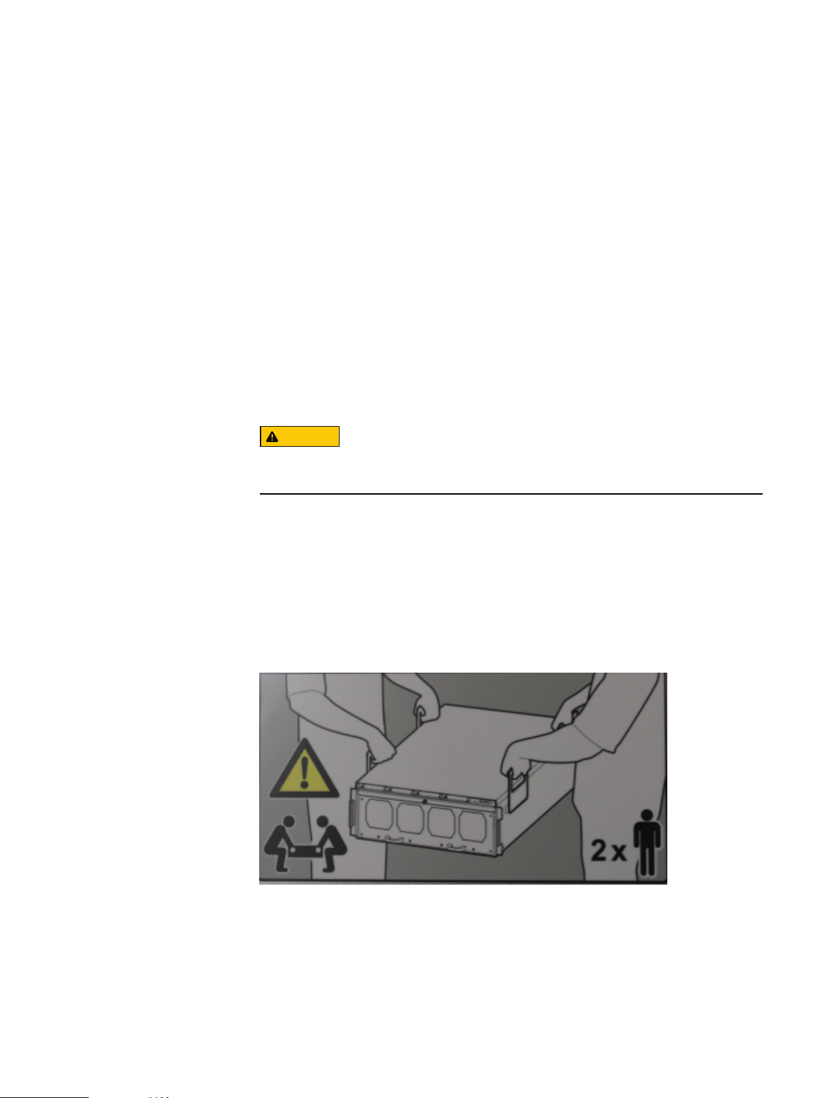
Do not lift system components by yourself. A DD9500/DD9800 system weighs up
to 117 lbs (53.2 kg), an ES30 expansion shelf weighs up to 68 lbs (30.8 kg), and a
DS60 shelf weighs up to 225 lbs (90.7 kg).
Data Domain systems are heavy. Use at least two people or a mechanical lift
to move any system.
l
Do not lift an expansion shelf by the handles on any modules. The handles are not
designed to support the weight of the populated shelf.
l
To comply with applicable safety, emission, and thermal requirements, covers
must not be removed and all bays must be fitted with plug-in modules.
l
Once removed from the shipping box, it is ok to lift the DD9500/DD9800 system
or the chassis with the four handles to place in a rack. You will need to remove the
handles from the sides before sliding the system in the rack. The four handles
should be saved for later use.
Figure 1
Warning about lifting the system
l
Load the rack with storage shelves beginning at the bottom and the DD9500
system in the designated location to prevent the rack from becoming top-heavy.
l
For ESD protection, Data Domain recommends that you wear a suitable antistatic
wrist or ankle strap. Observe all conventional ESD precautions when handling
plug-in modules and components.
Safety information 13

Planning and Site Preparation
l
Do not extend components on slide rails until you have loaded at least three or
more similarly weighted items in the rack, or unless the rack is bolted to the floor
or overhead structure to prevent tipping.
14 Data Domain DD9500 and DD9800 Systems 6.1 Hardware Overview and Installation Guide

CHAPTER 2
Hardware Overview
l
System features................................................................................................. 16
l
System specifications.........................................................................................16
l
DD9500/DD9800 front panel............................................................................. 18
l
Rear panel..........................................................................................................22
l
I/O module slot assignments.............................................................................. 27
l
Internal System Components.............................................................................30
l
Storage capacity................................................................................................33
Hardware Overview 15

Hardware Overview
System features
Table 2 DD9500/DD9800 system features
Feature DD9500 DD9800
Rack Height 4U, supported in four-post racks only 4U, supported in four-post racks only
Power 4 hot-swappable power units, 2 pairs of 1 +1
redundant
4 hot-swappable power units, 2 pairs of 1 +1
redundant
Fans 8 hot-swappable fans, redundant 8 hot-swappable fans, redundant
Internal drives 4 x 400 GB (base 10) hot-swappable solid state
drives (SSD)
SSD cache Optional 1 x 8 drive SSD shelf or 1 x 15 drive SSD
shelf
l
Systems with 256 GB of memory have 8 SSDs.
l
Systems with 512 GB of memory have 15 SSDs.
4 x 400 GB (base 10) hot-swappable solid state
drives (SSD)
1 x 8 drive SSD shelf or 1 x 15 drive SSD shelf
l
Systems with 256 GB of memory have 8
SSDs.
l
Systems with 768 GB of memory have 15
SSDs.
NVRAM One 8-GB NVRAM module for data integrity during
a power outage
I/O Module slots 11 I/O module (Fibre Channel, Ethernet, and SAS)
slots. Replaceable I/O modules are not hotswappable. See I/O module slot assignments on
page 27
Memory
l
Base: 256 GB
l
Expanded 512 GB
512 GB is required for DD Cloud Tier and Extended
Retention. HA is supported with both memory
configurations.
One 8-GB NVRAM module for data integrity
during a power outage
11 I/O module (Fibre Channel, Ethernet, and SAS)
slots. Replaceable I/O modules are not hotswappable. See I/O module slot assignments on
page 27
l
Base: 256 GB
l
Expanded 768 GB
768 GB is required for DD Cloud Tier and
Extended Retention. HA is supported with both
memory configurations.
Rack mounting Rack mount kit included with each system.
Adjustable between 24 - 36 in. (60.9–76.2 cm).
Rack mount kit included with each system.
Adjustable between 24 - 36 in. (60.9–76.2 cm).
Processors 4 Intel EX processors. 4 Intel EX processors.
Voltage 200–240 V~. Frequency: 50 Hz to 60 Hz. 200–240 V~. Frequency: 50 Hz to 60 Hz.
System specifications
Table 3
Model Watts BTU/hr Power (VA) Weight Width Depth Height
DD9500/
DD9800
16 Data Domain DD9500 and DD9800 Systems 6.1 Hardware Overview and Installation Guide
1887 6444 1981 117 lb / 53.2kg19 in / 48.3cm29.5 in / 74.9cm7 in / 17.8 cm
DD9500/DD9800 system specifications

Hardware Overview
l
Operating temperature: 50° to 95° F (10° to 35° C), derate 1.1° C per 1000 feet,
above 7500 feet up to 10,000 feet
l
Operating humidity: 20% to 80%, non-condensing
l
Non-operating temperature: -40° to +149° F (-40° to +65° C)
l
Operating acoustic noise: Sound power, LWAd, is 7.7 bels.
System specifications 17
Note
Hardware Overview
DD9500/DD9800 front panel
The four solid state drives (SSDs), the storage processor (SP), and the fans are
accessed from the front of the system. The SP must be pulled out to provide access
to the DIMMs. The fans are accessed without pulling or removing the SP and they are
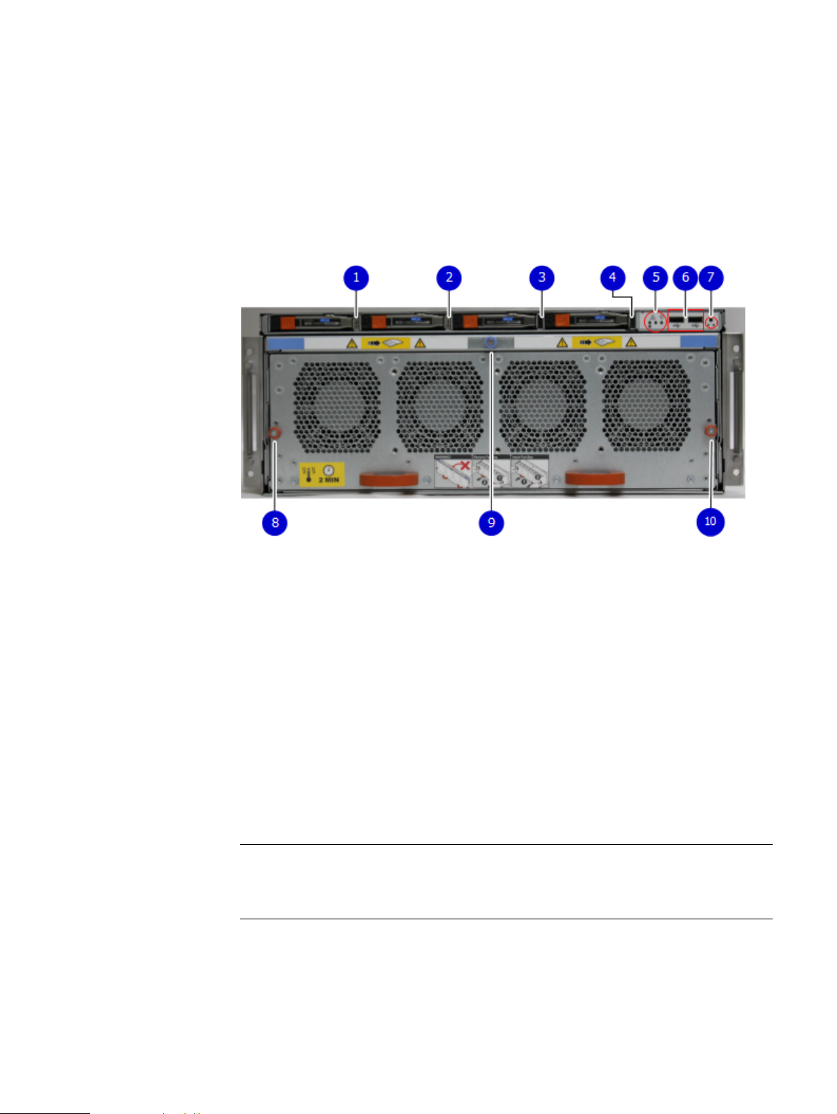
hot-swappable. The photo shows the interfaces on the front of the system.
Figure 2 Front panel components
Front LED indicators
On the front panel to the right of SSD #4 (in Slot 3) are 3 LEDs that show high level
system status. The System Power LED glows blue to show the system is powered on.
The system can have power (be plugged in) but the blue LEDs are off if the system is
powered off.
The SP Service LED is normally off, but glows amber whenever the storage processor
(SP) requires service. The Enclosure Service LED is normally off, but glows amber
whenever the SP or other replaceable parts require service. The System Power and
Enclosure Service LEDs are visible through the front bezel.
1. SSD slot 0
2. SSD slot 1
3. SSD slot 2
4. SSD slot 3
5. Front LEDs
6. USB ports
7. Power button
8. Fan tray thumbscrew (left)
9. SP module thumbscrew to secure the ejector handle
10. Fan tray thumbscrew (right)
18 Data Domain DD9500 and DD9800 Systems 6.1 Hardware Overview and Installation Guide
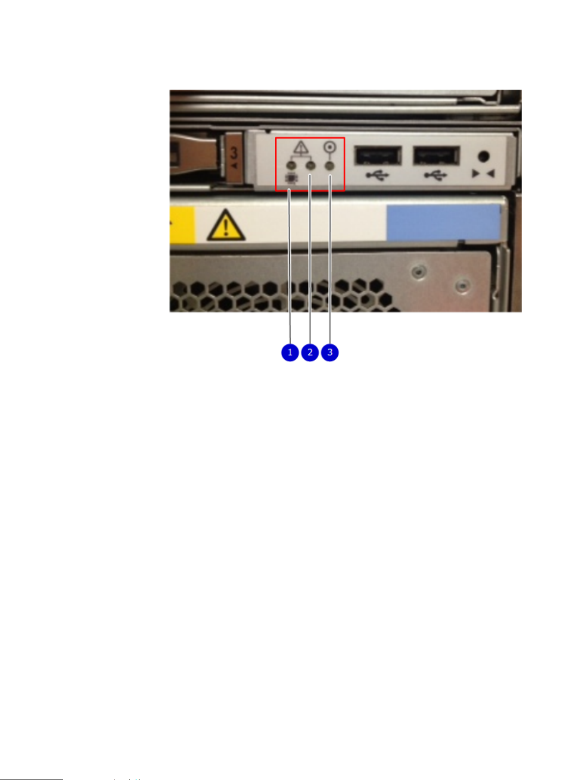
Figure 3 Service LEDs
Hardware Overview
1. SP service LED — Amber light indicates that the SP or one of its components
needs service.
2. Enclosure Service LED — This is normally off, but amber light indicates that the
enclosure or something within the enclosure— the fans, SP, I/O modules,
management module etc—requires service.
3. System power LED — Blue light indicates system running
Front LED indicators 19
Hardware Overview
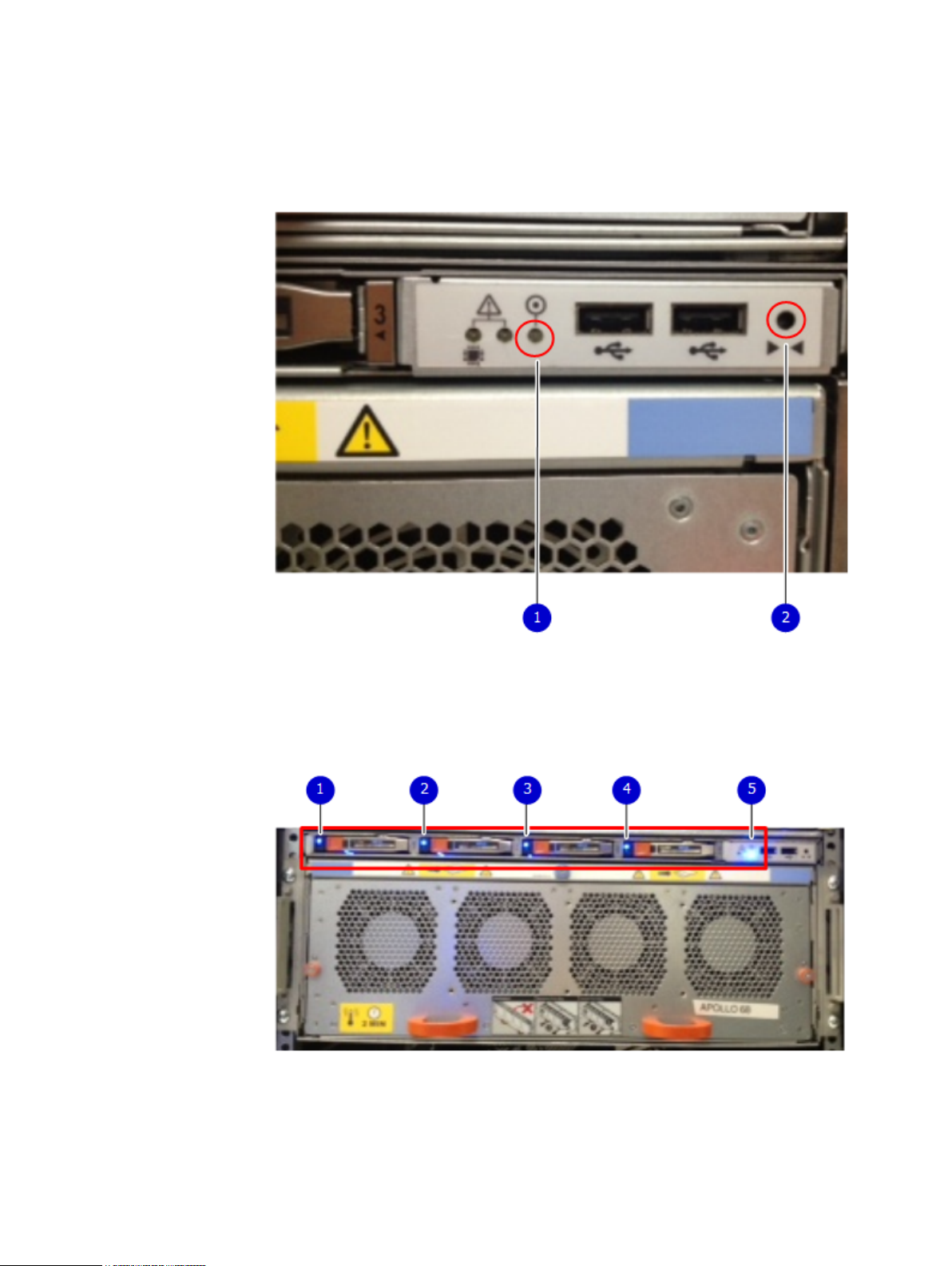
The power button shown in the picture is used when a system needs to be powered up
after a shut down using the system poweroff command. Once power is restored
the system power LED light turns blue.
Figure 4 Power button
1. System power LED — Blue light indicates system running
2. Power button
The LEDs in the front are shown in the following figure.
Figure 5
Front LEDs
1. SSD LED in slot 0
2. SSD LED in slot 1
3. SSD LED in slot 2
4. SSD LED in slot 3
5. System power LED — Blue light indicates system running
20 Data Domain DD9500 and DD9800 Systems 6.1 Hardware Overview and Installation Guide
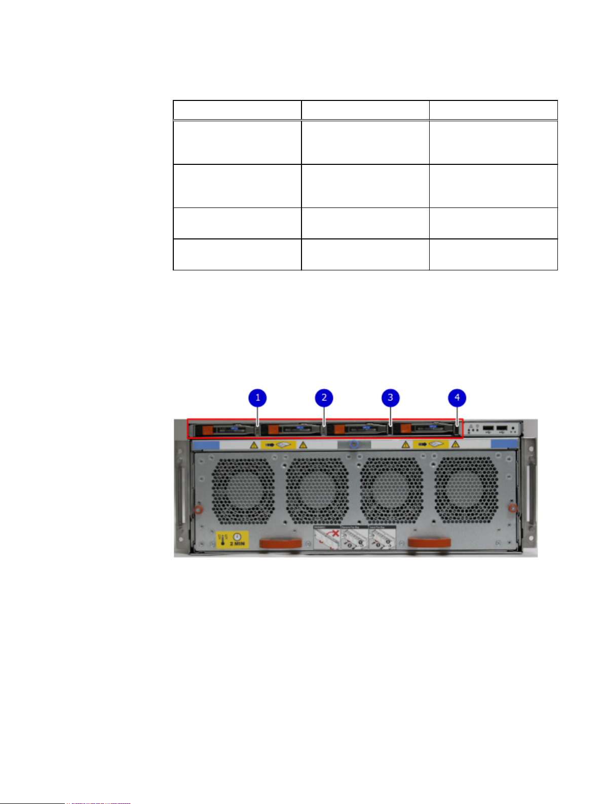
Table 4 Front panel LED status indicators
Part Description or Location State
Hardware Overview
System, SP fault Exclamation point within a
System, chassis fault Exclamation point within a
SSD Top LED Solid blue, disk ready, blinks
SSD Bottom LED Dark indicates healthy. Solid
Solid State Drives (SSD)
A system contains 4 hot-swappable 2.5 in. 400 GB SSD drives located in the front.
There are four drive bays numbered 0-3 from left to right. A dual drive failure allows
the DD9500/DD9800 system to operate without disruption.
Each drive has a blue colored power LED and an amber fault LED.
Figure 6
SSD drives
triangle
triangle
Dark indicates normal
operation. Amber indicates
failure.
Dark indicates normal
operation. Amber indicates a
fault condition.
while busy.
amber indicates disk fail.
1. Slot 0
2. Slot 1
3. Slot 2
4. Slot 3
Solid State Drives (SSD) 21
Hardware Overview
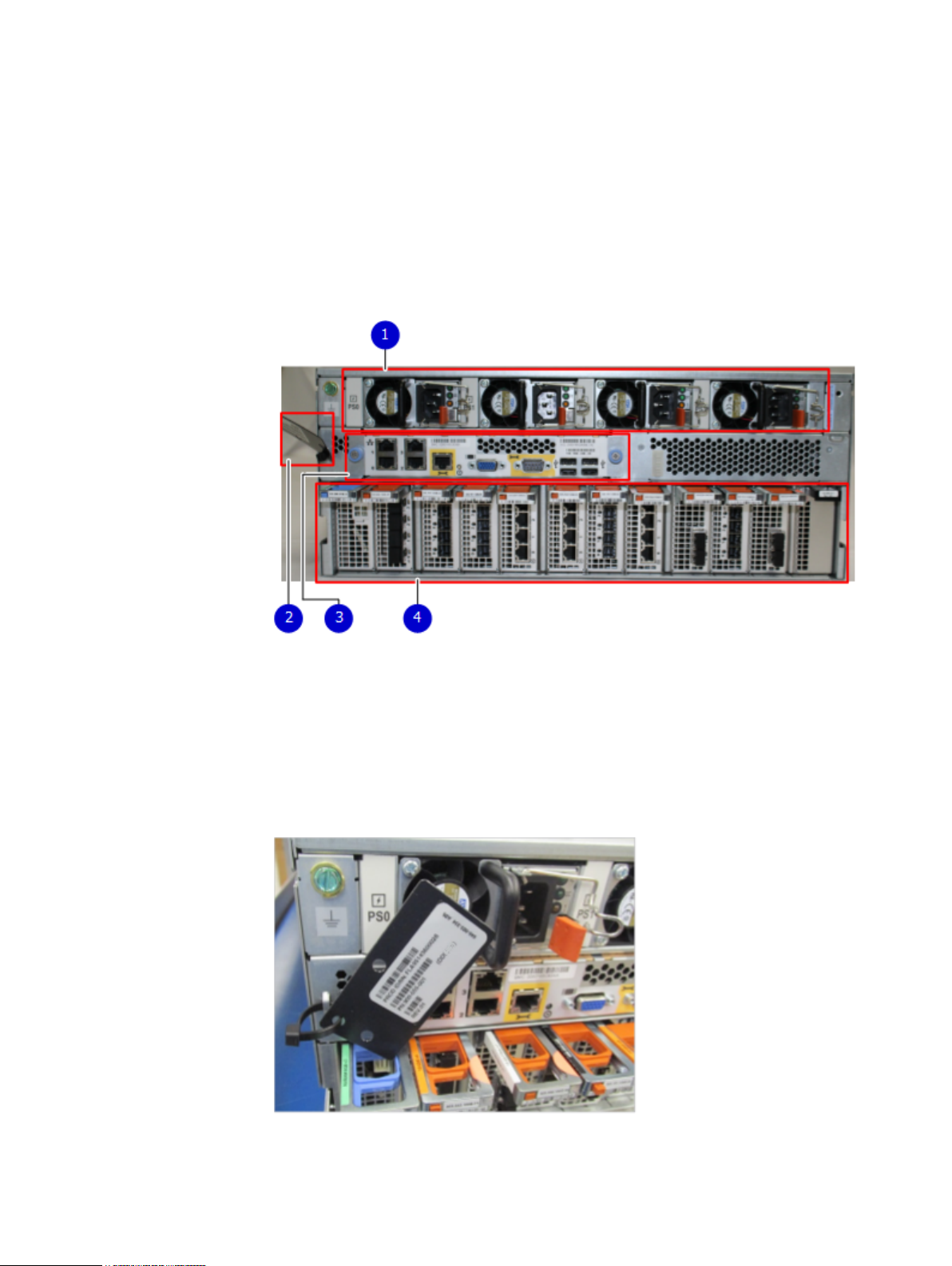
Rear panel
In the rear of the system, the top section contains the 4 power supply units. In the
middle of the section, on the left, is serial number tag location. To the right of the
serial number tag location is the management module. The lower section contains the
NVRAM and the I/O modules numbered 0 through 11 from left to right. The photo
shows the hardware features and interfaces on the rear of the system.
Figure 7 Features on rear of chassis
1. Power supply units
2. Serial number tag
3. Management module
4. NVRAM and IO modules (slots 0-11)
The figure shows the location of the serial number tag on the left of the management
module.
Figure 8
Serial number tag location
22 Data Domain DD9500 and DD9800 Systems 6.1 Hardware Overview and Installation Guide
Power supply units
Note
Hardware Overview
A DD9500/DD9800 system has four power supply units, numbered PSU0, PSU1,
PSU2, and PSU3 from left to right. Each power supply has its own integral cooling
fan.
The DD9500/DD9800 system should be powered from redundant AC sources. This
allows one AC source to fail or be serviced without impacting system operation. PSU0
and PSU1 should be attached to one AC source. PSU2 and PSU3 should be attached
to the other AC source.
The AC power plugs are located to the right of each power supply. The wire clips for
the AC cords hold the cords in place. The wire clips must be disengaged before
disconnecting the AC power to each power supply.
Figure 9 Four power supplies
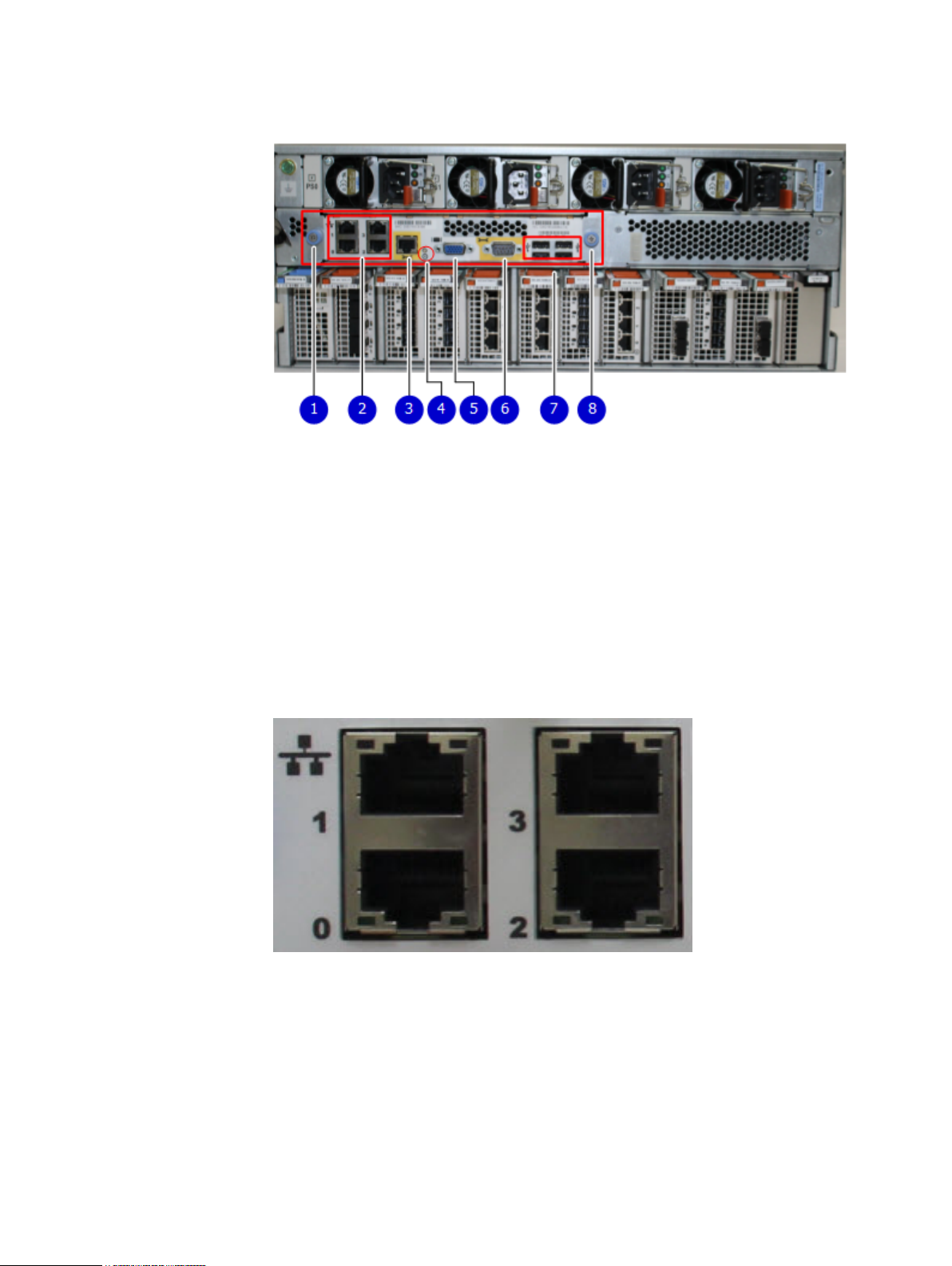
Management module
The following figure shows the location of the DD9500/DD9800 management module
on the rear of the system and identifies the interfaces.
Power supply units 23
Hardware Overview
Figure 10 Management module
1. Left blue thumbscrew to loosen the management module
2. 4 x 1000BaseT Ethernet ports (For details, see the picture - 1000BaseT Ethernet
ports)
3. Service network port (IPMI, 1000BaseT Ethernet port)
4. Service LED
5. VGA port
6. Serial port
7. Four USB ports
8. Right blue thumbscrew to loosen the management module
Rear LED Indicators
Figure 11
1000BaseT Ethernet ports
- Lower left port: physical #0, logical ethMa
- Top left port: physical #1, logical ethMb
- Lower right port: physical #2, logical ethMc
- Top right port: physical #3, logical ethMd
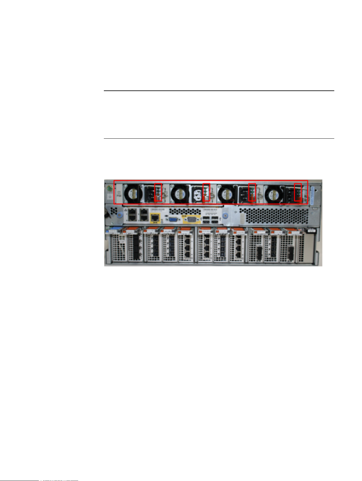
The rear elements containing LEDs include each power supply, each I/O module, and
the management module.
24 Data Domain DD9500 and DD9800 Systems 6.1 Hardware Overview and Installation Guide
The figure shows the rear LEDS.
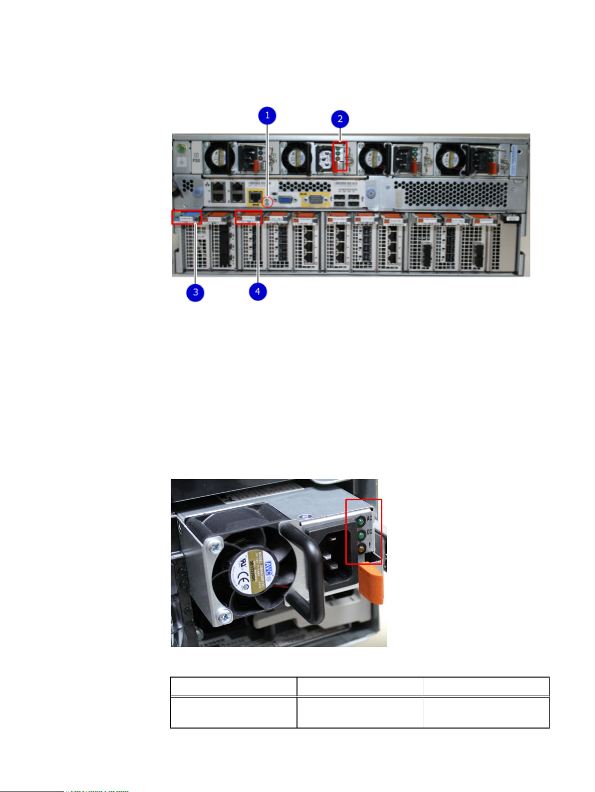
Figure 12 Rear LEDs
1. Management module service LEDs
2. Power supply LEDs
3. NVRAM LEDs
4. IO Module LEDS
Hardware Overview
The power supply LEDs include:
l
AC LED on top
l
DC LED in the middle
l
Service Required LED on the bottom
Figure 13
Table 5 Rear LED status indicators
Power supply LEDs
Part Description or Location State
Power supply AC LED Steady green indicates normal
AC input power.
Rear LED Indicators 25

Hardware Overview
Table 5 Rear LED status indicators (continued)
Part Description or Location State
Power supply DC LED Steady green indicates normal
DC output power.
Power supply Service LED Solid amber indicates a failed
power supply.
I/O module I/O module handle Solid green, I/O module
functioning normally; amber
indicates a fault condition.
Each IO module also has per
port LEDs. These are blue on
the FC, and SAS I/O modules.
They light when the port is
active.
Management module Bicolor LED Solid green, management
module functioning normally;
amber indicates the
management module requires
service.
Available I/O modules
I/O modules may include:
l
l
l
l
l
I/O module port physical mapping
I/O module ports are numbered starting with 0. When the I/O modules are inserted
vertically into the system chassis, port 0 is on the bottom.
I/O module port logical mapping
The numerical port labels on the I/O modules are identified logically in the DD OS
software by the following descriptions:
l
l
l
The following example is based on a four-port Ethernet I/O module installed in slot 1 of
the system chassis.
Quad port Ethernet 10GBase-SR Optical with LC connectors
Quad port Ethernet 10GBase-CX1 Direct Attach Copper with SPF+ module
Quad port Ethernet 10GBase-T Copper
Dual port 16 Gbps Fibre Channel
Quad port 6 Gbps SAS
I/O module type
I/O module slot
Alphabetic character corresponding to the physical port number
Table 6
Physical to logical port mapping example
Physical port Logical identifier
0 eth1a
26 Data Domain DD9500 and DD9800 Systems 6.1 Hardware Overview and Installation Guide
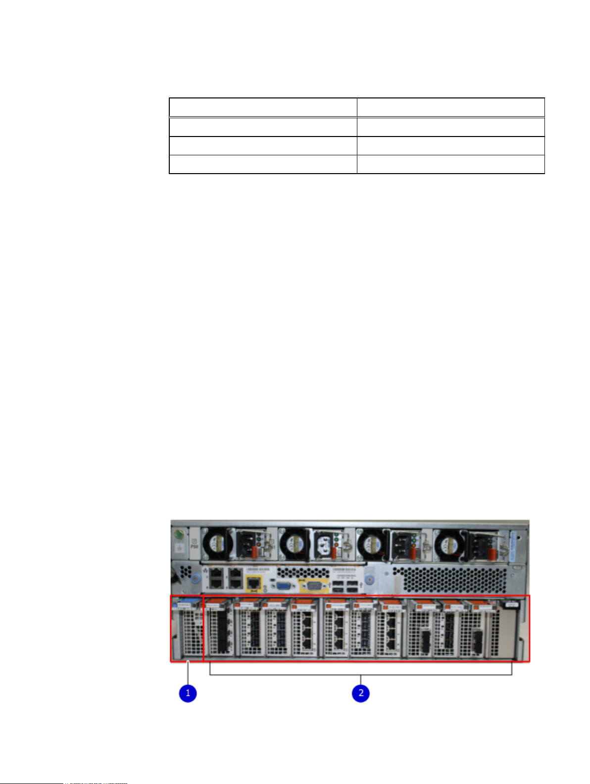
Table 6 Physical to logical port mapping example (continued)
Physical port Logical identifier
1 eth1b
2 eth1c
3 eth1d
Ethernet I/O modules
A system can have up to a maximum of four Ethernet I/O modules of any type. The
four Ethernet I/O module limit applies to any combination of the different types of
Ethernet I/O modules. In other words two 10GBaseT and two fiber optic Ethernet I/O
modules are allowed. But three of each is not allowed. The available Ethernet I/O
modules are listed in the Available I/O modules on page 26.
Fibre Channel (FC) I/O modules
An FC I/O module is a dual-port Fibre Channel module. Up to four FC I/O modules
may be installed. The optional virtual tape library (VTL) feature requires at least one
FC I/O module. Boost over Fibre Channel is an optional feature and requires at least
one FC I/O module. A maximum of four FC I/O modules may be installed in a system
using either VTL or the Boost protocol or a combination of both protocols.
Hardware Overview
SAS I/O modules
DD9500/DD9800 systems have three quad-port SAS I/O modules installed in slots 2,
3 and 6. DD9500/DD9800 systems configured with DD Extended Retention (ER) or
DD Cloud Tier software options require an additional SAS I/O module in slot 9.
I/O module slot assignments
The following figure shows the location of the NVRAM and I/O modules.
Figure 14
Location of NVRAM and I/O modules
1. NVRAM module—slot 0
Ethernet I/O modules 27

Note
Note
Hardware Overview
Figure 14 Location of NVRAM and I/O modules (continued)
2. I/O modules—slots 1 to 11 (See the I/O module slot assignments table.)
Slots 2, 3, and 6 (three I/O slots) are used for SAS I/O modules for systems without
Extended Retention (ER).
Slots 2, 3, 6, and 9 (four I/O slots) are for SAS I/O modules for systems with ER or
DD Cloud Tier software.
The table shows the I/O module slot assignments for the DD9500 and DD9800
systems. Each type of I/O module is restricted to certain slots.
The I/O module slot assignments for the DD9500 and DD9800 systems are the same.
Table 7 DD9500 and DD9800 I/O module slot assignments
Slot Base
configuratio
HA ER or DD Cloud
Tier
DD Cloud Tier
and HA
n
0 NVRAM NVRAM NVRAM NVRAM
1 Fibre Channel
(FC), Ethernet
or empty
2 SAS SAS SAS SAS
3 SAS SAS SAS SAS
4 FC, Ethernet or
empty
5 FC, Ethernet or
empty
6 SAS SAS SAS SAS
7 FC, Ethernet or
empty
8 FC, Ethernet or
empty
9 Not available
(contains a
filler)
Fibre Channel
(FC), Ethernet
or empty
FC, Ethernet or
empty
FC, Ethernet or
empty
FC, Ethernet or
empty
FC, Ethernet or
empty
Not available
(contains a
filler)
Fibre Channel (FC),
Ethernet or empty
FC, Ethernet or
empty
FC, Ethernet or
empty
FC, Ethernet or
empty
FC, Ethernet or
empty
SAS SAS
Fibre Channel (FC),
Ethernet or empty
FC, Ethernet or
empty
FC, Ethernet or
empty
FC, Ethernet or
empty
FC, Ethernet or
empty
10 FC, Ethernet or
empty
11 FC, Ethernet or
empty
28 Data Domain DD9500 and DD9800 Systems 6.1 Hardware Overview and Installation Guide
FC, Ethernet or
empty
10 Gb optical
Ethernet for
interconnect
between the
FC, Ethernet or
empty
FC, Ethernet or
empty
FC, Ethernet or
empty
10 Gb optical
Ethernet for
interconnect
between the
 Loading...