


Page 1

53-1002267-01
18 March 2011
PowerConnect B-FCX
Switch
Hardware Installation Guide
Page 2

Information in this document is subject to change without notice.
© 2011 Dell Inc. All rights reserved.
Reproduction of these materials in any manner whatsoever without the written permission of Dell Inc. is strictly forbidden.
Trademarks used in this text: Dell, the DELL logo,, Dell OpenManage , and PowerConnect are trademarks of Dell Inc.; Microsoft,
Windows, and Windows Server are either trademarks or registered trademarks of Microsoft Corporation in the United States and/
or other countries.
Other trademarks and trade names may be used in this document to refer to either the entities claiming the marks and names or
their products. Dell Inc. disclaims any proprietary interest in trademarks and trade names other than its own.
Regulatory Model Codes: FCX624-S, FCX648-S, FCX624-E, FCX624-I, FCX648-E, and FCX648-I
Page 3

Contents
About This Document
Audience . . . . . . . . . . . . . . . . . . . . . . . . . . . . . . . . . . . . . . . . . . . . . . . vii
Supported hardware and software . . . . . . . . . . . . . . . . . . . . . . . . . . vii
Document conventions. . . . . . . . . . . . . . . . . . . . . . . . . . . . . . . . . . . . vii
Text formatting . . . . . . . . . . . . . . . . . . . . . . . . . . . . . . . . . . . . . . . vii
Command syntax conventions . . . . . . . . . . . . . . . . . . . . . . . . . . viii
Notes, cautions, and danger notices . . . . . . . . . . . . . . . . . . . . .viii
Related publications . . . . . . . . . . . . . . . . . . . . . . . . . . . . . . . . . . . . . . viii
Getting technical help or reporting errors . . . . . . . . . . . . . . . . . . . . . . ix
Contacting Dell. . . . . . . . . . . . . . . . . . . . . . . . . . . . . . . . . . . . . . . .ix
Chapter 1 Product Overview
Hardware features . . . . . . . . . . . . . . . . . . . . . . . . . . . . . . . . . . . . . . . . 1
Control features . . . . . . . . . . . . . . . . . . . . . . . . . . . . . . . . . . . . . . . 3
Power supplies. . . . . . . . . . . . . . . . . . . . . . . . . . . . . . . . . . . . . . .13
Chapter 2 Installing the PowerConnect B-FCX Switch
Unpacking the device . . . . . . . . . . . . . . . . . . . . . . . . . . . . . . . . . . . . .15
Package contents . . . . . . . . . . . . . . . . . . . . . . . . . . . . . . . . . . . . 15
General requirements . . . . . . . . . . . . . . . . . . . . . . . . . . . . . . . . .15
Installation tasks. . . . . . . . . . . . . . . . . . . . . . . . . . . . . . . . . . . . . . . . .16
Installation precautions . . . . . . . . . . . . . . . . . . . . . . . . . . . . . . . . . . . 16
General precautions . . . . . . . . . . . . . . . . . . . . . . . . . . . . . . . . . . 17
Lifting precautions . . . . . . . . . . . . . . . . . . . . . . . . . . . . . . . . . . . . 17
Power precautions . . . . . . . . . . . . . . . . . . . . . . . . . . . . . . . . . . . . 17
Preparing the installation site . . . . . . . . . . . . . . . . . . . . . . . . . . . . . .18
Cabling infrastructure . . . . . . . . . . . . . . . . . . . . . . . . . . . . . . . . .18
Installation location . . . . . . . . . . . . . . . . . . . . . . . . . . . . . . . . . . . 18
Installing the device. . . . . . . . . . . . . . . . . . . . . . . . . . . . . . . . . . . 19
Desktop installation. . . . . . . . . . . . . . . . . . . . . . . . . . . . . . . . . . .19
Rack mount installation . . . . . . . . . . . . . . . . . . . . . . . . . . . . . . .20
Connecting devices in a stack. . . . . . . . . . . . . . . . . . . . . . . . . . .21
Powering on the system . . . . . . . . . . . . . . . . . . . . . . . . . . . . . . . . . . . 24
Attaching a PC or terminal . . . . . . . . . . . . . . . . . . . . . . . . . . . . . . . . . 25
Wiring map for serial cable . . . . . . . . . . . . . . . . . . . . . . . . . . . . .26
Installing and replacing a power supply unit. . . . . . . . . . . . . . . . . . .26
Installing or replacing fan trays on PowerConnect B-FCX624s and
PowerConnect B-FCX648s devices . . . . . . . . . . . . . . . . . . . . . . . . . . 28
PowerConnect B-FCX Switch Hardware Installation Guide iii
53-1002267-01
Page 4

Installing or replacing fan trays on PowerConnect B-FCX624 and
PowerConnect B-FCX648 devices . . . . . . . . . . . . . . . . . . . . . . . . . . .28
Installing an optional module on PowerConnect B-FCX624s or
PowerConnect B-FCX648s devices . . . . . . . . . . . . . . . . . . . . . . . . . . 30
Installing an optional module in PowerConnect B-FCX624 and
PowerConnect B-FCX648 devices . . . . . . . . . . . . . . . . . . . . . . . . . . . 31
Chapter 3 Checking Network Devices and Testing Connectivity
Assigning permanent passwords . . . . . . . . . . . . . . . . . . . . . . . . . . . .33
Setting passwords . . . . . . . . . . . . . . . . . . . . . . . . . . . . . . . . . . . .34
Recovering from a lost password . . . . . . . . . . . . . . . . . . . . . . . . 34
Configuring IP addresses . . . . . . . . . . . . . . . . . . . . . . . . . . . . . . . . . .35
Devices running Layer 2 software . . . . . . . . . . . . . . . . . . . . . . .35
Devices running Layer 3 software . . . . . . . . . . . . . . . . . . . . . . .36
Connecting network devices . . . . . . . . . . . . . . . . . . . . . . . . . . . .39
Connectors. . . . . . . . . . . . . . . . . . . . . . . . . . . . . . . . . . . . . . . . . .39
Cable specifications. . . . . . . . . . . . . . . . . . . . . . . . . . . . . . . . . . .39
Connecting to Ethernet or fast Ethernet hubs . . . . . . . . . . . . . .39
Connecting to workstations, servers, or routers . . . . . . . . . . . .40
Connecting a network device to a fiber port . . . . . . . . . . . . . . .40
Testing connectivity. . . . . . . . . . . . . . . . . . . . . . . . . . . . . . . . . . . . . . .43
Pinging an IP address . . . . . . . . . . . . . . . . . . . . . . . . . . . . . . . . . 43
Observing LEDs . . . . . . . . . . . . . . . . . . . . . . . . . . . . . . . . . . . . . . 43
Tracing a route . . . . . . . . . . . . . . . . . . . . . . . . . . . . . . . . . . . . . . .45
Troubleshooting network connections. . . . . . . . . . . . . . . . . . . . . . . . 45
Using Virtual Cable Testing to diagnose a cable . . . . . . . . . . . .46
Digital optical monitoring . . . . . . . . . . . . . . . . . . . . . . . . . . . . . . 47
Chapter 4 Managing the PowerConnect B-FCX Hardware
Managing temperature settings. . . . . . . . . . . . . . . . . . . . . . . . . . . . .49
Using the temperature sensor . . . . . . . . . . . . . . . . . . . . . . . . . . 49
Removing MAC address entries . . . . . . . . . . . . . . . . . . . . . . . . . 53
Displaying PowerConnect B-FCX CPU usage . . . . . . . . . . . . . . . . . . .53
Hardware maintenance schedule . . . . . . . . . . . . . . . . . . . . . . . . . . .54
Replacing a copper or fiber optic module . . . . . . . . . . . . . . . . . . . . .54
Removing a copper or fiber optic module . . . . . . . . . . . . . . . . .54
Cabling a fiber optic module . . . . . . . . . . . . . . . . . . . . . . . . . . . .55
Cleaning the fiber optic connectors . . . . . . . . . . . . . . . . . . . . . . 55
iv PowerConnect B-FCX Switch Hardware Installation Guide
53-1002267-01
Page 5

Chapter 5 Hardware Specifications
Hardware specifications . . . . . . . . . . . . . . . . . . . . . . . . . . . . . . . . . . .57
Physical dimensions and weight. . . . . . . . . . . . . . . . . . . . . . . . . 57
Environmental considerations . . . . . . . . . . . . . . . . . . . . . . . . . . 57
Cooling system and fans . . . . . . . . . . . . . . . . . . . . . . . . . . . . . . . 58
Pinouts and signalling . . . . . . . . . . . . . . . . . . . . . . . . . . . . . . . . .61
Cable specifications. . . . . . . . . . . . . . . . . . . . . . . . . . . . . . . . . . .62
Power cords . . . . . . . . . . . . . . . . . . . . . . . . . . . . . . . . . . . . . . . . .63
AC power supply specifications. . . . . . . . . . . . . . . . . . . . . . . . . . 63
Chapter 6 Troubleshooting
Diagnosing switch indicators . . . . . . . . . . . . . . . . . . . . . . . . . . . . . . .65
Power and cooling problems. . . . . . . . . . . . . . . . . . . . . . . . . . . .65
Installation . . . . . . . . . . . . . . . . . . . . . . . . . . . . . . . . . . . . . . . . . .65
In-band access . . . . . . . . . . . . . . . . . . . . . . . . . . . . . . . . . . . . . . .66
Appendix A Regulatory Statements
USA (FCC CFR 47 Part 15 Warning) . . . . . . . . . . . . . . . . . . . . . . . . . . 67
Industry Canada statement . . . . . . . . . . . . . . . . . . . . . . . . . . . . . . . .67
Europe and Australia (CISPR 22 Class A Warning) . . . . . . . . . . . . . .67
Japan (VCCI). . . . . . . . . . . . . . . . . . . . . . . . . . . . . . . . . . . . . . . . . . . . . 67
Japan power cord . . . . . . . . . . . . . . . . . . . . . . . . . . . . . . . . . . . . . . . .68
Korea . . . . . . . . . . . . . . . . . . . . . . . . . . . . . . . . . . . . . . . . . . . . . . . . . .68
Russia . . . . . . . . . . . . . . . . . . . . . . . . . . . . . . . . . . . . . . . . . . . . . . . . .68
Regulatory compliance . . . . . . . . . . . . . . . . . . . . . . . . . . . . . . . . . . . .69
Appendix B Cautions and Danger Notices
Cautions. . . . . . . . . . . . . . . . . . . . . . . . . . . . . . . . . . . . . . . . . . . . . . . . 71
Danger notices . . . . . . . . . . . . . . . . . . . . . . . . . . . . . . . . . . . . . . . . . .73
PowerConnect B-FCX Switch Hardware Installation Guide v
53-1002267-01
Page 6

vi PowerConnect B-FCX Switch Hardware Installation Guide
53-1002267-01
Page 7

About This Document
Audience
This document is designed for system administrators with a working knowledge of Layer 2 and
Layer 3 switching and routing.
If you are using a Dell Layer 3 Switch, you should be familiar with the following protocols if
applicable to your network – IP, RIP, OSPF, BGP, ISIS, IGMP, PIM, DVMRP, and VRRP.
Supported hardware and software
The following hardware platform is supported in this release:
• PowerConnect B-FCX624s
• PowerConnect B-FCX648s
• PowerConnect B-FCX624
• PowerConnect B-FCX648
Document conventions
This section describes text formatting conventions and important notice formats used in this
document.
Text formatting
The following narrative-text formatting conventions are used in this guide.
bold text Identifies command names
italic text Provides emphasis
code text Identifies CLI output
Identifies the names of user-manipulated GUI elements
Identifies keywords
Identifies text to enter at the GUI or CLI
Identifies variables
Identifies document titles
PowerConnect B-FCX Switch Hardware Installation Guide vii
53-1002267-01
Page 8
For readability, command names in the narrative portions of this guide are presented in bold: for
NOTE
CAUTION
DANGER
example, show version. In actual examples, command lettercase is often all lowercase. Otherwise,
this manual specifically notes those cases in which a command is case sensitive.
.
Command syntax conventions
The following conventions apply to the command syntax in this guide.
command and
parameters
[ ] Optional parameter.
variable Variables are printed in italics enclosed in angled brackets < >.
... Repeat the previous element, for example “member[;member...]”
| Choose from one of the parameters.
Commands and parameters are printed in bold.
Notes, cautions, and danger notices
The following note, cautions, and danger statements are used in this manual. They are listed here
in order of increasing severity of potential hazards.
A note provides a tip, guidance or advice, emphasizes important information, or provides a reference
to related information.
A Caution statement alerts you to situations that can be potentially hazardous to you or cause
damage to hardware, firmware, software, or data.
A Danger statement indicates conditions or situations that can be potentially lethal or extremely
hazardous to you. Safety labels are also attached directly to products to warn of these conditions
or situations.
Related publications
The following Dell documents supplement the information in this guide:
• PowerConnect B-FCX Series Configuration Guide - Provides configuration procedures, including
configuration information for enterprise routing protocols.
• PowerConnect B-MLXe MIB Reference – Contains the Simple Network Management Protocol
(SNMP) Management Information Base (MIB) objects supported on de devices.
viii PowerConnect B-FCX Switch Hardware Installation Guide
53-1002267-01
Page 9

NOTE
For the latest edition of these documents, which contain the most up-to-date information, refer to
NOTE
Product Manuals at support.dell.com.
Getting technical help or reporting errors
Dell is committed to ensuring that your investment in our products remains cost-effective. If you
need assistance, or find errors in the manuals, contact Dell Technical Support.
Contacting Dell
For customers in the United States, call 800-WWW.DELL (800.999.3355).
If you do not have an active Internet connection, you can find contact information on your purchase
invoice, packing slip, bill, or Dell product catalog.
Dell provides several online and telephone-based support and service options. Availability varies by
country and product, and some services may not be available in your area. To contact Dell for sales,
technical support, or customer service issues:
1. Visit http://support.dell.com.
2. Click your country or region at the bottom of the page. For a full listing of countries and regions,
click All.
3. In the Support menu, click All Support.
Choose the method of contacting Dell that is convenient for you.
PowerConnect B-FCX Switch Hardware Installation Guide ix
53-1002267-01
Page 10

x PowerConnect B-FCX Switch Hardware Installation Guide
53-1002267-01
Page 11

Chapter
Product Overview
Hardware features
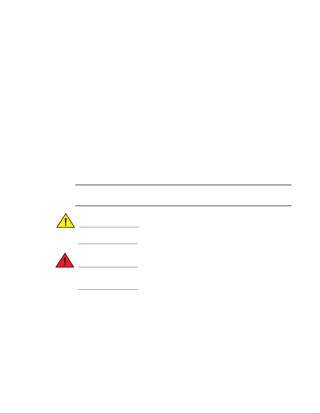
The following hardware platforms are supported by this release of this guide:
• The PowerConnect B-FCX624s stackable switch has twenty 10/100/1000 Mbps RJ45 ports
plus four Combo ports, which include four 10/100/1000 Mbps RJ45 ports and four 100/1000
Mbps SFP ports. The switch has two management interfaces, a DB9 serial port (Console) on
the front panel and an RJ45 port (Out-of-band Management Interface) on the rear panel. Two
rear-panel power supply receptacles allow for up to two power supply units. Two dedicated 16
GbE CX4 ports on the rear panel allow stacking for up to eight units. The front panel also has a
module slot for an optional two-port 10 Gbps XFP module.
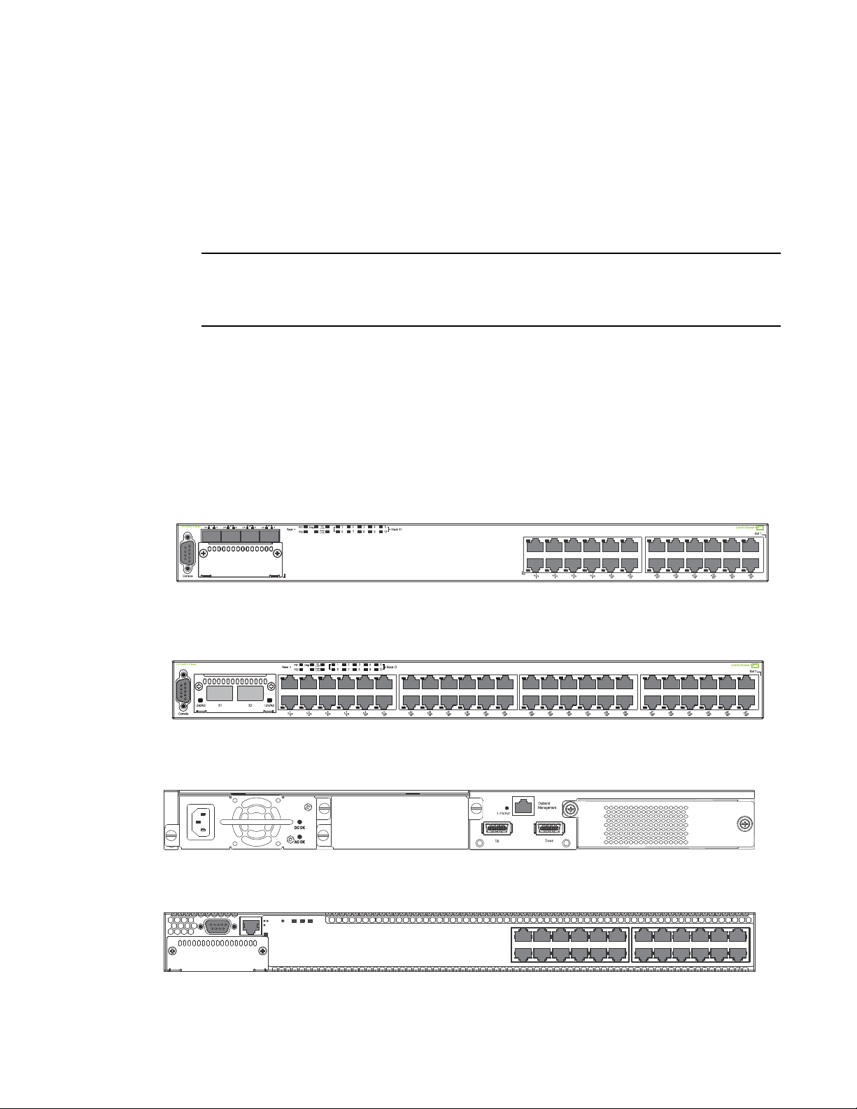
• The PowerConnect B-FCX648s stackable switch has forty four 10/100/1000 Mbps RJ45 ports
plus four Combo ports, which include four 10/100/1000 Mbps RJ45 ports and four 100/1000
Mbps SFP ports. The switch has two management interfaces, a DB9 serial port (Console) on
the front panel and an RJ45 port (Out-of-band Management Interface) on the rear panel. Two
rear-panel power supply receptacles allow for up to two power supply units. Two dedicated 16
Gbps Ethernet CX4 ports on the rear panel allow stacking for up to eight units. The front panel
also has a module slot for an optional two-port 10 Gbps Ethernet XFP module.
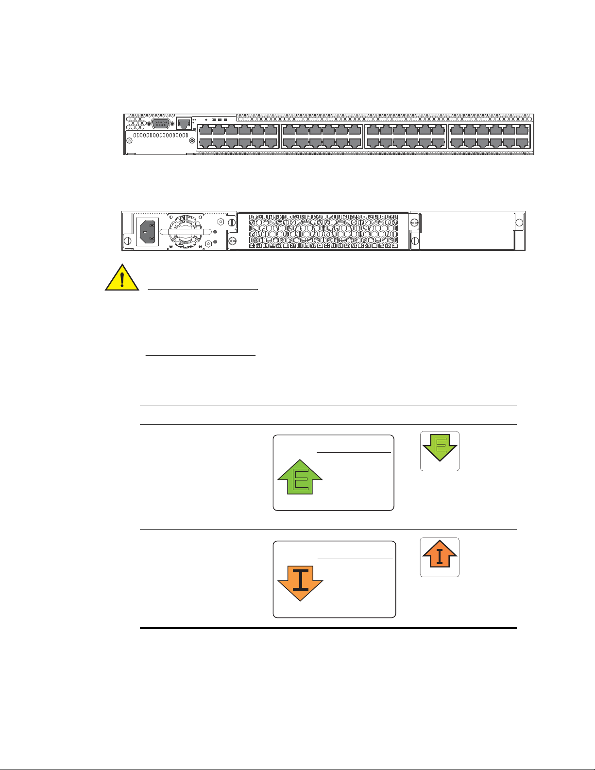
• The PowerConnect B-FCX624-E switch has twenty four 10/100/1000 Mbps RJ45 ports plus
four Combo 1 Gbps ports. The device has two management interfaces on the front panel, a
DB9 serial port (Console) and an RJ45 port (Out-of-band Management Interface). The front
panel has a slot for an optional four-port 1GbE SFP module (works as Combo port) or four-port
10 Gbps SFP+ module. On the rear panel a removable fan tray provides a cooling airflow from
the front to the back (FtB) of the device. Two rear-panel power supply receptacles
accommodate up to two power supply units that also support a front-to-back cooling airflow.
• The PowerConnect B-FCX624-I switch has twenty four 10/100/1000 Mbps RJ45 ports plus
four Combo 1 Gbps ports. The device has two management interfaces on the front panel, a
serial port (Console) and an RJ45 port (Out-of-band Management Interface). The front panel
has a slot for an optional four-port 1GbE SFP module (works as Combo port) or four-port 10
Gbps SFP+ module. On the rear panel a removable fan tray provides a cooling airflow from the
back to the front (BtF) of the device. Two rear-panel power supply receptacles accommodate up
to two power supply units that also support a back-to-front cooling airflow.
• The PowerConnect B-FCX648-E switch has forty four 10/100/1000 Mbps RJ45 ports plus four
Combo 1 Gbps ports. The device has two management interfaces on the front panel, a serial
port (Console) and an RJ45 port (Out-of-band Management Interface). The front panel has a
slot for an optional four-port 1GbE SFP module (works as Combo port) or four-port 10 Gbps
SFP+ module. On the rear panel a removable fan tray provides a cooling airflow from the front
to the back (FtB) of the device. Two rear-panel power supply receptacles accommodate up to
two power supply units that also support a front-to-back cooling airflow.
1
PowerConnect B-FCX Switch Hardware Installation Guide 1
53-1002267-01
Page 12
Hardware features
NOTE
Slot 3
A/S
A/S
1357911 131517192123
2 4 6 8 10 12 14 16 18 20 22 24
Reset
1PS2Diag
Console
Mgmt
1
• The PowerConnect B-FCX648-I switch has forty four 10/100/1000 Mbps RJ45 ports plus four
Combo 1 Gbps ports. The device has two management interfaces on the front panel, a serial
port (Console) and an RJ45 port (Out-of-band Management Interface). The front panel has a
slot for an optional four-port 1GbE SFP module, (works as Combo port) or four-port 10 Gbps
SFP+ module. On the rear panel a removable fan tray provides a cooling airflow from the back
to the front (BtF) of the device. Two rear-panel power supply receptacles accommodate up to
two power supply units that also support a back-to-front cooling airflow.
All PowerConnect B-FCX models support Layer 2 and Enterprise Layer 3 protocols (RIP, OSPF, PIM).
PowerConnect B-FCX models can be ordered from the factory as -ADV (Advanded Layer 3) models,
which adds support for the Layer 3 BGP routing protocol.
The following sections describe the physical characteristics of the PowerConnect B-FCX models. For
more details about physical dimensions, power supply specifications, and pinouts, refer to
“Hardware Specifications” on page 57.
The following figures show the front panels of the PowerConnect B-FCX models. For more
information about Combo ports, see “Combination ports” on page 4. For more information about
control features in general, see “Control features” on page 3.
FIGURE 1 PowerConnect B-FCX624s front panel
FIGURE 2 PowerConnect B-FCX648s front panel
FIGURE 3 PowerConnect B-FCX624s and PowerConnect B-FCX648s rear panel
FIGURE 4 PowerConnect B-FCX624-E and PowerConnect B-FCX624-I front panel
2 PowerConnect B-FCX Switch Hardware Installation Guide
53-1002267-01
Page 13
Hardware features
CAUTION
25 27 29 31 33 35 37 39 41 43 45 47
26 28 30 32 34 36 38 40 42
44
46 48
1357911 131517192123
2 4 6 8 10 12 14 16 18 20 22 24
Reset
1PS2 Diag
Console
Mgmt
AIRFLOW
WARNING
POWER SUPPLY/FAN
FRU TYPES MUST
BE THE SAME
E
AIRFLOW
WARNING
POWER SUPPLY/FAN
FRU TYPES MUST
BE THE SAME
AIRFLOW
1
FIGURE 5 PowerConnect B-FCX648-E and PowerConnect B-FCX648-I front panel
FIGURE 6 PowerConnect B-FCX624-E, PowerConnect B-FCX624-I, PowerConnect B-FCX648-E ,
PowerConnect B-FCX648-I rear panels
For the PowerConnect B-FCX624-E, PowerConnect B-FCX624-I, PowerConnect B-FCX648-E , and
PowerConnect B-FCX648-I devices, be sure that the airflow direction of the power supply unit
matches that of the installed resiliant quad-fan fan tray. The power supplies and fan trays are
clearly labeled with either a green arrow with an “E”, or an orange arrow with an “I” as shown in
Tab le 1.
TABLE 1 Power supply and fan tray labels for PowerConnect B-FCX624-E, PowerConnect
B-FCX624-I, PowerConnect B-FCX648-E, and PowerConnect B-FCX648-I devices
Device Label on required power supply Label on required fan tray
PowerConnect B-FCX624-E and
PowerConnect B-FCX648-E
E
AIRFLOW
PowerConnect B-FCX624-I and
PowerConnect B-FCX648-I
Control features
Each device front panel includes the following control features:
• Serial management interface (the DB9 port labeled Console)
PowerConnect B-FCX Switch Hardware Installation Guide 3
53-1002267-01
Page 14

Hardware features
1
• Out-of-band RJ45 management Interface
Serial management interface (DB9 Console port)
The serial management interface allows you to configure and manage the device using a
third-party terminal emulation application on a directly-connected PC. A straight-through EIA or TIA
DB9 serial cable (M or F) ships with the device. The serial management interface (the DB9 Console
port) is located in the left corner of the front panel.
Out-of-band RJ45 management interface
The out-of-band RJ45 management interface enables you to configure and manage the device
using a third-party terminal emulation application on a directly-connected PC.
Network interfaces for PowerConnect B-FCX624s and PowerConnect B-FCX648s
PowerConnect B-FCX devices contain the following interfaces:
• 10/100/1000 Mbps ports with RJ45 copper connectors
• 100/1000 Mbps ports with mini-GBIC slots for SFP MSA-compliant fiber transceivers
• Optional 2-port 10Gbps Ethernet XFP module
• CX4 stacking ports
Network interfaces for PowerConnect B-FCX624 and PowerConnect B-FCX648
PowerConnect B-FCX devices contain the following interfaces:
• 10/100/1000 ports with RJ45 copper connectors
• 100/1000 ports with mini-GBIC slots for MSA-compliant SFP transceivers
• Optional 4-port 1Gbps Ethernet SFP module
• Optional 4-port 10Gbps Ethernet SFP+ module
PowerConnect B-FCX 10/100/1000 BASE-T ports
All PowerConnect B-FCX devices except for the fiber models contain 24 or 48 RJ45 ports that
operate at 10 Mbps or 100 Mbps, half or full duplex, or at 1000 Mbps, full duplex. Because all
ports support automatic MDI or MDI-X operation, you can use straight-through cables for all
network connections to PCs or servers, or to other switches or hubs. In addition, it is ideal and
preferred to use straight-through cable for switch-to-switch connections.
Each of these ports supports auto-negotiation, so the optimum transmission mode (half or full
duplex), and the data rate (10, 100, or 1000 Mbps) can be selected automatically. If a device
connected to one of these ports does not support auto-negotiation, the communication mode of
the port can be configured manually.
Combination ports
PowerConnect B-FCX devices contain four combination ports, which are four Small Form Factor
Pluggable (SFP) network interfaces (1F~4F) that are shared with four of the RJ45 ports (ports 1~4).
In the default configuration, if an SFP transceiver is installed in a slot and has a valid link on its
port, the associated RJ45 port is disabled and cannot be used. The switch can also be configured
to force the use of a combination RJ45 port or SFP slot, as required.
4 PowerConnect B-FCX Switch Hardware Installation Guide
53-1002267-01
Page 15

Hardware features
NOTE
1
PowerConnect B-FCX624 and PowerConnect B-FCX648 devices do not ship with SFP ports. You must
install the optional SFP or SFP+ module for SFP support.
Slot designations
Tabl e 2 lists the slot designations for PowerConnect B-FCX models.
TABLE 2 Stack unit slots for PowerConnect B-FCX stackable devices
Device Slot 1 Slot 2 Slot 3
PowerConnect
B-FCX624s
PowerConnect
B-FCX648s
PowerConnect
B-FCX624
devices with
optional four-port
1 Gbps SFP
module
PowerConnect
B-FCX648
devices with
optional four-port
1 Gbps SFP
module
PowerConnect
B-FCX624
devices with
optional four-port
10 Gbps SFP+
module
PowerConnect
B-FCX648
devices with
optional four-port
10 Gbps SFP+
module
20 10/100/1000 Mbps ports plus 4 Combo
ports (RJ45 ports 1-4, or SFP ports 1F-4F)
44 20 10/100/1000 Mbps ports plus 4
Combo ports (RJ45 ports 1-4, or SFP ports
1F-4F)
20 10/100/1000 Mbps RJ45 ports, plus
4-port 1 Gbps SFP module (optional)
combined with the first four 10/100/1000
Mbps RJ45 copper ports (acting as a
Combo port).
40 10/100/1000 Mbps RJ45 ports, plus
4-port 1 Gbps SFP module (optional)
combined with the first four 10/100/1000
Mbps RJ45 copper ports (acting as a
Combo port).
24 10/100/1000 Mbps RJ45 ports 4-port 10 Gbps SFP+
44 10/100/1000 Mbps ports on front
panel
Two 16 Gbps uplink ports
on rear panel, or two Gbps
XFP ports (optional
module on front panel)
Two 16 Gbps ports on rear
panel, or two Gbps XFP
ports (optional module on
front panel)
N/A Optional four-port
N/A Optional four-port
module (optional) on front
panel
4-port 10 Gbps SFP+
module (optional) on front
panel
Two G b p s
XFP ports (optional
module on front
panel)
Two G b p s
XFP ports (optional
module on front
panel)
1 Gbps SFP
module
1 Gbps SFP
module
N/A
N/A
PowerConnect B-FCX Switch Hardware Installation Guide 5
53-1002267-01
Page 16

Hardware features
1
SFP interfaces
Tab le 3 describes the network interfaces supported on PowerConnect B-FCX devices.
TABLE 3 SFP network interfaces
Interface Show Media Description Description
1000Base-BX-D M-GBXD 1000Base-BXD SFP optic
SMF, transmits at 1490nm
and receives at 1310nm,
LC connector, single strand
SMF fiber. This optic
should only be connected
to an E1MG-BXU at the far
end.
1000Base-BX-U M-GBXU 1000Base-BX-U SFP optic
SMF, transmits at 1310nm
and receives at 1490nm,
LC connector, single strand
SMF fiber. This optic
should only be connected
to an E1MG-BXD at the far
end.
1000Base-LHA M-LHA 1000Base-LHA SFP optic,
SMF, LC connector, Optical
Monitoring Capable
1000Base-LX M-LX 1000Base-LX SFP optic,
SMF, LC connector, Optical
Monitoring Capable
1000Base-SX M-SX 1000Base-SX SFP optic,
MMF, LC connector, Optical
Monitoring Capable
100Base-FX M-FX 100Base-FX SFP optic
MMF 8 Pack, LC connector,
Optical Monitoring Capable
100Base-FX-IR M-FX_IR 100Base-FX-IR SFP optic
for SMF with LC connector,
Optical Monitoring
Capable. For distances up
to 15Km.
100Base-FX-LR M-FX-LR 100Base-FX-LRSFP optic
for SMF with LC connector,
Optical Monitoring
Capable. For distances up
to 40Km.
Optional two-port 10 Gbps XFP uplink module
The PowerConnect B-FCX624s and PowerConnect B-FCX648s devices include a slot on the front
panel for a two-port 10 Gbps XFP uplink module. This module operates at 10 Gbps full duplex
mode.
6 PowerConnect B-FCX Switch Hardware Installation Guide
53-1002267-01
Page 17
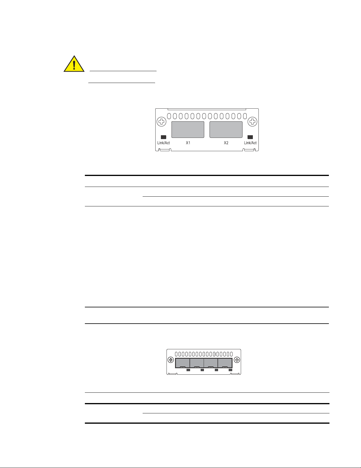
CAUTION
The optional 10Gbps XFP module is not hot-swappable.
NOTE
FCX-4G
1F 2F 3F 4F
FIGURE 7 Two-port 10 Gbps XFP module
TABLE 4 10 Gbps XFP module port status LEDs
LED Condition Status
Hardware features
1
Link or Act LED (Link or
Activity)
On or flashing Green Port has a valid link at 10 Gbps. Flashing indicates activity.
Off The link is down.
Optional Four-port 1 Gbps SFP and 10 Gbps SFP+ modules
The PowerConnect B-FCX624 and PowerConnect B-FCX648 devices include a slot on the front
panel for a four-port 1 Gbps SFP module, or a four-port 10 Gbps SFP+ module. The 1 Gbps SFP
module operates at 1 Gbps full duplex, and the 10 Gbps SFP+ module operates at 10 Gbps full
duplex.
PowerConnect B-FCX624 and PowerConnect B-FCX648 devices can be used in an IronStack by
installing the optional 10 Gbps SFP+ module, and connecting devices using standard duplex LC
cables. These devices cannot be combined in a stack with non-PowerConnect B-FCX devices. For
detailed information about how to configure PowerConnect B-FCX devices in an IronStack topology,
see the PowerConnect B-FCX Series Configuration Guide.
The 1 Gbps SFP and 10 Gbps SFP+ modules are not hot-swappable.
FIGURE 8 Four-port 1 Gbps SFP module
PowerConnect B-FCX Switch Hardware Installation Guide 7
53-1002267-01
TABLE 5 Four-port 1 Gbps SFP module status LEDs
LED Condition Status
Link or Act LED (Link or
Activity)
On or flashing Green Port has a valid link at 1 Gbps. Flashing indicates activity.
Off The link is down.
Page 18

Hardware features
NOTE
NOTE
FCX-4XG
X1 X2 X3 X4
1
FIGURE 9 Four-port 10 Gbps SFP+ module
TABLE 6 Four-port 10 Gbps SFP+ module status LEDs
LED Condition Status
Link or Act LED (Link or
Activity)
The two left ports on the Four-port 10Gbps SFP+ module do not pass regular Ethernet traffic by
default. The stack disable CLI command must be entered at the global level and the stack disable
CLI command must be configured on these two ports in order for them to pass regular traffic.
On or flashing Green Port has a valid link at 10 Gbps. Flashing indicates activity.
Off The link is down.
16/10 Gbps Ethernet CX4 stacking ports
The PowerConnect B-FCX624s and PowerConnect B-FCX648s devices include two 16/10 Gbps
Ethernet CX4 ports on the rear panel (the stacking ports). The device can perform data
transmission directly through copper links of up to 3 meters.
The Up Link and Down Link LEDs on the front panel indicate operational status. If the Up Link or
Down Link LED is on, the port is connected. If the Up Link or Down Link LED is off, no connection
exists, or the link is down.
Cable specifications for CX4 stacking ports
The following cable specifications apply to the CX4 stacking ports:
• Support for 802.3ak or 10 Gbps Ethernet CX4 standard and 16 Gbps inter-unit stacking (up to
8 units in a stack)
• Support for cables up to 3 meters in length
• Requires latch-style receptacle or SFF-8470 plug
8 PowerConnect B-FCX Switch Hardware Installation Guide
PowerConnect B-FCX624-E, PowerConnect B-FCX624-I, PowerConnect B-FCX648-E, and
PowerConnect B-FCX648-I devices can be added to a stack using the first two ports on a four-port
10 Gbps SFP+ module (optional) using standard duplex LC cables.
Port, system, and power status LEDs for PowerConnect B-FCX624s and PowerConnect
B-FCX648s
PowerConnect B-FCX switches include a display panel for key system and port indicators that
simplifies installation and network troubleshooting. The LEDs, which are located on the front panel
for easy viewing, are shown below and described in the following tables.
53-1002267-01
Page 19
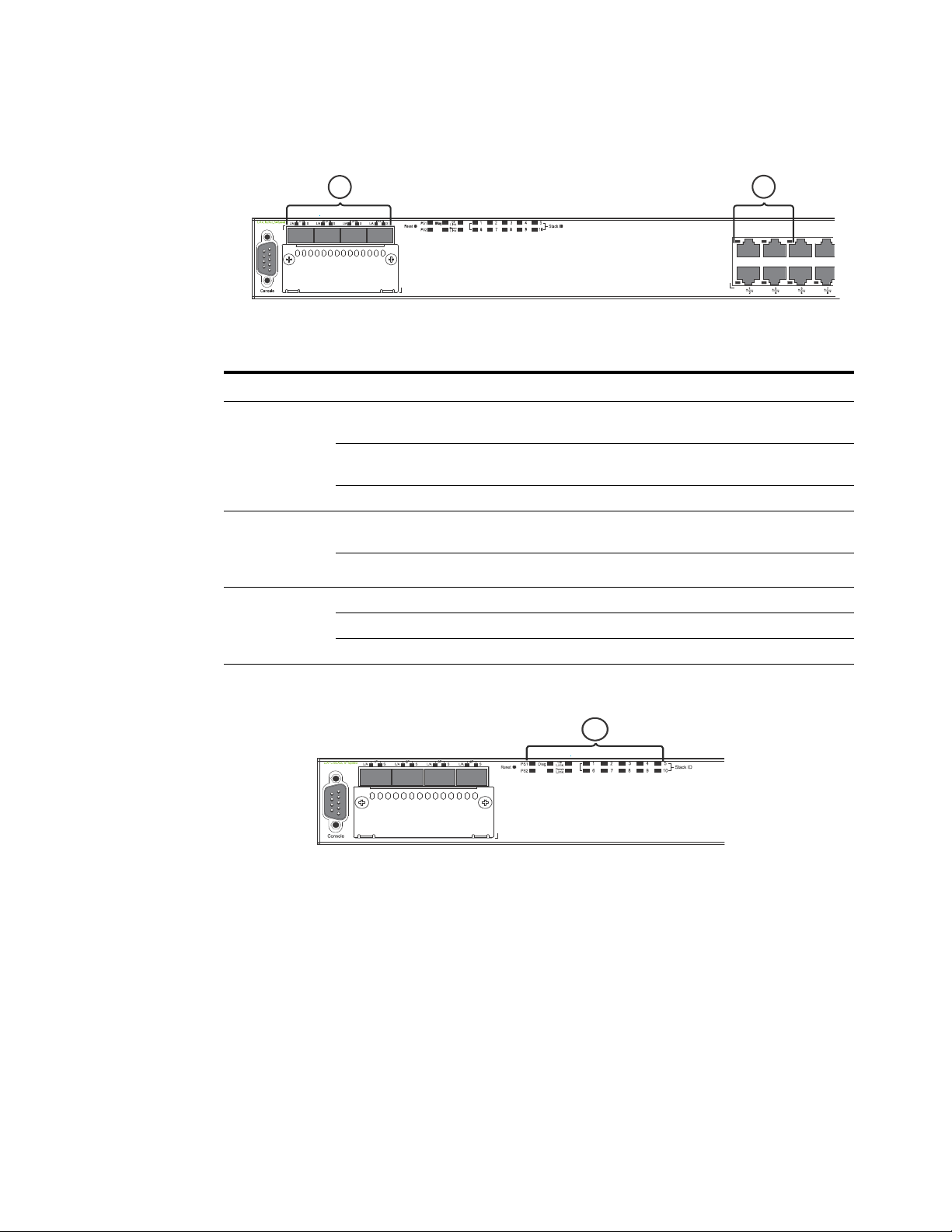
FIGURE 10 Port status LEDs
Slot 3
2
1
A/S
Slot 3
1
A/S
1, 2 Port status LEDs
TABLE 7 Port status LEDs
LED Condition Status
Hardware features
1
Ethernet
On/Flashing Green The port has established a valid link at 1000 Mbps. Flashing
(1~24/48)
Link or
Activity or Speed
On/Flashing Amber The port has established a valid link at 10 or 100 Mbps. Flashing
Off A link is not established with a remote port.
SFP
On/Flashing Green The SFP port has established a valid link. Flashing indicates the
(1F~4F)
Link or
Activity
SFP
(1F~4F)
Speed
Off A link is not established with a remote port.
On Green The SFP port is operating at 1000 Mbps.
On Amber The SFP port is operating at 100 Mbps.
Off A link is not established with a remote port.
FIGURE 11 System status LEDs
indicates the port is transmitting and receiving user packets.
indicates the port is transmitting and receiving user packets.
port is transmitting and receiving user packets.
1System status LEDs
PowerConnect B-FCX Switch Hardware Installation Guide 9
53-1002267-01
Page 20
Hardware features
1
1
TABLE 8 System status LEDs
LED Condition Status
PS1
PS2
(Power Supply
Status)
Diag
(Diagnostic)
A or S
(Active or Standby)
Up Link or Down
Link (Stacking
uplink or downlink
port status)
Stack ID (1-8) Green Indicates the device stack ID.
Green Power supply is operating normally.
Amber Power supply fault.
Off Power off or failure.
Flashing Green System self-diagnostic test in progress.
Green System self-diagnostic test successfully completed.
Amber System self-diagnostic test has detected a fault. (Blower, thermal or any
interface fault.)
Green The device is the Active controller. If this LED is flashing green, the
system is initializing.
Amber Indicates the device is the Standby controller.
Off Device is operating as a stack member, or is in standalone mode.
Green Uplink is operating normally.
Off Uplink has failed or there is no link.
FIGURE 12 Power status LEDs
1Power status LEDs
TABLE 9 Power status LEDs
LED Condition Status
DC OK Green DC output ok
Red DC output fail
AC OK Green AC input ok
Off AC input fail
10 PowerConnect B-FCX Switch Hardware Installation Guide
53-1002267-01
Page 21
Hardware features
NOTE
1357911 131517192123
2 4 6 8 10 12 14 16 18 20 22 24
Reset
1PS2 Diag
Console
Mgmt
1
2
Both “AC OK” and “DC OK” LEDs must be green for the device to function normally.
TABLE 10 Switch status for two installed power supply units
State LED PSU1 PSU2 Switch Status Load Sharing
1
Four Green PSU
LEDs
Single Red ‘DC
OK’ LED
Both ‘DC OK’
LEDs Red
One PSU with
both ‘AC OK’ ‘DC
OK’ LEDs Off
‘DC OK’ LEDs Red
and Off
All ‘AC OK’ LEDs
Off
AC OK Green Green Running Yes
DC OK Green Green
AC OK Green Green Running No
DC OK Green Red
AC OK Green Green Failure No
DC OK Red Red
AC OK Green Off Running No
DC OK Green Off
AC OK Green Off Failure No
DC OK Red Off
AC OK Off Off Power Off or
DC OK Off Off
Failure
No
Port, system, and power status LEDs for PowerConnect B-FCX624 and PowerConnect B-FCX648
PowerConnect B-FCX switches include a display panel for key system and port indicators that
simplifies installation and network troubleshooting. The LEDs, which are located on the front panel
for easy viewing, are shown below and described in the following tables.
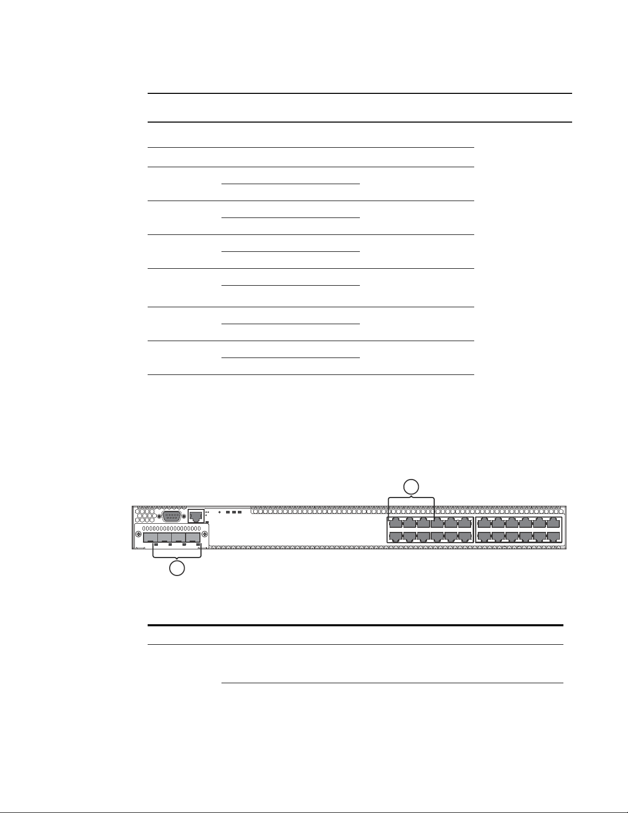
FIGURE 13 Port status LEDs
1 Port status LEDs 2 SFP or SFP+ port status LEDs
TABLE 11 Port status LEDs
LED Condition Status
Ethernet
(1~24/48)
Link or
Activity or Speed
On/Flashing Green The port has established a valid link at 10/100/1000 Mbps.
Flashing indicates the port is transmitting and receiving user
packets.
Off A link is not established with a remote port.
PowerConnect B-FCX Switch Hardware Installation Guide 11
53-1002267-01
Page 22
Hardware features
Reset
1PS2 Diag
Console
Mgmt
1
1
TABLE 11 Port status LEDs (Continued)
LED Condition Status
SFP
(1F~4F)
Link or
Activity
SFP+
(1F~4F)
Link or
Activity
On/Flashing Green The SFP port has established a valid 100/1000 Mbps link.
Flashing indicates the port is transmitting and receiving user
packets.
Off A link is not established with a remote port.
On/Flashing Green The SFP+ port has established a valid 10 Gbps link. Flashing
indicates the port is transmitting and receiving user packets.
Off A link is not established with a remote port.
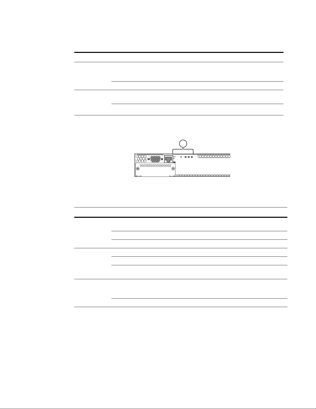
FIGURE 14 System status LEDs
1System status LEDs
TABLE 12 System status LEDs
LED Condition Status
PS1
PS2
(Power Supply
Status)
Diag
(Diagnostic)
Out-of-band
Management
Link or Activity
Green Power supply is operating normally. It is installed properly and the
power cord is attached to a power source.
Amber Power supply fault. The power supply may not be installed properly.
Off Power off or failure.
Flashing Green System self-diagnostic test in progress.
Green System self-diagnostic test successfully completed.
Amber System self-diagnostic test has detected a fault. (Blower, thermal or
any interface fault.)
On/Flashing Green The port has established a valid link at 10/100/1000 Mbps.
Flashing indicates the port is transmitting and receiving user
packets.
Off A link is not established with a remote port.
12 PowerConnect B-FCX Switch Hardware Installation Guide
53-1002267-01
Page 23

FIGURE 15 Power status LEDs
NOTE
1
1Power status LEDs
TABLE 13 Power status LEDs
LED Condition Status
DC OK Green DC output ok
Red DC output fail
AC OK Green AC input ok
Off AC input fail
Hardware features
1
Both “AC OK” and “DC OK” LEDs must be green for the device to function normally.
TABLE 14 Switch status for two installed power supply units
State LED PSU1 PSU2 Switch Status Redundancy
Four Green PSU
LEDs
Single Red ‘DC
OK’ LED
Both ‘DC OK’
LEDs Red
One PSU with
both ‘AC OK’ ‘DC
OK’ LEDs Off
‘DC OK’ LEDs Red
and Off
All ‘AC OK’ LEDs
Off
AC OK Green Green Running Yes
DC OK Green Green
AC OK Green Green Running No
DC OK Green Red
AC OK Green Green Failure No
DC OK Red Red
AC OK Green Off Running No
DC OK Green Off
AC OK Green Off Failure No
DC OK Red Off
AC OK Off Off Power Off or
DC OK Off Off
Failure
No
Power supplies
The device has two power receptacles on the rear panel. Each device ships with one power supply
installed. PowerConnect B-FCX624s, PowerConnect B-FCX648s, PowerConnect B-FCX624, and
PowerConnect B-FCX648 devices use a 210W PSU.
PowerConnect B-FCX Switch Hardware Installation Guide 13
53-1002267-01
Page 24
Hardware features
1
1
1
Each power supply has one standard power receptacle for the AC power cable, and AC and DC
status LEDs for easy monitoring and troubleshooting.
A secondary power supply can be installed to provide backup power in case of a failure and for
load-balancing when both power suppies are operational.Load-balancing gives the power supplies
a longer life span. 210W PSU is hot-swappable.
For instructions on installing and replacing a power supply refer to “Installing and replacing a power
supply unit” on page 26. For information on LED status refer to Table 9.
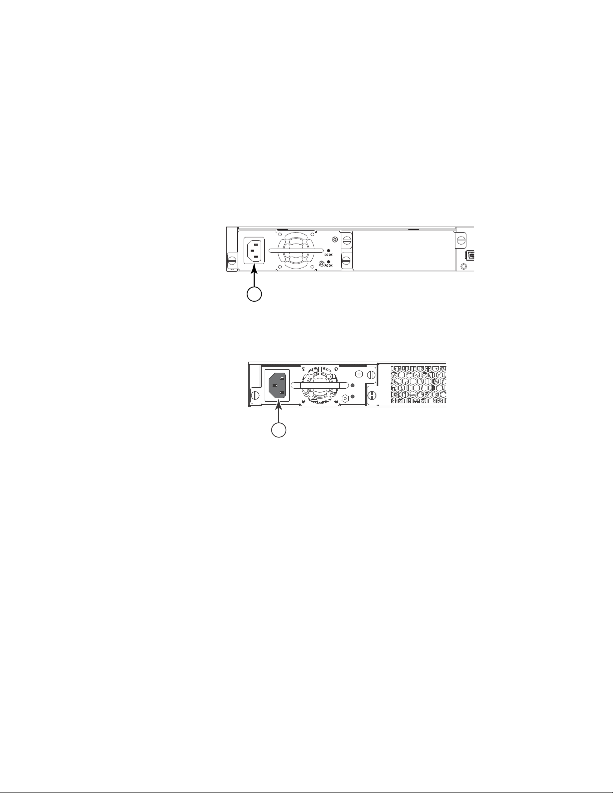
FIGURE 16 PowerConnect B-FCX624s and PowerConnect B-FCX648s AC power supply receptacle
1 AC power receptacle
FIGURE 17 PowerConnect B-FCX624 and PowerConnect B-FCX648 AC power supply receptacle
1 AC power receptacle
Power supply unit operation
When only one PSU is installed, both "AC OK" and "DC OK" LEDs on the installed PSU must be green
for the PowerConnect B-FCX device to function normally.
When two PSUs are installed, both "AC OK" and "DC OK" LEDs for one of the installed PSUs must be
green for the PowerConnect B-FCX device to function normally.
14 PowerConnect B-FCX Switch Hardware Installation Guide
53-1002267-01
Page 25
Chapter
CAUTION
CAUTION
Installing the PowerConnect B-FCX Switch
The procedures in this manual are intended for qualified service personnel.
Before beginning the installation, see the precautions in “Power precautions” on page 17.
Unpacking the device
PowerConnect B-FCX devices ship with all of the items listed below. Verify the contents of your
shipping container. If any items are missing, please contact the place of purchase.
2
Package contents
The following items are included in your shipping carton:
• PowerConnect B-FCX device
• 115V AC PDU power cords(C13- C14) (for AC sourced devices)
• PowerConnect B-FCXs devices ship with a .5M CX-4 stacking cable
• Rack mount kit
• Document Kit
• Rubber feet Kt
• Retainer nuts and screws
• Warranty card
• A straight-through EIA or TIA DB-9 serial cable (F/F). If you prefer to build your own cable, see
the pinout information in “Attaching a PC or terminal” on page 25.
General requirements
To manage the system, you need a management station, such as a PC running a terminal
emulation application. Connect the management station to the Console serial port on the switch.
Use the serial connection to perform basic configuration tasks, including assigning an IP address
and network mask to the system. This information is required to manage the system using the Web
management interface or Brocade Network Advisor or using the CLI through Telnet.
PowerConnect B-FCX Switch Hardware Installation Guide 15
53-1002267-01
Page 26

Installation tasks
2
Installation tasks
Follow the steps listed in Table 15 to install your device. Details for each of these steps are
provided on the pages indicated.
TABLE 15 Installation tasks
Task
Number
Task Where to Find More Information
1 Ensure that the physical environment that will host the
device has the proper cabling and ventilation.
2 Install any required optional modules into the switch. “Powering on the system” on page 24
3 Install the Dell device on a desktop, in an equipment rack
(use provided retainer clips and screws).
4 Once the device is physically installed, plug the device into
a nearby power source that adheres to the regulatory
requirements outlined in this manual.
5 Attach a terminal or PC to the Dell device. This will enable
you to configure the device through the Command Line
Interface (CLI).
6 No default password is assigned to the CLI. For additional
access security, assign a password.
7 Before attaching equipment to the device, you need to
configure an interface IP address to the subnet on which it
will be located. Initial IP address configuration is
performed using the CLI with a direct serial connection.
Subsequent IP address configuration can be performed
using the Web management interface.
8 Once you power on the device and assign IP addresses,
the system is ready to accept network equipment.
9 Test IP connectivity to other devices by pinging them and
tracing routes.
10 Continue configuring the device using the CLI or the Web
management interface. You also can use Brocade
Network Advisor to manage the device.
11 Secure access to the device. PowerConnect B-FCX Series Configuration
“Preparing the installation site” on
page 18
“Installing the device” on page 19
“Powering on the system” on page 24
“Attaching a PC or terminal” on page 25
“Assigning permanent passwords” on
page 33
“Configuring IP addresses” on page 35
“Configuring IP parameters for devices
running Layer 3 software” on page 37
“Testing connectivity” on page 43
PowerConnect B-FCX Series Configuration
Guide
Guide
Installation precautions
Follow all precautions when installing a Dell device.
16 PowerConnect B-FCX Switch Hardware Installation Guide
53-1002267-01
Page 27
General precautions
CAUTION
CAUTION
CAUTION
CAUTION
CAUTION
CAUTION
CAUTION
All fiber-optic interfaces use Class 1 lasers.
Installation precautions
2
Do not install the device in an environment where the operating ambient temperature might
exceed 40
Make sure the air flow around the front and sides of the device is not restricted.
Never leave tools inside the device.
C (104
F).
Lifting precautions
Make sure the rack or cabinet housing the device is adequately secured to prevent it from
becoming unstable or falling over.
Power precautions
Use a separate branch circuit for each AC power cord, which provides redundancy in case one of
the circuits fails.
To avoid high voltage shock, do not open the device while the power is on.
PowerConnect B-FCX Switch Hardware Installation Guide 17
53-1002267-01
Page 28

Preparing the installation site
CAUTION
CAUTION
CAUTION
2
Ensure that the device does not overload the power circuits, wiring, and over-current protection.
To determine the possibility of overloading the supply circuits, add the ampere (amp) ratings of all
devices installed on the same circuit as the device. Compare this total with the rating limit for the
circuit. The maximum ampere ratings are usually printed on the devices near the input power
connectors.
Disconnect the power cord from all power sources to completely remove power from the device.
If the installation requires a different power cord than the one supplied with the device, make
sure you use a power cord displaying the mark of the safety agency that defines the regulations
for power cords in your country. The mark is your assurance that the power cord can be used
safely with the device.
Preparing the installation site
Cabling infrastructure
Ensure that the proper cabling is installed at the site. Refer to “Hardware Specifications” on
page 57 for a summary of supported cabling types and their specifications.
Installation location
Before installing the device, plan its location and orientation relative to other devices and
equipment. Switches can be mounted in a standard 19-inch equipment rack that meets EIA-310D
standards, or on a flat surface. Be sure to follow the guidelines below when choosing a location.
The site should meet the following requirements:
• Maintain temperatures within 0 to 40
non-condensing.
• Allow a minimum of 3 in. of space between the sides and the back of the device and walls or
other obstructions for proper air flow.
• Allow at least 3 in. of space at the front and back of the device for the twisted-pair, fiber-optic,
and power cabling.
• Be accessible for installing, cabling and maintaining the devices.
• Allow the status LEDs to be clearly visible.
• Allow for twisted-pair cable to be always routed away from power lines, fluorescent lighting
fixtures and other sources of electrical interference, such as radios and transmitters.
C (32 to 104F) and humidity levels within 5% to 95%,
18 PowerConnect B-FCX Switch Hardware Installation Guide
53-1002267-01
Page 29
Preparing the installation site
CAUTION
2
• Allow for the unit to be connected to a separate grounded power outlet that provides 110 to
240 VAC, 50 to 60 Hz, is within 2 m (6.6 feet) of each device and is powered from an
independent circuit breaker. As with any equipment, a filter or surge suppressor is
recommended.
Installing the device
You can install Dell devices on a desktop or in an equipment rack, use appropriate retainer nuts
and screws provided.
Make sure the rack or cabinet housing the device is adequately secured to prevent it from
becoming unstable or falling over.
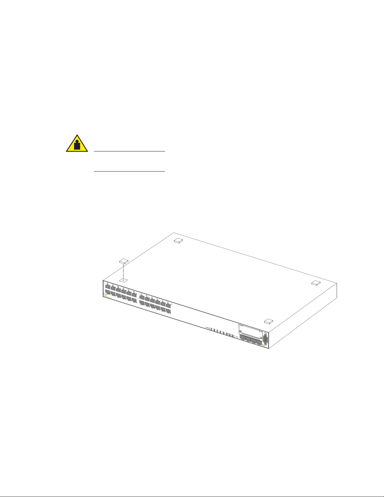
Desktop installation
FIGURE 18 Attaching the adhesive feet
1. Attach the four adhesive feet to the bottom of the first switch.
2. Set the device on a flat desktop, table, or shelf near an AC power source. Make sure that
adequate ventilation is provided for the system. A 3 inch clearance is recommended on each
side.
3. If installing a single switch only, refer to “Powering on the system” on page 24.
4. If installing multiple switches, attach the adhesive feet to each one. Place each device squarely
on top of the one below, in any order.
PowerConnect B-FCX Switch Hardware Installation Guide 19
53-1002267-01
Page 30
Preparing the installation site
NOTE
NOTE
NOTE
2
Rack mount installation
You need a #2 Phillips screwdriver for installation.
For additional support for the stack of switches, refer to the Dell 1U shelf, Dell part number-G118R,
which is ordered separately.
Before mounting the switch in a rack, pay particular attention to the following factors:
• Temperature: Since the temperature within a rack assembly may be higher than the ambient
• Mechanical loading: Do not place any equipment on top of a rack-mounted unit.
• Circuit overloading: Be sure that the supply circuit to the rack assembly is not overloaded.
• Grounding: Rack-mounted equipment should be properly grounded. Particular attention should
Use the following setps to mount devices in rack.
room temperature, check that the rack-environment temperature is within the specified
operating temperature range. (Refer to “Operating Environment” on page 57.)
be given to supply connections other than direct connections to the mains.
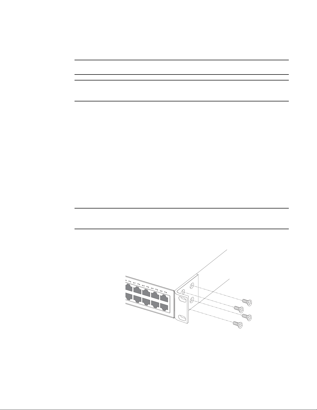
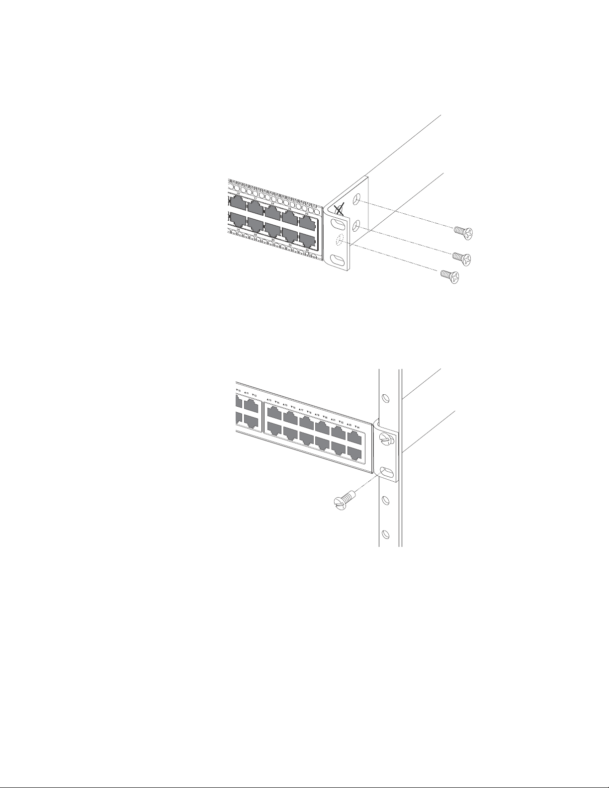
1. Remove the rack mount kit from the shipping carton. The kit contains two L-shaped mounting
brackets and mounting screws.
2. Attach the mounting brackets to the sides of the device as illustrated in Figure 19 and
Figure 20.
PowerConnect B-FCX624 and PowerConnect B-FCX648 brackets are mounted using three screws,
as shown in Figure 20.
FIGURE 19 Attaching the Brackets for PowerConnect B-FCX624s and PowerConnect B-FCX648s
20 PowerConnect B-FCX Switch Hardware Installation Guide
53-1002267-01
Page 31
Preparing the installation site
FIGURE 20 Attaching the brackets for PowerConnect B-FCX624 and PowerConnect B-FCX648
3. Install retainer nuts into the non-threaded holes. And use 10-32 screws to fasten brackets into
the rack. Attach the device in the rack as illustrated in Figure 21.
FIGURE 21 Installing the device in a rack
2
4. If installing a single switch only, proceed to “Powering on the system” on page 24.
5. If installing multiple switches, mount them in the rack, one below the other, in any order.
Connecting devices in a stack
PowerConnect B-FCX624s and PowerConnect B-FCX648s devices
Figure 5 shows how the stack cables are connected between switches in a stack. The connection is
based on 10G/16G Gigabit Ethernet, using CX4 cables. PowerConnect B-FCX devices support
linear and ring stack topologies, and can also operate as standalone devices.
PowerConnect B-FCX Switch Hardware Installation Guide 21
53-1002267-01
Page 32

Preparing the installation site
2
In a linear stack topology there is a single stack cable connection between each switch that carries
two-way communications across the stack. In ring stack topology, an extra cable is connected
between the top and bottom switches forming a “ring” or “closed-loop.” The closed-loop cable
provides a redundant path for the stack link, so if one link fails, stack communications can be
maintained. Figure 5 illustrates a ring-topology stacking configuration.
You can form a stack containing up to eight PowerConnect B-FCX units. To connect switches in a
stack, perform the following steps:
1. Plug one end of a stack cable into one of the CX4 stacking ports of the top unit.
2. Plug the other end of the stack cable into one of the stacking ports of the next unit.
3. Repeat steps 1 and 2 for each unit in the stack. Form a simple chain starting with a stacking
4. (Optional) To form a ring stack topology, plug one end of a stack cable into the remaining
FIGURE 22 Connecting switches in a linear (top) and ring (bottom) topology stack
port on the top unit and ending at a stacking port on the bottom unit (stacking up to eight
units).
stacking port on the bottom unit and the other end into the remaining stacking port on the top
unit.
22 PowerConnect B-FCX Switch Hardware Installation Guide
53-1002267-01
Page 33

Preparing the installation site
NOTE
1357911 131517192123
2 4 6 8 10 12 14 16 18 20 22 24
Reset
1PS2Diag
Console
Mgmt
25 27 29 31 33 35 37 39 41 43 45 47
26 28 30 32 34 36 38 40 42
44
46 48
1357911 131517192123
2 4 6 8 10 12 14 16 18 20 22 24
Reset
1PS2 Diag
Console
Mgmt
1357911 131517192123
2 4 6 8 10 12 14 16 18 20 22 24
Reset
1PS2Diag
Console
Mgmt
2
5. One device in the stack will operate as the Active Controller, one will operate as Standby
Controller, with the rest of the units operating as stack members. For information about how to
configure your stack, see the PowerConnect B-FCX Series Configuration Guide.
PowerConnect B-FCX624 and PowerConnect B-FCX648 devices
Figure 23 and Figure 24 show how stacking cables are connected between PowerConnect
B-FCX624 and PowerConnect B-FCX648 devices in a stack. The connection is based on 10 Gbps
SFP+ using LC-LC MM Fiber cables. These devices support linear and ring stack topologies with the
optional SFP+ modules installed, and can also operate in standalone mode.
PowerConnect B-FCX624 and PowerConnect B-FCX648 devices must have a 4-port 10 Gbps SFP+
module (optional) installed to operate in a stack.
Figure 25 shows a stack containing PowerConnect B-FCX624 , PowerConnect B-FCX648 devices
and another PowerConnect B-FCX device. Using PowerConnect B-FCX624 and PowerConnect
B-FCX648 devices in this type of mixed stack requires your to reconfigure the default stacking ports
on the other PowerConnect B-FCX device. For more information, see the FastIron Configuration
Guide.
You can form a stack containing up to eight PowerConnect B-FCX624 and PowerConnect B-FCX648
units. To connect switches in a stack, perform the following steps:
1. Plug one end of an LC-LC MM Fiber cable into one of the SFP+ stacking ports of the top unit.
2. Plug the other end of the cable into one of the stacking ports of the next unit.
3. Repeat steps 1 and 2 for each unit in the stack. Form a simple chain starting with a stacking
port on the top unit and ending at a stacking port on the bottom unit (stacking up to eight
units). See Figure 23
4. (Optional) To form a ring stack topology, plug one end of an LC-LC MM Fiber cable into the
remaining stacking port on the bottom unit and the other end into the remaining stacking port
on the top unit. See Figure 24.
FIGURE 23 Connecting PowerConnect B-FCX624-E and PowerConnect B-FCX648-E devices in a
linear stack topology
PowerConnect B-FCX Switch Hardware Installation Guide 23
53-1002267-01
Page 34

Powering on the system
1357911 131517192123
2 4 6 8 10 12 14 16 18 20 22 24
Reset
1PS2Diag
Console
Mgmt
25 27 29 31 33 35 37 39 41 43 45 47
26 28 30 32 34 36 38 40 42
44
46 48
1357911 131517192123
2 4 6 8 10 12 14 16 18 20 22 24
Reset
1PS2 Diag
Console
Mgmt
1357911 131517192123
2 4 6 8 10 12 14 16 18 20 22 24
Reset
1PS2Diag
Console
Mgmt
1357911 131517192123
2 4 6 8 10 12 14 16 18 20 22 24
Reset
1PS2 Diag
Console
Mgmt
25 27 29 31 33 35 37 39 41 43 45 47
26 28 30 32 34 36 38 40 42
44
46 48
1357911 131517192123
2 4 6 8 10 12 14 16 18 20 22 24
Reset
1PS2Diag
Console
Mgmt
FastIron FCX648S
2
FIGURE 24 Connecting PowerConnect B-FCX624-E and PowerConnect B-FCX648-E devices in a
ring stack topology
FIGURE 25 Connecting PowerConnect B-FCX624-E and PowerConnect B-FCX648-E devices in a
mixed stack with an PowerConnect B-FCX624s device
Powering on the system
After you complete the physical installation, you can power on the system.
1. Remove the power cable from the shipping package.
2. Attach the AC power cable to the AC connector on the rear panel.
3. Insert the power cable plug into a 115V, 120V, or 240V outlet.
24 PowerConnect B-FCX Switch Hardware Installation Guide
53-1002267-01
Page 35

NOTE
To turn the system off, simply unplug the power cable or cables.
NOTE
NOTE
NOTE
The socket should be installed near the equipment and should be easily accessible.
If the outlet is not rated 115/120V, stop and get the appropriate cable for the outlet.
Attaching a PC or terminal
To assign an IP address, you must have access to the Command Line Interface (CLI). The CLI is a
text-based interface that can be accessed through a direct serial connection to the device and
through Telnet connections. The CLI is described in detail in the PowerConnect B-FCX Series
Configuration Guide.
Access the CLI by attaching a serial cable to the Console port. After you assign an IP address, you
can access the system through Telnet, the Web management interface, or Brocade Network
Advisor.
Attaching a PC or terminal
2
Use the following steps to attach a management station to the serial port.
1. Connect a PC or terminal to the serial port of the system using a straight-through cable. The
serial port has a male DB-9 connector. See Figure 26.
You need to run a terminal emulation program on the PC.
2. Launch the terminal emulation program and set the following session parameters:
• Baud: 9600 bps
• Data bits: 8
• Parity: None
• Stop bits: 1
• Flow control: None
The EIA or TIA 232 serial communication port serves as a connection point for management by a
PC or SNMP workstation. Dell devices come with a standard male DB-9 connector, shown in
Figure 26.
PowerConnect B-FCX Switch Hardware Installation Guide 25
53-1002267-01
Page 36
Installing and replacing a power supply unit
NOTE
CAUTION
2
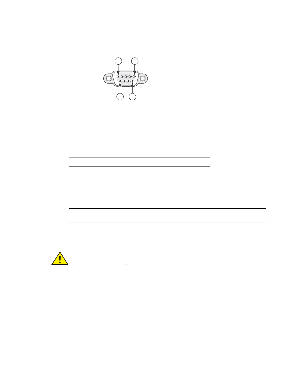
FIGURE 26 Serial Port (DB-9 DTE) Pin-Out
Most PC serial ports also require a cable with a female DB-9 connector. Terminal connections will
vary, requiring either a DB-9 or DB-25 connector, male or female. Serial cable options between a
Dell device and a PC or terminal are shown in Table 16 .
Wiring map for serial cable
TABLE 16 Serial cable wiring
Switch 9-Pin Serial Port Null Modem PC 9-Pin DTE Port
15
6 9
2 TXD (transmit data) ----------------------------> 2 RXD (receive data)
3 RXD (receive data) <---------------------------- 3 TXD (transmit data)
5 SGND (signal ground) <--------------------------> 5 SGND (signal
ground)
No other pins are used.
As indicated in Tab le 16, some of the wires should not be connected.
Installing and replacing a power supply unit
For the PowerConnect B-FCX624 and PowerConnect B-FCX648 devices,be sure that the airflow
direction of the power supply unit matches that of the installed fan tray. The power supplies and
fan trays are clearly labeled with either a green arrow with an “E”, or an orange arrow with an “I”
as shown in Tab le 1 on page 3.
26 PowerConnect B-FCX Switch Hardware Installation Guide
53-1002267-01
Page 37

Installing and replacing a power supply unit
CAUTION
FIGURE 27 Installing a power supply unit
Use the following steps to install a power supply unit in the switch.
1. Remove the blank metal plate (or a previously installed PSU) from the appropriate slot by
removing the two screws with a flat-head screwdriver.
2
2. Before opening the package that contains the PSU, touch the bag to the switch casing to
discharge any potential static electricity. Dell recommends using an ESD wrist strap during
installation.
3. Remove the PSU from the anti-static shielded bag.
4. Holding the PSU level, guide it into the carrier rails on each side and gently push it all the way
into the slot, ensuring that it firmly engages with the connector.
5. When you are sure the PSU has properly engaged the connector, tighten the retainer screws to
secure the in PSU the slot.
When the device is powered on, the PSU AC and DC LEDs on the PSU back panel should turn green
to confirm that the PSU is correctly installed and supplying power.
If you do not install a PSU in a slot, you must keep the slot panel in place. If you run the device
with an uncovered slot, the system will overheat.
PowerConnect B-FCX Switch Hardware Installation Guide 27
53-1002267-01
Page 38
Installing or replacing fan trays on PowerConnect B-FCX624s and PowerConnect B-FCX648s devices
NOTE
CAUTION
2
Installing or replacing fan trays on PowerConnect B-FCX624s and
PowerConnect B-FCX648s devices
FIGURE 28 Installing a fan tray on a PowerConnect B-FCX624s or PowerConnect B-FCX648s
device
Perform the following steps to install a fan tray in the switch.
1. Remove the installed fan tray from the slot by removing the two screws with a crosshead or
Philips screwdriver.
2. Before opening the package that contains the new fan tray, touch the bag to the switch casing
to discharge any potential static electricity. It is recommended that you wear an ESD wrist strap
during installation.
3. Remove the fan tray from the anti-static shielded bag.
4. Holding the fan tray level, guide it into the carrier rails on each side and gently push it all the
way into the slot, ensuring that it firmly engages with the connector.
5. When you are sure the fan tray has properly engaged the connector, tighten the retainer screws
to secure the fan tray in the slot.
The fans are controlled by software, and their speed is set according to the environmental
temperature surrounding the switch.
Installing or replacing fan trays on PowerConnect B-FCX624 and PowerConnect B-FCX648 devices
For PowerConnect B-FCX624 and PowerConnect B-FCX648 devices, be sure that the airflow
direction of the power supply unit matches that of the installed fan tray. The power supplies and
fan trays are clearly labeled with either a green arrow with an “E”, or an orange arrow with an “I”
as shown in Tab le 1 on page 3.
28 PowerConnect B-FCX Switch Hardware Installation Guide
53-1002267-01
Page 39

Installing or replacing fan trays on PowerConnect B-FCX624 and PowerConnect B-FCX648 devices
NOTE
FIGURE 29 Installing a fan tray on a PowerConnect B-FCX624-E, PowerConnect B-FCX624-I,
PowerConnect B-FCX648-E, and PowerConnect B-FCX648-I device
Fan trays are hot-swappable. Perform the following steps to install a fan tray in the switch.
2
1. Remove the installed fan tray from the slot by removing the two screws with a crosshead or
Philips screwdriver.
2. Before opening the package that contains the new fan tray, touch the bag to the switch casing
to discharge any potential static electricity. It is recommended that you wear an ESD wrist strap
during installation.
3. Remove the fan tray from the anti-static shielded bag.
4. Holding the fan tray level, guide it into the carrier rails on each side and gently push it all the
way into the slot, ensuring that it firmly engages with the connector.
5. When you are sure the fan tray has properly engaged the connector, tighten the retainer screws
to secure the fan tray in the slot.
The fans are controlled by software, and their speed is set according to the environmental
temperature surrounding the switch.
PowerConnect B-FCX Switch Hardware Installation Guide 29
53-1002267-01
Page 40

Installing an optional module on PowerConnect B-FCX624s or PowerConnect B-FCX648s devices
CAUTION
2
Installing an optional module on PowerConnect B-FCX624s or
PowerConnect B-FCX648s devices
FIGURE 30 Installing an optional module
PowerConnect B-FCX624s and PowerConnect B-FCX648s switches support an optional two-port 10
Gbps Ethernet XFP module.
Perform these steps to install an optional module.
1. Remove the blank metal plate (or an installed module) from the slot by removing the two
screws with a Phillips screwdriver.
2. Before opening the package that contains the module, touch the bag to the switch casing to
discharge any potential static electricity. It is recommended that you wear an ESD wrist strap
during installation.
3. Remove the module from the anti-static shielded bag.
4. Holding the module level, guide it into the carrier rails on each side and gently push it all the
way into the slot, ensuring that it firmly engages with the connector.
5. When you are sure the module has properly engaged the connector, tighten the retainer
screws to secure the module in the slot.
6. When the switch is powered on, the LEDs will function as described in “Port, system, and
power status LEDs for PowerConnect B-FCX624s and PowerConnect B-FCX648s” on page 8.
If you do not install a module in a slot, you must keep the slot panel in place. If you run the device
with an uncovered slot, the system will overheat.
30 PowerConnect B-FCX Switch Hardware Installation Guide
53-1002267-01
Page 41

Installing an optional module in PowerConnect B-FCX624 and PowerConnect B-FCX648 devices
CAUTION
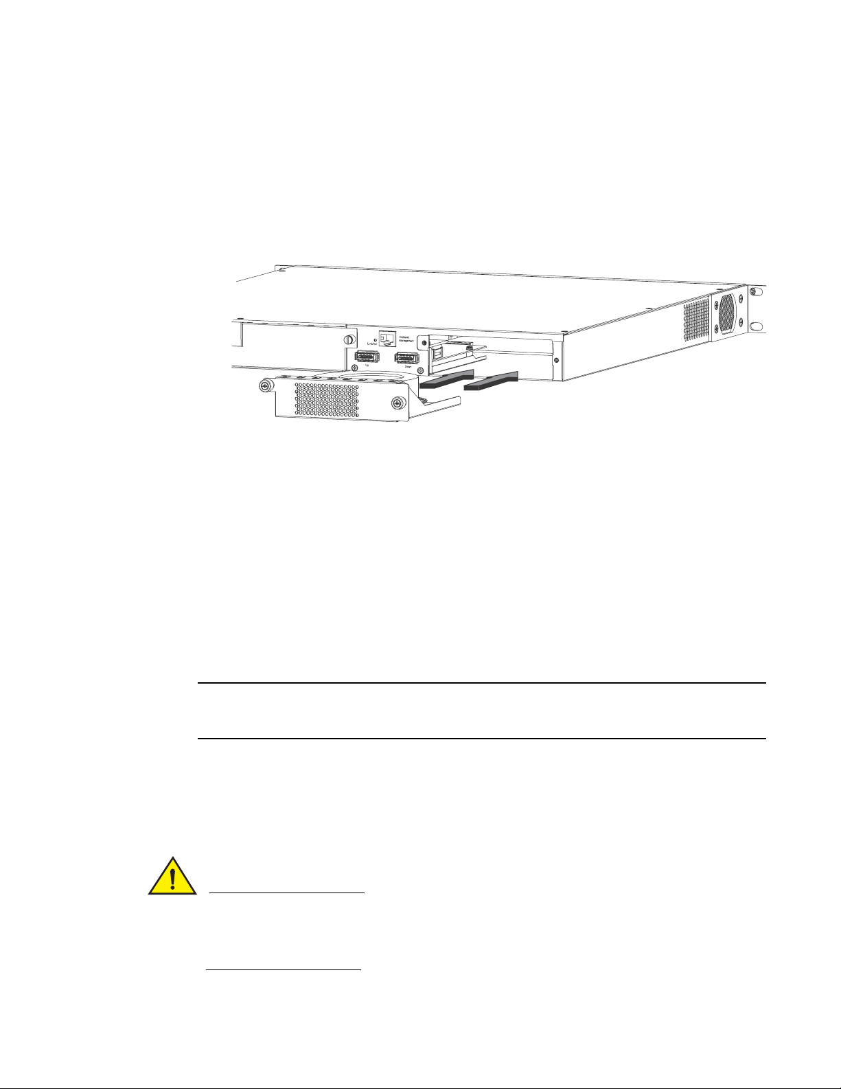
NOTE
Installing an optional module in PowerConnect B-FCX624 and
PowerConnect B-FCX648 devices
PowerConnect B-FCX624 and PowerConnect B-FCX648 switches support an optional four-port 1
Gbps SFP module or four-port 10 Gbps SFP+ module. The 10 Gbps SFP+ module allows you to use
your device in a stack. Figure 31 shows how to install an optional SFP or SFP+ module.
FIGURE 31 Installing an optional module in PowerConnect B-FCX624-E, PowerConnect
B-FCX624-I, PowerConnect B-FCX648-E, and PowerConnect B-FCX648-I devices
2
Optional SFP and SFP+ modules are not hot-swappable. Be sure to power-down your device
before you install or replace a module.
Perform these steps to install an optional module.
1. Remove the blank metal plate (or a installed module) from the slot by removing the two screws
with a Phillips screwdriver.
2. Before opening the module package, touch the bag to the switch casing to discharge any static
electricity. It is recommended that you wear an ESD wrist strap during installation.
3. Remove the module from the anti-static shielded bag.
4. Hold the module level, guide it into the carrier rails and gently push it into the slot until it firmly
engages with the connector.
5. When the module is engaged, tighten the retainer screws to secure the module in the slot.
6. When the switch is powered on, the LEDs will follow the LED status as described in “Port,
system, and power status LEDs for PowerConnect B-FCX624 and PowerConnect B-FCX648” on
page 11.
If you want ports 1 and 2 on the 10 Gbps module to pass regular Ethernet traffic, you must first
disable stacking on these ports. For more information, see the PowerConnect B-FCX Series
Configuration Guide
PowerConnect B-FCX Switch Hardware Installation Guide 31
53-1002267-01
Page 42

Installing an optional module in PowerConnect B-FCX624 and PowerConnect B-FCX648 devices
CAUTION
2
If you do not install a module in a slot, you must keep the slot panel in place. If you run the device
with an uncovered slot, the system will overheat.
32 PowerConnect B-FCX Switch Hardware Installation Guide
53-1002267-01
Page 43

Chapter
CAUTION
NOTE
NOTE
Checking Network Devices and Testing Connectivity
The procedures in this manual are for qualified service personnel.
Assigning permanent passwords
By default, the CLI is not protected by passwords. To secure CLI access, Dell strongly recommends
assigning passwords. See the PowerConnect B-FCX Series Configuration Guide.
You cannot assign a password using the Web Management Interface. You can assign passwords
using Brocade Network Advisor if an enable password for a Super User has been configured on the
device.
The CLI contains the following access levels:
3
• User EXEC – The level you enter when you first start a CLI session. At this level, you can view
some system information but you cannot configure system or port parameters.
• Privileged EXEC – This level is also called the Enable level and can be secured by a password.
You can perform tasks such as manage files on the flash module, save the system
configuration to flash, and clear caches at this level.
• CONFIG – The configuration level. This level lets you configure the system IP address and
configure switching and routing features. To access the CONFIG mode, you must already be
logged into the Privileged level of the EXEC mode.
You can set the following levels of Enable passwords:
• Super User – Allows complete read-and-write access to the system. This is generally for system
administrators and is the only password level that allows you to configure passwords.
You must set a super user password before you can set other types of passwords.
• Port Configuration – Allows read-and-write access for specific ports but not for global
(system-wide) parameters.
• Read Only – Allows access to the Privileged EXEC mode and CONFIG mode but only with read
access.
PowerConnect B-FCX Switch Hardware Installation Guide 33
53-1002267-01
Page 44

Assigning permanent passwords
NOTE
NOTE
NOTE
3
Setting passwords
1. At the opening CLI prompt, enter the following command to change to the Privileged level of the
EXEC mode:
PowerConnect> enable
2. Access the CONFIG level of the CLI by entering the following command:
PowerConnect# configure terminal
PowerConnect(config)#
3. Enter the following command to set the super user password:
PowerConnect(config)# enable super-user-password <text>
You must set the super user password before you can set other types of passwords.
4. Enter the following commands to set the port configuration and read-only passwords:
PowerConnect(config)# enable port-config-password <text>
PowerConnect(config)# enable read-only-password <text>
If you forget your super user password, refer to “Recovering from a lost password” on page 34.
Syntax: enable super-user-password | read-only-password | port-config-password <text>
Passwords can be up to 32 characters long.
Recovering from a lost password
By default, the CLI does not require passwords. However, if someone has configured a password
for the device but the password has been lost, you can regain super user access to the device using
the following procedure.
Recovery from a lost password requires direct access to the serial port and a system reset.
Use the following procedure to recover from a lost password.
1. Start a CLI session over the serial interface to the Dell device.
2. Reboot the device.
3. While the system is booting, before the initial system prompt appears, enter b to enter the boot
monitor mode.
4. Enter no password at the prompt. (You cannot abbreviate this command.)
5. Enter boot system flash primary at the prompt. This command causes the device to bypass the
system password check.
After the console prompt reappears, assign a new password.
34 PowerConnect B-FCX Switch Hardware Installation Guide
53-1002267-01
Page 45

Configuring IP addresses
CAUTION
NOTE
You must configure at least one IP address using the serial connection to the CLI before you can
manage the system using the other management interfaces.
Dell devices support both classical IP network masks (Class A, B, and C subnet masks, and so on)
and Classless Interdomain Routing (CIDR) network prefix masks.
• To enter a classical network mask, enter the mask in IP address format. For example, enter
“209.157.22.99 255.255.255.0” for an IP address with a Class-C subnet mask.
• To enter a prefix number for a network mask, enter a forward slash ( / ) and the number of bits
in the mask immediately after the IP address. For example, enter “209.157.22.99/24” for an
IP address that has a network mask with 24 significant (“mask”) bits.
By default, the CLI displays network masks in classical IP address format (example:
255.255.255.0). You can change the display to the prefix format. See the PowerConnect B-FCX
Series Configuration Guide.
Devices running Layer 2 software
Use the following procedure to configure an IP Address on a device running Layer 2 software.
Configuring IP addresses
3
1. At the opening CLI prompt, enter enable.
PowerConnect> enable
2. Enter the following command at the Privileged EXEC level prompt (for example,
PowerConnect
present:
PowerConnect# erase startup-config
Use the erase startup-config command only for new systems. If you enter this command on a
system you have already configured, the command erases the configuration. If you accidentally
do erase the configuration on a configured system, enter the write memory command to save the
running configuration to the startup-config file.
3. Access the configuration level of the CLI by entering the following command:
PowerConnect# configure terminal (Privileged EXEC Level)
PowerConnect(config)# (Global CONFIG Level)
4. Configure the IP address and mask for the switch.
PowerConnect(config)# ip address 192.22.3.44 255.255.255.0
5. Set a default gateway address for the switch.
PowerConnect(config)# ip default-gateway 192.22.3.1
#), then press Enter. This command erases the factory test configuration if still
You do not need to assign a default gateway address for single subnet networks.
Syntax: enable [<password>]
Syntax: configure terminal
PowerConnect B-FCX Switch Hardware Installation Guide 35
53-1002267-01
Page 46

Configuring IP addresses
CAUTION
NOTE
3
Syntax: [no] ip address <ip-addr> <ip-mask>
or
Syntax: [no] ip address <ip-addr>/<mask-bits>
Syntax: ip default-gateway <ip-addr>
Devices running Layer 3 software
Before attaching equipment to a Layer 3 Switch, you must assign an interface IP address to the
subnet on which the router will be located. You must use the serial connection to assign the first IP
address. For subsequent addresses, you also can use the CLI through Telnet or the Web
management interface.
By default, you can configure up to 24 IP interfaces on each port, virtual interface, and loopback
interface. You can increase this amount to up to 64 IP subnet addresses per port by increasing the
size of the subnet-per-interface table.
The following procedure shows how to add an IP address and mask to a router port.
1. At the opening CLI prompt, enter enable.
PowerConnect> enable
2. Enter the following command at the CLI Privileged EXEC level prompt, then press Enter. This
command erases the factory test configuration if still present:
PowerConnect# erase startup-config
Use the erase startup-config command only for new systems. If you enter this command on a
system you have already configured, the command erases the configuration. If you accidentally
do erase the configuration on a configured system, enter the write memory command to save the
running configuration to the startup-config file.
3. Access the configuration level of the CLI by entering the following command:
PowerConnect# configure terminalPrivileged EXEC Level
PowerConnect(config)#Global CONFIG Level
4. Configure the IP addresses and mask addresses for the interfaces on the router.
PowerConnect(config)# int e 2
PowerConnect(config-if-e1000-2)# ip address 192.22.3.44 255.255.255.0
You can use the syntax ip address <ip-addr>/<mask-bits> if you know the subnet mask length.
In the above example, you could enter ip address 192.22.3.44/24.
Syntax: enable [<password>]
Syntax: configure terminal
Syntax: [no] ip address <ip-addr> <ip-mask> [secondary]
or
Syntax: [no] ip address <ip-addr>/<mask-bits> [secondary]
36 PowerConnect B-FCX Switch Hardware Installation Guide
53-1002267-01
Page 47

Configuring IP addresses
NOTE
NOTE
Use the secondary parameter if you have already configured an IP address within the same
subnet on the interface.
3
Configuring IP parameters for devices running Layer 3 software
This section describes how to configure IP parameters for devices running Layer 3 software.
Configuring IP addresses
You can configure an IP address on the following types of Layer 3 switch interfaces:
• Ethernet port
• Virtual routing interface (also called a Virtual Ethernet or “VE”)
• Loopback interface
By default, you can have up to 24 IP addresses on each interface, but you can increase this number
to 128 IP addresses.
Once you configure a virtual routing interface on a VLAN, you cannot configure Layer 3 interface
parameters on individual ports in the VLAN. Instead, you must configure the parameters on the
virtual routing interface itself.
Dell devices support both classical IP network masks (Class A, B, and C subnet masks, and so on)
and Classless Interdomain Routing (CIDR) network prefix masks.
• To enter a classical network mask, enter the mask in IP address format. For example, enter
“209.157.22.99 255.255.255.0” for an IP address with a Class-C subnet mask.
• To enter a prefix network mask, enter a forward slash ( / ) and the number of bits in the mask
immediately after the IP address. For example, enter “209.157.22.99/24” for an IP address
that has a network mask with 24 significant bits (ones).
By default, the CLI displays network masks in classical IP address format (for example:
255.255.255.0). You can change the display to prefix format.
Assigning an IP address to an Ethernet port
Enter the following commands to assign an IP address to port 1/1/1.
PowerConnect(config)# interface ethernet 1/1/1
PowerConnect(config-if-1/1/1)# ip address 192.45.6.1 255.255.255.0
You also can enter the IP address and mask in CIDR format, as follows:
PowerConnect(config-if-1/1/1)# ip address 192.45.6.1/24
Syntax: [no] ip address <ip-addr> <ip-mask>
or
Syntax: [no] ip address <ip-addr>/<mask-bits>
Assigning an IP address to a loopback interface
Loopback interfaces are always up, regardless of the states of physical interfaces. They can add
stability to the network because they are not subject to route flap problems that can occur due to
unstable links between a Layer 3 Switch and other devices. You can configure up to four loopback
interfaces on a Layer 3 switch.
PowerConnect B-FCX Switch Hardware Installation Guide 37
53-1002267-01
Page 48

Configuring IP addresses
NOTE
NOTE
3
You can add up to 24 IP addresses to each loopback interface.
If you configure the Dellswitch to use a loopback interface to communicate with a BGP4 neighbor,
you must also configure a loopback interface on the neighbor and configure the neighbor to use that
loopback interface to communicate with theDell switch.
To add a loopback interface, enter commands such as those shown in the following example:
PowerConnect(config)# exit
PowerConnect(config)# int loopback 1
PowerConnect(config-lbif-1)# ip address 10.0.0.1/24
Syntax: interface loopback <num>
The <num> parameter specifies the virtual interface number. You can specify from 1 to the
maximum number of virtual interfaces supported on the device. To display the maximum number
of virtual interfaces supported on the device, enter the show default values command. The
maximum is listed in the System Parameters section, in the Current column of the virtual-interface
row.
Assigning an IP address to a virtual routing interface
A virtual interface is a logical port associated with a Layer 3 Virtual LAN (VLAN) configured on a
Layer 3 switch. You can configure routing parameters on the virtual interface to enable the Layer 3
switch to route protocol traffic from one Layer 3 VLAN to the other, without using an external router.
This section describes how to configure an IP address on a virtual interface.
The switch uses the lowest MAC address on the device (the MAC address of port 1 or 1/1/1) as the
MAC address for all ports within all virtual interfaces you configure on the device.
Enter commands similar to the following to add a virtual interface to a VLAN and configure an IP
address on the interface.
PowerConnect(config)# vlan 2 name IP-Subnet_1.1.2.1/24
PowerConnect(config-vlan-2)# untag 1/1/1 to 1/1/4
PowerConnect(config-vlan-2)# router-interface ve1
PowerConnect(config-vlan-2)# interface ve1
PowerConnect(config-vif-1)# ip address 1.1.2.1/24
The first two commands in this example create a Layer 3 protocol-based VLAN name
“IP-Subnet_1.1.2.1/24” and add a range of untagged ports to the VLAN. The router-interface
command creates virtual interface 1 as the routing interface for the VLAN. The last two commands
change to the interface configuration level for the virtual interface and assign an IP address to the
interface.
Syntax: router-interface ve <num>
Syntax: interface ve <num>
Deleting an IP address
Enter a command similar to the following to delete an IP address.
PowerConnect(config-if-1/1/1)# no ip address 1.1.2.1
This command deletes IP address 1.1.2.1. You do not need to enter the subnet mask.
38 PowerConnect B-FCX Switch Hardware Installation Guide
53-1002267-01
Page 49
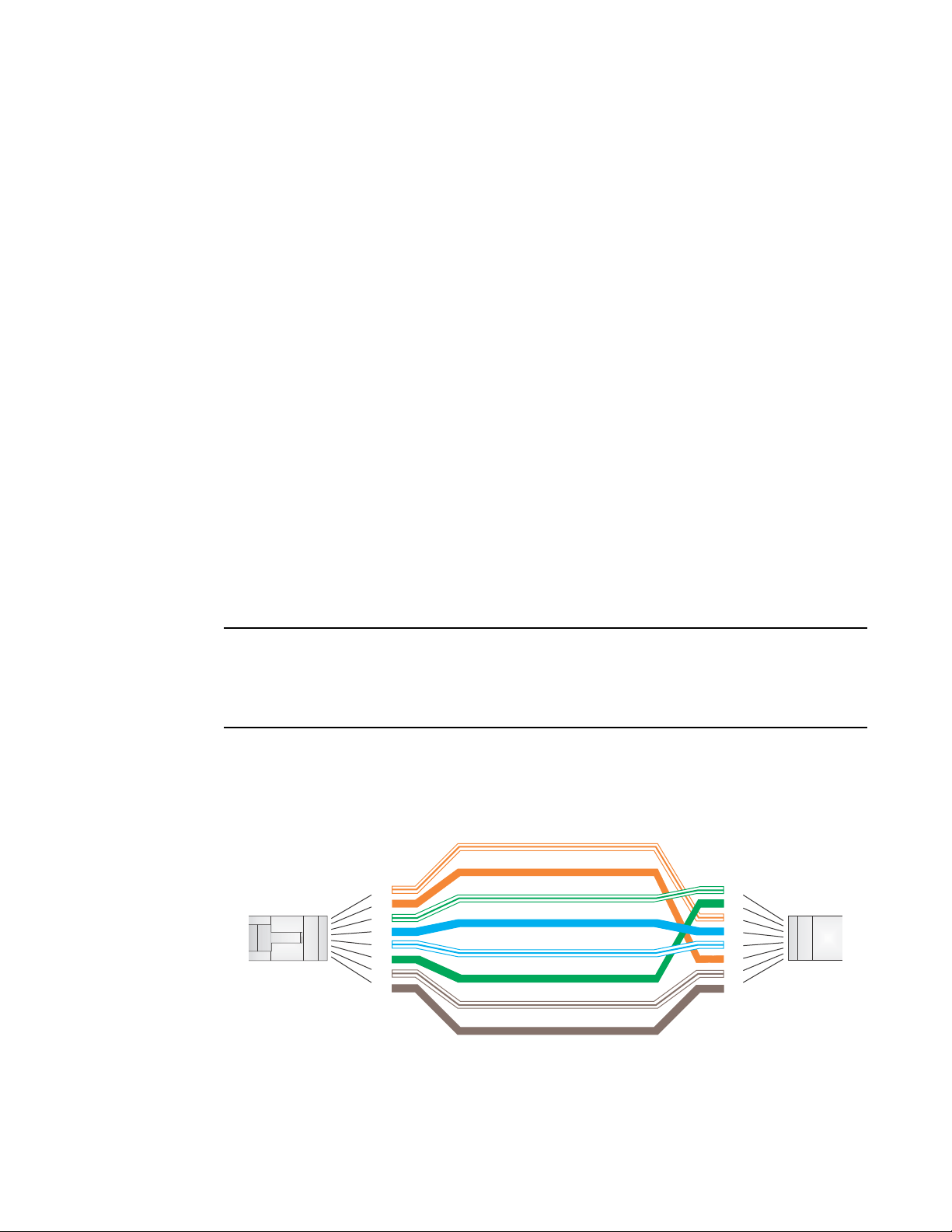
Configuring IP addresses
NOTE
Orange
1
2
3
4
5
6
7
8
1
2
3
4
5
6
7
8
Green
Brown
Blue
White/Orange Stripe
White/Green Stripe
White/Blue Stripe
White/Brown Stripe
End BEnd A
10/100BASE-TX Crossover Cable
3
To delete all IP addresses from an interface, enter the following command:
PowerConnect(config-if-1/1/1)# no ip address *
Syntax: no ip address <ip-addr> | *
Connecting network devices
Dell devices support connections to other vendors’ routers, switches, and hubs, as well other Dell
devices.
Connectors.
For port pinouts, refer to “Pinouts and signalling” on page 61.
Cable specifications
Refer to “Cable specifications” on page 62 for cable lengths and types.
Connecting to Ethernet or fast Ethernet hubs
For copper connections to Ethernet hubs, a 10/100BaseTX or 1000BaseT switch, or another Dell
device, a crossover cable is required (Figure 32 and Figure 33). If the hub is equipped with an
uplink port, it will require a straight-through cable instead of a crossover cable.
The 802.3ab standard (automatic MDI or MDIX detection) calls for automatic negotiation of the
connection between two 1000Base-T ports. In this case a straight-through cable may work just as
well as a crossover cable. For more information about this feature, see the PowerConnect B-FCX
Series Configuration Guide.
FIGURE 32 UTP crossover cable
PowerConnect B-FCX Switch Hardware Installation Guide 39
53-1002267-01
Page 50

Configuring IP addresses
Orange
1
2
3
4
5
6
7
8
1
2
3
4
5
6
7
8
Green
Brown
Blue
White/Orange Stripe
White/Green Stripe
White/Blue Stripe
White/Brown Stripe
End BEnd A
g
10/100BASE-TX Straight-through Cable
3
FIGURE 33 Straight-through cable
Connecting to workstations, servers, or routers
Straight-through UTP cabling is required for direct UTP attachment to workstations, servers, or
routers using network interface cards (NICs).
Fiber cabling is required for direct attachment to Gigabit NICs or switches and routers through fiber
ports. Refer to “Connecting a network device to a fiber port” on page 40.
Automatic MDI or MDIX detection
All 10/100 and Gbps Ethernet Copper ports on the devices support automatic Media Dependent
Interface (MDI) and Media Dependent Interface Crossover (MDIX) detection. This feature is
enabled on all 10/100 and Gigabit copper ports by default. For each port, you can disable auto
MDI or MDIX, designate the port as an MDI port, or designate the port as an MDIX port.
For more information about this feature and how configure it, refer to PowerConnect B-FCX Series
Configuration Guide.
Connecting a network device to a fiber port
For direct attachment from the device to a Gbps NIC, switch, or router, using a fiber optic
transceiver, you will need fiber cabling with an LC connector.
To connect the device to another network device using a fiber port, you must do the following tasks:
• Install a fiber optic transceiver (XFP, SFP, or SFP+)
• Cable the fiber optic transceiver
The following sections describe these tasks.
Fiber Optic transceivers
40 PowerConnect B-FCX Switch Hardware Installation Guide
Tab le 17 lists supported XFP transceivers (for stacking and non-stacking PowerConnect B-FCX
models). Tab le 18 shows supported SFP and SFP+ transceivers. For information about cabling for
transceivers, see Table 24 .
53-1002267-01
Page 51

Configuring IP addresses
NOTE
CAUTION
3
TABLE 17 Supported XFP transceivers for PowerConnect B-FCX624s and PowerConnect
B-FCX648s
10 Gigabit Optic Distance Supported for stacking
10GBase-SR 300m Yes
10GBase-LR 10km No
10GBase-ER 40km No
TABLE 18 Supported SFP transceivers for PowerConnect B-FCX624 and PowerConnect
B-FCX648
10 Gigabit Optic Distance Supported for stacking
10GSFPP-SR 300m Yes
10GSFPP-LR 10km No
Installing a transceiver
You can install a new transceiver in an XFP, SFP, or SFP+ slot while the device is powered on and
running.
While installing a transceiver, wear an ESD wrist strap with a plug for connection to a metal surface.
For safety reasons, the ESD wrist strap should contain a series 1 meg ohm resistor.
All fiber optic interfaces use Class 1 lasers.
Use the following setps to install a transceiver.
1. Put on the ESD wrist strap and ground yourself by attaching the clip end to a metal surface
(such as an equipment rack) to act as ground.
2. Remove the new transceiver from the protective packaging.
3. Gently insert the transceiver into the slot until it clicks into place. Transceivers are keyed to
prevent incorrect insertion.
PowerConnect B-FCX Switch Hardware Installation Guide 41
53-1002267-01
Page 52

Configuring IP addresses
Slot 3
A/S
3
FIGURE 34 Installing a transceiver in PowerConnect B-FCX624s and PowerConnect B-FCX648s
devices
FIGURE 35 Installing a transceiver in PowerConnect B-FCX624 and PowerConnect B-FCX648
Cabling a fiber optic transceiver
Use the following steps to cable a fiber optic transceiver.
1. Remove the protective covering from the fiber-optic port connectors and store the covering for
future use.
2. Before cabling a fiber optic transceiver, Dell strongly recommends cleaning the cable
connectors and the port connectors. For more information, refer to “Cleaning the fiber optic
connectors” on page 43.
42 PowerConnect B-FCX Switch Hardware Installation Guide
3. Gently insert the cable connector (a tab on each connector should face upward) into the
transceiver connector until the tabs lock into place.
4. Observe the link and active LEDs to determine if the network connections are functioning
properly. For more information about the LED indicators, refer to Table 19.
53-1002267-01
Page 53

Cleaning the fiber optic connectors
NOTE
To avoid problems with the connection between the fiber optic transceiver (SFP, SFP+, or
mini-GBIC) and the fiber cable connectors.
When not using an SFP connector, make sure to keep the protective covering in place.
Testing connectivity
Test for connectivity by observing the LEDs related to network connection.
Pinging an IP address
To verify that a PowerConnect B-FCX device can reach another device through the network, enter a
command similar to the following at any level of the CLI.
PowerConnect> ping 192.33.4.7
Syntax: ping <ip addr> [source <ip addr>] [count <num>] [timeout <msec>] [ttl <num>] [verify]
[no-fragment] [quiet] [data <1-to-4 byte hex#, e.g. abcdef00>] [numeric] [size <byte>]
[brief [max-print-per-sec <num 0-2047>]]
Testing connectivity
3
If you address the ping to the IP broadcast address, the device lists the first four responses.
Observing LEDs
After you install the network cables, you can observe certain LEDs to determine if the network
connections are functioning properly. Tab le 19 outlines the LEDs related to the network
connections, the desired state of each LED, possible abnormal states of each LED, and what to do
if an LED indicates an abnormal state.
PowerConnect B-FCX Switch Hardware Installation Guide 43
53-1002267-01
Page 54

Testing connectivity
3
TABLE 19 Network connection-related LED states
LED Desired
State
Ethernet
(1-24/48)
Link or
Activity or
Speed
SFP
(1F~4F)
Link or
Activity
SFP
(1F~4F)
Speed
On or
Blinking
(Green or
Amber)
On Green A link is established with
On (Green
or Amber)
Meaning Abnormal State Meaning or Action
A link is established with
the remote port and user
packets are being
transmitted or received.
Off A link is not established with the remote port. You can do the
following:
• Verify that the connection to the other network device has
been properly made. Also, make certain that the other
network device is powered on and operating correctly.
• Verify that the port has not been disabled through a
configuration change. You can use the CLI. If you have
configured an IP address on the device, you also can use
the Web management interface or Brocade Network
Advisor.
• For the combination ports (ports 1~4), check that the
shared SFP port (1F~4F) is not being used.
• If the other actions don’t resolve the problem, try using a
different port or a different cable.
Off A link is not established with the remote port. You can do the
the remote port.
following:
• Verify that the connection to the other network device has
been properly made. Also, make certain that the other
network device is powered on and operating correctly.
• Verify that the transmit port on the Dell device is
connected to the receive port on the other network device,
and that the receive port on the Dell device is connected
to the transmit port on the other network device. If you are
not certain, remove the two cable connectors from the
port connector and reinsert them in the port connector,
reversing their order.
• Dust may have accumulated in the cable connector or port
connector. For information about cleaning the connectors,
refer to “Cleaning the fiber optic connectors” on page 43.
• Verify that the port has not been disabled through a
configuration change.
• Check that the configuration has not forced the use of the
RJ45 port shared with the SFP port.
• If the other actions don’t resolve the problem, try using a
different port or a different cable.
A link is established with
the remote port.
Off A link is not established with the remote port. You can do the
following:
• Check the Link LED to make sure the link is still
established with the remote port. If not, take the actions
described in the Meaning or Action column for the Link
LED.
44 PowerConnect B-FCX Switch Hardware Installation Guide
53-1002267-01
Page 55

TABLE 19 Network connection-related LED states (Continued)
Troubleshooting network connections
3
LED Desired
State
SFP+
(1F~4F)
Link or
Activity
SFP+
(1F~4F)
Speed
On Green A link is established with
On (Green
or Amber)
Meaning Abnormal State Meaning or Action
Off A link is not established with the remote port. You can do the
the remote port.
following:
• Verify that the connection to the other network device has
been properly made. Also, make certain that the other
network device is powered on and operating correctly.
• Verify that the transmit port on the Dell device is
connected to the receive port on the other network device,
and that the receive port on the Dell device is connected
to the transmit port on the other network device. If you are
not certain, remove the two cable connectors from the
port connector and reinsert them in the port connector,
reversing their order.
• Dust may have accumulated in the cable connector or port
connector. For information about cleaning the connectors,
refer to “Cleaning the fiber optic connectors” on page 43.
• Verify that the port has not been disabled through a
configuration change.
• Check that the configuration has not forced the use of the
RJ45 port shared with the SFP port.
• If the other actions don’t resolve the problem, try using a
different port or a different cable.
A link is established with
the remote port.
Off A link is not established with the remote port. You can do the
following:
• Check the Link LED to make sure the link is still
established with the remote port. If not, take the actions
described in the Meaning or Action column for the Link
LED.
If a problem persists after taking these actions, contact Dell Technical Support.
Tracing a route
To determine the path through which a Dell device can reach another device, enter a command
similar to the following at any level of the CLI on the device.
PowerConnect> traceroute 192.33.4.7
Syntax: traceroute <host-ip-addr> [maxttl <value>] [minttl <value>] [numeric] [timeout <value>]
[source-ip <ip addr>]
The CLI displays trace route information for each hop as soon as the information is received.
Traceroute requests display all responses to a given TTL. In addition, if there are multiple equal-cost
routes to the destination, the Dell device displays up to two responses by default.
Troubleshooting network connections
• For the indicated port, verify that both ends of the cabling (at the device and the connected
device) are snug.
• Verify that the device and the connected device are both powered on and operating correctly.
PowerConnect B-FCX Switch Hardware Installation Guide 45
53-1002267-01
Page 56

Troubleshooting network connections
3
• Verify that you have used the correct cable type for the connection:
- For twisted-pair connections to an end node, use straight-through cabling.
- For fiber optic connections, verify that the transmit port on the device is connected to the
receive port on the connected device, and that the receive port on the device is connected
to the transmit port on the connected device.
• Use the CLI to verify that the port has not been disabled through a configuration change. If you
have configured an IP address on the device, you also can use the Web management interface
or Brocade Network Advisor.
• If the other procedures don’t resolve the problem, try using a different port or a different cable.
Using Virtual Cable Testing to diagnose a cable
These devices support Virtual Cable Test (VCT) technology. VCT technology enables you to diagnose
a conductor (wire or cable) by sending a pulsed signal into the conductor, then examining the
reflection of that pulse. This method of cable analysis is referred to as Time Domain Reflectometry
(TDR). By examining the reflection, the device can detect and report cable statistics such as local
and remote link pair, cable length, and link status.
Configuration notes
• This feature is supported on copper ports only. It is not supported on fiber ports.
• The port to which the cable is connected must be enabled when you issue the command to
diagnose the cable. If the port is disabled, the command is rejected.
• If the port is operating at 100 Mbps half-duplex, the TDR test on one pair will fail.
• If the remote pair is set to forced 100 Mbps, any change in MDI or MDIX may cause the device
to interpret the Multilevel Threshold-3 (MLT-3) as a reflected pulse, in which case, the device
will report a faulty condition. In this case, Dell recommends that you run the TDR test a few
times for accurate results.
Command syntax
To diagnose a cable using TDR, enter a command such as the following at the Privileged EXEC level
of the CLI.
PowerConnect# phy cable-diag tdr 1/1/1
This command diagnoses the cable attached to port 1/1/1.
Syntax: phy cable-diag tdr <port-num>
Viewing the results of the cable analysis
To display the results of the cable analysis, enter a command similar to the following at the
Privileged EXEC level of the CLI.
PowerConnect# show cable-diag tdr 1/1/1
46 PowerConnect B-FCX Switch Hardware Installation Guide
53-1002267-01
Page 57

Troubleshooting network connections
PowerConnect# show cable-diag tdr 1/1/1
Port Speed Local pair Pair Length Remote pair Pair status
--------- ----- ---------- ----------- ----------- ----------1/1/1 1000M Pair A <50M Pair B Terminated
Pair B <50M Pair A Terminated
Pair C <50M Pair D Terminated
Pair D <50M Pair C Terminated
The output from this command appears below.
Syntax: show cable-diag tdr <port-num>
Tab le 20 defines the fields shown in this output.
TABLE 20 Cable statistics
This Line... Displays...
Port The port that was tested.
Speed The current line speed of the port.
Local pair The local link name.
Pair Length The cable length when terminated, or the distance to the point of fault when the line
is not up.
Remote pair The remote link name.
Pair status The status of the link. This field displays one of the following:
• Terminated: The link is up.
• Shorted: A short is detected in the cable.
• Open: An opening is detected in the cable.
• ImpedMis: The impedance is mismatched.
• Failed: The TDR test failed.
3
Digital optical monitoring
You can configure your device to monitor optical transceivers in the system, either globally or by
specified port. When this feature is enabled, the system monitors the temperature and signal
power levels for the optical transceivers in the specified ports. Console messages and syslog
messages are sent when optical operating conditions fall below or rise above the XFP, SFP, and
SFP+ manufacturer’s recommended thresholds. For more information about digital optical
monitoring, refer to PowerConnect B-FCX Series Configuration Guide.
PowerConnect B-FCX Switch Hardware Installation Guide 47
53-1002267-01
Page 58

Troubleshooting network connections
3
48 PowerConnect B-FCX Switch Hardware Installation Guide
53-1002267-01
Page 59

Chapter
CAUTION
Managing the PowerConnect B-FCX Hardware
The procedures in this manual are for qualified service personnel.
Managing temperature settings
This section describes how to display temperature settings on the device and how to change the
temperature warning and shutdown levels.
Using the temperature sensor
The device ships with three built-in temperature sensors that cause the device to generate a Syslog
message and SNMP trap if the temperature exceeds a specified warning level or shutdown level. If
the device temperature exceeds the safe threshold (shutdown level), the device will reboot.
4
The software reads the temperature sensors based on the device poll time, which is by default 60
seconds. If the temperature equals or exceeds the shutdown temperature for five consecutive polls
by the software, the software will reboot the device to prevent damage.
You can use the CLI or Web management interface to perform the following tasks:
• Display the temperature of the device
• Change the warning and shutdown temperature levels
• Change the device poll time
Displaying the temperature
By default, the software polls the temperature sensor every 60 seconds to get the current
temperature. This poll rate is controlled by the device poll time, which also controls how often the
software polls other system components.
To display the temperature of a device, enter the show chassis command at any level of the CLI.
PowerConnect# show chassis
The stack unit 1 chassis info:
Power supply 1 (NA - AC - Regular) present, status ok
Power supply 2 not present
Fan ok, speed (auto):