

Page 1

App Note 177
Programming 1-Wire EPROM and
EEPROM Memory Devices Using a PC
www.maxim-ic.com
INTRODUCTION
Dallas Semiconductor offers hardware/software solutions for programming DS243x series EEPROM and
DS250x series EPROM devices (or the DS197x and DS198x iButton® form factors) in a PC-based
environment. While these devices are commonly programmed in an embedded application, it is often
desirable or necessary to preprogram devices with data for prototyping purposes. An easy-to-use PCbased platform simplifies this task and is the scope of this document.
HARDWARE REQUIREMENTS
Shown in Figure 1 is a typical PC based Hardware configuration for 1-Wire® EEPROM and EPROM
programming. Required items include a WindowsÒ (98, 95, ME, 2K) based PC with a spare serial (COM)
port, a Dallas Semiconductor serial to 1-Wire port adapter, and cabling to attach 1-Wire devices for
programming.
PC-BASED PROGRAMMING CONFIGURATION Figure 1
Target HW with 1-Wire
Host PC Running
TMEX-Based Utilities
from Dallas
Semiconductor
Data Cable
EPROM or EEPROM to be
Programmed or R/W
DS9097U-E25
Adapter
AC Adapter or DC
Power for
DS9097U-E25
Dallas Semiconductor offers a variety of adapters that convert Serial COM port communication to 1-Wire
waveforms and protocol. See Table 1 for a comparison of port adapter capabilities relative to
EEPROM/EPROM reading and programming. The DS9097U are the current generation adapters. The
DS9097U-009 and the DS9097U-S09 are the recommended models for EEPROM programming. The
DS9097U-E25 is the recommended model for EPROM programming. Figure 2 shows the DS9097U-E25
package and the connector pinouts. The RJ-11 pinout applies to all port adapters in Table 1.
1-WIRE SERIAL PORT ADAPTERS Table 1
ADAPTER EEPROM R/W EPROM READ EPROM PROGRAM
DS9097U-009 X X
DS9097U-S09 X X
DS9097U-E25 X X X
DS9097E* X X X
* Not recommended for new projects.
iButton and 1-Wire are registered trademarks of Dallas Semiconductor.
Windows is a registered trademark of Microsoft Corporation.
1 of 5 121301
Page 2
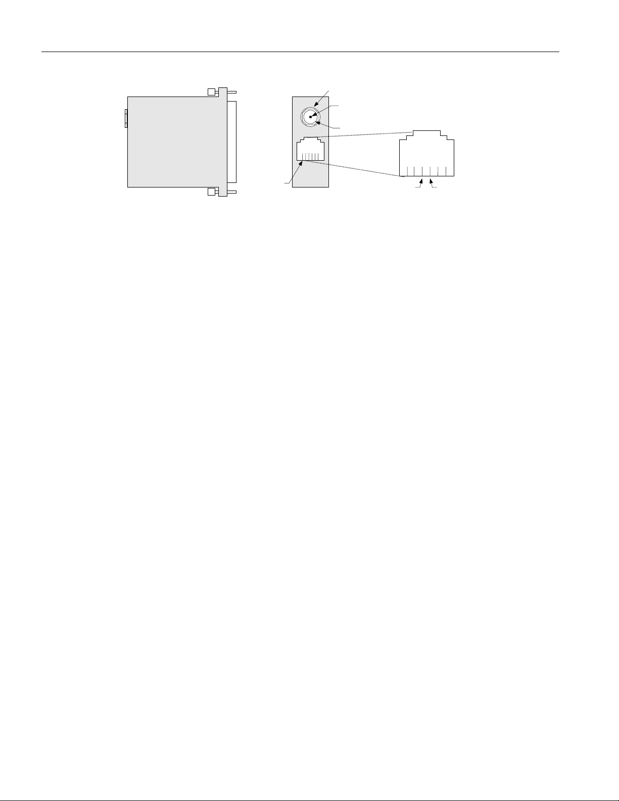
DS9097U-E25 1-WIRE SERIAL PORT ADAPTER AND +12V PINOUTS Figure 2
g
2.1mm Power Jack
- Contact
+ Contact
16234 5
RJ-11
TOP VIEW END VIEW
Return
RJ-11 Pinout
Lookin
into the Socket
1-Wire
12VDC Power for EPROM Programming
Programming EPROMs requires the application of a +12VDC programming pulse. The DS9097U-E25
provides this capability when supplied with +12VDC power. As shown in Figure 2, a 2.1mm power jack is
used to attach either power from a bench supply or common AC wall adapter. Power jack polarity must
be observed: center contact is ground and outer contact is +12V. See EPROM data sheets for voltage
tolerance and current levels required to program devices. The following +12VDC wall adapter has been
successfully used to program devices:
§ Stancor # STA-300R
It can also be purchased from the following:
§ Allied (Stock #928-9895)
§ Newark (Stock #84F2081)
A schematic for a serial port-based adapter similar to the DS9097U-E25 that supports EPROM
programming is shown in Figure 3. This schematic can be used as a reference for developing an adapter
that will operate from an RS232 serial port. If +12V EPROM programming is not a requirement,
components R5-R7, D5, D6, and D9 can be eliminated and the DS2480B VPP signal (pin 5) must be
connected to VDD (pin 4).
2 of 5
Page 3

REFERENCE SCHEMATIC FOR SERIAL PORT 1-WIRE ADAPTER Figure 3
1
14
2
TXD
15
3
RXD
16
4
RTS
17
5
18
6
19
7
GND
20
DTR
21
22
23
24
25
J1
DB25
Femal
D3
BAT54S
1321
U2
VCC
.1uF
C5
ON/OF
GND
VIN
1
2
3
4
1
2
R7
MSMD02
1
GND
1-W
NC
VDD
5
2
1
U1
DS2480B
2
D5
BAT54C
8
RXD
7
TXD
6
POL
5
VPP
12
1
+
C4
10uF
2
16V
1
1
D4
R3
BAT54S
Vcc
1
R1
2.7K
2
Q1
2
2N7002
1
3
3
1
1
R5
R6
3.3K
51
2
2
3
3
D9
D6
9V
bat54c
1
1
4.7K
1
R4
22K
2
Vcc
3
1
Q2
BSS84
2
3
2
4
VCC
13
1
DATA
2
GND
1
C1
.1uF
2
3
1
NC
3
VOU
1
+
C2
10uF
2
16V
MAX1726EUK50 -T
D8
15V
P2
P1
1
GND
2
+12V
D1
BAT54S
1
3
3
D2
BAT54S
2132
2
D7
12V
C3
33uF
+
16V
1
CABLING
A cable is required to apply adapter 1-Wire signals to the parts that are to be programmed or read. The
cable must have a RJ-11 on one end and an appropriate interface to the 1-Wire device or mounting board
on the other. The pinout for the RJ-11 is shown in Figure 2.
Important Note:
When using the DS9097E adapter, the 1-Wire return must be isolated from any other grounds or return
paths. Failure to follow this requirement may damage the DS9097E adapter and possibly the 1-Wire
device.
SOFTWARE REQUIREMENTS
Dallas Semiconductor provides several software utilities for programming 1-Wire devices; these are all
based on installation of the TMEX RunTime Environment (RTE). All Software, including TMEX, is free
of charge and available for download from:
§ http://www.ibutton.com/software/tmex/index.html
An easy to use GUI application called iButton Viewer is automatically installed when the TMEX RTE is
installed. When configured and launched this application provides a display as shown in Figure 4.
3 of 5
Page 4

SCREEN PRINT OF iButton VIEWER OPENING SCREEN Figure 4
As 1-Wire devices are attached to the serial port adapter their 64-bit ROM values are displayed by the
viewer. Double clicking the ROM value launches device read/write utilities. The iButton Viewer supports
two formats for read/write EPROM/EEPROM data: 1-Wire File Structure and raw/user defined. The 1Wire File Structure format, defined in Application Note 114, stores data in a fashion similar to that found
in disk operating systems: directories with files of data. In the 1-Wire File Structure mode, data can be
programmed and read using the iButton Viewer. The raw/user-defined format is unconstrained and data is
written to individual byte locations. Operating in the raw/user-defined mode requires the iButton Viewer
to be set to debug mode. This is set from the menu tool bar by selecting FileàOptionsàDebug Enable.
At the time of this writing the debug mode of the iButton Viewer supports only reading raw EPROM
data. A future update to the iButton Viewer may support raw data programming.
In order to program EPROM devices with a raw data format, the utility TMEPROM.EXE needs to be
used. This program and the source code can be downloaded from the following link:
ftp://ftp.dalsemi.com/pub/auto_id/softdev/tmeprom.zip
4 of 5
Page 5

Before TMEPROM can be run the TMEX-RTE must be installed with a DS9097U-E25 attached during
the installation process of the default 1-Wire port. This ensures that the correct COM Port and adapter
type are configured for TMEPROM operation. The utility will automatically exit if there is no DS9097UE25 and EPROM device attached. When configured and launched with a DS1982/DS2502 attached this
application provides a display as shown in Figure 5.
SCREEN PRINT OF TMEPROM PROGRAM Figure 5
Two additional utilities for EPROM programming are available at the links listed below:
§ Copy hex file into EPROM 1-Wire devices (console, C, 32-bit) 1.03
ftp://ftp.dalsemi.com/pub/auto_id/softdev/eprom103.zip
§ iButton Copy Machine (GUI, Delphi, 32-bit) 3.11Beta9
ftp://ftp.dalsemi.com/pub/auto_id/softdev/ibcm31b9.zip
Using a NVRAM iButton (the DS1992, DS1994, DS1995, or DS1996) and the iButton Viewer, it is
possible to program the raw data into the NVRAM device and then using the iButton Copy Machine to
copy from the NVRAM device to an EPROM device. These programs are not suitable to gang program
EPROM devices. Due to the 12V programming pulse, there must not be any non-EPROM devices on the
line when programming EPROM devices.
SUMMARY
Dallas Semiconductor enables pre-programming of 1-Wire EPROM/EEPROM devices with easy-to-use
serial port adapters and PC-based software. Using one of these low cost adapters and free software
enables the end-user to quickly setup a programming station to configure a device with the data necessary
for prototyping or for easy evaluation of changes to device data sets.
5 of 5
 Loading...