

Page 1
AP-320-MNT-T Ceiling Tile Mount Kit
Installation Guide
Introduction
The AP-320-MNT-T Ceiling Tile Mount Kit allows 320 Series access points to be securely mounted into an
overhead ceiling tile.
Package Contents
Faceplate
Metal bracket
M4-0.7x18 Phillips head screw
M4-0.7x6 Phillips head screw (x2)
M4 hex nuts (x5)
M4 washers (x5)
Support box
Metal eye bolt
Installing the AP-320-MNT-T Ceiling Tile Mount Kit
1. Remove the ceiling tile into which the access point will be installed.
2. Cut a 220mm x 220mm square hole into the center of the ceiling tile. The hole will be wide enough to fit
the screw posts on the faceplate, but does not exceed the diameter of the faceplate.
3. Fit the screw posts of the faceplate into the ceiling tile, so that the screw posts are oriented upward
when the tile is replaced.
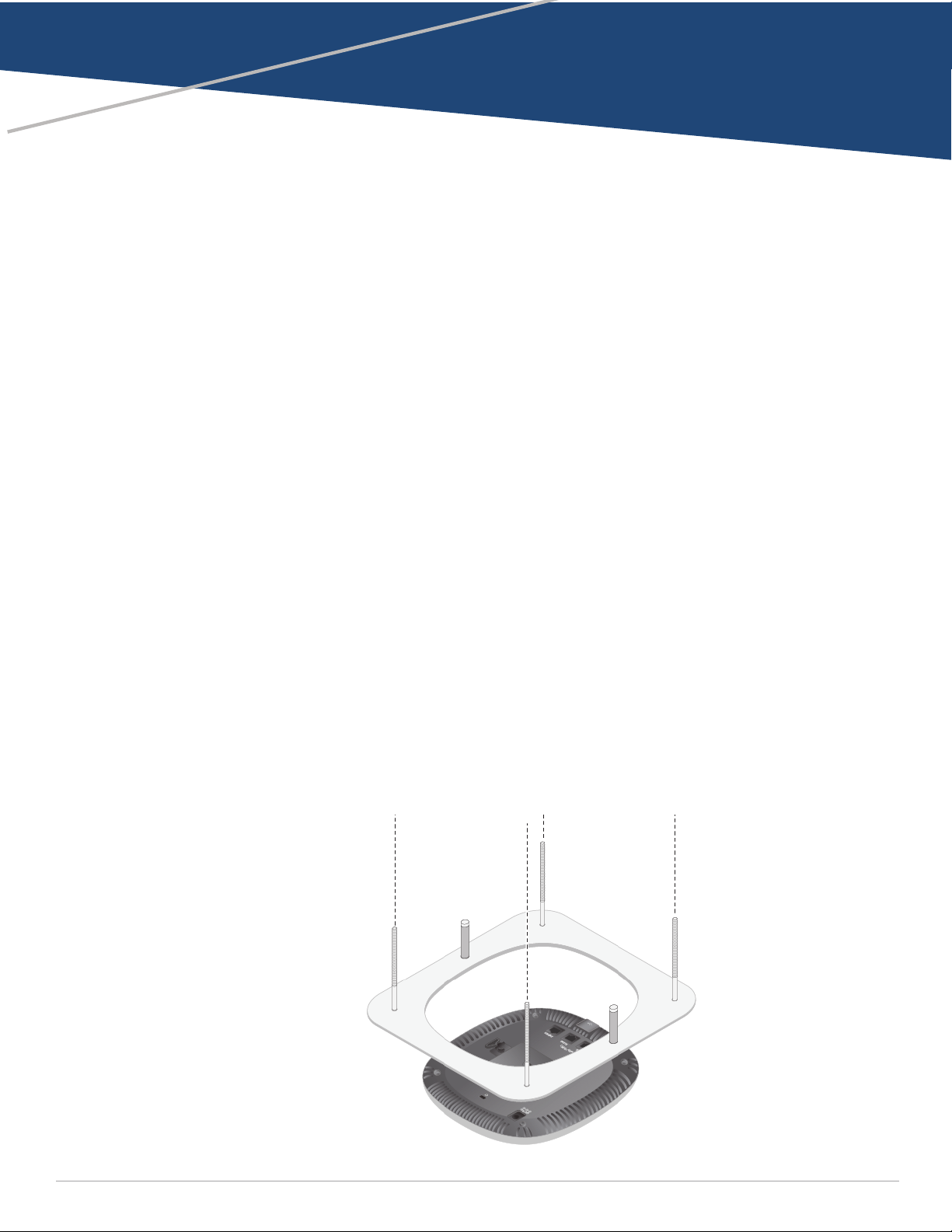
4. Fit the back panel of the access point into the opening on the faceplate until all sides are flat against the
device, as shown in Figure 1.
Figure 1 Fitting faceplate to access point (ceiling tile not shown)
0511837-03 | September 2015 1
Page 2
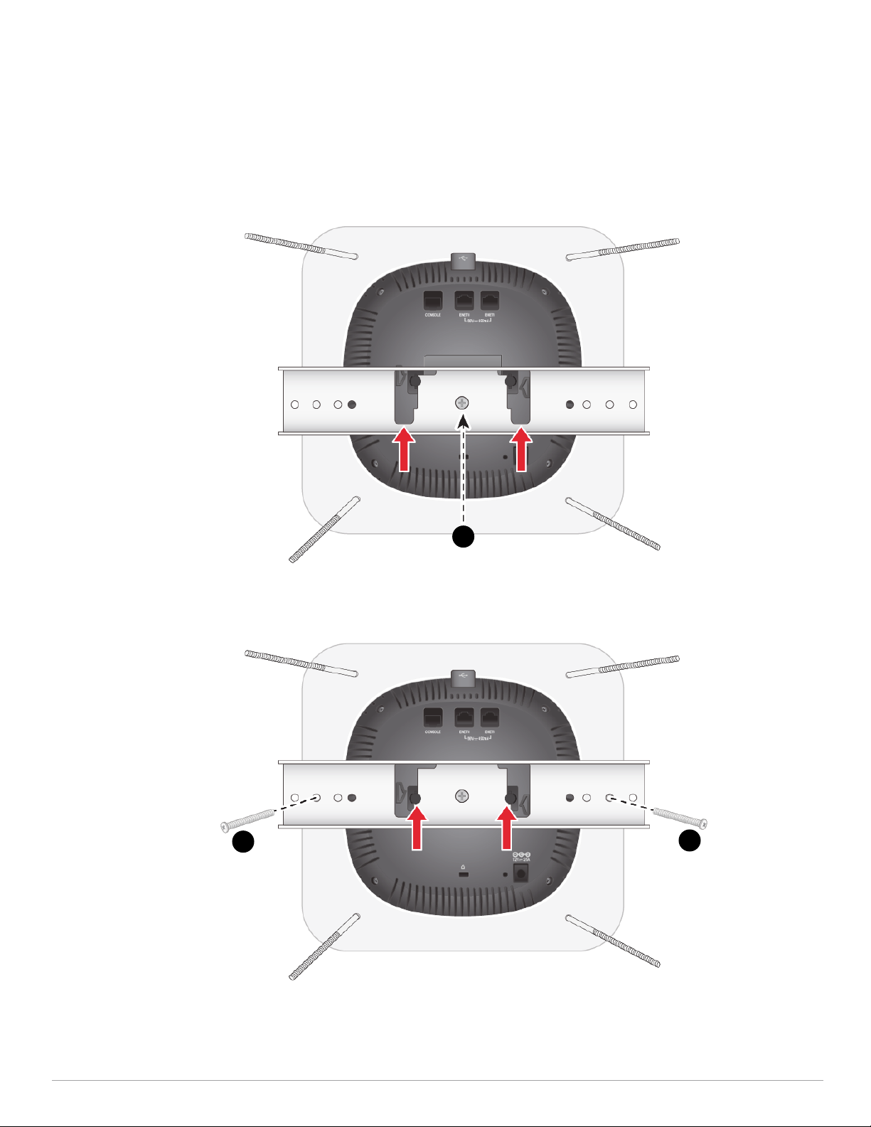
5. Position the metal bracket flat against the back of the access point, as shown in Figure 2. Engage the
bracket by sliding the slots into the pins on the back panel of the access point.
6. Insert the two M4-0.7x6 Phillips head screws (#2) into the holes indicated in Figure 2, and tighten into
the screw posts on the faceplate. Once the two screws are in place, insert the M4-0.7x18 Phillips head
screw (#1) into the center hole and tighten until the access point is fixed into place.
Figure 2 Securing bracket to faceplate
Unlocked position
2
1
Locked position
2
2
7. Install the support box by sliding the screw posts through holes indicated in Figure 3. Use the M4
washers and hex nuts provided to secure the screw posts into the support box. After tightening, check
that the ceiling tile is firmly fixed between the faceplate and support box before continuing to step 8.
2 AP-320-MNT-T Ceiling Tile Mount Kit | Installation Guide
Page 3

Figure 3 Installing faceplate into support box
The ceiling tile shown in Figure 3 is detached from the faceplate for illustrative purposes.
8. For additional stability, screw the metal eye bolt screw into a solid surface above the access point’s
mounted location. Use a metal cable (not included) to secure support box to the eye bolt, leaving
enough slack so that the ceiling tile rests flat against the ceiling grid.
9. Route the power and Ethernet cables to their appropriate ports at the back of the access point, then
replace the ceiling tile to its original position.
3 AP-320-MNT-T Ceiling Tile Mount Kit | Installation Guide
Page 4

4 AP-320-MNT-T Ceiling Tile Mount Kit | Installation Guide
 Loading...