

Dell AP-103H-MNT1 Owner's Manual
Dell Networking W-AP103H Wireless Access Point
System Status LED
Console Port
Pass Through Port
ENET0
DC
Power
Push Button
ENET1
ENET2
Pass Through Port
1000Base-T Gigabit
Ethernet Port
RJ-45 Female
Pin-Out
1
2
3
4
5
6
7
8
Spare Pair
Spare Pair
Spare Pair
Spare Pair
ETH Rx+
ETH RxETH Tx+
ETH Tx-
(POE positive)
(POE positive)
(POE negative)
(POE negative)
(POE negative)
(POE negative)
(POE positive)
(POE positive)
10/100 Mbps Ethernet
ee
nt
Spare Pair
Spare Pair
Spare Pair
Spare Pair
1
ETH Tx+
ETH Tx–
ETH Rx+
ETH Rx–
Installation Guide
The Dell Networking W-AP103H wireless access point supports the IEEE 802.11n
standard for high-performance WLAN. This access point uses MIMO (MultipleInput, Multiple-Output) technology and other high-throughput mode techniques to
deliver high-performance, 802.11n 2.4 GHz or 5 GHz functionality while
simultaneously supporting existing 802.11a/b/g wireless services. The W-AP103H
access point works only in conjunction with a Dell Networking W-Series Mobility
Controller.
The W-AP103H access point provides the following capabilities:
Wireless transceiver
Protocol-independent networking functionality
IEEE 802.11a/b/g/n operation as a wireless access point
IEEE 802.11a/b/g/n operation as a wireless air monitor
Compatibility with IEEE 802.3af PoE
Central management configuration and upgrades through a Dell Controller
Note: The W-AP103H requires Dell Networking W-Series ArubaOS 6.4.1.0 or
later version.
Package Contents
W-AP103H Access Point
Single Gang Wall-box Mounting bracket
2x #6-32 Machine Screws
Security Key
Installation Guide (this document)
Note: Inform your supplier if there are any incorrect, missing, or damaged
parts. If possible, retain the carton, including the original packing materials.
Use these materials to repack and return the unit to the supplier if needed.
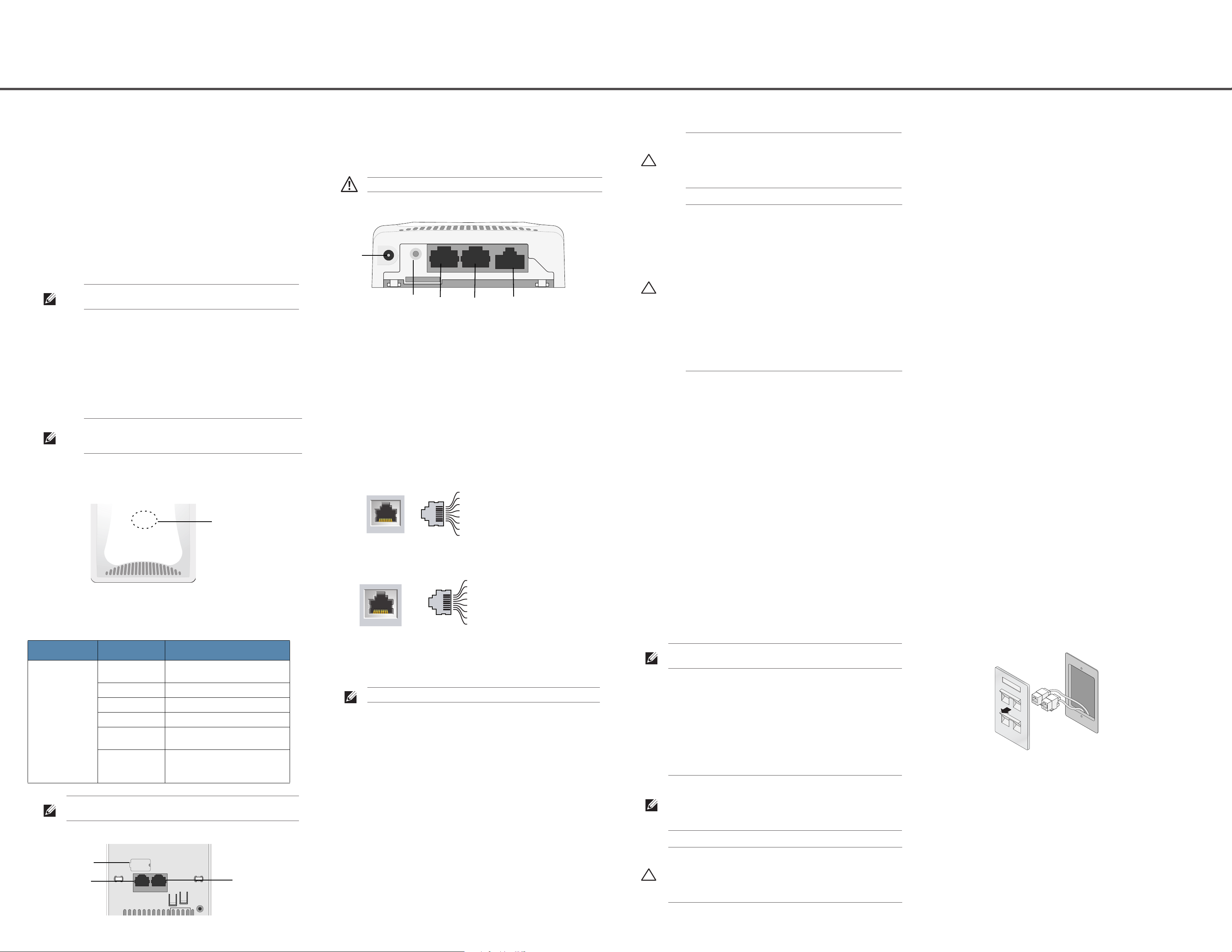
Console Port
The serial console port allows you to connect the AP to a serial terminal or a laptop
for direct local management. This port is a 4-pin connector covered by a dust cover.
An optional serial adapter cable (AP-CBL-SER) is available for use with the WAP103H access point and is sold separately.
Warning: Hot-plug operation is not recommended for the console port.
Figure 3
W-AP103H Bottom View
Ethernet Ports
W-AP103H access point is equipped with a total of three active Ethernet ports
(ENET 0-2). ENET 0 is a 10/100/1000Base-T (RJ-45) auto-sensing, MDI/MDX
wired-network uplink connectivity port. This port supports IEEE 802.3af Power over
Ethernet (PoE), accepting 48VDC (nominal) as a standard defined Powered Device
(PD) from a Power Sourcing Equipment (PSE) such as a PoE midspan injector or
network infrastructure that supports PoE. ENET 1 and 2 are 10/100Base-T (RJ-45)
auto-sensing, MDI/MDX wired-network downlink connectivity ports, used to provide
secure network connectivity to wired devices. ENET 0 is located on the back of the
AP (Figure 2), while ENET 1 and 2 are located on the bottom of the AP (Figure 3).
Additionally, the W-AP103H access point supports a passive pass-through RJ-45
interface to extend a physical connection (typically another Ethernet connection)
from the back of the device to a connector on the bottom.
Before You Begin
Caution: FCC Statement: Improper termination of access points installed in
the United States configured to non-US model controllers will be in
violation of the FCC grant of equipment authorization. Any such willful or
intentional violation may result in a requirement by the FCC for immediate
termination of operation and may be subject to forfeiture (47 CFR 1.80).
Caution: EU Statement:
Lower power radio LAN product operating in 2.4 GHz and 5 GHz bands.
Please refer to the
details on restrictions.
Produit réseau local radio basse puissance operant dans la bande
fréquence 2.4 GHz et 5 GHz. Merci de vous referrer au
W-Series ArubaOS User Guide
Low Power FunkLAN Produkt, das im 2.4 GHz und im 5 GHz Band arbeitet.
Weitere Informationen bezlüglich Einschränkungen finden Sie im
Dell Networking W-Series ArubaOS User Guide
Dell Networking
pour les details des restrictions.
Networking W-Series ArubaOS User Guide.
Apparati Radio LAN a bassa Potenza, operanti a 2.4 GHz e 5 GHz. Fare
riferimento alla
informazioni detagliate sulle restrizioni.
Dell Networking W-Series ArubaOS User Guide
Pre-Installation Network Requirements
After WLAN planning is complete and the appropriate products and their placement
have been determined, the Dell controller(s) must be installed and initial setup
performed before the APs are deployed.
AP Pre-Installation Checklist
Before installing your W-AP103H access point, be sure that you have the following:
for
Dell
per avere
Verifying Pre-Installation Connectivity
Before you install APs in a network environment, make sure that the APs are able to
locate and connect to the controller after power on. Specifically, you must verify the
following conditions:
When connected to the network, each AP is assigned a valid IP address
APs are able to locate the controller
Refer to the Dell Networking W-Series ArubaOS Quick Start Guide for instructions
on locating and connecting to the controller.
Identifying Specific Installation Locations
You can mount the W-AP103H access point on a wall. Use the AP placement map
generated by Dell VisualRF Plan software application to determine the proper
installation location(s). Each location should be as close as possible to the center of
the intended coverage area and should be free from obstructions or obvious sources
of interference. RF absorbers/reflectors/interference sources will impact RF
propagation and should have been accounted for during the planning phase and
adjusted for in VisualRF plan.
Identifying Known RF Absorbers/Reflectors/Interference Sources
Identifying known RF absorbers, reflectors, and interference sources while in the
field during the installation phase is critical. Make sure that these sources are taken
into consideration when you attach an AP to its fixed location.
RF absorbers include:
Cement/concrete—Old concrete has high levels of water dissipation, which dries
out the concrete, allowing for potential RF propagation. New concrete has high
levels of water concentration in the concrete, blocking RF signals.
Natural Items—Fish tanks, water fountains, ponds, and trees
Brick
RF reflectors include:
Hardware Overview
Figure 1
LED
The W-AP103H access point is equipped with one LED that indicates the system
status of the AP.
LED Color/State Meaning
System Status LED Off No power to AP, or LED switched to ‘off
Figure 2
W-AP103H LED on Front
mode’
Red Error condition
Green - Flashing LED switched to ‘blink mode’
Green - Steady AP ready
Amber - Flashing AP booting, or AP in Air or Spectrum
Amber - Steady AP ready, restricted mode:
Note: For more information on blink and off mode of the LED, refer to the
monitor mode
10/100Mbps uplink negotiated
Either radio in non-HT mode
Networking W-Series ArubaOS User Guide.
W-AP103H Ports on Back
Dell
Figure 4
Figure 5
Gigabit Ethernet Port Pin-Out
Fast Ethernet Port Pin-Out
DC Power Socket
The W-AP103H access point has a single 12V DC power jack socket to support
powering through an AC-to-DC power adapter.
Note: If both POE and DC power are available, the AP uses POE.
Push Button
The push button can be used to reset the AP to factory default settings or turn off/on
the System Status LED.
To reset the AP to factory default settings:
1. Power off the AP.
2. Press and hold the push button using a small, narrow object, such as a
paperclip.
3. Power-on the AP without releasing the push button. The system status LED
will flash within 5 seconds.
4. Release the push button.
The system status LED will flash again within 15 seconds indicating that the
reset is completed. The AP will now continue to boot with the factory default
settings.
To turn off/on the system status LED:
During the normal operation of the AP, press the push button using a small,
narrow object, such as a paperclip. The system status LED will be turned off/on
immediately.
Pre-installed wall box
Cat5 UTP cable with network access installed in the wall box
One of the following power sources:
IEEE 802.3af-compliant Power over Ethernet (PoE) source
Dell AP AC-DC adapter kit (sold separately)
Dell Controller provisioned on the network:
Layer 2/3 network connectivity to your access point
One of the following network services:
Aruba Discovery Protocol (ADP)
DNS server with an “A” record
DHCP Server with vendor-specific options
Summary of the Setup Process
Note: It is important that you verify the items listed under AP Pre-Installation
Checklist before you attempt to set up and install a W-AP103H access point.
Successful setup of a W-AP103H access point consists of five tasks, which must be
performed in this order:
1. Verify pre-installation connectivity.
2. Identify the specific installation location for each AP.
3. Install each AP.
4. Verify post-installation connectivity.
5. Configure each AP.
Note: Dell, in compliance with governmental requirements, has designed the
W-AP103H access point so that only authorized network administrators can change
the settings. For more information about AP configuration, refer to the
Networking W-Series ArubaOS Quick Start Guide
ArubaOS User Guide
Caution: Access points are radio transmission devices and as such are subject to
governmental regulation. Network administrators responsible for the
configuration and operation of access points must comply with local broadcast
regulations. Specifically, access points must use channel assignments
appropriate to the location in which the access point will be used.
.
and
Dell Networking W-Series
Dell
Metal Objects—Metal pans between floors, rebar, fire doors, air conditioning/
heating ducts, mesh windows, blinds, chain link fences (depending on aperture
size), refrigerators, racks, shelves, and filing cabinets.
Do not place an AP between two air conditioning/heating ducts. Make sure that
APs are placed below ducts to avoid RF disturbances.
RF interference sources include:
Microwave ovens and other 2.4 or 5 GHz objects (such as cordless phones)
Cordless headset such as those used in call centers or lunch rooms
Installing the AP
The W-AP103H access point is designed to mount into a variety of electrical gang
boxes.
1. Begin by removing the existing data wall plate (if applicable).
Figure 6
2. Remove any existing RJ45 connectors (typically snap-in) or cut/remove the UTP
3. Use a short Ethernet cable (sold separately) to connect the ENET0 port to an
4. Align the mounting holes of the W-AP103H mounting bracket with mounting
Removing Wall Plate (US Single Gang Outlet Box Shown)
cable.
RJ45 connector or crimp an RJ45 plug (not supplied) on the cable and insert in
the ENET0 port. Do the same for the Pass Through port, if used.
holes in the gang box as shown in Figure 7 and Figure 8. For worldwide single
gang outlet box, the mounting bracket provides two sets of mounting holes for
fixing to the box to meet different installation position requirement. See Figure 8
for details.
The applicable standards for the wall boxes are:
IEC 60670-1, GB17466, BS4662 and DIN49073 for Worldwide
ANSI/NEMA OS 1 and OS 2 for US
5. Insert the two included machine screws and tighten them to secure the mounting
Another
two
mounting
holes
bracket.
Note: The included machine screws may not fit all wall boxes.
Figure 7
Figure 8
Bracket to Gang Box (US Single Gang Outlet Box Shown)
Bracket to Gang Box (Worldwide Single Gang Outlet Box Shown)
6. Connect any required cables to the back of the W-AP103H access point.
7. Align the mounting posts on the back of the W-AP103H access point with the
corresponding mounting holes on the mounting bracket as shown in Figure 9.
8. Push the AP against the holes and downward until the posts engage the slots at
the top of the mounting holes. See Figure 9 and Figure 10 for more details.
Figure 9
Figure 10
Fitting W-AP103H to Bracket
Completed Installation
3. If not using PoE, connect the AC-DC power adapter (sold separately) to the DC
power socket located on the bottom of the W-AP103H access point.
Verifying Post-Installation Connectivity
The integrated LED on the AP can be used to verify that the AP is receiving power and
initializing successfully (see Table 1). Refer to the Dell Networking W-Series ArubaOS Quick
Start Guide for further details on verifying post-installation network connectivity.
Configuring the AP
AP Provisioning/Reprovisioning
Provisioning parameters are unique to each AP. These local AP parameters are initially configured on the
controller which are then pushed out to the AP and stored on the AP itself. Dell recommends that
provisioning settings be configured via the ArubaOS Web UI only. Refer to the Dell Networking W-Series
ArubaOS User Guide for complete details.
AP Configuration
Configuration parameters are network or controller specific and are configured and stored on the
controller. Network configuration settings are pushed out to the AP(s) but remain stored on the controller.
Configuration settings can be configured via the Dell Networking W-Series ArubaOS Web UI or CLI. Refer
to Dell Networking W-Series ArubaOS User Guide and/or Dell Networking W-Series ArubaOS CLI Reference
Guide for details.
Product Specifications
Electrical
Ethernet:
1 x 10/100/1000Base-T auto-sensing Ethernet RJ-45 Interface (ENET 0)
2 x 10/100Base-T auto-sensing Ethernet RJ-45 Interfaces (ENET 1 and ENET 2)
1 x passive RJ-45 pass-through interface
MDI/MDX
IEEE 802.3 (10Base-T), IEEE 802.3u (100Base-T). IEEE 802.3ab (1000Base-T)
Power over Ethernet (IEEE 802.3af compliant), 48V DC (nominal) and 56V DC (maximum)/
350mA (see Figure 4 for pin configuration)
Power:
12 VDC power interface, supports powering through an AC-to-DC power adapter
POE support on Ethernet ports: 802.3af-compliant POE sourcing device
Note: If a power adapter other than the one provided by Dell is used in US or
Canada, it should be NRTL Listed, with an output rated 12 VDC, minimum 1.25A,
marked “LPS” and “Class 2”, and suitable for plugging into a standard power
receptacle in US and Canada.
For additional specifications on this product, refer to the product data sheet on dell.com.
Safety and Regulatory Compliance
Note: For country specific restrictions and additional safety and regulatory information, refer
to the multi-language
Information
document included with your Dell controller.
Regulatory Model Names
The regulatory model name of W-AP103H is APINH103.
FCC
This device is electronically labeled. To view the FCC ID:
1. Log into the controller WebUI.
2. Navigate to Maintenance > Controller > About.
Dell Networking W-Series Safety, Environmental, and Regulatory
This equipment has been tested and found to comply with the limits for a Class B digital device, pursuant
to Part 15 of the FCC Rules. This equipment generates, uses and can radiate radio frequency energy and, if
not installed and used in accordance with the manufacturer’s instructions, may cause interference harmful
to radio communications.
If this equipment does cause interference, which can be determined by turning the equipment off and on,
the user is encouraged to try to correct the interference by one or more of the following measures:
Reorient or relocate the receiving antenna.
Increase the separation between the equipment and receiver.
Connect the equipment to an outlet on a circuit different from that to which the receiver is
connected.
Consult the dealer or an experienced radio or TV technician for help.
EU Regulatory Conformance
Dell, hereby declares that the APINH103 device model is in compliance with the essential
requirements and other relevant provisions of Directive 1999/5/EC - CE(!). The
Declaration of Conformity made under Directive 1999/5/EC is available for viewing on dell.com.
EMC Compliance and Warning Statement
This equipment generates, uses and can radiate radio frequency energy, and, if not installed and used in
accordance with the manufacturer’s instructions may cause harmful interference to other devices in the
vicinity. However, there is no guarantee that interference will not occur in a particular installation. If this
equipment causes interference with other devices, which may be determined by turning the equipment off
and on, the user is encouraged to try and correct the interference by one or more of the following measures:
Reorient or relocate the device receiving the interference.
Increase the separation between the equipment.
Connect the equipment into an outlet on a circuit different from that to which the other device(s) are
connected.
Consult the manufacturer or field service technician for help.
The protection against electric shock is Class ll.
Equipment not suitable for use in the presence of flammable mixtures.
Canadian Statement
Under Industry Canada regulations, this radio transmitter may only operate using an antenna of a type and
maximum (or lesser) gain approved for the transmitter by Industry Canada. To reduce potential radio
interference to other users, the antenna type and its gain should be so chosen that the equivalent
isotropically radiated power (e.i.r.p.) is not more than that necessary for successful communication.
This device complies with Industry Canada licence-exempt RSS standard(s).
Operation is subject to the following two conditions: (1) this device may not cause interference, and (2)
this device must accept any interference, including interference that may cause undesired operation of the
device.
Complies with the Class B limits for radio noise emissions as set out in the interference-causing equipment
standard entitled “Digital Apparatus,” ICES-003 of Industry Canada.
Cet apareil numerique de la classe B respecte toutes les exigencies du Reglement sur le materiel brouilleur
du Canada.
Users are advised that high power Radars are allocated as primary users of the bands 5250-5350 MHz and
5650-5850 MHz and these Radars could cause interference and/or damage to Licensed Exempt WLAN
devices.
Proper Disposal of Dell Equipment
For the most current information about Global Environmental Compliance and Dell products, visit
dell.com.
Waste of Electrical and Electronic Equipment
Dell products at end of life are subject to separate collection and treatment in the
EU Member States, Norway, and Switzerland and therefore are marked with the
symbol shown at the left (crossed-out wheelie bin). The treatment applied at end of
life of these products in these countries shall comply with the applicable national
laws of countries implementing Directive 2002/96/EC on Waste of Electrical and
Electronic Equipment (WEEE).
China RoHS
Dell products also comply with China environmental declaration requirements and are
labeled with the “EFUP 25” label shown at the left.
Dell Networking W-AP103H
Wireless Access Point
Installation Guide
Contacting Dell
Web Site Support
Main Website dell.com
Contact Information dell.com /contactdell
Support Website dell.com /support
Documentation Website dell.com /support/manuals
Copyright
© 2014 Aruba Networks, Inc. Aruba Networks trademarks include , Aruba Networks
Aruba Wireless Networks
Management System
All rights reserved. Specifications in this manual are subject to change without notice.
Originated in the USA. All other trademarks are the property of their respective owners.
Open Source Code
Certain Aruba products include Open Source software code developed by third parties, including software code
subject to the GNU General Public License (GPL), GNU Lesser General Public License (LGPL), or other Open
Source Licenses. The Open Source code used can be found at this site:
http://www.arubanetworks.com/open_source
Includes software from Litech Systems Design. The IF-MAP client library copyright 2011 Infoblox, Inc. All rights
reserved. This product includes software developed by Lars Fenneberg, et al.
Legal Notice
The use of Aruba Networks, Inc. switching platforms and software, by all individuals or corporations, to terminate
other vendors’ VPN client devices constitutes complete acceptance of liability by that individual or corporation for
this action and indemnifies, in full, Aruba Networks, Inc. from any and all legal actions that might be taken against
it with respect to infringement of copyright on behalf of those vendors.
®
, the registered Aruba the Mobile Edge Company logo, and Aruba Mobility
®
. Dell™, the DELL™ logo, and PowerConnect™ are trademarks of Dell Inc.
®
,
Removing the AP
1. To remove the W-AP103H access point from the mounting bracket, begin by
inserting the security key into the hole as shown in Figure 11.
2. Use the security key to depress the tab on the AP and push the AP up, releasing
the AP from the mounting holes on the bracket.
Figure 11
Removing W-AP103H
Caution: Dell access points must be installed by a professional installer. The
professional installer is responsible for ensuring that grounding is available and it
meets applicable local and national electrical codes.
Caution: RF Radiation Exposure Statement: This equipment complies with FCC RF
radiation exposure limits. This equipment should be installed and operated with a
minimum distance of 7.87 inches (20cm) between the radiator and your body for
2.4 GHz and 5 GHz operations. This transmitter must not be co-located or
operating in conjunction with any other antenna or transmitter. When operated in
the 5.15 to 5.25 GHz frequency range, this device is restricted to indoor use.
FCC Class B Part 15
This device complies with Part 15 of the Federal Communications Commission (FCC) Rules. Operation is
subject to the following two conditions:
1. This device may not cause harmful interference.
2. This device must accept any interference received, including interference that may cause undesired
operation.
Caution: Changes or modifications to this unit not expressly approved by the party
responsible for compliance could void the user’s authority to operate this
equipment.
European Union RoHS
Aruba Networks Inc., hereby, being the manufacturer of this product, declares
that all CE Marked Dell wireless controller and access points product are
manufactured in accordance to the provisional requirements set forth in the
RoHS Directive 2011/65/EC.
A copy of the Aruba Declaration of Conformity may be obtained upon request from:
Aruba Networks International Ltd.
Building 1000,
Citygate Mahon
Cork Ireland
Please include the regulatory model number located on the product’s regulatory nameplate with the
request.
India RoHS
This product complies with RoHS requirements as prescribed by E-Waste (Management & Handling)
Rules, governed by the Ministry of Environment & Forests, Government of India.
www.dell.com
Dell Networking W-AP103H Wireless Access Point | Installation Guide
Part Number 0511644-01 | July 2014
 Loading...