

Page 1

Dell™ PowerVault™
MD3000i RAID Enclosure
Hardware Owner’s Manual
Page 2

Notes, Notices, and Cautions
NOTE: A NOTE indicates important information that helps you make better use of
your computer.
NOTICE: A NOTICE indicates either potential damage to hardware or loss of data
and tells you how to avoid the problem.
CAUTION: A CAUTION indicates a potential for property damage, personal injury,
or death.
____________________
Information in this document is subject to change without notice.
© 2007 Dell Inc. All rights reserved.
Reproduction in any manner whatsoever without the written permission of Dell Inc. is strictly
forbidden.
Trademarks used in this text: Dell, the DELL logo, PowerEdge, and PowerVault are trademarks of
Dell Inc.; Microsoft, Windows, Windows Server, and MS-DOS are either trademarks or registered
trademarks of Microsoft Corporation in the United States and/or other countries; UNIX is a registered
trademark of The Open Group in the United States and other countries.
Other trademarks and trade names may be used in this document to refer to either the entities claiming
the marks and names or their products. Dell Inc. disclaims any proprietary interest in trademarks and
trade names other than its own.
Model AMP01
June 2007 Rev. A00
Page 3

Contents
1 About Your System . . . . . . . . . . . . . . . . . . 9
Overview . . . . . . . . . . . . . . . . . . . . . . . . . 9
Other Information You May Need . . . . . . . . . . . . 11
Enclosure Features
. . . . . . . . . . . . . . . . . . 9
Modular Disk Storage Manager
. . . . . . . . . . 11
Connection Components
About the Enclosure Connections
Hardware Features
Indicators on the Enclosure Bezel
Front-Panel Indicators and Features
Back-Panel Indicators and Features
RAID Controller Modules
Cache Functions and Features
Power Supply and Cooling Fan Features
. . . . . . . . . . . . . . . . 12
. . . . . . . . . . . 12
. . . . . . . . . . . . . . . . . . . 13
. . . . . . . . . 13
. . . . . . . 14
. . . . . . . 18
. . . . . . . . . . . . . 18
. . . . . . . . . . . 24
. . . . . 24
2 Using Your RAID Enclosure . . . . . . . . . . . 27
Physical Disks, Virtual Disks, and Disk Groups . . . . 27
Physical Disks
Physical Disk States
Self-Monitoring Analysis and Reporting
Technology (SMART)
Virtual Disks and Disk Groups
. . . . . . . . . . . . . . . . . . . 28
. . . . . . . . . . . . . . . . 28
. . . . . . . . . . . . . . . . 29
. . . . . . . . . . . 30
Contents 3
Page 4

Supported RAID Levels . . . . . . . . . . . . . . . . . 31
. . . . . . . . . . . . . . . . . . . . . . . 31
RAID 0
. . . . . . . . . . . . . . . . . . . . . . . 31
RAID 1
. . . . . . . . . . . . . . . . . . . . . . . 32
RAID 5
RAID 10
RAID Level Usage
Segment Size
. . . . . . . . . . . . . . . . . . . . . . . 32
. . . . . . . . . . . . . . . . . 32
. . . . . . . . . . . . . . . . . . . . 33
Hot Spares and Rebuild
Global Hot Spares
Hot Spare Operation
. . . . . . . . . . . . . . . . . . . . . . . 34
Rebuild
. . . . . . . . . . . . . . . . . 33
. . . . . . . . . . . . . . . . . 33
. . . . . . . . . . . . . . . . 33
Media Errors and Unreadable Sectors . . . . . . . . . 34
RAID Operations and Features
Virtual Disk Operations
Disk Group Operations
RAID Background Operations Priority
Virtual Disk Migration and Disk Roaming
Advanced Features
. . . . . . . . . . . . . . . . . . . 42
Storage Partitions
Host Types
. . . . . . . . . . . . . . . . . . . . . 44
Snapshot Virtual Disks
Snapshot Repository Virtual Disk
Virtual Disk Service
Volume Shadow-Copy Service
Virtual Disk Copy
Using Snapshot and Disk Copy Together
. . . . . . . . . . . . . 35
. . . . . . . . . . . . . . . 35
. . . . . . . . . . . . . . . 37
. . . . . . . 39
. . . . . 40
. . . . . . . . . . . . . . . . . 42
. . . . . . . . . . . . . . . 44
. . . . . . . . . 45
. . . . . . . . . . . . . . . . . 46
. . . . . . . . . . . 46
. . . . . . . . . . . . . . . . . . 47
. . . . . . 48
4 Contents
Hardware Redundancy and Failover
Redundancy and Non-Redundancy
Multi-Path Software
. . . . . . . . . . . . . . . . 49
. . . . . . . . . . 48
. . . . . . . . 49
Page 5

When a RAID Controller Module Is Replaced
or Removed
RAID Controller Failover Modes
. . . . . . . . . . . . . . . . . . . . . 50
. . . . . . . . . . 51
Thermal Shutdown
Updating Enclosure Firmware
RAID Controller Module Firmware
Physical Disk Firmware
Expansion Enclosure Firmware
Best Practices and Recommendations
. . . . . . . . . . . . . . . . . . . 52
. . . . . . . . . . . . . 52
. . . . . . . . . 52
. . . . . . . . . . . . . . 53
. . . . . . . . . . 53
. . . . . . . . . 54
3 Installing Enclosure Components . . . . . . 55
Recommended Tools . . . . . . . . . . . . . . . . . . 55
Removing and Replacing the Front Bezel
Removing and Installing Physical Disks
Removing Physical Disks from the Enclosure
Installing SAS Physical Disks in the
Enclosure
. . . . . . . . . . . . . . . . . . . . . . 58
Removing and Installing a RAID Controller
Module
. . . . . . . . . . . . . . . . . . . . . . . . . . 60
Removing a RAID Controller Module
Installing a RAID Controller Module
. . . . . . . . 55
. . . . . . . . 56
. . . 57
. . . . . . . 60
. . . . . . . . 61
Removing and Installing a RAID Controller
Module Backup Battery Unit
. . . . . . . . . . . . . . 62
Removing and Installing the Power Supply/Cooling
Fan Module
. . . . . . . . . . . . . . . . . . . . . . . 64
Removing a Power Supply/Cooling
Fan Module
. . . . . . . . . . . . . . . . . . . . . 64
Installing a Power Supply/Cooling
Fan Module
. . . . . . . . . . . . . . . . . . . . . 65
Contents 5
Page 6

Removing and Installing the Control Panel . . . . . . . 66
Removing the Control Panel
Installing the Control Panel
. . . . . . . . . . . . 66
. . . . . . . . . . . . 67
Removing and Installing the Midplane
. . . . . . . . . 68
4 Troubleshooting Your Enclosure . . . . . . . 71
Safety First—For You and Your Enclosure . . . . . . . 71
Start-Up Routine
Troubleshooting External Connections
Troubleshooting a Wet Enclosure
Troubleshooting a Damaged Enclosure
Troubleshooting Power Supplies
Troubleshooting Enclosure Cooling Problems
Troubleshooting a Fan
Troubleshooting SAS Physical Disks
Troubleshooting Enclosure Connections
Hard Controller Failures and Lockdown
Conditions
Invalid Enclosure
ECC Errors
PCI Errors
Critical Conditions
Noncritical Conditions
. . . . . . . . . . . . . . . . . . . . . 71
. . . . . . . . . 72
. . . . . . . . . . . . 72
. . . . . . . . . 73
. . . . . . . . . . . . 73
. . . . . 75
. . . . . . . . . . . . . . . 75
. . . . . . . . . . 76
. . . . . . . . 77
. . . . . . . . . . . . . . . . . . . . . . . . 78
. . . . . . . . . . . . . . . . . . 78
. . . . . . . . . . . . . . . . . . . . . 78
. . . . . . . . . . . . . . . . . . . . . . 79
. . . . . . . . . . . . . . . . . 79
. . . . . . . . . . . . . . . 79
6 Contents
Page 7

5 Getting Help . . . . . . . . . . . . . . . . . . . . . . 81
Obtaining Assistance . . . . . . . . . . . . . . . . . . 81
Technical Support and Customer Service
Online Services
. . . . . . . . . . . . . . . . . . 82
Automated Order-Status Service
. . . . . 82
. . . . . . . . . 83
Dell Enterprise Training
Problems With Your Order
Product Information
Returning Items for Warranty Repair or Credit
Before You Call
Contacting Dell
. . . . . . . . . . . . . . . . . 83
. . . . . . . . . . . . . . . 83
. . . . . . . . . . . . . . . . . . . 83
. . . . . 83
. . . . . . . . . . . . . . . . . . . . . 84
. . . . . . . . . . . . . . . . . . . . . 84
Glossary . . . . . . . . . . . . . . . . . . . . . . . . . . . . . 87
Contents 7
Page 8

8 Contents
Page 9

About Your System
The Dell™ PowerVault™ MD3000i is a 3U rack-mounted external Redundant
Array of Independent Disks (RAID) storage array capable of accommodating
up to 15 3.0-Gbps, Serial-Attached SCSI (SAS) disks. The RAID enclosure
can be daisy-chained with up to two additional MD1000 expansion
enclosures, providing access to a maximum of 45 disks in the entire storage
array. Connectivity between the RAID enclosure and the host server is
provided by a standard Ethernet connection, and communication between
the two is established through an iSCSI initiator.
Overview
The RAID enclosure is designed for high availability, offering redundant
access to data storage. It features support for both single RAID controller
configuration and dual RAID controller configuration. For each
configuration, up to 16 hosts can be connected through industry-standard
1-Gb network interface cards (NICs).
The MD3000i storage array provides dual active/active RAID controller
modules, redundant power supplies, and redundant fans. The RAID
enclosure is designed for high-performance environments: eight-node clusters
or multi-host storage access for up to 16 host servers.
Storage management can be either in-band through the iSCSI connection, or
out-of-band using an Ethernet connection to the Management Port on the
RAID controller modules.
Enclosure Features
Features include:
• Support for up to 16 Microsoft Windows® or Linux host servers
• 3U chassis for rack mounting
• RAID controller modules in two supported configurations:
– Single-controller configurations
– Dual-controller configurations for high availability
About Your System 9
Page 10

• Two redundant, hot-pluggable power supply/fan modules
• 512 MB of mirrored cache on each RAID controller module
• Battery backup unit in each RAID controller module that protects against
cache data loss for up to 72 hours
• Support for up to 45 3.5" SAS physical disks
• Support for up to 255 virtual disks per disk group
• Up to 2 TB (2036 GB) storage on a single virtual disk
• Support for up to two PowerVault MD1000 expansion enclosures through
SAS Out port connectors on the RAID controller modules
• Online firmware updates (without taking the enclosure offline) for the
following components:
– RAID controller modules
–NVSRAM
– Physical disk
NOTE: Dell recommends stopping all I/O to the array when downloading
physical disk firmware.
– Expansion enclosure management modules (EMMs)
• Task-based configuration software (MD Storage Manager)
• Optional snapshot virtual disk (premium feature), up to four snapshots per
virtual disk and 128 snapshots per array
• Optional virtual disk copy (premium feature), up to 255 virtual disk copies
per array
• Continuous background event monitoring for critical problems, such as
impending physical disk failure or failed RAID controller modules
• Host-based, multipath failover software for redundant configurations to
automatically reroute I/O activity from a failed, offline, or removed RAID
controller module to its alternate RAID controller module (or from a failed
iSCSI connection). This capability maintains a data path between the host
server and the
storage array.
10 About Your System
Page 11
Modular Disk Storage Manager
The Modular Disk (MD) Storage Manager software is a graphic interface with
wizard-guided tools and a task-based management structure designed to
reduce the complexity of installation, configuration, management, and
diagnostic tasks. MD Storage Manager can be used on any host server
attached to the storage array, as well as on storage management stations
connected to the same subnetwork as the RAID enclosure, to create and
manage multiple storage arrays.
NOTE: The MD Storage Manager uses TCP/UDP port 2463 for discovery and
management of the MD3000i storage array.
For more information, see the MD Storage Manager User's Guide.
Other Information You May Need
CAUTION: The Product Information Guide provides important safety and
regulatory information. Warranty information may be included within this
document or as a separate document.
• The
•
•
• The
• The
• The Dell PowerVault MD3000i
• Dell PowerVault MD1000 Documentation is available at
• Dell PowerEdge Cluster Documentation is available at
Rack Installation Guide
with your rack solution describes how to install your
Getting Started With Your System
features, setting up your
Setting Up Your PowerVault MD3000i
and cabling your storage array.
PowerVault MD3000i Installation Guide
configuration instructions for both software and hardware.
PowerVault MD Storage Manager CLI Guide
about using the command line interface (CLI).
configuration and management tools, as well as the full documentation
set.
for users who incorporate MD1000 expansion enclosures.
A link to clustering documentation is also included on the
under
Product Documentation
or
Rack Installation Instructions
provides an overview of
enclosure
, and technical specifications.
provides an overview of setting up
provides installation and
Resource CD
.
provides documentation for
included
enclosure
provides information
into a rack.
enclosure
support.dell.com
support.dell.com
Resource CD
.
About Your System 11
Page 12

• Updates are sometimes included to describe changes to the
software, and/or documentation.
NOTE: Always check for updates on support.dell.com and read the updates
first because they often supersede information in other documents.
• Release notes or readme files are included to provide last-minute updates
to the
enclosure
material intended for experienced users or technicians.
or documentation or advanced technical reference
enclosure
,
Connection Components
Before connecting your RAID enclosure, ensure that the following are
available:
• The components that shipped with your RAID
– Power cords (2)
– MD3000i Resource CD
– Setting Up Your PowerVault MD3000i
– Rail kit
• Any relevant documentation, including:
– Getting Started With Your System
–
Rack Installation Guide
–
Product Information Guide
warranty information)
– Readme files
• #2 Phillips screwdriver
or
Rack Installation Instructions
(for important safety, regulatory, and
enclosure
, including:
About the Enclosure Connections
The RAID enclosure is connected to a host server via two RAID controller
modules. The RAID controller modules are identified as RAID controller
module 0 and RAID controller module 1 (see Figure 1-4).
Each RAID controller module has two iSCSI In port connectors that provide
connection to the host server. The iSCSI In port connectors are labeled 0
and 1.
12 About Your System
Page 13
Each MD3000i RAID controller module also contains a SAS Out port
connector. This port allows you the option to connect the RAID enclosure to
an expansion enclosure.
Refer to the
examples of how to configure your storage array.
PowerVault MD3000i Installation Guide
for details and illustrated
Hardware Features
The remainder of this section describes the hardware features available on the
RAID enclosure, including:
• Indicators on the enclosure bezel
• Front-panel and back-panel indicators and features
• Redundant power supply and cooling fan modules
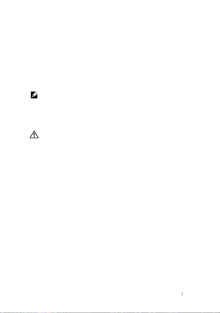
Indicators on the Enclosure Bezel
An optional locking bezel can be installed on the front of the enclosure to
limit access.
Table 1-1 lists conditions indicated by the lights on the bezel.
on installing and removing the bezel, see "Removing and Replacing the Front
Bezel" on page 55.
Figure 1-1. LEDs on the Front Bezel
Figure 1-1 illustrates the indicators and components on the bezel.
For information
1
2
3
About Your System 13
Page 14
Table 1-1. Front-Bezel Indicators
Item LED Indicator LED Icon Condition
1 Split mode (green) Because this mode is unused in the system,
this LED should always be unlit.
NOTE: This LED comes on if the enclosure
mode switch on the enclosure’s front panel is
in the split mode position before the
enclosure is turned on.
2 Power (green) When lit, at least one power supply is
supplying power to the enclosure.
3 Enclosure status
(blue/amber)
Steady amber: Power is on and enclosure is
in reset state.
Steady blue: Power is on and enclosure
status is OK.
Flashing blue: Enclosure LED is being
blinked by MD Storage Manager.
Flashing amber: Enclosure is in fault state.
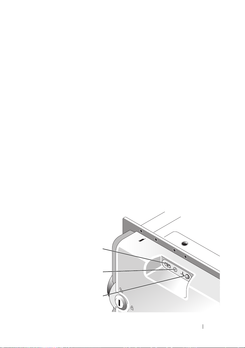
Front-Panel Indicators and Features
Figure 1-2 shows the LED indicators and components on the enclosure’s
front panel (optional locking bezel not shown). Table 1-2 lists the conditions
and functions indicated by each.
14 About Your System
Page 15
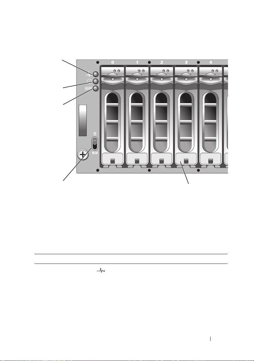
Figure 1-2. Front-Panel Features
1
2
3
4
1 enclosure status
LED
4 enclosure mode
switch
Table 1-2. Front-Panel Components
Component Icon Condition
Enclosure status LED
(blue/amber)
2 power LED 3 split mode LED (not
5 physical disks (15)
Steady amber: Power is on and enclosure is in
reset state.
Steady blue: Power is on and enclosure status
is OK.
Flashing blue: Enclosure LED is being blinked
by MD Storage Manager.
Flashing amber: Enclosure is in fault state.
5
used)
About Your System 15
Page 16
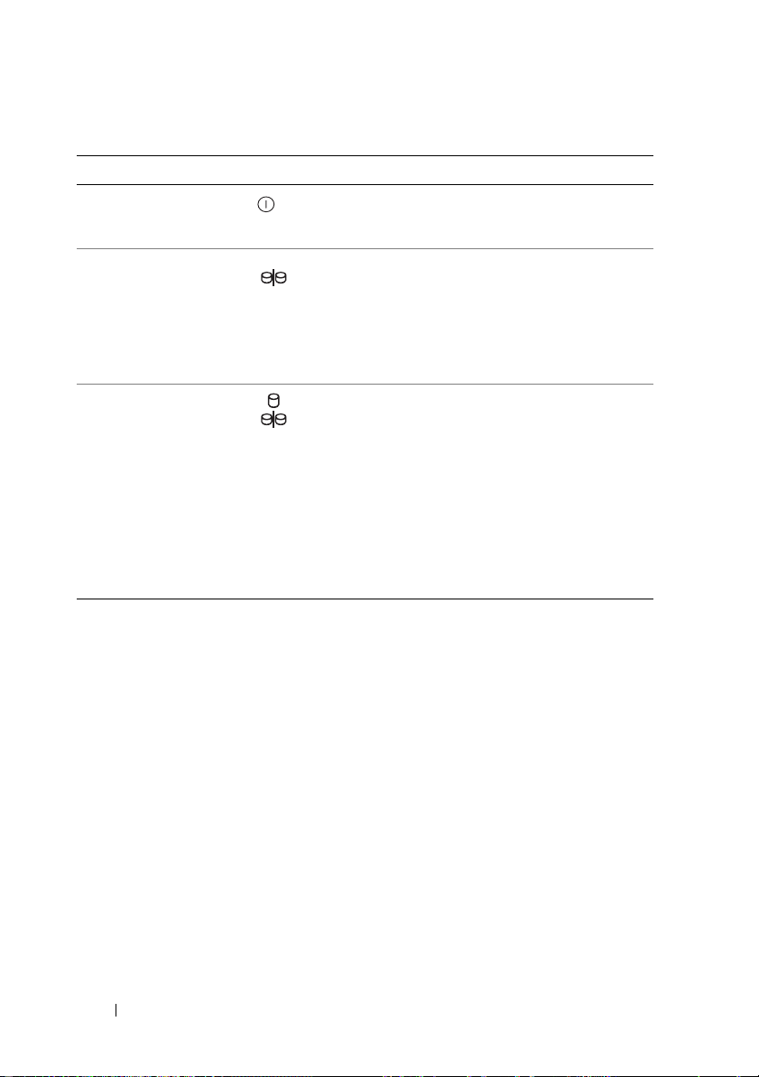
Table 1-2. Front-Panel Components (continued)
Component Icon Condition
Power LED (green) When lit, at least one power supply is
supplying power to the enclosure.
Split mode LED (green) Because this mode is unused in the system, this
LED should always be unlit.
NOTE: This LED comes on if the enclosure mode
switch on the enclosure’s front panel is in the
split mode position before the enclosure is
turned on.
Enclosure mode switch The function of this switch is not applicable to
your MD3000i. However, if additional MD1000
expansion enclosures are daisy chained to your
system, the enclosure mode switch on those
enclosures must be in unified-mode position.
NOTE: This switch must be set prior to turning
on the system. Changing the switch setting after
the system is turned on will have no effect on
enclosure configuration until the system goes
through a complete power cycle.
Physical Disk Carrier LED Indicators
Each physical disk carrier in your enclosure has two LEDs: an activity LED
(green) and a bicolor (green/amber) status LED (see Figure 1-3). The activity
LED flashes whenever the physical disk is accessed. Table 1-3 lists the flash
patterns for the status LED.
16 About Your System
Page 17
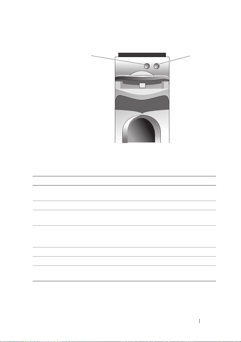
Figure 1-3. Physical Disk Carrier LED Indicators
1
1 activity LED 2 status LED
Table 1-3. Physical Disk Carrier Status LEDs
Status LED Description
Off Physical disk not yet discovered by host server or an
unsupported disk is present
Steady green Physical disk is online
Green flashing (250 milliseconds
[ms])
Green flashing
On 400 ms
Off 100 ms
Amber flashing (125 ms) Physical disk failed
Flashing green, amber, and off Physical disk failure predicted (SMART)
Green 3 seconds, amber
3 seconds, and off 3 seconds
Physical disk is being identified
Physical disk rebuilding
Physical disk rebuild aborted
2
About Your System 17
Page 18
Back-Panel Indicators and Features
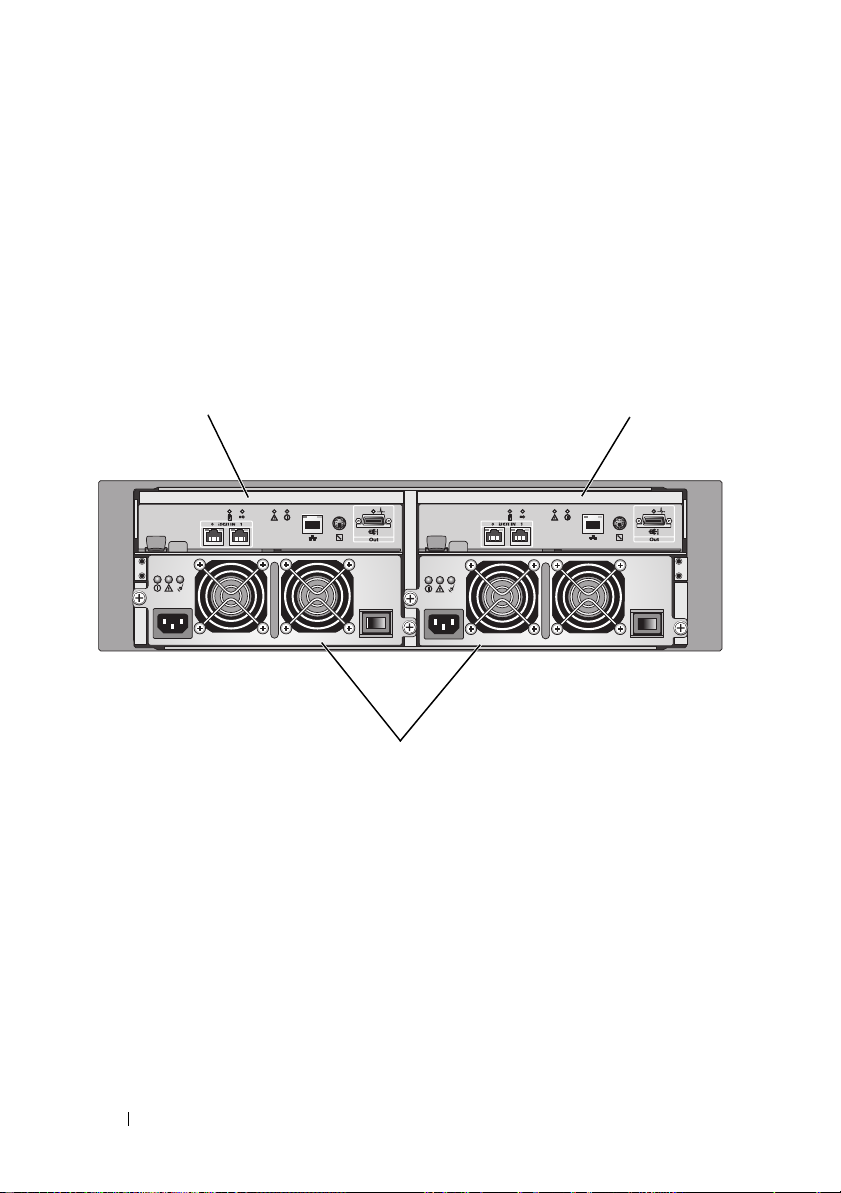
Figure 1-4 shows the back-panel features of the enclosure. A fully populated
enclosure with dual RAID controllers and two power supply/cooling fan
modules is shown. However, a single RAID controller module is supported,
and the enclosure can run temporarily on one power supply/cooling fan
module. For more information, see "Power Supply and Cooling Fan Features"
on page 24.
Figure 1-4. Back-Panel Features
1 2
3
1 RAID controller
module 0
2 RAID controller
module 1
3 power supply/cooling
fan modules (2)
RAID Controller Modules
The RAID controller modules provide high-performance, advanced virtual
disk configuration, and fault-tolerant disk subsystem management. Each
RAID controller module contains 512 MB of cache that is mirrored with the
other controller's cache for high availability and protected by a battery for up
to 72 hours.
18 About Your System
Page 19

Each RAID controller module provides data path and enclosure management
functions for your enclosure, including:
• Monitoring and controlling enclosure environment elements
(temperature, fans, power supplies, and enclosure LEDs)
• Controlling access to the
• Communicating
enclosure
physical disk
s
attributes and states to the host server
Each RAID controller module has dual iSCSI In ports for host access. The
two iSCSI ports provide redundant host connections and support a high
availability storage environment. Various configurations can be utilized, in
both
single controller
and
dual controller
mode, to connect the storage
enclosure to hosts depending on specific redundancy needs. For example:
•
Single Path Data Configuration
– The single path provides a large
number of nonredundant physical connections to the array through an
industry-standard Gigabit Ethernet Switch.
•
Redundant Dual Path (RDP) Data Configuration
– The RDP allows two
separate physical paths for each client through a Gigabit Ethernet Switch.
In addition, this configuration provides full redundancy through the use of
either redundant disk array controller (RDAC) drivers or multipathing I/O
(MPIO) drivers.
For detailed information on cabling, see the
.
Guide
PowerVault MD3000i Installation
RAID Controller Module Connectors and Features
Figure 1-5 shows a single
of the enclosure.
RAID controller module
RAID controller module
connectors and components shown
include:
• Two iSCSI In port connectors
• Management port Ethernet connector
NOTE: The RAID controller module network configuration can be assigned
using a DHCP server (the default setting). If a DHCP server is not available
(time-out is 10 seconds) then the RAID controller modules uses the static IP
addresses of 192.168.128.101 for controller 0 and 192.168.128.102 for
controller 1.
as it appears from the rear
About Your System 19
Page 20
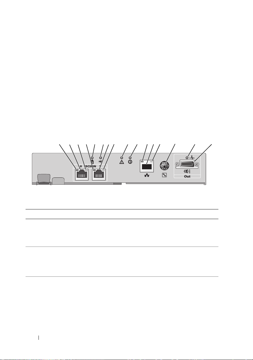
• Eleven LEDs (two iSCSI In link speed/activity, two iSCSI In link duplex
mode, two Ethernet link/speed, battery fault, SAS link fault/connectivity,
cache active, controller fault, and controller power)
• One SAS Out port connector
• Debug port
For a description of each component on the front panel of the RAID
controller module, see Table 1-4. For an explanation of how to connect the
enclosure using the
MD3000i Installation Guide
Figure 1-5. RAID Controller Module External Panel (front view)
1 68 9 10 11 13 15 1612 1442 3 5 7
Table 1-4. RAID Controller Module Component Functions
Item Component Icon Function
1 iSCSI In Port 0 Link
Speed/Activity
Status LED
2 iSCSI In Port 0 In-0 Provide host-to-controller iSCSI
3 iSCSI In Port 0 Link
Duplex Mode
RAID controller module
.
Green: Link is operating at 1000 Mbps.
Amber: Link is operating at 100 Mbps.
Off: iSCSI connection is not active.
connection. If LED is solid, there is no
activity on the link. If the LED is blinking,
there is activity on the link.
Green: Full-duplex mode.
Off: Half-duplex mode.
ports, see the
PowerVault
NOTE: Half-duplex mode is supported only if
the link speed is 100Mbps.
20 About Your System
Page 21

Table 1-4. RAID Controller Module Component Functions (continued)
Item Component Icon Function
4 iSCSI In Port 1 Link
Speed/Activity
Status LED
5 Battery Fault LED
(amber)
6 Cache Active LED
(green)
7 iSCSI In Port 1 In-1 Provide host-to-controller iSCSI
8 iSCSI In Port 1 Link
Duplex Mode
Green: Link is operating at 1000 Mbps.
Amber: Link is operating at 100 Mbps.
Off: iSCSI connection is not active.
Amber: Battery backup unit or battery has
failed or is missing.
Off: Battery backup unit and battery is
operating normally.
Green: On-board controller memory
contains data.
Off: On-board controller memory is empty.
connection. If LED is solid, there is no
activity on the link. If the LED is blinking,
there is activity on the link.
Green: Full-duplex mode.
Off: Half-duplex mode.
NOTE: Half-duplex mode is supported only if
the link speed is 100Mbps.
9 Controller Fault
LED (amber)
Amber: Controller fault detected.
Off: Controller is operating normally.
10 Controller Power
LED (green)
11 Ethernet Link LED
(green)
12 Management Port
Ethernet Connector
Green: Controller power is on.
Off: Controller is not powered.
Green: Ethernet connection is active.
Off: Ethernet connection is not active.
Provide a 10/100 Mbps Ethernet
connection for out-of-band management of
the enclosure.
About Your System 21
Page 22
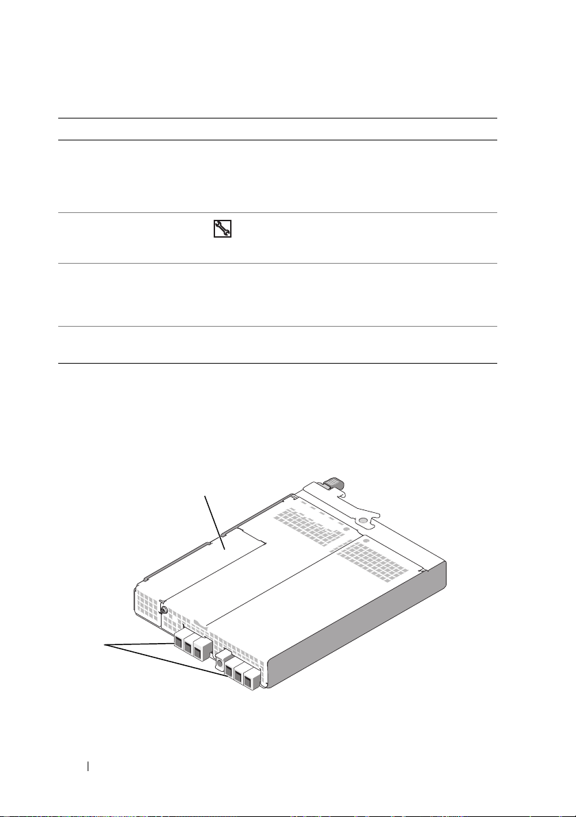
Table 1-4. RAID Controller Module Component Functions (continued)
Item Component Icon Function
13 Ethernet Speed
LED (green)
14 Debug Port Dell support only.
Green: Ethernet connection is operating at
100 Mbps.
Off: Ethernet connection is operating at
10 Mbps or is not active.
15 SAS Link Fault
LED
16 SAS Out Port Out Provides SAS connection for cabling to a
The
RAID controller module
connects to the enclosure midplane via the two
Amber: Between 1–3 links are connected.
Green: All four links are connected.
Off: All links are down.
downchain expansion enclosure.
midplane connectors on its internal (rear) panel. The RAID controller
module is shown in Figure 1-6.
Figure 1-6. RAID Controller Module
1
2
1 battery cover 2 midplane connectors (2)
22 About Your System
Page 23

Battery Backup Unit
Each RAID controller contains a three-cell lithium-ion battery backup unit
(BBU) that powers the controller’s cache memory and preserves the cache
contents in the event of a power outage of up to 72 hours. The RAID
controller firmware performs a test of the BBU at startup and will illuminate
the battery fault LED if the battery is not operating within specified ranges,
or if the battery is missing. The battery begins recharging automatically if the
test determines that it is necessary. For a description of the battery fault LED,
see Table 1-4. For information on removing and installing the BBU, see
"Removing and Installing a RAID Controller Module Backup Battery Unit"
on page 62.
NOTE: For virtual disks, the RAID controller firmware changes the data cache
setting based on the state of the battery. If the battery is missing or does not have
sufficient charge, the controller flushes the cache and sets the write cache
attribute to Write Through for all virtual disks. When the battery is replaced, Write
Back is reenabled.
The RAID controller module logs the age of the battery and issues a
replacement reminder message approximately six weeks before expiration.
After replacing the battery, you must use MD Storage Manager to reset the
battery age.
RAID Enclosure Thermal Shutdown
Enclosure management provides a feature that automatically shuts down the
enclosure when the temperature within the storage enclosure exceeds a safe
threshold. Thermal shutdown protects the data on the physical disks from
corruption in the event of cooling system failure. Because the battery backup
unit
protects against cache data loss for up to 72 hours,
all data in the cache is
saved. It is not necessary to shut down any expansion enclosures attached to
the storage enclosure.
Temperature threshold values are used to determine the temperature at
which shutdown occurs. These thresholds are default settings and cannot be
changed. If the temperature sensors on the backplane detect a temperature
exceeding the Nominal Failure Threshold, a critical event is set. If the
Maximum Failure Threshold is reached, shutdown of the enclosure power
supplies occurs within 3 minutes. A third threshold, the Shutdown Threshold,
shuts down the enclosure power supplies within 5 seconds after it is reached.
About Your System 23
Page 24

Cache Functions and Features
Cache Mirroring
The cache mirroring function copies accepted host-write data from the
primary controller to the partner controller. This action ensures that hostwrite data is safely mirrored to the partner controller before successful
completion status is returned to the host. If a controller fails, the surviving
controller safely retains all mirrored data. Cache mirroring is enabled by
default.
Write-Back Cache
Write-back cache is a caching strategy whereby write operations result in a
completion signal being sent to the host operating system as soon as the
cache receives the data to be written. The target physical disk will receive the
data at a more appropriate time in order to increase controller performance.
In dual-active controller configurations with write-back caching enabled, the
write data is always copied to the cache of the second controller before
completion status is issued to the host initiator. Write Back is enabled by
default.
Write-Through Cache
Write-through cache is a caching strategy whereby data is written to the
physical disk before completion status is returned to the host operating
system. Write-through cache is considered more secure than write-back
cache, since a power failure is less likely to cause loss of data. The RAID
controller automatically switches to write-through if cache mirroring is
disabled or if the battery is missing or has a fault condition.
NOTE: Write cache settings are not user-configurable.
Power Supply and Cooling Fan Features
Your RAID enclosure supports two integrated, hot-pluggable power
supply/cooling fan modules. Both modules must be installed to ensure proper
cooling. Each module contains two separate cooling fans. The enclosure
requires at least three of the cooling fans to operate to avoid overheating.
24 About Your System
Page 25
CAUTION: A power supply/cooling fan module can be removed from a powered-
on enclosure for a maximum period of no more than 5 minutes. Beyond that time,
the enclosure may automatically shut down to prevent damage to the enclosure
and/or enclosure components.
A power supply/cooling fan module can be replaced without powering down
the enclosure. For information on removing and replacing the modules, see
"Removing and Installing the Power Supply/Cooling Fan Module" on page 64.
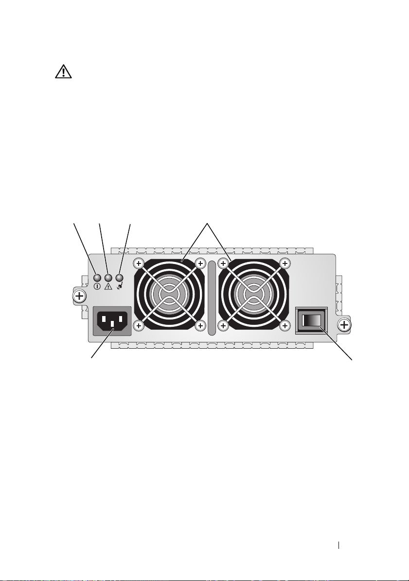
Figure 1-7 shows the power supply/cooling fan module features and LED
indicators. Table 1-5 lists the LED indicator descriptions.
Figure 1-7. Power Supply and Cooling Fan Module LED Features and Indicators
14
2 3
6
1 DC power LED 2 Power supply/cooling fan
fault LED
4 cooling fans (2) 5 on/off switch 6 AC power connector
3AC power LED
About Your System 25
5
Page 26
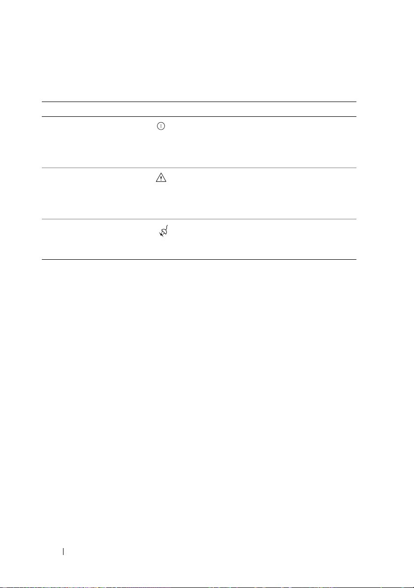
Table 1-5. Power Supply/Cooling Fan Module LED Indicators
Type Color Icon Function
DC power Green On: DC output voltages are within
specifications.
Off: No power or voltages not within
specifications.
Power
supply/cooling
fan fault
AC power Green On: AC input voltage is within specifications.
Amber On: DC output voltages are not within
specifications or one (or both) fans are in fault.
Off: No fault condition is present.
Off: No power or voltages not within
specifications.
26 About Your System
Page 27

Using Your RAID Enclosure
This section covers the following information:
• Basic concepts of a RAID solution including physical disks, virtual disks,
and disk groups
• RAID levels supported by MD Storage Manager
• Hot spare operations and rebuilds
• Media errors and unreadable sectors
• RAID operations and features
• Advanced RAID features
• Hardware redundancy and failover including cabling
• Updating enclosure firmware
• Best practice recommendations
Physical Disks, Virtual Disks, and Disk Groups
Physical disks in your RAID array provide the physical storage capacity for
your data. Before you can begin writing data to the storage array, you must
configure the physical storage capacity into logical components, called disk
groups and virtual disks.
A disk group is a set of physical disks upon which multiple virtual disks are
created. The maximum number of physical disks supported in a disk group
is 30. You create disk groups from unconfigured capacity on your storage array.
A virtual disk is a partition in a disk group that is made up of contiguous data
segments of the physical disks in the disk group. A virtual disk consists of data
segments from all physical disks in the disk group. Virtual disks and disk
groups are set up according to how you plan to organize your data. For
example, you might have one virtual disk for inventory, a second virtual disk
for financial and tax information, and a third virtual disk for customer
information.
Using Your RAID Enclosure 27
Page 28
All virtual disks in a disk group support the same RAID level. The RAID
enclosure supports up to 256 virtual disks (minimum size of 10 MB each) that
can be assigned to host servers. Each virtual disk is assigned a Logical Unit
Number (LUN) that is recognized by the host operating system.
Physical Disks
Only Dell-supported 3.0-Gbps SAS physical disks are supported in the storage
array. If the RAID controller module detects unsupported physical disks, it
marks the disk as unsupported and the physical disk becomes unavailable for
all operations.
NOTE: The MD3000i enclosure must contain at least two physical disks for proper
operation. This is necessary because the physical disks are used to store
configuration information.
Physical Disk States
The RAID controller module recognizes the physical disk states (mode and
status reported in MD Storage Manager) described in Table 2-1.
Table 2-1. RAID Controller Physical Disk States
Status Mode Description Physical Disk
Status LED
Indication
Optimal Unassigned The physical disk in the indicated
slot is unused and available to be
configured.
Optimal Assigned The physical disk in the indicated
slot is configured as part of a disk
group.
Optimal Hot Spare Standby The physical disk in the indicated
slot is configured as a hot spare.
Optimal Hot Spare In Use The physical disk in the indicated
slot is in use as a hot spare within
a disk group.
Steady Green
Steady Green
Steady Green
Steady Green
28 Using Your RAID Enclosure
Page 29

Table 2-1. RAID Controller Physical Disk States (continued)
Status Mode Description Physical Disk
Status LED
Indication
Failed Assigned,
Unassigned, Hot
Spare In Use, or
Hot Spare Standby
Replaced Assigned The physical disk in the indicated
Pending
Failure
(none) (none) The indicated slot is empty, or the
Assigned,
Unassigned, Hot
Spare In Use, or
Hot Spare Standby
The physical disk in the indicated
slot has been failed because of an
unrecoverable error, an incorrect
drive type or drive size, or by its
operational state being set to
failed.
slot has been replaced and is ready
to be, or is actively being,
configured into a disk group.
A SMART error has been detected
on the physical disk in the
indicated slot.
array cannot detect the physical
disk.
Amber flashing
(125 ms)
Green flashing
(On 400 ms, Off
100 ms)
Flashing Green,
Amber, and off
Off
If a disk drive rebuild fails because of a source drive failure or because the
drive is too small, the user interface reports a failure of the physical disk even
though the LED state on the drive indicates the rebuild was aborted (green
for 3 seconds, amber for 3 seconds, then off for 3 seconds).
Self-Monitoring Analysis and Reporting Technology (SMART)
Self-Monitoring Analysis and Reporting Technology (SMART) monitors the
internal performance of all physical disk components to detect faults
indicating the potential for physical disk failure. SMART uses this
information to report whether failure is imminent so that a physical disk can
be replaced before failure occurs. The RAID controller monitors all attached
drives and notifies users when a predicted failure is reported by a physical
disk.
Using Your RAID Enclosure 29
Page 30

Virtual Disks and Disk Groups
When configuring a storage array, you would normally proceed in this order:
• Organize the physical disks into disk groups.
• Create virtual disks within these disk groups.
• Determine which host servers you want to grant access to which virtual
disks, then create mappings to associate the virtual disks with the host
servers.
NOTE: Host server access must be created prior to mapping virtual disks to them.
Disk groups are always created in the unconfigured capacity of a storage array;
virtual disks are created within the free capacity of a disk group. Unconfigured
capacity is comprised of the available physical disk space that is not already
assigned in the storage array. Free capacity is the space in a disk group that has
not been assigned to a virtual disk.
Creating a Virtual Disk
To create a virtual disk, use one of the following methods:
• Create a new disk group from unconfigured capacity. You can define the
RAID level and capacity (the number of physical disks) for the disk group,
then define the parameters for the first virtual disk in the new disk group.
• Create a new virtual disk in the free capacity of an existing disk group. You
only need to specify the parameters for the new virtual disk.
Virtual Disk States
The RAID controller module recognizes the following virtual disk states.
Table 2-2. RAID Controller Virtual Disk States
State Description
Optimal The virtual disk contains physical disks that are all online.
Degraded The virtual disk with a redundant RAID level contains an inaccessible
physical disk. The system can still work properly, but performance may
be affected and additional disk failures may result in data loss.
Offline A virtual disk with one or more member disks in an inaccessible (failed,
missing, or offline) state. Data on the virtual disk is no longer
accessible.
30 Using Your RAID Enclosure
Page 31

Supported RAID Levels
RAID levels determine the way in which data is written to physical disks.
Different RAID levels provide different levels of accessibility, redundancy, and
capacity.
Using multiple physical disks has several advantages over using a single
physical disk, including:
• Placing data on multiple physical disks, called
input/output (I/O) operations can occur simultaneously and improve
performance.
• Storing redundant data on multiple physical disks using
supports reconstruction of lost data if an error occurs, even if that error is
the failure of a physical disk.
Each RAID level provides different performance and protection. You should
select a RAID level based on the type of application, access, fault tolerance,
and data you are storing.
The storage array supports RAID levels 0, 1, 5, and 10.
RAID 0
RAID 0 uses disk striping to provide high data throughput, especially for large
files in an environment that requires no data redundancy. RAID 0 breaks the
data down into segments and writes each segment to a separate physical disk.
I/O performance is greatly improved by spreading the I/O load across many
physical disks. Although it offers the best performance of any RAID level,
RAID 0 lacks data redundancy (fault tolerance). Choose this option only for
non-critical data, because failure of just one physical disk will result in the loss
of all data.
striping
, means that
mirroring
or
parity
RAID 1
RAID 1 uses disk mirroring so that data written to one physical disk is
simultaneously written to another physical disk. This is recommended for
small databases or other applications that do not require large capacity.
RAID 1 provides full data redundancy, meaning that if one disk fails, the
mirrored disk automatically maintains throughput with no data loss.
Using Your RAID Enclosure 31
Page 32

RAID 5
RAID 5 uses parity and striping data across all physical disks (distributed
parity) to provide high data throughput and data redundancy, especially for
small random access. RAID 5 is the most versatile RAID level and is suited for
multi-user environments where typical I/O size is small and there is a high
proportion of read activity.
RAID 10
RAID 10, a combination of RAID 1 and RAID 0, uses disk striping across
mirrored disks. It provides high data throughput and complete data
redundancy. Utilizing an even number of physical disks (four or more) creates
a RAID level 10 disk group and/or virtual disk. Because RAID levels 1 and 10
use disk mirroring, half of the capacity of the physical disks is utilized for
mirroring. This leaves the remaining half of the physical disk capacity for
actual storage. RAID 10 is automatically used when a RAID level of 1 is
chosen with four or more physical disks.
RAID Level Usage
To ensure best performance, you should select an optimal RAID level when
you create a system physical disk. The optimal RAID level for your disk array
depends on a number of factors, including:
• Number of physical disks in the disk array
• Capacity of the physical disks in the disk array
• Need for redundant access to the data (fault tolerance)
• Disk performance requirements
RAID 0 is best used for video editing, image editing, prepress applications, or
any application requiring high bandwidth.
RAID 1 offers fast performance and the best data availability, but also the
highest disk overhead. It is best used for accounting, payroll, or financial
applications.
RAID 5 is best used for file, application, database, web, e-mail, news, and
intranet servers.
RAID 10 works well for medium-sized databases or any environment that
requires high performance and fault tolerance and moderate-to-medium
capacity.
32 Using Your RAID Enclosure
Page 33

Segment Size
Disk striping enables data to be written across multiple physical disks. Disk
striping enhances performance because striped disks are accessed
simultaneously.
The segment size or stripe element size specifies the size of data in a stripe
written to a single disk. The MD3000i supports stripe element sizes of 8, 16,
32, 64, 128, 256, and 512 KB. The default stripe element size is 128 KB.
Stripe width, or depth, refers to the number of disks involved in an array
where striping is implemented. For example, a four-disk disk group with disk
striping has a stripe width of four.
NOTE: Although disk striping delivers excellent performance, striping alone does
not provide data redundancy.
Hot Spares and Rebuild
A valuable strategy to protect data is to assign available physical disks in the
storage array as hot spares. A hot spare adds another level of fault tolerance to
the storage array.
A hot spare is an idle, powered-on, stand-by physical disk ready for immediate
use in case of disk failure. If a hot spare is defined in an enclosure in which a
redundant virtual disk experiences a physical disk failure, a rebuild of the
degraded virtual disk is automatically initiated by the RAID controller
modules. If no hot spares are defined, the rebuild process will be initiated by
the RAID controller modules when a replacement physical disk is inserted
into the storage array.
Global Hot Spares
The MD3000i supports global hot spares. A global hot spare can replace a
failed physical disk in any virtual disk with a redundant RAID level as long as
the capacity of the hot spare is equal to or larger than the size of the
configured capacity on the physical disk it replaces, including its metadata.
Hot Spare Operation
When a physical disk fails, the virtual disk automatically rebuilds using an
available hot spare. When a replacement physical disk is installed, data from
the hot spare is copied back to the replacement physical disk. This function is
Using Your RAID Enclosure 33
Page 34

called copy back. By default, the RAID controller module automatically
configures the number and type of hot spares based on the number and
capacity of physical disks in your system.
A hot spare may have the following states:
•A
standby hot spare
and is available to take over for any failed physical disk.
•An
in-use hot spare
and is currently replacing a failed physical disk.
is a physical disk that has been assigned as a hot spare
is a physical disk that has been assigned as a hot spare
Rebuild
If a disk fails in a fault-tolerant disk group (RAID 1, RAID 5, and RAID 10)
and a hot spare is available, the RAID software automatically attempts to
rebuild the data to restore redundancy. If no hot spares are available, an
automatic rebuild occurs when a new physical disk is installed. You can use
MD Storage Manager to specify a physical disk to rebuild.
The requirements for a replacement physical disk are the same as those for a
hot spare: the capacity should be equal to or larger than the size of the
configured capacity on the physical disk it replaces, including its metadata.
NOTE: For a stripe set of mirrors (RAID 10), it is possible for multiple disks to fail
without a virtual disk failure.
Media Errors and Unreadable Sectors
If the RAID controller detects a media error while accessing data from a
physical disk that is a member of a disk group with a redundant RAID level
(RAID 1, RAID 5 or RAID 10), the controller will try to recover the data from
peer disks in the disk group and will use recovered data to correct the error. If
the controller encounters an error while accessing a peer disk, it is unable to
recover the data and affected sectors are added to the unreadable sector log
maintained by the controller.
34 Using Your RAID Enclosure
Page 35

Other conditions under which sectors are added to the unreadable sector log
include:
• A media error is encountered when trying to access a physical disk that is a
member of a nonredundant disk group (RAID 0 or degraded RAID 1,
RAID 5 or RAID 10).
• An error is encountered on source disks during rebuild.
NOTE: Data on an unreadable sector is no longer accessible.
RAID Operations and Features
This section details the following RAID operations and features supported by
your enclosure or RAID controller:
• Virtual disk operations
• Disk group operations
• RAID background operations priority
• Virtual disk migration and roaming
Virtual Disk Operations
Virtual Disk Initialization
Every virtual disk must be initialized. Up to four concurrent initializations
can occur for the same RAID controller module.
Background Initialization
The RAID controller module executes a background initialization when the
virtual disk is created to establish parity, while allowing full host server access
to the virtual disks. Background initialization does not run on RAID 0 virtual
disks.
The background initialization rate is controlled by MD Storage Manager. You
must stop an ongoing background initialization before you change the rate, or
the rate change will not take effect. After you stop background initialization
and change the rate, the rate change will take effect when the background
initialization restarts automatically.
NOTE: Unlike initialization of virtual disks, background initialization does not clear
data from the physical disks.
Using Your RAID Enclosure 35
Page 36

Foreground Initialization
The RAID controller module firmware supports full foreground initialization
for virtual disks. All access to the virtual disk is blocked during the
initialization process. During initialization, zeros (0x00) are written to every
sector of the virtual disk. The virtual disk is available after the initialization is
completed without requiring a RAID controller module restart.
Consistency Check
A consistency check verifies the correctness of data in a redundant array
(RAID levels 1, 5, and 10). For example, in a system with parity, checking
consistency means computing the data on one physical disk and comparing
the results to the contents of the parity physical disk.
A consistency check is similar to a background initialization. The difference is
that background initialization cannot be started or stopped manually, while
consistency check can.
NOTE: Dell recommends that you run data consistency checks on a redundant
array at least once a month. This allows detection and automatic replacement of
unreadable sectors. Finding an unreadable sector during a rebuild of a failed
physical disk is a serious problem, because the system does not have the
redundancy to recover the data.
Media Verification
Another background task performed on the RAID controller module is media
verification of all configured physical disks in a disk group. The RAID
controller module uses the Read operation to perform verification on the
space configured in virtual disks and the space reserved by the controller for
the metadata.
Cycle Time
The media verification operation runs only on selected disk groups,
independent of other disk groups. Cycle time is how long it takes to complete
verification of the metadata region of the disk group and all virtual disks in
the disk group for which media verification is configured. The next cycle for a
disk group starts automatically when the current cycle completes. You can set
the cycle time for a media verification operation between 1 and 30 days. The
firmware throttles the media verification I/O accesses to disks based on the
cycle time.
36 Using Your RAID Enclosure
Page 37

The RAID controller module tracks the cycle for each disk group independent
of other disk groups on the controller and creates a checkpoint. If the media
verification operation on a disk group is preempted or blocked by another
operation on the disk group, the firmware resumes after the current cycle. If
the media verification process on a disk group is stopped due to a RAID
controller module restart, the firmware resumes the process from the last
checkpoint.
Virtual Disk Operations Limit
The maximum number of active, concurrent virtual disk processes per
controller is four. This limit is applied to the following virtual disk processes:
background initialization, foreground initialization, consistency check,
rebuild, and copy back.
If a redundant controller fails with existing virtual disk processes, the
processes on the failed controller are transferred to the peer controller. A
transferred process is placed in a suspended state if there are four active
processes on the peer controller. The suspended processes are resumed on the
peer controller when the number of active processes falls below four.
Disk Group Operations
RAID Level Migration
Over time, you might determine that characteristics of the initial RAID level
you set initially are no longer appropriate for your enterprise. For example,
you can add fault-tolerant characteristics to a stripe set (RAID 0) by
converting it to a RAID 5 set. Select the virtual disk that you want to change
and select the type of RAID level to which you want to migrate. MD Storage
Manager provides information about RAID attributes to assist you in
selecting the appropriate level. You can perform a RAID level migration while
the system is still running and without rebooting, which maintains data
availability.
Segment Size Migration
Segment size refers to the amount of data (in kilobytes) that the RAID
controller module writes on a single physical disk in a virtual disk before
writing data on the next physical disk. Valid values for the segment size are 8,
16, 32, 64, 128, 256, and 512 KB.
Using Your RAID Enclosure 37
Page 38

Dynamic segment size migration enables the segment size of a given virtual
disk to be changed. A default segment size was set when the virtual disk was
created, based on such factors as the RAID level and expected usage. You can
change the default value if actual usage does not match your needs.
When considering a segment-size change, two scenarios illustrate different
approaches to the limitations:
• If I/O activity stretches beyond the segment size, you can increase it to
reduce the number of disks required to satisfy a single I/O. Using a single
physical disk for a single request frees other disks to service other requests,
especially when you have multiple users accessing a database or storage
environment.
• If you are using the virtual disk in a single-user, large I/O environment
(such as for multimedia application storage), performance can be
optimized when a single I/O request is serviced with a single data stripe
(the segment size multiplied by the number of physical disks in the disk
group used for data storage). In this case, multiple disks are used for the
same request, but each disk is only accessed once.
Virtual Disk Capacity Expansion
When you configure a virtual disk, you select a capacity based on the amount
of data you expect to store. For example, if a disk group will contain a virtual
disk that stores larger multimedia files and another virtual disk that stores
smaller text files, the multimedia file virtual disk will obviously require more
capacity.
However, you might need to eventually increase the virtual disk capacity for a
standard virtual disk by adding free capacity to the disk group. This creates
more unused space for you to create new virtual disks, or to expand your
existing virtual disks.
Disk Group Expansion
Because the storage array supports hot pluggable physical disks, you can add
two physical disks at a time for each disk group while the storage array
remains online. Data remains accessible on virtual disk groups, virtual disks,
and physical disks throughout the entire modification operation. The data
and increased unused free space are dynamically redistributed across the disk
group. RAID characteristics are also reapplied to the disk group as a whole.
38 Using Your RAID Enclosure
Page 39

Disk Group Defragmentation
Defragmenting consolidates the free capacity in the disk group into one
contiguous area. Defragmentation does not change the way in which the data
is stored on the virtual disks.
Disk Group Operations Limit
The maximum number of active, concurrent disk group processes per
controller is one. This limit is applied to the following disk group processes:
virtual disk RAID level migration, segment size migration, virtual disk
capacity expansion, disk group expansion, and disk group defragmentation.
If a redundant controller fails with an existing disk group process, the process
on the failed controller is transferred to the peer controller. A transferred
process is placed in a suspended state if there is an active disk group process
on the peer controller. The suspended processes is resumed when the active
process on the peer controller completes or is stopped.
NOTE: If you try to start a disk group process on a controller that does not have an
existing active process, the start attempt will fail if the first virtual disk in the disk
group is owned by the other controller and there is an active process on the other
controller.
RAID Background Operations Priority
The controller supports a common configurable priority for the following
RAID operations: background initialization, rebuild, copy back, virtual disk
capacity expansion, RAID level migration, segment size migration, disk group
expansion, and disk group defragmentation.
The priority of each of these operations can be changed to address
performance requirements of the environment in which the operations are to
be executed.
NOTE: Setting a high priority level will impact storage array performance. It is not
advisable to set priority levels at the maximum level. Priority should also be
assessed in terms of impact to host server access and time to complete an
operation. For example, the longer a rebuild of a degraded virtual disk takes, the
greater the risk for potential secondary disk failure.
Using Your RAID Enclosure 39
Page 40

Virtual Disk Migration and Disk Roaming
Virtual disk migration is moving a virtual disk or a hot spare from one array to
another by detaching the physical disks and re-attaching them to the new
array. Disk roaming is moving a physical disk from one slot to another on the
same array.
Disk Migration
You can move virtual disks from one array to another without taking the
target array offline. However, the disk group being migrated must be offline
prior to performing the disk migration. If the disk group is not offline prior to
migration, the source array holding the physical and virtual disks within the
disk group will mark them as missing. However, the disk groups themselves
will still be migrated to the target array.
An array can import a virtual disk only if it is in an optimal state. You can
move virtual disks that are part of a disk group only if all members of the disk
group are being migrated. The virtual disks automatically become available
after the target array has finished importing all the disks in the disk group.
When you migrate a physical disk or a disk group from one MD3000i array to
another, the MD3000i array you migrate to will recognize any data structures
and/or metadata you had in place on the migrating MD3000i array. However,
if you are migrating from any other RAID controller, the MD3000i array will
not recognize the migrating metadata and that data will be lost. In this case,
the RAID controller will initialize the physical disks and mark them as
unconfigured capacity.
NOTE: Only disk groups and associated virtual disks with all member physical disks
present can be migrated from one storage array to another. Dell recommends that
you only migrate disk groups that have all their associated member virtual disks in
an optimal state.
NOTE: Migrating disk groups from an MD3000i array to an MD3000 array is not
supported.
NOTE: The number of physical disks and virtual disks that a storage array supports
limits the scope of the migration.
40 Using Your RAID Enclosure
Page 41

Use either of the following methods to move disk groups and virtual disks:
• Hot virtual disk migration — Disk migration with the destination storage
array power turned on.
• Cold virtual disk migration — Disk migration with the destination storage
array power turned off.
NOTE: To ensure that the migrating disk groups and virtual disks are correctly
recognized when the target storage array has an existing physical disk, use hot
virtual disk migration.
When attempting virtual disk migration, follow these recommendations:
• Moving physical disks to the destination array for migration — When
inserting drives into the destination storage array during hot virtual disk
migration, wait for the inserted physical disk to be displayed in the MD
Storage Manager before inserting the next physical disk.
NOTICE: Without the delay between drive insertions, the storage array can
become unstable and manageability is temporarily lost.
• Migrating virtual disks from multiple storage arrays into a single storage
array — When migrating virtual disks from multiple, different storage
arrays into a single destination storage array, move all of the physical disks
from the same storage array as a set into the new destination storage array.
Ensure that all of the physical disks from a storage array are migrated to
the destination storage array before starting migration from the next
storage array.
NOTE: If the drive modules are not moved as a set to the destination storage array,
the newly relocated disk groups might not be accessible.
• Migrating virtual disks to a storage array with no existing physical disks —
When migrating disk groups or a complete set of physical disks from a
storage array to another storage array that has no existing physical disks,
turn off the destination storage array. After the destination storage array
has been turned on and has successfully recognized the newly migrated
physical disks, migration operations can continue.
NOTE: Disk groups from multiple storage arrays should not be migrated at the same
time to a storage array that has no existing physical disks. Use cold virtual disk
migration for the disk groups from one storage array.
Using Your RAID Enclosure 41
Page 42

• Enabling premium features before migration — Before migrating disk
groups and virtual disks, enable the required premium features on the
destination storage array. If a disk group is migrated from a storage array
that has a premium feature enabled and the destination array does not
have this feature enabled, an
be generated. For specific procedures to correct the error, refer to the
Recovery Guru.
Disk Roaming
Moving physical disks within an array is called disk roaming. The RAID
controller module automatically recognizes the relocated physical disks and
logically places them in the proper virtual disks that are part of the disk group.
Disk roaming is permitted whether the RAID controller module is either
online or powered off.
NOTE: The disk group must be offline before moving the physical disks.
Out of Compliance
error message can
Advanced Features
The RAID enclosure supports several advanced features:
• Storage Partitioning, including host server-to-virtual disk mapping
• Virtual Disk Snapshots
• Virtual Disk Copy
NOTE: Virtual Disk Snapshot and Virtual Disk Copy are premium features that must
be activated separately. If you have purchased these features, an activation card is
supplied that contains instructions for enabling this functionality.
Storage Partitions
Storage partitioning enables host servers to share access to virtual disks in a
storage array. A storage partition is a logical entity consisting of one or more
virtual disks that can be accessed by a single host server or shared among host
servers that are part of a host group. To create a storage partition, you first
define a host server or host group, then define a host-to-virtual disk mapping.
NOTE: You must create a storage partition for each type of host.
42 Using Your RAID Enclosure
Page 43

Storage partitions give multiple host servers or host groups access to the same
host server-to-virtual disk mappings. With these mappings, you can control
which host server or host group may have access to a virtual disk in your
storage array.
The first time you map a virtual disk to a specific host server or host group, a
storage partition is created. Any subsequent mappings to that host server or
host group do not create new storage partitions.
Under the following conditions, only a single storage partition is required:
• You have only one attached host server that will access all of the virtual
disks in the storage array. A single host server can be attached to only one
partition.
• You plan to have all attached host servers share access to all virtual disks on
the storage array. When you choose this type of configuration, all of the
host servers must have the same operating system and must have special
software (such as clustering software) to manage virtual disk sharing and
accessibility.
If either of the following is true, you must use more than one storage
partition:
• You want specific host servers to access specific virtual disks in the storage
array.
• You have host servers with different operating systems attached to the
same storage array.
NOTE: The storage array can support up to 16 storage partitions.
Host Server-to-Virtual Disk Mapping
The host server attached to a storage array accesses various virtual disks on
the storage array through its host ports. Specific virtual disk-to-LUN
mappings to an individual host server can be defined. In addition, the host
server can be part of a host group that shares access to one or more virtual
disks.
Using Your RAID Enclosure 43
Page 44

You can manually configure a host server-to-virtual disk mapping. When you
configure host server-to-virtual disk mapping, consider these guidelines:
• You can define one host
in the storage array.
•Host
• A unique LUN must be used by a host group or host
• Not every operating system will have the same number of LUNs available
server
-to-virtual disk mappings are shared between RAID controller
modules in the storage array.
virtual disk.
for use.
server
-to-virtual disk mapping for each virtual disk
server
to access a
Host Types
Generally, a host server is a server that accesses a storage array. Host servers
are mapped to the virtual disks and use one or more iSCSI initiator ports. In
general, host servers have the following attributes:
•
Host name
•
Host group
associated together to share access to the same virtual disks.
A host group is a group of two or more host
specific virtual disks on the storage array. This host group is a logical entity
you can create in MD Storage Manager. All host
must be running the same operating system.
— A name that uniquely identifies the host
(used in Cluster solutions only) — Two or more host
server
server
.
s that share access to
server
s in a host group
server
s
•
Host type
— The operating system running on the host
server
.
Snapshot Virtual Disks
A snapshot is a point-in-time image of a virtual disk. The snapshot provides
an image of the virtual disk at the time the snapshot was created. Typically,
you create a snapshot so that an application (for example, a backup
application) can access the snapshot and read the data while the source
virtual disk remains online and user-accessible. When the backup is
completed, the snapshot virtual disk is no longer needed. You can create up to
four snapshots per virtual disk.
44 Using Your RAID Enclosure
Page 45

Snapshots are used to recover previous versions of files that have changed
since the snapshot was taken. Snapshots are implemented using a copy-onwrite algorithm, which makes a backup copy of data the instant an error
occurs. Data on a virtual disk is copied to the snapshot repository before it is
modified.
Snapshots are instantaneous and take up less overhead than a full physical
copy process.
For further details on using snapshot virtual disks, see the MD Storage
Manager User’s Guide.
Snapshot Repository Virtual Disk
When you create a snapshot virtual disk, it automatically creates a snapshot
repository virtual disk. A snapshot repository is a virtual disk created in the
storage array as a resource for a snapshot virtual disk. A snapshot repository
virtual disk contains snapshot virtual disk metadata and copy-on-write data
for a particular snapshot virtual disk. The repository supports one snapshot
only.
You cannot select a snapshot repository virtual disk as a source virtual disk or
as a target virtual disk in a virtual disk copy. If you select a Snapshot source
virtual disk as the target virtual disk of a virtual disk copy, you must disable all
snapshot virtual disks associated with the source virtual disk.
NOTICE: Before using the Snapshot Virtual Disks Premium Feature in a Windows
Clustered configuration, you must map the snapshot virtual disk to the cluster node
that owns the source virtual disk. This ensures that the cluster nodes correctly
recognize the snapshot virtual disk.
Mapping the snapshot virtual disk to the node that does not own the source virtual
disk before the Snapshot enabling process is completed can result in the operating
system misidentifying the snapshot virtual disk. This, in turn, can result in data loss
or an inaccessible snapshot.
For details on mapping the snapshot virtual disk to the secondary node, refer to the
Dell PowerEdge Cluster SE600W Systems Installation and Troubleshooting Guide on
support.dell.com.
Using Your RAID Enclosure 45
Page 46

Virtual Disk Service
The Microsoft Virtual Disk Service (VDS) is supported on your RAID storage
array. Microsoft VDS is a set of application programming interfaces (APIs)
that provides a single interface for managing disks and other storage
hardware, including creating volumes on those disks.
The Microsoft VDS installer service for storage provisioning is available on
the MD3000i Resource CD in the \windows\VDS_VSS directory. For more
information on VDS, see www.microsoft.com.
NOTE: When registering VDS during your Windows setup, the registration
graphical user interface (GUI) prompts you to provide the name of your array
because settings in the GUI are array-specific, not host-specific.
Volume Shadow-Copy Service
The Microsoft Volume Shadow-copy Service (VSS) is a storage management
interface for Microsoft Windows Server
array to interact with third-party applications that use the VSS Application
Programming Interface. Microsoft VSS is included in the Windows
Server 2003 installation.
NOTE: A volume is another term for virtual disk.
VSS attaches to the service and uses it to coordinate the creation of snapshot
virtual disks on the storage array. VSS-initiated snapshot virtual disks can be
triggered through backup tools, known as requestors. The VSS Provider
Configuration Tool makes available the following configuration options:
•
Snapshot Repository Virtual Disk Properties
drop-down list for the RAID level and a field for entering source virtual
disk capacity percentage for snapshot repositories.
•
Snapshot Repository Virtual Disk Location
of preferences for the location of the snapshot repository virtual disk.
These preferences are honored whenever conditions permit.
The Microsoft VSS installer service for storage provisioning is available on the
MD3000i Resource CD in the \windows\VDS_VSS directory.
®
2003. VSS enables your storage
— This section contains a
— This section contains a list
NOTE: When registering VSS during your Windows setup, the registration
graphical user interface (GUI) prompts you to provide the name of your array
because settings in the GUI are array-specific, not host-specific.
46 Using Your RAID Enclosure
Page 47

Storage Management VSS Hardware Provider Tips:
• The number of snapshot virtual disks that can be created using a single
snapshot set varies with the I/O load on the RAID controller modules.
Under little or no I/O load, the number of virtual disks in a snapshot set
should be limited to eight. Under high I/O loads, the limit should be three.
• The snapshot virtual disks created in the storage management software are
differential snapshots. Plex snapshots are not supported.
• Virtual disks to be used as source virtual disks for VSS snapshots should
have names no longer than 16 characters. The VSS hardware provider uses
the base virtual disk name as a prefix for the snapshot and repository
virtual disk names. The resulting snapshot and repository names will be
too long if the source virtual disk name exceeds 16 characters.
Virtual Disk Copy
Virtual Disk Copy is a premium feature you can use to back up data, copy
data from disk groups that use smaller-capacity physical disks to disk groups
using greater capacity physical disks, or restore snapshot virtual disk data to
the source virtual disk. Virtual Disk Copy generates a full copy of data from
the source virtual disk to the target virtual disk in a storage array.
Source Virtual Disk
consisting of a source virtual disk and a target virtual disk is created on the
same storage array. When a virtual disk copy is started, data from the source
virtual disk is copied completely to the target virtual disk.
Target Virtual Disk
disk maintains a copy of the data from the source virtual disk. You can choose
whether to use an existing virtual disk or create a new virtual disk as the target
virtual disk. If you choose an existing virtual disk as the target, all data on the
target is overwritten. A target virtual disk can be a standard virtual disk or the
source virtual disk of a failed or disabled snapshot virtual disk.
—
When you create a virtual disk copy, a copy pair
—
When you start a virtual disk copy, the target virtual
NOTE: The target virtual disk capacity must be equal to or greater than the source
virtual disk capacity.
When you begin the disk copy process, you must define the rate at which the
copy is completed. Giving the copy process top priority will slightly impact
I/O performance, while giving it lowest priority will make the copy process
take longer to complete. You can modify the copy priority while the disk copy
is in progress.
Using Your RAID Enclosure 47
Page 48

You can find more details on using the virtual disk copy feature in the MD
Storage Manager User’s Guide.
Virtual Disk Recovery
You can use the Edit host server-to-virtual disk mappings feature to recover
data from the backup virtual disk. This functionality enables you to unmap
the original source virtual disk from its host server, then map the backup
virtual disk to the same host server.
Ensure that you record the LUN used to provide access to the source virtual
disk. You will need this information when you define a host server-to-virtual
disk mapping for the target (backup) virtual disk. Also, be sure to stop all I/O
activity to the source virtual disk before beginning the virtual disk recovery
procedure.
Using Snapshot and Disk Copy Together
You can use the Snapshot Virtual Disk and Virtual Disk Copy premium
features together to back up data on the same storage array, or to restore the
data on the snapshot virtual disk to its original source virtual disk.
You can copy data from a virtual disk in one of two ways:
• By taking a point-in-time snapshot of the data
• By copying the data to another virtual disk using a virtual disk copy
You can select a snapshot virtual disk as the source virtual disk for a virtual
disk copy. This configuration is one of the best ways you can apply the
snapshot virtual disk feature, since it enables complete backups without any
impact to the storage array I/O.
You cannot, however, use a snapshot repository virtual disk as a source virtual
disk or as a target virtual disk in a virtual disk copy. If you select the source
virtual disk as the target virtual disk of a virtual disk copy, you must disable all
snapshot virtual disks associated with the source virtual disk.
Hardware Redundancy and Failover
This section provides basic information on how to connect a host server to
the RAID controller modules in a RAID enclosure in order to achieve
redundancy and failover.
48 Using Your RAID Enclosure
Page 49

NOTE: The best practice for ensuring data access is to avoid a configuration with a
single point of failure. A single point of failure is any component or path that is not
duplicated (redundant) or whose failure can cause loss of data access.
Redundancy and Non-Redundancy
Redundancy means that a storage array has duplicate components, or
alternate ways to provide essential services. This redundancy ensures access to
the virtual disks in case of a failure of a single component.
In a typical RAID configuration, most of the components are redundant;
however, the configuration itself might not be fully redundant. For example,
there might be components whose individual failure would cause loss of
access to the virtual disks. In a fully redundant storage array, all components
must be duplicated. In addition, the storage array must be configured in such
a way as to ensure that duplicate components can be accessed in case of a
failure.
The manner in which the storage array is cabled is essential for creating a
successfully configured redundant storage array. Refer to the
MD3000i Installation Guide
for examples of how to cable your host servers for
redundancy. After you have made a physical connection between your
MD3000i and host server, establish communication by using the iSCSI
software initiator on the host server to log in to the MD3000i target. For more
information on configuring your iSCSI connections, refer to the
MD Storage Manager CLI Guide.
PowerVault
PowerVault
Multi-Path Software
Multi-path software (also referred to as the failover driver) is software resident
on the host server that provides management of the redundant data path
between the host server and the RAID enclosure. For the multi-path software
to correctly manage a redundant path, the configuration must provide for
redundant iSCSI connections and cabling.
The multi-path software identifies the existence of multiple paths to a virtual
disk and establishes a preferred path to that disk. If any component in the
preferred path fails, the multi-path software automatically re-routes I/O
requests to the alternate path so that the storage array continues to operate
without interruption.
NOTE: Multi-path software is included with MD Storage Manager.
Using Your RAID Enclosure 49
Page 50

Preferred and Alternate Controllers and Paths
A preferred controller is a RAID controller module designated as the owner of
a virtual disk or disk group. The preferred controller is automatically selected
by MD Storage Manager when a virtual disk is created. You can change the
preferred RAID controller module owner of a virtual disk after it is created.
Ownership of a virtual disk is moved from the preferred controller to the
second controller (also called the alternate controller) when the preferred
controller is:
• Physically removed
• Updating firmware
• Involved in a fatal event that caused failover to the alternate controller
Paths used by the preferred controller to access either the disks or the host
server are called the preferred paths; redundant paths are called the alternate
paths. If a failure causes the preferred path to become inaccessible, the
storage array automatically uses the alternate path to access data.
When a RAID Controller Module Is Replaced or Removed
When one RAID controller module fails, or is removed from the RAID
enclosure, failover software on the host server directs the alternate RAID
controller module to assume all controller responsibilities for the storage
array. The virtual disks owned by the failed or removed RAID controller
module are failed over to the surviving controller and no data is lost.
NOTE: For Linux kernels, stop and then restart the SMagent after moving a
controller offline, replacing a controller, or configuring iSCSI connections.
Because host-based multi-path software is configured for automatic failback,
the data paths and virtual disks are restored to their original RAID controller
module after the RAID controller module is replaced.
Automatic failback occurs under the following conditions:
• Data is protected by dual redundant paths to the host
server
•The host
has multi-path failover software installed, and it is
server
.
configured for auto failback.
50 Using Your RAID Enclosure
Page 51

• Failover occurred due to either RAID controller module lockdown,
replacement, or path failover.
NOTE: Clustering requires simultaneous access from cluster nodes to shared
storage. If you have clustering software installed on the host server, automatic
failback should be disabled to prevent "ping-pong" with single-path failure. For more
information on clustering, a link to clustering documentation is included on the
MD3000i Resource CD under Product Documentation.
RAID Controller Failover Modes
Failover provides redundant access to the virtual disks owned by either RAID
controller module on the storage array. Failover happens automatically (and
transparently). As a result, the host server(s) never loses access through the
preferred controller that owns the virtual disk.
Two failover modes are supported:
• Host-based Multi-Path I/O (MPIO) for Windows or MPP for Linux
• Controller-based Auto Virtual Disk Transfer (AVT)
Host-based uses a multi-path driver installed on the host server to access the
storage array. If required, the multi-path driver will issue an explicit command
to transfer ownership from the RAID controller module that owns the virtual
disk to its peer RAID controller module.
AVT is used only in single-port cluster solutions. I/O access to the Logical
Unit Number (LUN) of a virtual disk causes failover. In AVT mode, firmware
transfers ownership of a virtual disk to the online RAID controller module.
The alternate or backup node in a cluster takes over and issues I/O to the peer
controller and moves the virtual disk to itself.
NOTE: Clustering requires simultaneous access from cluster nodes to shared
storage. If you have clustering software installed on the host server, automatic
failback should be disabled to prevent "ping-pong" with single-path failure. For more
information on clustering, a link to clustering documentation is included on the
MD3000i Resource CD under Product Documentation.
NOTE: If setting up a cluster host, the MD3000i Stand Alone to Cluster.reg file entry
must be merged into the registry of each node. If re-configuring a cluster node to a
standalone host server, the MD3000i Cluster to Stand Alone.reg file must be merged
into the host registry. These registry files, which set up the host server for correct
failback operation, are in the windows\utility directory of the MD3000i Resource CD.
Using Your RAID Enclosure 51
Page 52

Thermal Shutdown
Enclosure management provides a feature which automatically shuts down
the enclosure when the temperature within the RAID enclosure reaches
dangerous extremes. Thermal shutdown protects the data on the physical
disks from corruption in the event of a cooling system failure.
The temperature at which shutdown occurs is determined by the enclosure
temperature probe's Nominal Failure Threshold and the Maximum Failure
Threshold. These thresholds are default settings that cannot be changed. If
the temperature sensors on the backplane detect a temperature exceeding the
Nominal Failure Threshold, a critical event is set. If the Maximum Failure
Threshold is reached, shutdown of the enclosure power supplies occurs within
3 minutes. A third threshold, the Shutdown Threshold, shuts down the
enclosure power supplies within 5 seconds after it is reached.
NOTE: If an MD1000 expansion enclosure reaches critical internal temperatures,
the enclosure will be shut down automatically via a thermal shutdown command
issued by the EMM firmware.
Updating Enclosure Firmware
You can use MD Storage Manager to upgrade the firmware for the RAID
controller module, the controller NVSRAM, and the physical disks. In a
redundant configuration, the RAID controller module firmware can be
upgraded with no interruption to data access.
RAID Controller Module Firmware
The RAID controller module firmware and NVSRAM files are needed to
properly use MD Storage Manager and all of its features.
Before you download the RAID controller module firmware or NVSRAM files,
ensure that the multi-path driver (for example, MPP for Linux or MPIO for
Windows) is running on the host server. In a redundant configuration, the
multi-path driver maintains data access through one RAID controller module
while the other RAID controller module's firmware is upgraded. Also check
the MD Storage Manager to see if it lists both RAID controller modules as
52 Using Your RAID Enclosure
Page 53

optimal. Downloading firmware when either or both controllers are nonoptimal may result in unsynchronized firmware and cause you to have to run
the download again after restoring the RAID controller module(s) to optimal
condition.
If a RAID controller is replaced and its firmware does not match the version
on the non-replaced RAID controller, the non-replaced controller will
automatically flash the replacement controller with its firmware version to
ensure that both controllers have the same firmware version.
NVSRAM Update
NVSRAM packages specify the internal settings for the storage array RAID
controller modules. These internal settings cannot be modified except by an
NVSRAM update. You can download RAID controller module firmware and
NVSRAM packages separately or together using MD Storage Manager.
Physical Disk Firmware
NOTE: Dell recommends stopping all I/O to the array when downloading physical
disk firmware.
You can also download physical disk packages containing the latest firmware
files. Ensure that the firmware files you select are compatible with the
physical disks.
Before downloading firmware, you should back up all your data. In addition,
do not make any configuration changes to the storage array, such as creating
virtual disks or defining host servers, during the download. Doing so could
cause the firmware download to fail and prevent access to the physical disks.
Expansion Enclosure Firmware
You can download firmware updates for your MD1000 expansion enclosures
using the MD Storage Manager.
Using Your RAID Enclosure 53
Page 54

Best Practices and Recommendations
The MD3000i RAID array supports a variety of configurations. To take full
advantage of its iSCSI features and achieve optimal performance, consider
the following recommendations.
• Use a separate network for all your iSCSI storage needs. If a separate
network cannot be dedicated, assign this storage function to a separate
virtual local area network (VLAN), which creates independent logical
networks within a physical network.
NOTE: Use untagged VLANs for your storage needs. VLAN tagging is not
supported.
• Use a separate subnet for each iSCSI controller port.
• Disable the
IP stack of those network interface cards (NICs) of your host that will be
dedicated as iSCSI storage initiators.
• For a secure network, use separate, dedicated Ethernet switches for all
iSCSI activity. If your iSCSI traffic travels on the same switch fabric as
public Ethernet data or across the Internet, set up Challenge Handshake
Authentication Protocol (CHAP) security to authenticate all access to the
iSCSI ports on both the host server and the storage array. Refer to the
PowerVault MD3000i Installation Guide
CHAP.
• Refer to the
server
Advanced setting considerations for iSCSI target parameters are included.
File and printer sharing for Microsoft Networks
for information on configuring
User’s Guide
s to use with storage arrays in a storage area network (SAN).
for information on configuring your iSCSI host
option in the
NOTE: Changing any of these settings resets the iSCSI port. I/O is interrupted
to any host server accessing that port. You can access the I/O automatically
after the port restarts and the host server logs in again.
54 Using Your RAID Enclosure
Page 55

Installing Enclosure Components
This section explains how to install the following components:
• Front bezel (optional)
Physical disk
•
• RAID controller modules
• Battery backup unit
• Power supplies
• Control panel
Enclosure
•
Recommended Tools
The procedures in this section require the use of one or more of the following
tools:
• #2 Phillips-head screwdriver
• Torx T10 driver
• Wrist grounding strap, as explained in the safety instructions found in
your
Product Information Guide
Removing and Replacing the Front Bezel
s and disk carriers
midplane
To access the physical disks in your enclosure, you must remove the optional
front enclosure bezel. If your enclosure does not have this bezel, skip this
section.
To remove the bezel:
1
If the bezel is locked, insert the bezel locking key in the bezel lock. If the
bezel is unlocked, go to step 3.
2
Turn the key to the left to unlock the bezel.
3
Push inward on the release tab on the bezel and lift it away from the
enclosure
front (see Figure 3-1).
Installing Enclosure Components 55
Page 56

Figure 3-1. Installing and Removing the Front Bezel
1
2
1 bezel lock 2 release tab/interlocking notch 3 U-shaped handle
4
To replace the bezel, insert the interlocking notch into the U-shaped
handle on the side of the front
5
Snap the left side of the bezel into place in the U-shaped handle on the
left side of the
6
To lock the bezel, insert the key and turn to the right.
enclosure
enclosure
.
panel.
3
Removing and Installing Physical Disks
Your
enclosure
contained in its individual disk carrier. P
enclosure
the
insert disks without shutting down your
This section describes how to remove and install
array.
NOTICE: Extra care must be taken when handling and storing the physical disks.
The carriers provide some protection, but the disks and carrier connectors can be
damaged by rough handling. When removing the physical disks from the enclosure,
place them on a padded surface. Never drop the disks.
supports up to 15 SAS 3.0-Gbps
hysical disk
physical disk
s, each one
s are connected directly to
midplane and are hot-pluggable, allowing you to remove and
enclosure
.
physical disk
s in your storage
56 Installing Enclosure Components
Page 57

Removing Physical Disks from the Enclosure
NOTICE: To avoid damage, never leave a physical disk carrier partially removed
from the enclosure. Rotating a carrier handle next to an unseated disk carrier will
result in serious damage to the unseated disk carrier.
NOTICE: To avoid data loss when removing a physical disk, Dell recommends that
you verify with MD Storage Manager that the appropriate disk is being removed.
Removing an Assigned physical disk could result in data loss.
CAUTION: Always wear a wrist grounding strap when handling equipment with
static-sensitive components.
1
Wait until the LED indicators on the
2
Squeeze the release mechanism on the front of the
(see Figure 3-2).
Figure 3-2. Installing and Removing Physical Disks
physical disk
carrier stop flashing.
physical disk
carrier
1
2
1 carrier release mechanism 2 disk carrier handle
Installing Enclosure Components 57
Page 58

3
Open the
4
Gently but firmly pull the
physical disk
carrier handle by rotating it downward.
physical disk
carrier from its slot while
supporting the weight of the disk from the bottom.
Installing SAS Physical Disks in the Enclosure
NOTICE: To ensure proper airflow for enclosure cooling, each slot should contain
either an active physical disk or a disk blank.
CAUTION: Always wear a wrist grounding strap when handling equipment with
static-sensitive components.
1
Perform the following steps to install the new
NOTE: Data from virtual disks created on a PERC RAID controller cannot be
migrated to an MD3000i or to an MD1000 expansion enclosure connected to an
MD3000i.
If you are replacing a
a
physical disk
screws that secure the disk to its carrier and remove the disk (see
Figure 3-3).
b
Position the replacement
physical disk
disk’s controller board facing the rear of the carrier.
c
From the rear of the carrier, slide the
until it contacts the stop tab at the front of the carrier.
d
Secure the
physical disk
to the carrier using the four screws removed
earlier. To avoid damaging the carrier, do not overtighten.
physical disk
into the carrier:
in the carrier, remove the four
into the disk carrier with the
physical disk
into the carrier
58 Installing Enclosure Components
Page 59

Figure 3-3. Installing a SAS Physical Disk in the Carrier
1
2
3
1 screws (4) 2 physical disk carrier 3 physical disk
2
With the
physical disk
carrier handle open, carefully align the channel on
the disk carrier guide rail with the appropriate disk slot keying feature on
the chassis face plate, and insert the disk (see Figure 3-2).
3
Push the
physical disk
carrier into the slot until the bottom of the open
carrier handle makes contact with the chassis face plate.
Installing Enclosure Components 59
Page 60

4
Rotate the carrier handle to the closed position while continuing to push
the carrier into the slot.
The status LED indicator (see Table 1-3 for description) will display a
steady green if the
illuminated, see "Troubleshooting SAS Physical Disks" on page 76.
NOTE: At least two physical disks must be installed in the enclosure.
physical disk
is inserted properly. If the indicator is not
Removing and Installing a RAID Controller Module
The enclosure contains two RAID controller modules. Both are hot-pluggable
and can be removed and installed independently without shutting down the
enclosure.
NOTICE: Removing a module is not recommended while data traffic involving that
module is occurring. Although RAID controller modules are hot-pluggable, data loss
could result from removing a module involved in data traffic.
CAUTION: Always wear a wrist grounding strap when handling equipment with
static-sensitive components. See your Product Information Guide for safety
information.
Removing a RAID Controller Module
1
Push up on the release tab on the left side of the module (see Figure 3-4).
2
At the same time, pull out on the release lever. When the lever is pulled
out, the controller module partially ejects from the
3
Remove the module from the
surface.
enclosure
and place it on a flat, secure
enclosure
.
NOTICE: To avoid damage to the sensitive EMI contacts on the bottom of the
controller module, do not stack or place it on a hard surface.
60 Installing Enclosure Components
Page 61

Figure 3-4. Removing and Installing a RAID Controller Module
1
1 release tab 2 release lever
2
Installing a RAID Controller Module
1
Carefully insert the RAID controller module into the empty module slot.
2
Push the module to the back of the slot until it is firmly seated in the
backplane connector (see Figure 3-4).
3
Push the release lever in (towards the
retracted into the slot and is secure.
For information on controller connections and cabling, see
MD3000i Installation Guide
.
enclosure
Installing Enclosure Components 61
) until the module is
the
PowerVault
Page 62

Removing and Installing a RAID Controller Module Backup Battery Unit
Each RAID controller module has a battery unit that provides backup power
for the data cache memory. The battery unit is mounted inside the RAID
controller module and connects to the controller circuit board. This section
describes how to remove and replace the battery unit.
CAUTION: Only trained service technicians are authorized to remove the
enclosure cover and access any of the components inside the enclosure. Before
performing any procedure, see your Product Information Guide for complete
information about safety precautions, working inside the enclosure and protecting
against electrostatic discharge.
NOTICE: RAID controller modules are hot-pluggable and can be removed and
installed without shutting down the enclosure. However, removing a controller
module on which data traffic is occurring could cause data loss and is not
recommended. Use the MD Storage Manager to take the RAID controller module
offline before removal.
CAUTION: Always wear a wrist grounding strap when handling equipment with
static-sensitive components. See your Product Information Guide for safety
information.
1
Use MD Storage Manager to place the RAID controller module offline.
See the MD Storage Manager documentation for more information.
2
Remove the RAID controller module (see "Removing and Installing a
RAID Controller Module" on page 60).
3
Remove the screws holding the battery cover and remove the cover (see
Figure 3-5).
62 Installing Enclosure Components
Page 63

Figure 3-5. Removing and Installing a RAID Controller Module Backup Battery Unit
3
2
1
1 thumbscrew 2 battery cover 3 battery unit
4
Unscrew the thumbscrew holding the battery unit to the controller
module.
5
Disconnect the battery unit from the connector by sliding it towards the
back of the controller, then remove it from the controller module.
6
Place the replacement battery unit into the controller module tray and
push the battery unit into the connector on the RAID controller circuit
board.
7
Tighten the thumbscrew to secure the battery unit to the controller.
8
Reinstall the battery cover.
9
Reinstall the RAID controller module (see "Installing a RAID Controller
Module" on page 61).
10
Reset the battery installation date using MD Storage Manager.
Installing Enclosure Components 63
Page 64

Removing and Installing the Power Supply/Cooling Fan Module
Your enclosure supports two separate modules containing an integrated power
supply and two cooling fans per module. While the enclosure can operate
temporarily with only one functional power supply, both cooling modules
(with two fans each) must be present for proper cooling. Three of the four
fans must be operational for the enclosure to avoid overheating.
NOTICE: A single power supply/cooling fan module can be removed from a
powered-on enclosure for a maximum period of 5 minutes. Beyond that time, the
enclosure may automatically shut down to prevent damage.
Removing a Power Supply/Cooling Fan Module
NOTICE: Power supply/cooling fan modules are hot-pluggable. Provided one
power supply/cooling fan module is functioning normally, you can remove or
replace the other while the enclosure is powered on.
NOTE: If you remove a fully functioning power supply/cooling fan module, the fan
speed in the remaining module will increase significantly to provide adequate
cooling. The fan speed will decrease gradually when a new power supply/cooling
fan module is installed.
1
Turn off the power supply you intend to remove using the on/off switch.
2
Using a Phillips-head screwdriver, loosen the two captive screws securing
the power supply/cooling fan module in the bay (see Figure 3-6).
64 Installing Enclosure Components
Page 65

Figure 3-6. Replacing the Power Supply
4
3
1
1 power supply 2 captive screws (2) 3 handle
4 on/off switch
CAUTION: The power supply/cooling fan modules are heavy. Use both hands
when removing.
3
Grasp the handle on the power supply and carefully pull the module out of
2
the bay (see Figure 3-6).
NOTICE: The power-supply handle is provided to ease the task of pulling the
module from the bay. Do not use this handle to carry the module.
Installing a Power Supply/Cooling Fan Module
1
Carefully slide the new power supply/cooling fan module approximately
two-thirds of the way into the empty bay.
Installing Enclosure Components 65
Page 66

2
Gently push the module all the way to the back of the bay until it is firmly
seated in the backplane connector.
The power supply is seated when its front plate is even with the front plate of
the adjacent power supply.
NOTE: If the enclosure is powered on, the power-supply fault indicator (see
Figure 1-7) remains illuminated until you connect the AC power cable to the
power supply and turn on the on/off switch.
3
Tighten the two captive screws to secure the new power supply/cooling fan
module in the bay.
4
Connect the AC power cable to the new power supply and to an electrical
outlet.
5
Turn on the on/off switch on the new power supply.
Removing and Installing the Control Panel
The control panel powers the LED indicators on the front panel of the system
enclosure. It is connected to the backplane and cannot be removed or
replaced unless the system is powered down.
CAUTION: Only trained service technicians are authorized to remove the
enclosure cover and access any of the components inside the enclosure. Before
performing any procedure, see your Product Information Guide for complete
information about safety precautions, working inside the enclosure and protecting
against electrostatic discharge.
Removing the Control Panel
1
Power down your host server.
2
Power down your enclosure.
3
Disconnect all power cables to the enclosure.
4
Loosen the two thumbscrews on the front of the enclosure panel and pull
the enclosure approximately six inches out from the rack (see Figure 3-7).
5
Remove all the
Installing Physical Disks" on page 56).
NOTE: To avoid confusion when re-installing the disks, mark each one with its
slot position as you remove it.
66 Installing Enclosure Components
physical disk
s from the enclosure (see "Removing and
Page 67

Figure 3-7. Removing and Replacing the Control Panel
2
1
3
1 faceplate screws (16) 2 control panel 3 thumbscrews
6
Using a Torx T10 driver, remove all 16 screws from the front faceplate of
the enclosure as shown in Figure 3-7.
7
Remove the front faceplate from the enclosure and place it on a flat,
secure surface.
8
Slide the control panel assembly straight out from its connector on the
backplane (see Figure 3-7).
Installing the Control Panel
1
Align the top and bottom tabs on the control panel with the insert slots on
the edge of the chassis (see Figure 3-7).
Installing Enclosure Components 67
Page 68

2
Slide the control panel fully into the slot, making sure that its connector
engages into the matching backplane connector (see Figure 3-7). Also,
make sure the guide tab on the control panel is fully inserted into the
mounting slot on the backplane.
3
Replace the front faceplate and re-attach the 16 screws that hold it in
place.
4
Re-install any
Physical Disks" on page 56).
5
Push the enclosure all the way back into the rack and tighten the
thumbscrews.
6
Reconnect power cables to the enclosure and power it back on.
7
Power on the host server.
physical disk
s you removed (see "Removing and Installing
Removing and Installing the Midplane
CAUTION: Only trained service technicians are authorized to remove the
enclosure cover and access any of the components inside the enclosure. Before
performing any procedure, see your Product Information Guide for complete
information about safety precautions, working inside the enclosure and protecting
against electrostatic discharge.
The enclosure midplane contains the connectors for the physical disks, RAID
controller module, control panel, and power supply/cooling fan modules.
1
Complete the steps in "Removing the Control Panel" on page 66.
2
Remove the RAID controller modules from the
"Removing and Installing a RAID Controller Module" on page 60.)
3
Remove both power supply/cooling fan modules from the
"Removing and Installing the Power Supply/Cooling Fan Module" on
page 64.)
4
Remove the four Phillips screws holding the controller/power supply cage
in the
enclosure
(see Figure 3-8).
enclosure
. (See
enclosure
. (See
68 Installing Enclosure Components
Page 69

Figure 3-8. Removing and Replacing the Controller/Power Supply Cage
2
1 Phillips screws (4) 2 controller/power supply cage
5
Slide the controller/power supply cage out of the enclosure and place it
aside.
6
Reaching into the
enclosure
chassis from the back, carefully disconnect
the midplane from the control panel and lift it out of the enclosure (see
Figure 3-9).
7
To re-install the midplane, reverse the previous steps.
1
Installing Enclosure Components 69
Page 70

Figure 3-9. Removing and Installing the Midplane
1 midplane
1
70 Installing Enclosure Components
Page 71

Troubleshooting Your Enclosure
Safety First—For You and Your Enclosure
To perform certain procedures in this document, you must work inside the
enclosure. While working inside the enclosure, do not attempt to perform
service except as explained in this guide and elsewhere in your
documentation.
CAUTION: Only trained service technicians are authorized to remove the
enclosure cover and access any of the components inside the enclosure. Before
performing any procedure, see your Product Information Guide for complete
information about safety precautions, working inside the enclosure and protecting
against electrostatic discharge.
Start-Up Routine
Look and listen during the enclosure's start-up routine for the indications
described in Table 4-1. For a description of the front- and back-panel
indicators, see "About Your System" on page 9.
Table 4-1. Start-Up Routine Indications
Look/listen for: Action
Alert messages. See your storage management documentation.
An unfamiliar constant scraping or
grinding sound when you access a
physical disk.
See "Getting Help" on page 81.
NOTE: At least two physical disks must be installed in the enclosure.
Troubleshooting Your Enclosure 71
Page 72

Troubleshooting External Connections
Loose or improperly connected cables and bent pins are the most likely source
of problems. Ensure that all external cables are securely attached to the external
connectors on your system and that none of the connectors are damaged. See
"Back-Panel Indicators and Features" on page 18 for the back-panel connectors
on your
enclosure
.
Troubleshooting a Wet Enclosure
Problem
• Liquid spilled on the
• Excessive humidity.
Action
CAUTION: Only trained service technicians are authorized to remove the
enclosure cover and access any of the components inside the enclosure. Before
performing any procedure, see your Product Information Guide for complete
information about safety precautions, working inside the enclosure and protecting
against electrostatic discharge.
1
Turn off the enclosure and disconnect all power.
2
Remove all the
Installing Physical Disks" on page 56.
3
Remove the RAID controller modules from the
"Removing and Installing a RAID Controller Module" on page 60.
4
Remove the power supply/cooling fan modules from the
"Removing and Installing the Power Supply/Cooling Fan Module" on
page 64.
5
Remove the
Midplane" on page 68.
6
Let the
7
Reinstall all the components you removed in the previous steps.
8
Reconnect the
If the
enclosure
enclosure
enclosure
enclosure
physical disk
midplane. See "Removing and Installing the
dry thoroughly for at least 24 hours.
enclosure
does not start properly, see "Getting Help" on page 81.
.
s from the
to the electrical outlet and turn on the
enclosure
. See "Removing and
enclosure
. See
enclosure
. See
enclosure
.
72 Troubleshooting Your Enclosure
Page 73

Troubleshooting a Damaged Enclosure
Problem
•
Enclosure
Action
CAUTION: Only trained service technicians are authorized to remove the
enclosure cover and access any of the components inside the enclosure. Before
performing any procedure, see your Product Information Guide for complete
information about safety precautions, working inside the enclosure and protecting
against electrostatic discharge.
1
Ensure that the following components are present, not broken, and
properly installed:
•All
• Power supply/cooling fan modules
• RAID controller modules
•
2
Ensure that all cables are properly connected and that there are no bent
pins in the connector.
If problems are encountered, see "Getting Help" on page 81.
was dropped or damaged.
physical disk
enclosure
Enclosure
s (both in their carriers and connected to the
midplane)
midplane
Troubleshooting Power Supplies
Problem
•
Enclosure
• Power-supply fault indicators are lit.
-status indicators show a problem.
Troubleshooting Your Enclosure 73
Page 74

Action
CAUTION: Only trained service technicians are authorized to remove the
enclosure cover and access any of the components inside the enclosure. Before
performing any procedure, see your Product Information Guide for complete
information about safety precautions, working inside the enclosure and protecting
against electrostatic discharge.
1
Check that at least two
minimum of two
the minimum number of
physical disk
physical disk
physical disk
s are present in the enclosure. A
s must be installed. If they are not, install
s. If the problem persists, go to
step 3.
2
Referring to the Recovery Guru procedure of the MD Storage Manager,
locate the faulty power supply and note the status of the LEDs.
If the AC Power LED is not lit, troubleshoot the power cord and power
source into which the power supply is plugged.
• Use a known good power source (outlet).
• Use a known good power cord.
If the DC power LED is not lit, verify that the power switch is turned on. If
the power switch is turned on, continue to step 3.
If the power supply's fault indicator is lit, continue to step 3.
3
Ensure that the power supply is properly installed by removing and reinstalling it. See "Removing and Installing the Power Supply/Cooling Fan
Module" on page 64.
NOTE: After installing a power supply, allow several seconds for the
enclosure to recognize the power supply and determine if it is working
properly.
NOTICE: Power supply/cooling fan modules are hot-pluggable. The
enclosure can operate on a single functioning power supply; however, both
modules must be installed to ensure proper cooling. A single power
supply/cooling fan module can be removed from the enclosure for up to
5 minutes, provided the other module is functioning properly. After 5 minutes,
the enclosure will overheat and may cause an automatic thermal shutdown.
4
If the problem is resolved, skip the rest of this procedure.
If the problem persists, remove the faulty power supply. See
"Removing and Installing the Power Supply/Cooling Fan Module" on
page 64.
74 Troubleshooting Your Enclosure
Page 75

5
Install a new power supply. See "Removing and Installing the Power
Supply/Cooling Fan Module" on page 64.
If the problem persists, see "Getting Help" on page 81.
Troubleshooting Enclosure Cooling Problems
Problem
• MD Storage Manager issues a fan-related error message.
• MD Storage Manager issues a temperature-related error message.
Action
Ensure that none of the following conditions exists:
• Ambient temperature is too high.
• External airflow is obstructed.
• A power supply/cooling fan module has failed. See "Troubleshooting a Fan"
on page 75.
Troubleshooting a Fan
Problem
• Enclosure-status indicator is amber.
• Systems management software issues a fan-related error message.
• Fan status indicator indicates a problem with the fan.
Action
CAUTION: Only trained service technicians are authorized to remove the
enclosure cover and access any of the components inside the enclosure. Before
performing any procedure, see your Product Information Guide for complete
information about safety precautions, working inside the enclosure and protecting
against electrostatic discharge.
Troubleshooting Your Enclosure 75
Page 76

CAUTION: The cooling fans are hot-pluggable. To maintain proper cooling while
the system is on, replace only one fan at a time.
1
Locate the malfunctioning fan.
2
Ensure that the faulty power supply/cooling fan module is properly
connected to the
3
If the problem is not resolved, install a new power supply/cooling fan
enclosure
midplane.
module. See "Removing and Installing the Power Supply/Cooling Fan
Module" on page 64.
If the replacement fan does not operate, see "Getting Help" on page 81.
Troubleshooting SAS Physical Disks
CAUTION: Only trained service technicians are authorized to remove the
enclosure cover and access any of the components inside the enclosure. Before
performing any procedure, see your Product Information Guide for complete
information about safety precautions, working inside the enclosure and protecting
against electrostatic discharge.
NOTICE: This procedure can destroy data stored on the physical disks. Before you
continue, back up all files on the disk.
Problem
• A single
physical disk
is not seen in MD Storage Manager.
Action
1
Remove the
physical disk
from the enclosure. See "Removing and
Installing Physical Disks" on page 56.
2
Inspect the
3
Re-install the
physical disk
physical disk
and midplane connectors for obvious damage.
in its original bay. See "Removing and
Installing Physical Disks" on page 56.
If the problem persists, see "Getting Help" on page 81.
Problem
•
Physical disk
status LED is flashing amber.
76 Troubleshooting Your Enclosure
Page 77

Action
1
Review MD Storage Manager for possible recovery actions.
NOTE: If a physical disk rebuild is under way, allow the rebuild to complete.
2
Remove the
physical disk
from the enclosure. See "Removing and
Installing Physical Disks" on page 56.
3
Inspect the disk and midplane connectors for obvious damage.
4
Re-install the disk in its original bay. See "Removing and Installing Physical
Disks" on page 56.
If the problem persists, see "Getting Help" on page 81.
Problem
• Multiple
Action
1
If you attached an MD1000 expansion enclosure behind a PERC RAID
physical disk
s are not seen in MD Storage Manager.
controller, make sure that all cables are attached correctly according to the
enclosure mode you selected. For more information on enclosure modes,
see
the
PowerVault MD3000i Installation Guide
2
Verify that the iSCSI port link status LED is solid green for each port that
.
is connected to a cable. If it is not, see "Back-Panel Indicators and
Features" on page 18.
3
If you reseated cables, reboot the host server.
If the problem persists, see "Getting Help" on page 81.
Troubleshooting Enclosure Connections
Problem
• Enclosure is not seen by attached host server.
Action
• Inspect RAID controller module cables for connectivity problems, such as
damaged or disconnected cables and poor connections. For detailed
cabling instructions, see
the
PowerVault MD3000i Installation Guide
Troubleshooting Your Enclosure 77
.
Page 78

Hard Controller Failures and Lockdown Conditions
Certain events can cause a RAID controller module to fail and/or shut down.
Unrecoverable ECC memory or PCI errors, or critical physical conditions can
cause lockdown. If your RAID storage array is configured for redundant access
and cache mirroring, the surviving controller can normally recover without
data loss or shutdown.
Typical hard controller failures are detailed in the following sections.
Invalid Enclosure
The RAID controller module is supported only in a Dell-supported enclosure.
Upon installation in the enclosure, the controller performs a set of validation
checks. The enclosure status LED is lit with a steady amber color while the
RAID controller module completes these initial tests and the controllers are
booted successfully. If the RAID controller module detects a non-Dell
supported enclosure, the controller aborts startup. The RAID controller
module will not generate any events to alert you in the event of an invalid
enclosure, but the enclosure status LED is lit with a flashing amber color to
indicate a fault state.
For full details on the LEDs and their interpretation, see
Indicators and Features" on page 18.
ECC Errors
RAID controller firmware can detect ECC errors and can recover from a
single-bit ECC error whether the RAID controller module is in a redundant
or nonredundant configuration. A storage array with redundant controllers
can recover from multi-bit ECC errors as well because the peer RAID
controller module can take over, if necessary.
The RAID controller module will failover if it experiences up to 10 single-bit
errors, or up to three multi-bit errors.
"Back-Panel
78 Troubleshooting Your Enclosure
Page 79

PCI Errors
The storage enclosure firmware can detect and only recover from PCI errors
when the RAID controller modules are configured for redundancy. If a virtual
disk uses cache mirroring, it fails over to its peer RAID controller module,
which initiates a flush of the dirty cache.
Critical Conditions
The storage array will generate a critical event if the RAID controller module
detects a critical condition that could cause immediate failure of the
enclosure and/or loss of data. The storage array is in a critical condition if one
of the following occurs:
• More than one fan has failed
• Any backplane temperature sensors in the critical range
• Backplane/power supply failure
• Two or more temperature sensors are unreadable
• Failure to detect or unable to communicate with peer port
NOTE: If both RAID controller modules fail simultaneously, the enclosure cannot
issue critical or noncritical event alarms for any enclosure component.
When the enclosure is under critical condition, its enclosure status LED
blinks amber.
Noncritical Conditions
A noncritical condition is an event or status that will not cause immediate
failure, but must be corrected to ensure continued reliability of the storage
array. Examples of noncritical events include the following:
• One power supply has failed
• One cooling fan has failed
• One RAID controller module in a redundant configuration has failed
• A battery has failed or has been removed
• A physical disk in a redundant virtual disk has failed
When the enclosure is under noncritical condition, its enclosure status LED
blinks amber.
Troubleshooting Your Enclosure 79
Page 80

80 Troubleshooting Your Enclosure
Page 81

Getting Help
Obtaining Assistance
CAUTION: If you need to remove the system cover, first disconnect the power and
modem cables from all electrical outlets.
1
Complete the procedures in "Troubleshooting Your Enclosure" on page 71.
2
Review the storage array status in MD Storage Manager and record any
information provided.
3
Use Dell's extensive suite of online services available at Dell Support
(
support.dell.com
procedures.
For more information, see "Online Services" on page 82.
4
If the preceding steps have not resolved the problem, call Dell for technical
assistance.
NOTE: Call the support service from a phone near or at the system so that the
support staff can assist you with any necessary procedures.
NOTE: Dell’s Express Service Code system may not be available in all countries.
When prompted by Dell's automated telephone system, enter your Express
Service Code to route the call directly to the proper support personnel. If you
do not have an Express Service Code, open the Dell Accessories folder,
double-click the Express Service Code icon, and follow the directions.
For instructions on using the support service, see "Technical Support and
Customer Service" on page 82.
) for help with installation and troubleshooting
NOTE: Some of the following services are not always available in all locations
outside the continental U.S. Call your local Dell representative for information on
availability.
Getting Help 81
Page 82

Technical Support and Customer Service
Dell's support service is available to answer your questions about Dell™
hardware. Our support staff use computer-based diagnostics to provide fast,
accurate answers.
To contact Dell's support service, see "Before You Call" on page 84, and then see
the contact information for your region or go to
support.dell.com
.
Online Services
You can learn about Dell products and services on the following websites:
www.dell.com/
www.dell.com/ap/
www.dell.com/jp
www.euro.dell.com
www.dell.com/la
www.dell.ca
You can access Dell Support through the following websites and e-mail
addresses:
• Dell Support websites
support.dell.com
support.jp.dell.com
support.euro.dell.com
• Dell Support e-mail addresses
mobile_support@us.dell.com
support@us.dell.com
la-techsupport@dell.com (Latin America and Caribbean countries only)
apsupport@dell.com
• Dell Marketing and Sales e-mail addresses
apmarketing@dell.com
(Asian/Pacific countries only)
(Japan only)
(Europe only)
(Latin American countries)
(Canada only)
(Japan only)
(Europe only)
(Asian/Pacific countries only)
(Asian/Pacific countries only)
sales_canada@dell.com (Canada only)
82 Getting Help
Page 83

• Anonymous file transfer protocol (FTP)
ftp.dell.com/
Log in as user:
anonymous
, and use your e-mail address as your password.
Automated Order-Status Service
To check on the status of any Dell™ products that you have ordered, you can
go to support.dell.com, or you can call the automated order-status service. A
recording prompts you for the information needed to locate and report on
your order. See the contact information for your region.
Dell Enterprise Training
Dell enterprise training is available; see www.dell.com/training for more
information. This service may not be offered in all locations.
Problems With Your Order
If you have a problem with your order, such as missing parts, wrong parts, or
incorrect billing, contact Dell for customer assistance. Have your invoice or
packing slip available when you call. See the contact information for your
region.
Product Information
If you need information about additional products available from Dell, or if
you would like to place an order, visit the Dell website at www.dell.com. For
the telephone number to call to speak to a sales specialist, see the contact
information for your region.
Returning Items for Warranty Repair or Credit
Prepare all items being returned, whether for repair or credit, as follows:
1
Call Dell to obtain a Return Material Authorization Number, and write it
clearly and prominently on the outside of the box.
For the telephone number to call, see the contact information for your
region.
Getting Help 83
Page 84

2
Include a copy of the invoice and a letter describing the reason for the
return.
3
Include a copy of any diagnostic information indicating the tests you have
run and any error messages reported by the system diagnostics.
4
Include any accessories that belong with the item(s) being returned (such
as power cables, media such as CDs and diskettes, and guides) if the return
is for credit.
5
Pack the equipment to be returned in the original (or equivalent) packing
materials.
You are responsible for paying shipping expenses. You are also responsible
for insuring any product returned, and you assume the risk of loss during
shipment to Dell. Collect-on-delivery (C.O.D.) packages are not accepted.
Returns that are missing any of the preceding requirements will be refused at
our receiving dock and returned to you.
Before You Call
NOTE: Have your Express Service Code ready when you call. The code helps Dell's
automated-support telephone system direct your call more efficiently.
If possible, turn on your system before you call Dell for technical assistance
and call from a telephone at or near the system. You may be asked to type
some commands at the keyboard, relay detailed information during
operations, or try other troubleshooting steps possible only at the computer
system itself. Ensure that the system documentation is available.
CAUTION: Before working inside your computer, follow the safety instructions in
your Product Information Guide.
Contacting Dell
For customers in the United States, call 800-WWW.DELL (800.999.3355).
NOTE: If you do not have an active Internet connection, you can find contact
information on your purchase invoice, packing slip, bill, or Dell product catalog.
84 Getting Help
Page 85

Dell provides several online and telephone-based support and service options.
Availability varies by country and product, and some services may not be
available in your area. To contact Dell for sales, technical support, or
customer service issues:
1
Visit
support.dell.com
2
Verify your country or region in the
.
Choose A Country/Region
drop-down
menu at the bottom of the page.
3
Click
Contact Us
on the left side of the page.
4 Select the appropriate service or support link based on your need.
Choose the method of contacting Dell that is convenient for you.
Getting Help 85
Page 86

86 Getting Help
Page 87

Glossary
This section defines or identifies technical terms, abbreviations, and
acronyms used in your system documents.
A — Ampere(s).
AC — Alternating current.
ACPI — Advanced Configuration and Power Interface. A standard interface for
enabling the operating system to direct configuration and power management.
ambient temperature — The temperature of the area or room where the system is
located.
ANSI — American National Standards Institute. The primary organization for
developing technology standards in the U.S.
application — Software designed to help you perform a specific task or series of
tasks. Applications run from the operating system.
ASCII — American Standard Code for Information Interchange.
asset tag — An individual code assigned to a system, usually by an administrator, for
security or tracking purposes.
backup — A copy of a program or data file. As a precaution, back up your system’s
physical disks on a regular basis. Before making a change to the configuration of your
system, back up important start-up files from your operating system.
backup battery — A battery that maintains system configuration, date, and time
information in a special section of memory when the system is turned off.
beep code — A diagnostic message in the form of a pattern of beeps from your
system’s speaker. For example, one beep, followed by a second beep, and then a burst
of three beeps is beep code 1-1-3.
Glossary 87
Page 88

BIOS — Basic input/output system. Your system’s BIOS contains programs stored on
a flash memory chip. The BIOS controls the following:
• Communications between the processor and peripheral devices
• Miscellaneous functions, such as system messages
bit — The smallest unit of information interpreted by your system.
blade — A module that contains a processor, memory, and a physical disk. The
modules are mounted into a chassis that includes power supplies and fans.
BMC — Baseboard management controller.
boot routine — A program that clears all memory, initializes devices, and loads the
operating system when you start your system. Unless the operating system fails to
respond, you can reboot (also called warm boot) your system by pressing
<Ctrl><Alt><Del>. Otherwise, you must restart the system by pressing the reset
button or by turning the system off and then back on.
bootable diskette — A diskette that is used to start your system if the system will not
boot from the physical disk.
BTU — British thermal unit.
bus — An information pathway between the components of a system. Your system
contains an expansion bus that allows the processor to communicate with controllers
for the peripheral devices connected to the system. Your system also contains an
address bus and a data bus for communications between the processor and RAM.
C — Celsius.
cache — A fast storage area that keeps a copy of data or instructions for quick data
retrieval. When a program makes a request to a physical disk for data that is in the
cache, the disk-cache utility can retrieve the data from RAM faster than from the
physical disk.
CD — Compact disc. CD drives use optical technology to read data from CDs.
cm — Centimeter(s).
cmos — Complementary metal-oxide semiconductor.
88 Glossary
Page 89

component — As they relate to DMI, components include operating systems,
computer systems, expansion cards, and peripherals that are compatible with DMI.
Each component is made up of groups and attributes that are defined as relevant to
that component.
COMn — The device names for the serial ports on your system.
control panel — The part of the system that contains indicators and controls, such as
the power button and power indicator.
controller — A chip that controls the transfer of data between the processor and
memory or between the processor and a peripheral.
conventional memory — The first 640 KB of RAM. Conventional memory is found
in all systems. Unless they are specially designed, MS-DOS
®
programs are limited to
running in conventional memory.
coprocessor — A chip that relieves the system’s processor of specific processing tasks.
A math coprocessor, for example, handles numeric processing.
CPU — Central processing unit. See processor.
DC — Direct current.
DDR — Double-data rate. A technology in memory modules that potentially
doubles the output.
device driver — A program that allows the operating system or some other program
to interface correctly with a peripheral. Some device drivers—such as network
drivers—must be loaded from the config.sys file or as memory-resident programs
(usually, from the autoexec.bat file). Others must load when you start the program for
which they were designed.
DHCP — Dynamic Host Configuration Protocol. A method of automatically
assigning an IP address to a client system.
diagnostics — A comprehensive set of tests for your system.
DIMM — Dual in-line memory module. See also memory module.
DIN — Deutsche Industrie Norm.
Glossary 89
Page 90

directory — Directories help keep related files organized on a disk in a hierarchical,
“inverted tree” structure. Each disk has a “root” directory. Additional directories that
branch off the root directory are called subdirectories. Subdirectories may contain
additional directories branching off them.
DMA — Direct memory access. A DMA channel allows certain types of data transfer
between RAM and a device to bypass the processor.
DMI — Desktop Management Interface. DMI enables the management of your
system’s software and hardware by collecting information about the system’s
components, such as the operating system, memory, peripherals, expansion cards,
and asset tag.
DNS — Domain Name System. A method of translating Internet domain names,
such as www.dell.com, into IP addresses, such as 143.166.83.200.
DRAM — Dynamic random-access memory. A system’s RAM is usually made up
entirely of DRAM chips.
DVD — Digital versatile disc.
ECC — Error checking and correction.
EEPROM — Electronically erasable programmable read-only memory.
EMC — Electromagnetic compatibility.
EMI — Electromagnetic interference.
EMM — Enclosure Management Module.
ERA — Embedded remote access. ERA allows you to perform remote, or "out-of-
band," server management on your network server using a remote access controller.
ESD — Electrostatic discharge.
ESM — Embedded server management.
expansion bus — Your system contains an expansion bus that allows the processor to
communicate with controllers for peripherals, such as NICs.
90 Glossary
Page 91

expansion card — An add-in card, such as a NIC or SCSI adapter, that plugs into an
expansion-card connector on the system board. An expansion card adds some
specialized function to the system by providing an interface between the expansion
bus and a peripheral.
expansion-card connector — A connector on the system board or riser board for
plugging in an expansion card.
F — Fahrenheit.
FAT — File allocation table. The file system structure used by MS-DOS to organize
and keep track of file storage. The Microsoft
®
Windows® operating systems can
optionally use a FAT file system structure.
flash memory — A type of EEPROM chip that can be reprogrammed from a utility
on diskette while still installed in a system; most EEPROM chips can only be
rewritten with special programming equipment.
format — To prepare a physical disk or diskette for storing files. An unconditional
format deletes all data stored on the disk.
FSB — Front-side bus. The FSB is the data path and physical interface between the
processor and the main memory (RAM).
ft — Feet.
FTP — File transfer protocol.
g — Gram(s).
G — Gravities.
Gb — Gigabit(s); 1024 megabits or 1,073,741,824 bits.
GB — Gigabyte(s); 1024 megabytes or 1,073,741,824 bytes. However, when referring
to physical disk capacity, the term is usually rounded to 1,000,000,000 bytes.
graphics mode — A video mode that can be defined as x horizontal by y vertical
pixels by z colors.
Glossary 91
Page 92

group — As it relates to DMI, a group is a data structure that defines common
information, or attributes, about a manageable component.
guarding — A type of data redundancy in which a set of physical disks stores data and
an additional disks stores parity data. See also mirroring, striping, and RAID.
h — Hexadecimal. A base-16 numbering system, often used in programming to
identify addresses in the system’s RAM and I/O memory addresses for devices. In
text, hexadecimal numbers are often followed by h.
headless system — A system or device that functions without having a keyboard,
mouse, or monitor attached. Normally, headless systems are managed over a network
using an Internet browser.
host adapter — A host adapter implements communication between the system’s
bus and the controller for a peripheral device. (Disk controller subsystems include
integrated host adapter circuitry.) To add a SCSI expansion bus to your system, you
must install or connect the appropriate host adapter.
hot-pluggable — The ability to remove a system component or attached device
without powering down the system. While a component may be "hot-pluggable," you
should never remove a component or device while data traffic is occurring that
involves the component. For more information, see the documentation for your
specific component or device.
Hz — Hertz.
I/O — Input/output. A keyboard is an input device, and a monitor is an output
device. In general, I/O activity can be differentiated from computational activity.
ID — Identification.
IDE — Integrated drive electronics. A standard interface between the system board
and storage devices.
integrated mirroring — Provides simultaneous physical mirroring of two drives.
Integrated mirroring functionality is provided by the system’s hardware. See also
mirroring.
internal processor cache — An instruction and data cache built into the processor.
92 Glossary
Page 93

IP — Internet Protocol.
IPX — Internet package exchange.
IRQ — Interrupt request. A signal that data is about to be sent to or received by a
peripheral device travels by an IRQ line to the processor. Each peripheral connection
must be assigned an IRQ number. Two devices can share the same IRQ assignment,
but you cannot operate both devices simultaneously.
iSCSI — Internet SCSI (Small Computer System Interface), a new Internet Protocol
(IP)-based storage networking standard for linking data storage facilities, developed
by the Internet Engineering Task Force (IETF).
jumper — Small blocks on a circuit board with two or more pins emerging from
them. Plastic plugs containing a wire fit down over the pins. The wire connects the
pins and creates a circuit, providing a simple and reversible method of changing the
circuitry in a board.
K — Kilo-; 1000.
Kb — Kilobit(s); 1024 bits.
KB — Kilobyte(s); 1024 bytes.
Kbps — Kilobit(s) per second.
KBps — Kilobyte(s) per second.
key combination — A command requiring you to press multiple keys at the same
time (for example, <Ctrl><Alt><Del>).
kg — Kilogram(s); 1000 grams.
kHz — Kilohertz.
KMM — Keyboard/monitor/mouse.
KVM — Keyboard/video/mouse. KVM refers to a switch that allows selection of the
system from which the video
is displayed and for which the keyboard and mouse are used.
Glossary 93
Page 94

LAN — Local area network. A LAN is usually confined to the same building or a few
nearby buildings, with all equipment linked by wiring dedicated specifically to the
LAN.
lb — Pound(s).
LCD — Liquid crystal display.
LED — Light-emitting diode. An electronic device that lights up when a current is
passed through it.
®
Linux — An operating system similar to UNIX
systems that runs on a variety of
hardware systems. Linux is open source software, which is freely available; however,
the full distribution of Linux along with technical support and training are available
for a fee from vendors such as Red Hat
®
Software.
local bus — On a system with local-bus expansion capability, certain peripheral
devices (such as the video adapter circuitry) can be designed to run much faster than
they would with a traditional expansion bus. See also bus.
LVD — Low voltage differential.
m — Meter(s).
mA — Milliampere(s).
MAC address — Media Access Control address. Your system’s unique hardware
number on a network.
mAh — Milliampere-hour(s).
Mb — Megabit(s); 1,048,576 bits.
MB — Megabyte(s); 1,048,576 bytes. However, when referring to physical disk
capacity, the term is often rounded to mean 1,000,000 bytes.
Mbps — Megabits per second.
MBps — Megabytes per second.
MBR — Master boot record.
94 Glossary
Page 95

memory address — A specific location, usually expressed as a hexadecimal number,
in the system’s RAM.
memory module — A small circuit board containing DRAM chips that connects to
the system board.
memory — An area in your system that stores basic system data. A system can
contain several different forms of memory, such as integrated memory (ROM and
RAM) and add-in memory modules (DIMMs).
MHz — Megahertz.
mirroring — A type of data redundancy in which a set of physical disks stores data
and one or more sets of additional disks stores duplicate copies of the data. Mirroring
functionality is provided by software. See also guarding, integrated mirroring, striping,
and RAID.
mm — Millimeter(s).
ms — Millisecond(s).
MS-DOS
®
— Microsoft Disk Operating System.
NAS — Network Attached Storage. NAS is one of the concepts used for
implementing shared storage on a network. NAS systems have their own operating
systems, integrated hardware, and software that are optimized to serve specific
storage needs.
NIC — Network interface controller. A device that is installed or integrated in a
system to allow connection to a network.
NMI — Nonmaskable interrupt. A device sends an NMI to signal the processor
about hardware errors.
ns — Nanosecond(s).
NTFS — The NT File System option in the Windows 2003 operating system.
NVRAM — Nonvolatile random-access memory. Memory that does not lose its
contents when you turn off your system. NVRAM is used for maintaining the date,
time, and system configuration information.
Glossary 95
Page 96

parity — Redundant information that is associated with a block of data.
partition — You can divide a physical disk into multiple physical sections called
partitions with the fdisk command. Each partition can contain multiple logical disks.
You must format each logical disk with the format command.
PCI — Peripheral Component Interconnect. A standard for local-bus
implementation.
PDU — Power distribution unit. A power source with multiple power outlets that
provides electrical power to servers and storage systems in a rack.
peripheral — An internal or external device, such as a diskette drive or keyboard,
connected to a system.
PGA — Pin grid array. A type of processor socket that allows you to remove the
processor chip.
physical disk — A hard drive installed in the RAID enclosure.
pixel — A single point on a video display. Pixels are arranged in rows and columns to
create an image. A video resolution, such as 640 x 480, is expressed as the number of
pixels across by the number of pixels up and down.
POST — Power-on self-test. Before the operating system loads when you turn on
your system, the POST tests various system components such as RAM and physical
disks.
processor — The primary computational chip inside the system that controls the
interpretation and execution of arithmetic and logic functions. Software written for
one processor must usually be revised to run on another processor. CPU is a synonym
for processor.
protected mode — An operating mode that allows operating systems to implement:
• A memory address space of 16 MB to 4 GB
• Multitasking
• Virtual memory, a method for increasing addressable memory by using the
physical disk
The Windows 2003 and Linux 32-bit operating systems run in protected mode. MSDOS cannot run in protected mode.
96 Glossary
Page 97

PS/2 — Personal System/2.
PXE — Preboot eXecution Environment. A way of booting a system via a LAN
(without a physical disk or bootable diskette).
RAC — Remote access controller.
RAID — Redundant array of independent disks. A method of providing data
redundancy. Some common implementations of RAID include RAID 0, RAID 1,
RAID 5, RAID 10, and RAID 50. See also guarding, mirroring, and striping.
RAID enclosure — A storage enclosure supporting RAID via a modular controller
unit.
RAID array — Collection of storage disks managed under a RAID solution. The
RAID array includes any disks attached to the RAID controller, including those
contained in a supported expansion enclosure.
RAM — Random-access memory. The system’s primary temporary storage area for
program instructions and data. Any information stored in RAM is lost when you turn
off your system.
RAS — Remote Access Service. This service allows users running the Windows
operating system to remotely access a network from their system using a modem.
readme file — A text file, usually shipped with software or hardware, that contains
information supplementing or updating the product’s documentation.
read-only file — A read-only file is one that you are prohibited from editing or
deleting.
ROM — Read-only memory. Your system contains some programs essential to its
operation in ROM code. A ROM chip retains its contents even after you turn off your
system. Examples of code in ROM include the program that initiates your system’s
boot routine and the POST.
ROMB — RAID on motherboard.
rpm — Revolutions per minute.
RTC — Real-time clock.
Glossary 97
Page 98

SAN — Storage area network. A configuration of computer and storage systems that
incorporate dedicated Fibre Channel connectivity between the computer systems
and storage. A SAN bypasses traditional network bottlenecks and supports direct
high-speed data transfer between the servers and storage devices. SAN storage may
consist of both hard-disk drive and tape storage devices that are connected through
switches and bridges to multiple servers.
SCSI — Small computer system interface. An I/O bus interface with faster data
transmission rates than standard ports.
SDRAM — Synchronous dynamic random-access memory.
sec — Second(s).
serial port — An I/O port used most often to connect a modem to your system. You
can usually identify a serial port on your system by its 9-pin connector.
service tag — A bar code label on the system used to identify it when you call Dell for
technical support.
simple disk volume — The volume of free space on a single dynamic, physical disk.
SMART — Self-Monitoring Analysis and Reporting Technology. Allows physical
disks to report errors and failures to the system BIOS and then display an error
message on the screen.
SMP — Symmetric multiprocessing. Used to describe a system that has two or more
processors connected via a high-bandwidth link and managed by an operating
system, where each processor has equal access to I/O devices.
SNMP — Simple Network Management Protocol. A standard interface that allows a
network manager to remotely monitor and manage workstations.
spanning — Spanning, or concatenating, disk volumes combines unallocated space
from multiple disks into one logical volume, allowing more efficient use of all the
space and all physical disk drive letters on a multiple-disk system.
striping — Disk striping writes data across three or more disks in an array, but only
uses a portion of the space on each disk. The amount of space used by a "stripe" is the
same on each disk used. A virtual disk may use several stripes on the same set of disks
in an array. See also guarding, mirroring, and RAID.
98 Glossary
Page 99

SVGA — Super video graphics array. VGA and SVGA are video standards for video
adapters with greater resolution and color display capabilities than previous
standards.
system board — As the main circuit board, the system board usually contains most of
your system’s integral components, such as the processor, RAM, controllers for
peripherals, and various ROM chips.
system configuration information — Data stored in memory that tells a system what
hardware is installed and how the system should be configured for operation.
system diskette — See bootable diskette.
system memory — See RAM.
System Setup program — A BIOS-based program that allows you to configure your
system’s hardware and customize the system’s operation by setting features such as
password protection. Because the System Setup program is stored in NVRAM, any
settings remain in effect until you change them again.
system.ini file — A start-up file for the Windows operating system. When you start
Windows, it consults the system.ini file to determine a variety of options for the
Windows operating environment. Among other things, the system.ini file records
which video, mouse, and keyboard drivers are installed for Windows.
TCP/IP — Transmission Control Protocol/Internet Protocol.
termination — Some devices (such as the last device at each end of a SCSI cable)
must be terminated to prevent reflections and spurious signals in the cable. When
such devices are connected in a series, you may need to enable or disable the
termination on these devices by changing jumper or switch settings on the devices or
by changing settings in the configuration software for the devices.
uplink port — A port on a network hub or switch used to connect to other hubs or
switches without requiring a crossover cable.
UPS — Uninterruptible power supply. A battery-powered unit that automatically
supplies power to your system in the event of an electrical failure.
Glossary 99
Page 100

USB — Universal Serial Bus. A USB connector provides a single connection point for
multiple USB-compliant devices, such as mice and keyboards. USB devices can be
connected and disconnected while the system is running.
utility — A program used to manage system resources—memory, disk drives, or
printers, for example.
UTP — Unshielded twisted pair. A type of wiring used to connect systems in a
business or home to a telephone line.
V — Volt(s).
VAC — Volt(s) alternating current.
VDC — Volt(s) direct current.
VGA — Video graphics array. VGA and SVGA are video standards for video adapters
with greater resolution and color display capabilities than previous standards.
video adapter — The logical circuitry that provides (in combination with the
monitor) your system’s video capabilities. A video adapter may be integrated into the
system board or may be an expansion card that plugs into an expansion slot.
video driver — A program that allows graphics-mode application programs and
operating systems to display at a chosen resolution with the desired number of colors.
Video drivers may need to match the video adapter installed in the system.
video memory — Most VGA and SVGA video adapters include memory chips in
addition to your system’s RAM. The amount of video memory installed primarily
influences the number of colors that a program can display (with the appropriate
video drivers and monitor capabilities).
video resolution — Video resolution (800 x 600, for example) is expressed as the
number of pixels across by the number of pixels up and down. To display a program
at a specific graphics resolution, you must install the appropriate video drivers and
your monitor must support the resolution.
W — Watt(s).
WH — Watt-hour(s).
100 Glossary
 Loading...