

Page 1

Active System Manager Solution Guide
Active System 800
Version A01
April 2013
Page 2

Active System Manager Solution Guide—Active System 800 (AS800)
This document is for informational purposes only and may contain typographical errors and
technical inaccuracies. The content is provided as is, without express or implied warranties of any
kind.
© 2013 Dell Inc.
Trademarks used in this text: Dell™, the Dell logo, Dell Boomi™, Dell Precision™, OptiPlex™, Latitude™,
PowerEdge™, PowerVault™, PowerConnect™, OpenManage™, EqualLogic™, Compellent™, KACE™,
FlexAddress™, Force10™ and Vostro™ are trademarks of Dell Inc. Intel®, Pentium®, Xeon®, Core® and
Celeron® are registered trademarks of Intel Corporation in the U.S. and other countries. AMD® is a
registered trademark and AMD Opteron™, AMD Phenom™ and AMD Sempron™ are trademarks of
Advanced Micro Devices, Inc. Microsoft®, Windows®, Windows Server®, Internet Explorer®, MS-DOS®,
Windows Vista® and Active Directory® are either trademarks or registered trademarks of Microsoft
Corporation in the United States and/or other countries. Red Hat® and Red Hat® Enterprise Linux® are
registered trademarks of Red Hat, Inc. in the United States and/or other countries. Novell® and SUSE®
are registered trademarks of Novell Inc. in the United States and other countries. Oracle® is a
registered trademark of Oracle Corporation and/or its affiliates. Citrix®, Xen®, XenServer® and
XenMotion® are either registered trademarks or trademarks of Citrix Systems, Inc. in the United States
and/or other countries. VMware®, Virtual SMP®, vMotion®, vCenter® and vSphere® are registered
trademarks or trademarks of VMware, Inc. in the United States or other countries. IBM® is a registered
trademark of International Business Machines Corporation.
February 2013| Rev 1.0
ii
Page 3

Active System Manager Solution Guide—Active System 800 (AS800)
Contents
1 Introduction to the Active System 800 Solution .............................................................. 10
1.1. Audience ...................................................................................................... 11
1.2. Support ........................................................................................................ 11
1.3. Technical Documentation .................................................................................. 11
1.4. Overview ...................................................................................................... 12
1.5. Active System 800-Supported Configurations .......................................................... 14
1.6. Deployment Options ........................................................................................ 14
1.7. Deployment Prerequisites ................................................................................. 15
2 Active System Manager Deployment ............................................................................ 16
2.1 Deploying OVF ............................................................................................... 16
2.1.1 Importing OVF from the vSphere Client .............................................................. 16
2.2 Deploying VHD ............................................................................................... 18
2.2.1. Importing the VHD Using Hyper-V Manager ....................................................... 18
2.3 Assigning IP Address to the Active System Manager ................................................... 21
2.4 Installing Active System Manager License .............................................................. 25
2.5 Configuring Active System Manager Services ........................................................... 26
2.5.1 Starting Services.......................................................................................... 26
2.5.2 Stopping Services ......................................................................................... 26
2.5.3 Verifying Service Status ................................................................................. 26
2.6 Installing the Active System Manager Client ........................................................... 27
2.6.1 Installing Active System Manager Client Software on Windows .................................. 27
2.6.2 Installing the Active System Manager Client Software on Mac ................................... 28
2.6.3 Installing the Active System Manager Client Software on Linux ................................. 28
2.6.4 Accessing Active System Manager Using the Windows Client Software ......................... 28
3 Active System Manager Setup ................................................................................... 31
3.1 User and Group Management ............................................................................. 31
3.2 Discovering Active System 800 Components ............................................................ 32
3.2.1 Initiating Discovery ...................................................................................... 32
3.3 Software Repositories Available in the Active System Manager Virtual Appliance .............. 40
3.3.1 Updating Repository Elements for Firmware Images on EqualLogic Firmware Repo ......... 41
3.3.2 Updating Repository Elements for EqualLogic Storage Resource Pools ......................... 46
3.3.3 Updating Repository Elements for PXE Bootable Images .......................................... 49
3.3.4 Updating Repository Elements for ISO Bootable Images .......................................... 52
3.3.5 Updating Repository Elements for VMware Baseline Images ..................................... 59
iii
Page 4

Active System Manager Solution Guide—Active System 800 (AS800)
4 Physical Templates and Orchestration ......................................................................... 62
4.1 Multiple Blade Server for Cluster Provisioning ......................................................... 62
4.2 Single Blade Server for Standalone ESX Host Provisioning ........................................... 64
4.3 Associated Orchestrations with Cluster and Standalone Host Templates ......................... 65
4.4 Additional Storage for Cluster or Host................................................................... 66
4.5 Updating Physical Templates ............................................................................. 67
5 Workload Provisioning Using Logical Templates .............................................................. 70
5.1 Two VMs with a VLAN ....................................................................................... 70
5.2 Single Virtual Machine with VLAN ........................................................................ 71
5.3 Updating a Baseline VM Image on Logical Templates ................................................. 71
6 Operation Center View—Administrative Operations ......................................................... 73
6.1 Managing Blades ............................................................................................. 73
6.2 Managing vCenter Objects ................................................................................. 73
6.2.1 Clusters and Hosts ....................................................................................... 74
6.2.2 VMware vSwitches ....................................................................................... 75
6.2.3 VMware Datastores....................................................................................... 75
6.3 Managing EqualLogic Storage ............................................................................. 76
6.4 Managing Volume ............................................................................................ 77
6.5 Setting Up Storage .......................................................................................... 78
7 Dashboard Reports ................................................................................................. 79
7.1 Resource Allocation by Sessions Report ................................................................. 79
7.2 Resource Allocation by Hosts Report .................................................................... 80
7.3 Resource Allocation by Groups Report .................................................................. 81
7.4 Top Ten Resource Allocation Report ..................................................................... 81
7.5 Top Ten Resource Utilization Report .................................................................... 82
7.6 VM Utilization by Session Report ......................................................................... 83
7.7 Host Utilization (Consolidated) Report .................................................................. 84
7.8 Cluster Utilization (Consolidated) Report............................................................... 85
7.9 Storage Utilization (Consolidated) Report .............................................................. 85
7.10 CPU and Memory Utilization Showback Report ........................................................ 86
A Appendix A—Deployment Activities ............................................................................. 87
A.1 Verifying Active System Manager Services .............................................................. 87
B Appendix B—Build of Materials .................................................................................. 88
C Appendix C—Firmware and Software Base Lineup ........................................................... 89
D Appendix D—Adding New ESXi PXE Images .................................................................... 91
iv
Page 5

Active System Manager Solution Guide—Active System 800 (AS800)
D.1 Preparing the VMware ESXi 5.x Installation Media .................................................... 91
D.2 Modifying the ESXi boot.cfg Configuration File ........................................................ 92
D.3 Adding a PXE Menu Entry .................................................................................. 93
D.4 Configuring the HTTP Server .............................................................................. 93
D.5 Creating a Kickstart Configuration File.................................................................. 93
D.6 Adding the New Image to the Software Repositories ................................................. 94
E Appendix E—Adding New ESXi ISO Images ..................................................................... 95
E.1 Preparing the VMware ESXi 5.x Installation Media .................................................... 95
E.2 Modifying the ESXi boot.cfg Configuration File ........................................................ 96
E.3 Creating a Kickstart Configuration File.................................................................. 96
E.4 Adding the New Image to the Software Repositories ................................................. 98
F Appendix F— Planning Worksheet ............................................................................... 99
F.1 ESXI Server IP Configuration ............................................................................... 99
F.2 VLAN for IOA Configuration ............................................................................... 100
G Appendix G—PXE Setup Requirements ........................................................................ 100
G.1 TFTP Server ................................................................................................. 100
G.2 HTTP Server ................................................................................................. 100
G.3 DHCP Server ................................................................................................. 100
G.4 Configuring PXE Setup with Embedded DHCP Server ................................................ 101
G.4.1 Configuring the DHCP Server ....................................................................... 101
G.4.2 Configuring the TFTP Server ....................................................................... 101
G.5 Configuring the PXE Setup with the Existing DHCP Server .......................................... 102
H Appendix H—FAQs ................................................................................................. 102
Tables
Table 1. AS800-Supported Configurations ........................................................................ 14
Table 2. Deployment Options ....................................................................................... 14
Table 3. Deployment Prerequisites ................................................................................ 15
Table 4. Key Access Credentials ................................................................................... 17
Table 5. Orchestration Input Parameters ......................................................................... 68
Table 6. EqualLogic Group Members .............................................................................. 76
Table 7. EqualLogic Group Members .............................................................................. 77
Table 8. Storage Group-Level Supported Operations ........................................................... 78
Table 9. Storage Member-Level Supported Operations ........................................................ 79
Table 10. Build of Material—Resource Adapters ................................................................. 88
v
Page 6

Active System Manager Solution Guide—Active System 800 (AS800)
Table 11. Build of Material—Templates ........................................................................... 88
Table 12. Firmware and Software Base Lineup—Hypervisor Blades .......................................... 89
Table 13. Firmware and Software Base Lineup—Management Blade ........................................ 89
Table 14. Firmware and Software Base Lineup—Chassis, Storage, Switches ............................... 90
Table 15. Firmware and Software Base Lineup—Management Blade ........................................ 90
Table 16. Firmware and Software Base Lineup—Management VMs and Software ......................... 90
Figures
Figure 1. Deploy OVF Template Menu Option ................................................................... 16
Figure 2. Deploy OVF Template Source File Location ......................................................... 16
Figure 3. Name and Location of the Deployed Template ..................................................... 17
Figure 4. Mapping the Networks Used in the OVF Template ................................................. 17
Figure 5. Hyper-V Manager > Import Virtual Machine ......................................................... 18
Figure 6. Import Virtual Machine .................................................................................. 19
Figure 7. Select Folder Option ..................................................................................... 19
Figure 8. Import Settings ........................................................................................... 20
Figure 9. Newly-Imported VM Displayed on the Hyper-V Manager .......................................... 20
Figure 10. Starting the VM ........................................................................................... 20
Figure 11. Selecting the Network ................................................................................... 21
Figure 12. Connecting to Launch the Console .................................................................... 21
Figure 13. Logging In to the Active System Manager ............................................................ 22
Figure 14. Network Connections Wizard .......................................................................... 22
Figure 15. Editing ...................................................................................................... 23
Figure 16. Adding IP Addresses ...................................................................................... 24
Figure 17. Terminal Console ......................................................................................... 25
Figure 18. Launching the Active System Manager Client Software ........................................... 28
Figure 19. Connecting to the Active System Manager Server .................................................. 29
Figure 20. Setting Up Accounts ..................................................................................... 29
Figure 21. Adding New Account ..................................................................................... 30
Figure 22. Logging In to the Active System Manager ............................................................ 30
Figure 23. Security Management—Users and Groups ............................................................ 31
Figure 24. Discovery Menu Options ................................................................................. 32
Figure 25. Discovery Configuration Setup ......................................................................... 33
Figure 26. Adding System Details ................................................................................... 33
Figure 27. Dell Chassis Element Properties ....................................................................... 34
Figure 28. EqualLogicStorayArray Element Properties .......................................................... 34
Figure 29. Adding the Dell EqualLogicStorageArray Element .................................................. 35
vi
Page 7

Active System Manager Solution Guide—Active System 800 (AS800)
Figure 30. Dell Force10 Element Properties and Discovery Attributes ....................................... 36
Figure 31. Adding vCenter System Properties .................................................................... 37
Figure 32. Tools > Discovery > Start ................................................................................ 38
Figure 33. Open with Multi-Editor .................................................................................. 39
Figure 34. Software Repositories ................................................................................... 40
Figure 35. Software Repositories View ............................................................................ 41
Figure 36. Selecting Repository Type to Update ................................................................. 42
Figure 37. Update EqualLogic Firmware Repository ............................................................. 43
Figure 38. Repository Elements Discovery and Association .................................................... 44
Figure 39. Repository Elements Discovery and Association .................................................... 44
Figure 40. Associating Resource Types ............................................................................ 45
Figure 41. Associating Inventory .................................................................................... 45
Figure 42. Selecting Repository Type to Update ................................................................. 46
Figure 43. Update EqualLogic Resource Pool Repository ....................................................... 47
Figure 44. Discovering New Elements .............................................................................. 48
Figure 45. Repository Elements Discovery and Association .................................................... 48
Figure 46. Associating Resource Types ............................................................................ 49
Figure 47. Software Repositories View ............................................................................ 49
Figure 48. Selecting Repository Type to Update ................................................................. 50
Figure 49. Update TFTP for PXE Boot .............................................................................. 50
Figure 50. Discovering New Elements .............................................................................. 51
Figure 51. List of Repository Files .................................................................................. 52
Figure 52. Updating Discovered Elements Type to Image File ................................................ 52
Figure 53. Software Repositories View ............................................................................ 52
Figure 54. Selecting Repository Type to Update ................................................................. 53
Figure 55. Update TFTP for PXE Boot .............................................................................. 54
Figure 56. List of Repository Files .................................................................................. 55
Figure 57. Updating Discovered Elements Type to Image File ................................................ 55
Figure 58. Repository Properties ................................................................................... 56
Figure 59. Discovering New Elements .............................................................................. 57
Figure 60. List of Repository Files .................................................................................. 57
Figure 61. Updating Discovered Elements Type to Configuration File ....................................... 58
Figure 62. Associating Resource Types ............................................................................ 58
Figure 63. Software Repositories View ............................................................................ 59
Figure 64. Selecting VMware Baseline Images Repository ...................................................... 59
Figure 65. Repository Properties ................................................................................... 60
Figure 66. List of Repository Files .................................................................................. 61
vii
Page 8

Active System Manager Solution Guide—Active System 800 (AS800)
Figure 67. Updating Discovered Elements Type to Image File ................................................ 61
Figure 68. Associating Resource Types ............................................................................ 61
Figure 69. Multiple Blade Server for Cluster Provisioning ...................................................... 62
Figure 70. Single Blade Server for Standalone ESX Host Provisioning ........................................ 64
Figure 71. Orchestrations ............................................................................................ 65
Figure 72. VMFS Datastore Provision ............................................................................... 66
Figure 73. Updating Template for Blade Server ................................................................. 67
Figure 74. Updating Template for VLANs.......................................................................... 67
Figure 75. Updating VLAN ID Range and Parameter ............................................................. 67
Figure 76. Orchestration Input ...................................................................................... 68
Figure 77. Orchestration Input ...................................................................................... 68
Figure 78. vCenter_1 System Properties .......................................................................... 69
Figure 79. Two VMs Connected to a VLAN ........................................................................ 70
Figure 80. Applications > Microsoft RDC ........................................................................... 70
Figure 81. Single VM Connected to a VLAN ....................................................................... 71
Figure 82. Image Files Properties ................................................................................... 71
Figure 83. Remove the Association ................................................................................. 72
Figure 84. Select Gold VM Image File .............................................................................. 72
Figure 85. Supported Operations ................................................................................... 73
Figure 86. Operation Center View .................................................................................. 74
Figure 87. Clusters and Hosts (Example 1) ........................................................................ 75
Figure 88. Clusters and Hosts (Example 2) ........................................................................ 75
Figure 89. VMware vSwitches ....................................................................................... 75
Figure 90. VMware Datastores....................................................................................... 76
Figure 91. EqualLogic Group Members ............................................................................. 76
Figure 92. EqualLogic Group Members ............................................................................. 77
Figure 93. Storage Group-Level Supported Operations ......................................................... 78
Figure 94. Storage Member-Level Supported Operations ....................................................... 78
Figure 95. Resource Allocation by Sessions Report .............................................................. 80
Figure 96. Resource Allocation by Hosts Report ................................................................. 80
Figure 97. Resource Allocation by Groups Report ............................................................... 81
Figure 98. Top Ten Resource Allocation Report.................................................................. 82
Figure 99. Top Ten Resource Utilization Report ................................................................. 83
Figure 100. VM Utilization by Session Report ...................................................................... 84
Figure 101. Host Utilization (Consolidated) Report ............................................................... 84
Figure 102. Cluster Utilization (Consolidated) Report ........................................................... 85
Figure 103. Storage Utilization (Consolidated) Report ........................................................... 85
viii
Page 9

Active System Manager Solution Guide—Active System 800 (AS800)
Figure 104. CPU & Memory Utilization Showback Report ........................................................ 86
Figure 105. Reset Zoom ................................................................................................ 86
Figure 106. Downloading the ISO Image ............................................................................ 92
Figure 107. Drivers for OS Deployment ............................................................................. 95
Figure 108. Provisioning Properties ................................................................................. 103
Figure 109. Parameters ............................................................................................... 104
ix
Page 10

Active System Manager Solution Guide—Active System 800 (AS800)
1 Introduction to the Active System 800 Solution
Today, many IT organizations are missing deadlines or cannot respond fast enough to customer
demands, have insufficient IT budgets, or have to manage trade-offs. In response, convergence in the
data center has emerged as a trend in IT to address the growing needs for agility, efficiency, and
quality. IT organizations are rapidly adopting converged infrastructure solutions to lower the cost of
running critical workloads, enable faster infrastructure deployments, and drive simplicity and speed of
management.
Below are some high-level solutions for the Dell™ Active System (AS) 800:
Rapid and Simple Scalability—The Dell AS 800 is a part of the Active Infrastructure
family, which includes fully pre-integrated converged infrastructure solutions. As one
of the pre-integrated solutions offered, the Dell Active System 800 is a scalable blade
server and storage infrastructure designed to support private cloud infrastructures.
Able to add compute and storage capacity as needed in a non-disruptive manner, the
Active System 800 offers many different configuration options for varying business
conditions and sizes for a highly utilized IT infrastructure.
Quick and Easy Provisioning—The Dell Active System 800 allows for more rapid
application deployments through minimized design, test, procurement, integration,
and configuration phases. One key feature of the Active System 800 is the Active
System Manager, which offers streamlined, automated processes, as well as a quick
response to dynamic business needs through template-based, modular infrastructure
provisioning. This allows IT infrastructures to achieve higher efficiencies and more
accurate delivery of IT services. A single IT generalist can manage most common tasks
via the streamlined and automated processes delivered through the Active System
Manager.
Automated and Efficient—The Dell Active System 800 enables your data center to
reach its maximum potential, and reduces the complexity and amount of time spent
manually managing storage functions through automation for a more efficient and
simplified management. This allows the Dell Active System 800 to support the efficient,
agile delivery of applications and IT services made possible by a private cloud
infrastructure, delivering true IT as a Service through private cloud benefits such as
self-service portals and chargebacks.
This document describes the deployment and management of Active System Manager 7.0 on Active
System 800 infrastructures.
10
Page 11

Active System Manager Solution Guide—Active System 800 (AS800)
1.1. Audience
IT administrators and IT managers — who have purchased, or are planning to purchase an Active System
configuration—can use this document to understand the design elements, hardware and software
components, and the overall architecture of the solution
1.2. Support
Contact Dell technical Support by visiting the Dell web site at
www.dell.com/support/softwarecontacts.
1.3. Technical Documentation
The Dell Active System Manager documentation enables you to better understand your current Active
Infrastructure, its deployment, and management software.
For this release, we recommend that you familiarize yourself with the following documentation:
Active System 800 Spec Sheet
Active System 800 VMware ESX 5.x Reference Architecture
Active System Manager 7.0 User Guide
Active System Manager 7.0 Web Interface User Guide
To access the latest Active System Manager documentation for Version 7.0:
1. Navigate to www.dell.com/support/manuals and click Choose from a list of all Dell
products.
2. Click Software, Monitors, Electronics & Peripherals > Software > Enterprise System
Management > Dell Active System Manager v7.0.
11
Page 12
Active System Manager Solution Guide—Active System 800 (AS800)
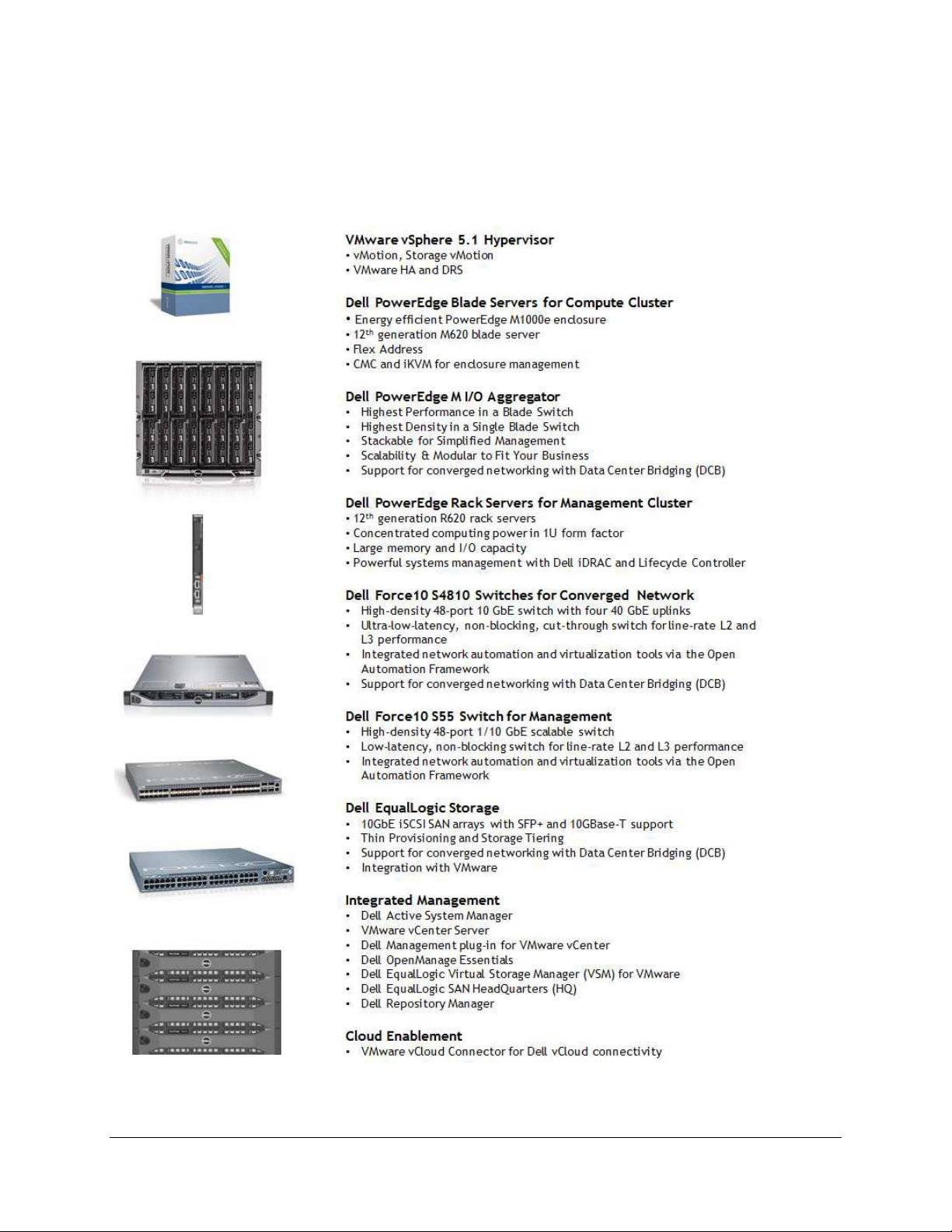
1.4. Overview
This section provides a high-level product overview of VMware vSphere, Dell PowerEdge blade servers,
Dell PowerEdge M I/O Aggregator, Dell Force10 S4810 switch, Dell Force10 S55 switch, and Dell
EqualLogic Storage.
12
Page 13

Active System Manager Solution Guide—Active System 800 (AS800)
Component
Details
VMware vSphere 5.1 Hypervisor
Up to 2x Dell PowerEdge M1000e chassis with up to
32x Dell PowerEdge M620 Blade Servers and
embedded VMware vSphere 5.1
Converged Fabric Switch
2xDell Force10 S4810
2x Dell PowerEdge M I/O Aggregator in each
Dell
PowerEdge M1000e chassis
Storage
Up to 8x Dell EqualLogic PS6110 series
arrays
Management Infrastructure
2x Dell PowerEdge R620 servers with
embedded VMware vSphere 5.1 hosting
management VMs.
1x Dell Force10 S55 used as a 1Gb out-of-
band management switch
Management components hosted in the
management infrastructure
Dell Active System Manager
VMware vCenter Server
Dell Management Plug-in for VMware
vCenter
Dell OpenManage Essentials
Dell EqualLogic Virtual Storage Manager
(VSM) for VMware
Dell EqualLogic SAN Headquarters (HQ)
VMware vCloud Connector
Dell Repository Manager
Table 1 lists the Active System Manager solution for the Active System 800-supported components.
Table 1. Active System 800-Supported Components
13
Page 14

Active System Manager Solution Guide—Active System 800 (AS800)
Configuration
Support
M1000e chassis and supported blade types (M620)
Support firmware images as per the
Active System Manager solution for Active
System 800
Dell Force10 Top-of-Rack (ToR) S4810 switches
Supported FTOS and base configuration will
be packaged in the virtual appliance. The
base configuration should be updated for
management IP and virtual LAN (VLAN) per
data center deployment need.
Dell EqualLogic PS6110 Storage Array
Supported firmware versions will be
packaged in the virtual appliance.
VMware vCenter 5.1 for virtual machine (VM) workloads
Supported ESXi 5.1 image will be bundled
in the virtual appliance
ESXi 5.1 installation support on blade servers
Virtual Appliance Filenames
Platform
Dell-ActiveSystemManager-7.0.0.xyztp_VMware.zip
VMware vCenter 5.1
Dell-ActiveSystemManager-7.0.0.xyztp_Microsoft.zip
Microsoft Server 2012 with Hyper-V
1.5. Active System 800-Supported Configurations
Table 2 lists the Active System Manager solution for the Active System 800-supported configurations.
Table 2. Active System 800-Supported Configurations
1.6. Deployment Options
The Active System Manager solution for Active System 800 is packaged as a virtual appliance and is
made available for VMware vCenter 5.1 and the Windows Server 2012 System Center Virtual Machine
Manager (SCVMM); see Table 3:
Open Virtualization Format (OVF) for VMware—The disk format is VMware virtual
machine disk (VMDK).
Hyper-V virtualization environment—The disk format is virtual hard disk (VHD) for
Hyper-V.
Table 3. Deployment Options
14
Page 15

Active System Manager Solution Guide—Active System 800 (AS800)
Specification
Prerequisite
Active System 800 units connected
per the Active System 800
Reference Architecture and
Design Guidelines
Management server is configured
per the Active System 800
Reference Architecture and
Design Guidelines
Firmware and BIOS Requirements
All equipment must be configured with firmware versions as
listed in section Appendix C—Firmware and Software Base
Lineup
For the Active System 800 chassis,
blade server, and IO aggregators:
CMC for M1000e chassis is configured and has the
management IP address and login credentials assigned
Server iDRAC and IOA is configured and has the
management IP address and login credentials assigned
using CMC Management interface.
The username (root) and password for CMC, IOA, and iDRAC
must be identical.
Force10 S4810 switches (Top-ofRack [ToR])
The management IP address is configured for the ToR
switches.
The A800 base configuration is applied on both
switches.
VLANs are created on the switches per the Active
System 800 deployment specification.
The virtual machine (VM) traffic VLANs will be created
dynamically by Active System Manager.
EqualLogic Storage Array
The group IP and management IP are configured for
Storage Array.
All storage array members are added to the group.
VMware vCenter 5.1
vCenter 5.1 is configured and accessible via the
management and hypervisor management network.
Appropriate licenses are deployed on the vCenter.
PXE Setup for server deployment
Details for deploying PXE Server is listed in section Appendix
G—PXE Setup Requirements. This setup is needed for PXE boot
of the servers only.
1.7. Deployment Prerequisites
Before using the Active System Manager solution for end-to-end provisioning of Active System 800
components, ensure that the prerequisites listed in Table 4 are in place.
Table 4. Deployment Prerequisites
15
Page 16
Active System Manager Solution Guide—Active System 800 (AS800)
2 Active System Manager Deployment
2.1 Deploying OVF
The Active System Manager Open Virtualization Format (OVF) can be imported on to an ESXi host using
the VMware OVF import process. When booted, the Active System Manager VM get its IP address from
an existing DHCP server. If the DHCP server is not configured, then assign the IP address manually to
the appliance.
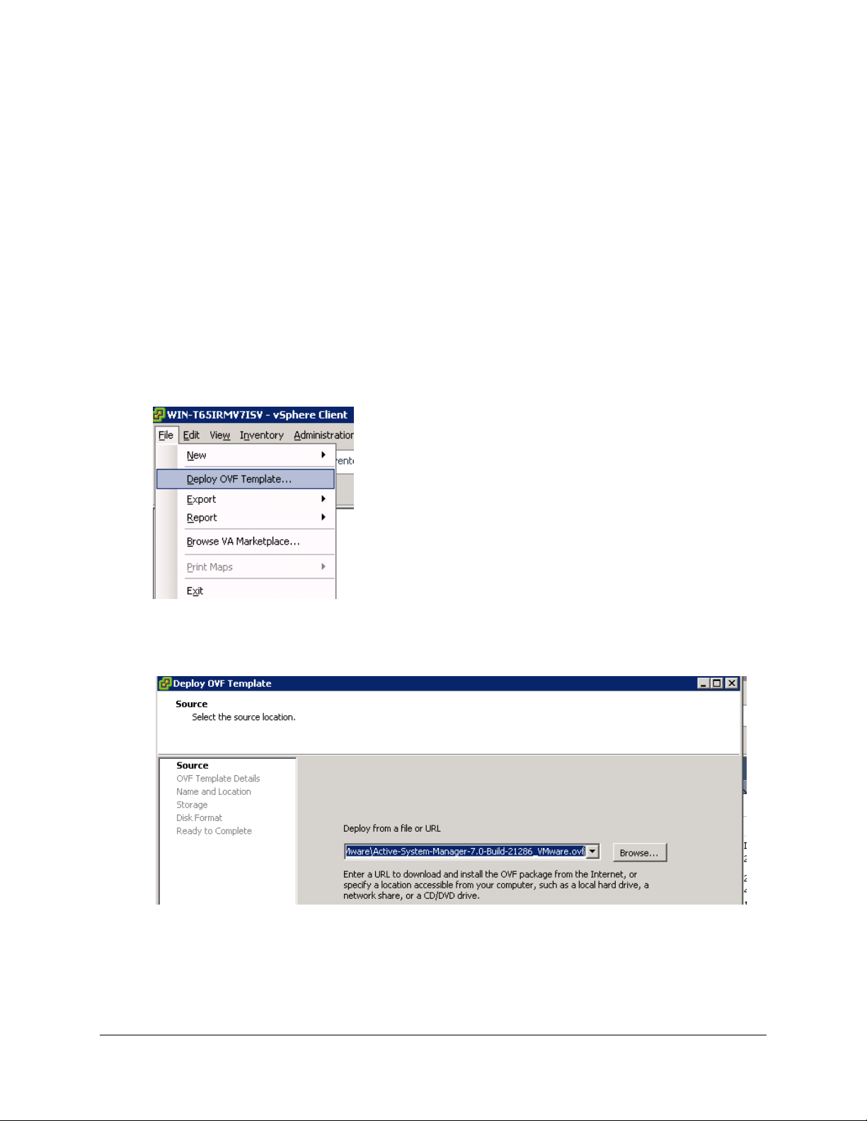
2.1.1 Importing OVF from the vSphere Client
To import OVF from the vSphere Client, perform the following steps:
1. On the vSphere Client menu, click File > Deploy OVF Template.
Figure 1. Deploy OVF Template Menu Option
2. Browse the OVF file and select Next.
Figure 2. Deploy OVF Template Source File Location
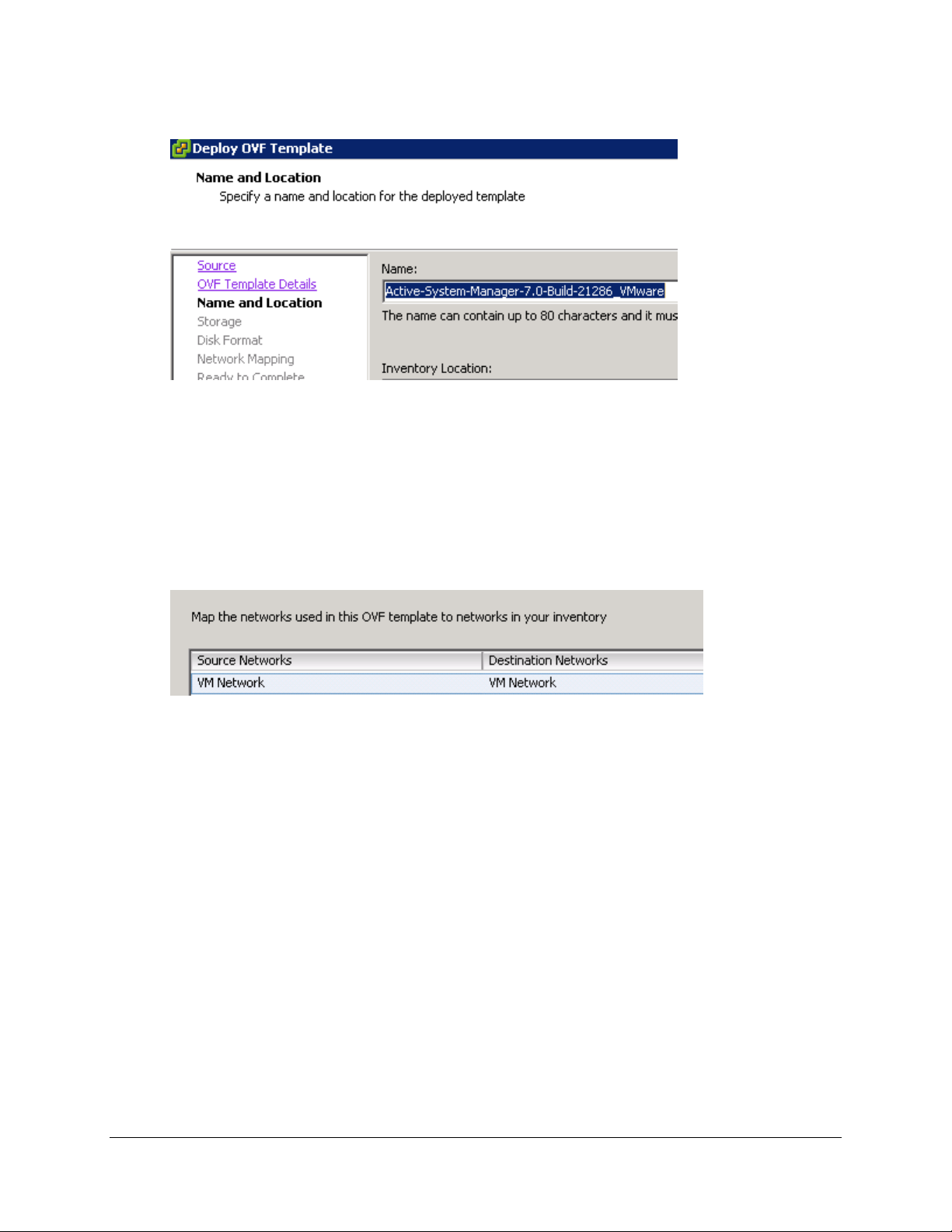
3. In the Name field, enter the VM name and click Next.
16
Page 17
Active System Manager Solution Guide—Active System 800 (AS800)
VM Access Credentials
Username/Password
Active System Manager server installation login
delladmin/delladmin
Active System Manager server root
root/Dell@123
Active System Manager application
admin/admin
Figure 3. Name and Location of the Deployed Template
4. Select the appropriate datastore name where the VM must be hosted.
5. Select the disk format. (Thin provisioning is supported and recommended.)
6. Select the network name. The VM must be mapped to the Hypervisor Management Network. All
networks (for example, OOB, Hypervisor Management, vMotion, iSCSI, and VM workloads) are
expected to be accessible from the appliance.
Figure 4. Mapping the Networks Used in the OVF Template
7. Table 5 lists the necessary key access credentials to use.
Table 5. Key Access Credentials
17
Page 18
Active System Manager Solution Guide—Active System 800 (AS800)
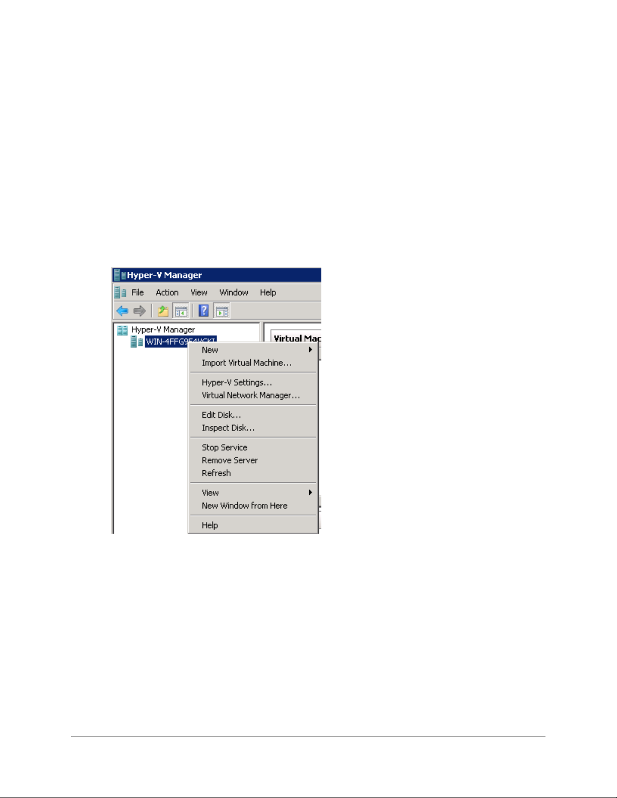
2.2 Deploying VHD
The Active System Manager Open Virtualization Format (VHD) can be imported on to a Hyper-V host
using the Hyper-V Manager > Import Virtual Machine option. When booted, the Active System Manager
VM gets its IP address from an existing DHCP server. If a DHCP server is not configured, manually assign
the IP address to the appliance.
2.2.1. Importing the VHD Using Hyper-V Manager
To import the VHD from the Hyper-V Manager, perform the following steps:
1. On the Hyper-V Manager dialog box, select a host, right-click and select Import Virtual
Machine.
Figure 5. Hyper-V Manager > Import Virtual Machine
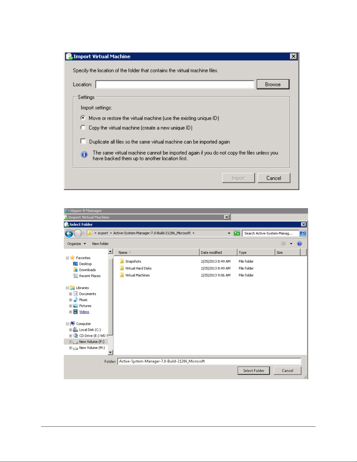
2. Click Browse, navigate to the location where the VDH is available in the extracted format, and
click Import.
18
Page 19
Active System Manager Solution Guide—Active System 800 (AS800)
Figure 6. Import Virtual Machine
Figure 7. Select Folder Option
19
Page 20
Active System Manager Solution Guide—Active System 800 (AS800)
3. Select a folder to house the VHD and click Select Folder.
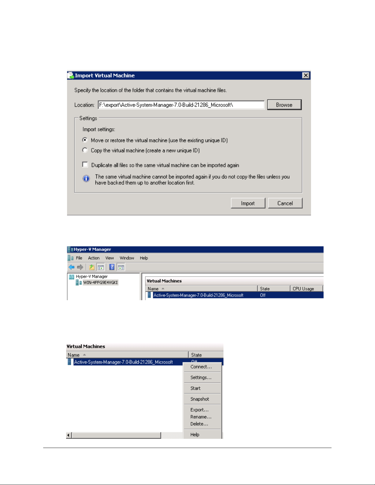
Figure 8. Import Settings
4. Verify the location that contains the virtual machine files and click Import.
Figure 9. Newly-Imported VM Displayed on the Hyper-V Manager
5. Select the VM and click Start to power on the VM.
Figure 10. Starting the VM
20
Page 21
Active System Manager Solution Guide—Active System 800 (AS800)
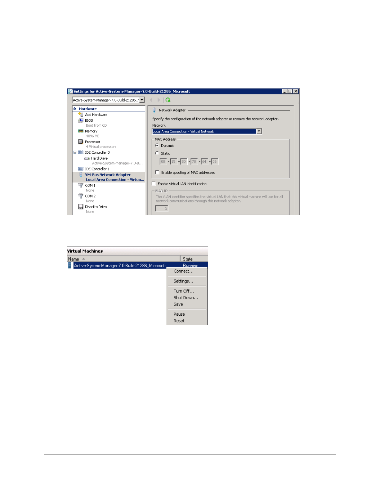
6. Select the network. The VM should be mapped to the Hypervisor Management Network. All the
networks (for example, OOB, Hypervisor Management, vMotion, iSCSI, and VM workloads) are
expected to be accessible from the appliance.
Figure 11. Selecting the Network
7. Click Connect to launch the console.
Figure 12. Connecting to Launch the Console
2.3 Assigning IP Address to the Active System Manager
To assign the IP Address to the Active System Manager appliance, perform the following steps:
1. On the vSphere or Hyper-V Manager client, select the deployed Active System Manager
appliance and open its console.
21
Page 22
Active System Manager Solution Guide—Active System 800 (AS800)
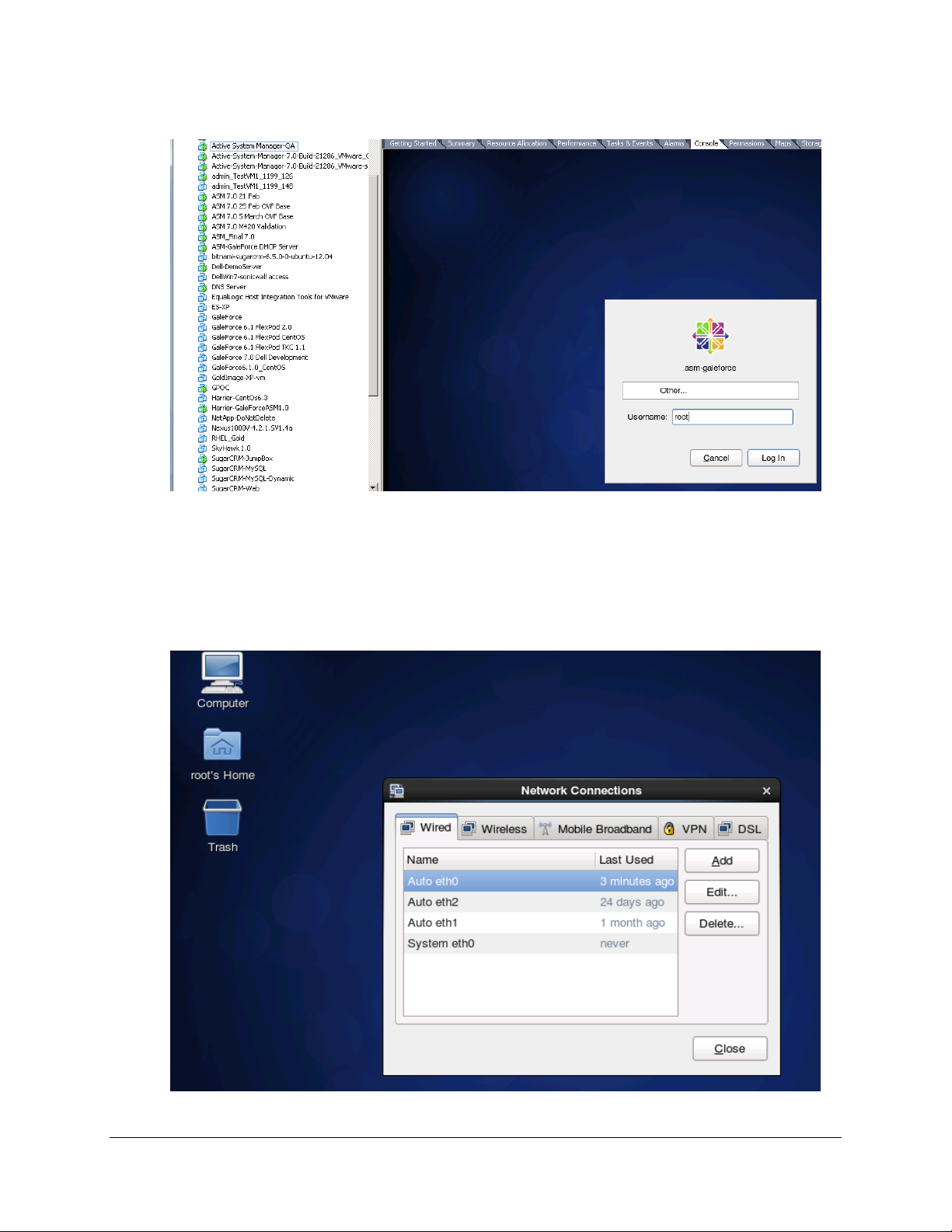
Figure 13. Logging In to the Active System Manager
2. Log in as the root user. Root user credentials are given Key Access Credentials.
3. Navigate to System >Preferences >Network Connections to launch the Network Connections
wizard.
Figure 14. Network Connections Wizard
22
Page 23
Active System Manager Solution Guide—Active System 800 (AS800)
4. Select the network interface card (NIC) appliance on which IP address should be configured
manually and click Edit.
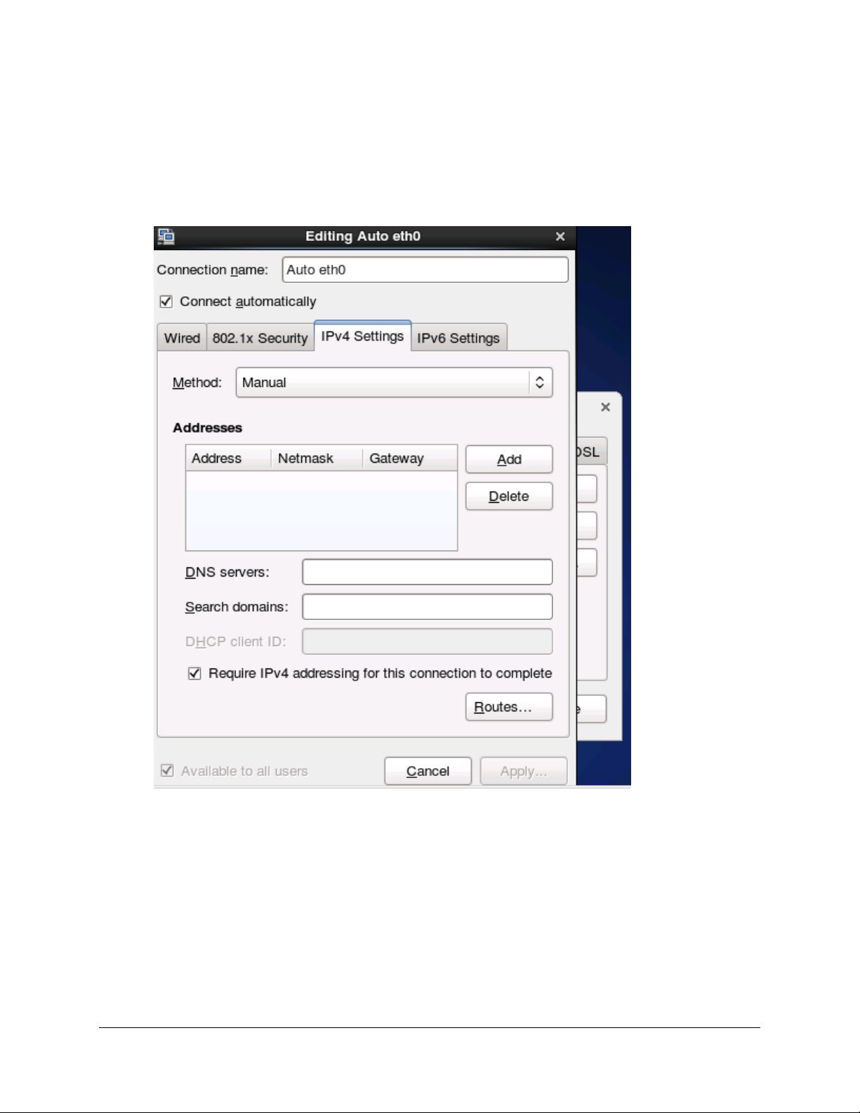
5. When the Editing dialog box displays (see figure below) update the IP address: select the IPv4
settings, click the Method drop-down list and select Manual.
Figure 15. Editing
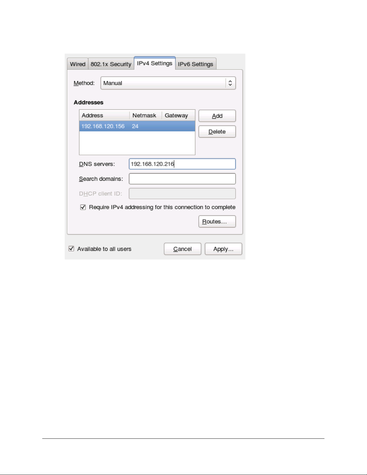
6. Click Add to provide the IP address and other networking details (for example, DNS), as shown
in the next figure.
23
Page 24
Active System Manager Solution Guide—Active System 800 (AS800)
Figure 16. Adding IP Addresses
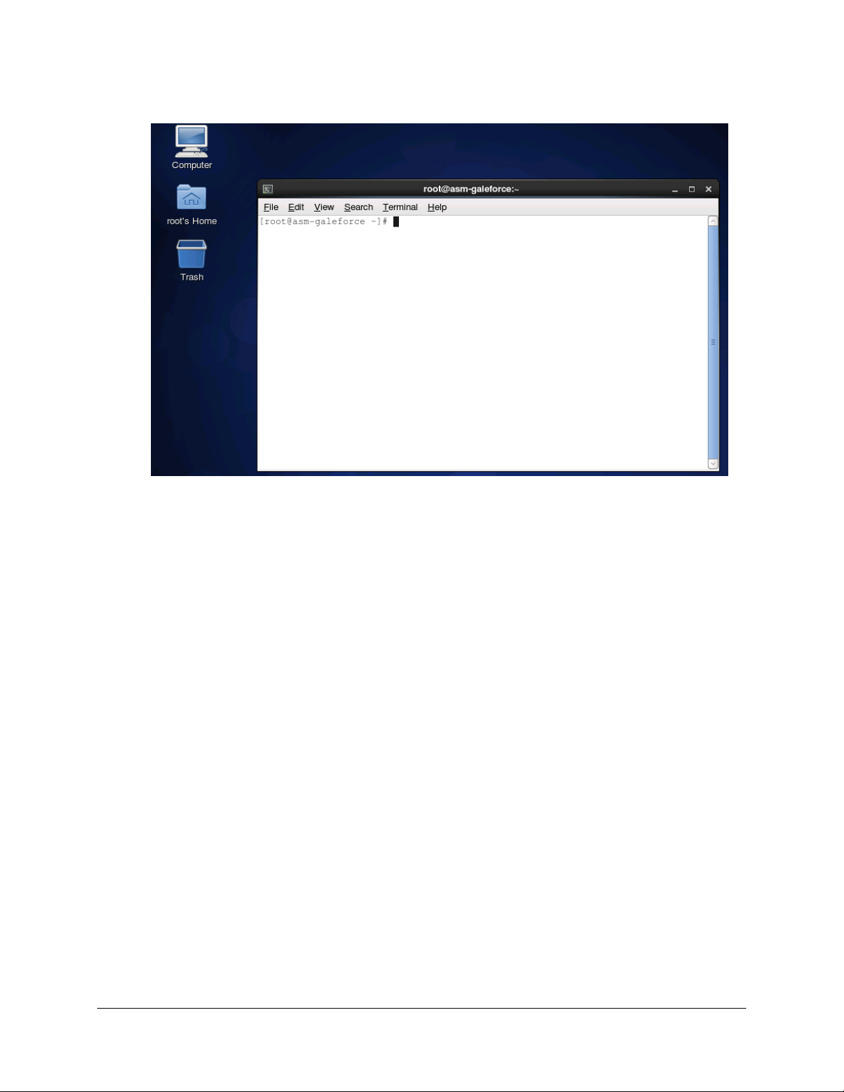
7. Click Apply. Once this is done, open the terminal by clicking Applications > System Tools >
Terminal.
24
Page 25
Active System Manager Solution Guide—Active System 800 (AS800)
Figure 17. Terminal Console
8. Execute the /etc/init.d/network restart command.
9. Log in to the appliance with the newly configured IP address. This will ensure that IP address is
configured correctly on appliance.
2.4 Installing the Active System Manager License
To install the Active System Manager license via the web client, perform the following steps:
1. Close all Active System Manager clients (web client and thick RCP client) connected to the
Active System Manager server. (The RCP client installation details are provided in the
subsequent sections.)
2. Log in to the Active System Manager Services as the delladmin/delladmin user.
3. If the license.lic file already exists, create a backup available under $HOME/asm-
galeforce/gf/common/etc/license.lic.
4. Copy the new license file as license.lic in the $HOME/asm-galeforce/gf/common/etc
directory.
25
Page 26

Active System Manager Solution Guide—Active System 800 (AS800)
2.5 Configuring Active System Manager Services
2.5.1 Starting Services
Appliance is configured to start Active System Manager services during start-up. Following are the steps
for starting the appliance manually.
1. Log in as the delladmin user. The password is listed in the 2.1 Deploying OVF section.
2. Execute the following command:
cd $HOME/asm-galeforce/gf/sbin
./startGF.sh
Note:
The Active System Manager services must not be started by the root user.
2.5.2 Stopping Services
Following are the steps for stopping the services manually.
1. Log in as the delladmin user. The password is listed in the 2.1 Deploying OVF section.
2. Execute the following command:
cd $HOME/asm-galeforce/gf/sbin
./stopGF.sh
2.5.3 Verifying Service Status
To verify that all Active System Manager services are up and running, perform the following steps:
1. Log in as the delladmin user. The password is listed in the 2.1 Deploying OVF section.
2. Run the following script to display the current status of all services, including the Oracle
database status:
cd asm-galeforce/gf/sbin
./gfstatus.sh
Below is sample output:
Active System Manager Services Status
Installation
---------------Release Version: 7.0
Build Number: 21286
Database
----------------
26
Page 27

Active System Manager Solution Guide—Active System 800 (AS800)
Vendor: Oracle (Ver: 11.2.0.1.0)
Host: asm-galeforce Port: 1521
Service name: DB11G
Status: Running
Active System Manager Service
---------------------------------Host: asm-galeforce Port: 40500 Secure Port: 50500
Enterprise: Dell
Lab: DEMO
Status: Running
Domain Services
----------------
1. Domain : System (Id: 1)
Description:
----------------------------------------------------- Session server
Host: asm-galeforce Port: 40500 Secure Port: 50500
Status: Running
2.6 Installing the Active System Manager Client
You can install the Active System Manager Client on the following platforms:
2.6.1 Installing Active System Manager Client Software on Windows
2.6.2 Installing the Active System Manager Client Software on Mac
2.6.3 Installing the Active System Manager Client Software on Linux
2.6.1 Installing Active System Manager Client Software on Windows
To install the Active System Manager Client software on a Microsoft Windows OS, perform the following
steps:
1. Download the Active System Manager installer, x64 version should be downloaded for x64 OS
and x32 should be downloaded for x32 based OS
2. On your desktop, click Start > Run > Browse, navigate to the setup.exe file, and click OK.
Alternatively, from your Windows Explorer window, navigate to the setup.exe file and doubleclick it.
A Security Warning window prompts you to run the file.
3. Click Run to enable the installation wizard to guide you through the installation process.
Note:
If an existing version of the client is on the client machine, invoking the installer prompts you to select
to uninstall the existing version already on the system. Once selected, the installer uninstalls the
existing version and then exits. You must perform the originally intended install after uninstalling the
previous version as a single step.
4. Click Finish to complete the installation process.
27
Page 28
Active System Manager Solution Guide—Active System 800 (AS800)
2.6.2 Installing the Active System Manager Client Software on Mac
To install the Active System Manager Client software on a Mac OS, perform the following steps:
1. Download the ActiveSystemManager-macosx.x86_64_7.0.0_xyzt.zip file.
2. Unzip the file into a specific folder destination on your hard drive.
3. Create the Active System Manager folder and move the file contents to this location.
4. Execute the Active System Manager.app file.
2.6.3 Installing the Active System Manager Client Software on Linux
To install the Active System Manager Client software on Linux, perform the following steps:
1. Download the ActiveSystemManager-linux.gtk.x86_7.0.0_xyzt.zip file.
2. Unzip the file into a specific folder destination on your hard drive.
3. Create the Active System Manager folder and move the file contents to this location.
4. In the console, execute the Active System Manager file.
2.6.4 Accessing Active System Manager Using the Windows Client Software
To access the Active System Manager software using the Windows Client software, perform the
following steps:
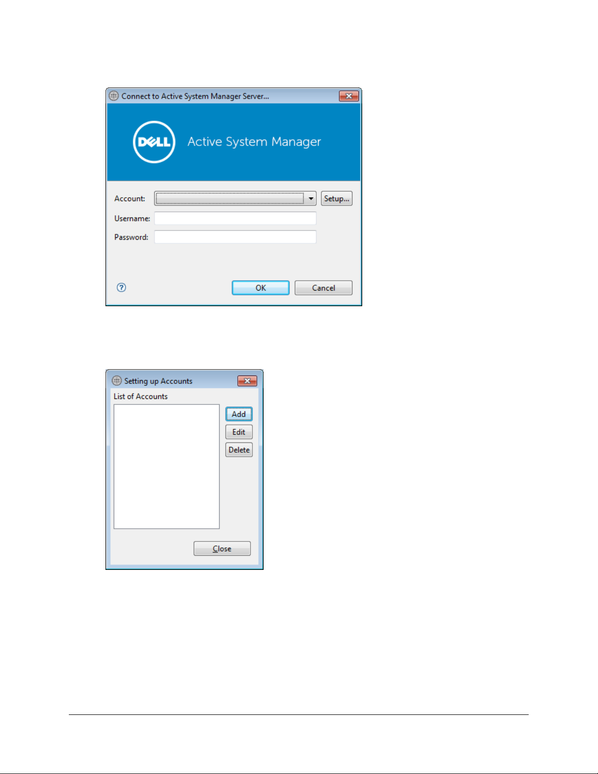
1. Launch the client software application.
Figure 18. Launching the Active System Manager Client Software
2. Click Setup to create the account setup.
28
Page 29
Active System Manager Solution Guide—Active System 800 (AS800)
Figure 19. Connecting to the Active System Manager Server
3. On the Setting Up Accounts dialog box, click Add. Name the account as the connection to the
Active System Manager appliance.
Figure 20. Setting Up Accounts
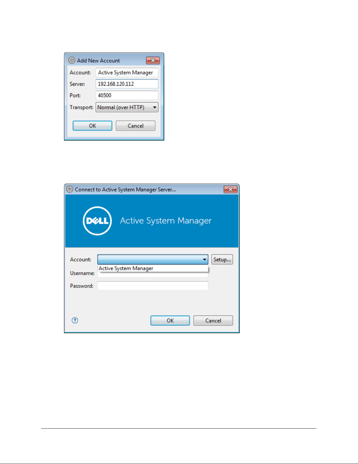
4. Provide the name of the connection and IP address of the appliance. The name of the
connection can be any descriptive as shown in the following figure.
29
Page 30
Active System Manager Solution Guide—Active System 800 (AS800)
Figure 21. Adding New Account
5. Click OK and close the Setting Up Account dialog box.
6. Select the account created in earlier step 4.
Figure 22. Logging In to the Active System Manager
7. Provide the username and the password for the appliance. The default username and password
is admin/admin. Click OK to launch the Active System Manager application.
30
Page 31

Active System Manager Solution Guide—Active System 800 (AS800)
3 Active System Manager Setup
This section captures the sequence of steps which should be followed within Active System Manager for
managing deploying the blade servers in the Active System 800.
3.1 User and Group Management
You can manage users and groups within the Active System Manager either directly (by entering the
values for individual users and groups from the Windows Client graphical user interface [GUI]), or by
importing users from an external repository, such as Lightweight Directory Access Protocol (LDAP),
Active Directory (AD), or Network Information Service (NIS).
For user management, log in to the Windows client and navigate to Tools > User and Groups. The
Security Management—Users and Groups dialog box displays.
Note:
Set the time zone to match the time on the workstation that the Active System Manager client is
installed.
Figure 23. Security Management—Users and Groups
For details on user and group administration, see the “User Profile Management” chapter in the Active
System Manager User Guide, which is downloadable from the Active System Manager 7.0 web portal
(Help menu) or from the Thick client(Eclipse-based).
31
Page 32

Active System Manager Solution Guide—Active System 800 (AS800)
3.2 Discovering Active System 800 Components
Discovery of the Active System 800 components includes:
Dell M1000e Chassis
Dell M620 Blade servers
Dell PowerEdge M I/O Aggregators
Force10 Top-Of-Rack (ToR) S4810 switches
Dell EqualLogic Storage Array
VMware vCenter Server components
3.2.1 Initiating Discovery
To initiate the Discovery process, perform the following tasks in this order:
3.2.1.1 Configuring Discovery Setup
3.2.1.2 Adding Details for the Active System
3.2.1.3 Adding vCenter System Properties
3.2.1.4 Starting the Discovery Process
3.2.1.1 Configuring Discovery Setup
To configure Discovery settings, perform the following steps:
1. Connect to the Active System Manager Client using user credentials with Administrator
privileges.
2. Select Tools >Discovery >Setup.
Figure 24. Discovery Menu Options
The Discovery Configuration Setup page displays.
32
Page 33

Active System Manager Solution Guide—Active System 800 (AS800)
Figure 25. Discovery Configuration Setup
3.2.1.2 Adding Details for the Active System 800 Unit
To add details for the Active System 800 unit, click Add System. This feature displays names for Active
System 800 components that will be discovered; for example:
Dell Chassis
Dell EqualLogic Storage Array
Dell Force10
Figure 26. Adding System Details
3. Select the individual components and provide the required IP address/login credentials per the
figure.
33
Page 34

Active System Manager Solution Guide—Active System 800 (AS800)
Figure 27. Dell Chassis Element Properties
o Assettag—Required. Unique key or name used to import or identify the Dell
M1000e Chassis within Active System Manager. For example Assettag
Dell_Chassis_001 (a unique name) can be used to track the chassis in Active
System Manager
o Username—Username to access and manage the Dell M1000e Chassis.
o Password—Password to access and manage the Dell M1000e Chassis.
o IP Address—Required. IP address for the Dell M1000e Chassis CMC. The CMC
should be IP reachable from the Active System Manager server.
4. Provide the following element properties for the Dell EqualLogicStorageArray system (Figure 7):
Figure 28. EqualLogicStorayArray Element Properties
o Assettag—Required. Unique key or name for the EqualLogic Storage Array,
which is used to import or identify an EqualLogic Storage Array in the Active
System Manager. For example, Assettag Dell_EqualLogic_PS6100_1 (a unique
name) can be used to track the EqualLogic array in Active System Manager.
o Username—Group username to access and manage the EqualLogic Storage
Array.
o Password—Group password to access and manage the EqualLogic Storage Array.
o IP Address—Required. Group Management IP address for the EqualLogic Storage
Array. Group Management IP should be reachable (via ping to test) from the
ASM server Group IP of the EqualLogic Array should be IP reachable from the
Active System Manager server.
34
Page 35

Active System Manager Solution Guide—Active System 800 (AS800)
The following figure displays an example of how to edit to the /etc/hosts file and how it should be
saved: Save file > press Esc > type :wq! > press Enter.
Figure 29. Editing and Saving the /etc/hosts File
Note:
Ifthere are multiple storage groups, there should be an entry for each of the Storage Group in the
Discovery Configuration Setup view. For adding a new element in an existing Active System 800 unit,
click Add Element, select Dell EqualLogicStorageArray, and provide required details to initiate
discovery.
Figure 30. Adding the Dell EqualLogicStorageArray Element
5. For Dell Force10 Switch (ToR) discovery, provide the following element properties and
discovery attributes:
35
Page 36

Active System Manager Solution Guide—Active System 800 (AS800)
Figure 31. Dell Force10 Element Properties and Discovery Attributes
36
Page 37

Active System Manager Solution Guide—Active System 800 (AS800)
o Assettag—Required. Unique key or name for Dell Force10 Switch which is used
to import or identify the Force10 Switch in Active System Manager. For
example, Assettag Dell_Force10-S4810_1 (a unique name) can be used to track
the Force10 Switch in Active System Manager
o Username—Username to manage the Force10 switch.
o Password—Password to manage the Force10 switch.
o IP Address—Required. Management IP address for the Force10 switch. This
should be IP reachable from the Active System Manager server.
Role—(Optional) Top / Bottom.
SupportedVLANIDs—VLAN IDs that could be provisioned on the Top-Of-
Rack (ToR) switch. Sample input format (2..1024); the switch supports
a VLAN range from 2 to 1,024.
Terminal Server IP Address—Optional. Required if switch to managed
using the Terminal Server port.
Terminal Server Port— Optional. Required if switch to managed using
Terminal Server port.
Terminal Server Username—Optional. Terminal Server username (if
configured)
Terminal Server Password—Optional. Terminal Server password (if
configured)
3.2.1.3 Adding vCenter System Properties
To add vCenter system properties, perform the following steps:
1. On the Active System Manager > System > vCenter configuration, click Add vCenter.
2. For VMware vCenter discovery, provide the following system properties:
Figure 32. Adding vCenter System Properties
o Name—Unique key or name for VMware vCenter which is used to import or
identify vCenter in the Active System Manager.
o Username—Username to access and manage the vCenter. This user must have
full administrator rights to the vCenter. If the vCenter Server is part of a
Windows Domain, then enter the username as username@domain.
o Password—Password to access and manage the vCenter.
o IP Address—IP address for the vCenter application. This must be IP reachable
from the Active System Manager server.
37
Page 38

Active System Manager Solution Guide—Active System 800 (AS800)
3.2.1.4 Starting the Discovery Process
To start the Discovery process, perform the following steps:
1. Connect to the Active System Manager Client using user credentials with Administrator
privileges.
2. On the menu bar, click Tools >Discovery >Start, which initiates the discovery process for
components that were set up during the discovery configuration setup.
Figure 33. Tools > Discovery > Start
Note:
You can view the discovery progress indication at the task bar shown in the bottom of
the client.
Ifdiscovery progress is initiated again when a discovery process is already in progress,
the Active System Manager user is prompted with a message, indicating the same.
3. After completing the Active System 800 components discovery, update the following
information manually in the Active System Manager for all blade servers. These parameters will
be used for configuring the ESXi Server with appropriate IP Address, hostname, iSCSI IP Address
etc.
This information can be updated by using the multi-editor feature or by opening individual
server instances. You can launch the multi-editor by selecting multiple server instances and
then clicking Open with Multi-Editor.
38
Page 39

Active System Manager Solution Guide—Active System 800 (AS800)
Figure 34. Open with Multi-Editor
The following parameters must be updated:
ISCSIvNICIPAddresses—Space-separated list of IP addresses to be assigned to iSCSI
virtual network interface cards (vNICs). For example, for updating information for
“vmnic6 vmnic7” using the Update Port Group with iSCSI VLAN operation, the value can
be in the 192.168.120.XX 192.168.120.YY format. as an example and will depend on the
environment subnet range. The IP Addresses needs to be separated by a space “ “
iSCSIChapUsername—iSCSI Chap username used to access volume of EqualLogic Storage
Array
iSCSIChapSecret—iSCSI Chap secret corresponding to iSCSI Chap username.
ServerHostname—Hostname to be assigned to the ESXi server.
ServerDomainName—Domain name to be assigned to the ESXi server.
ServerNameServer—Name server to be assigned to the ESXi server. If there are
multiple name servers, a comma “,” separated valued should be provided.
39
Page 40

Active System Manager Solution Guide—Active System 800 (AS800)
ServerGateway—Gateway for the ESX server.
ServerNetmask—Netmask for the management NIC of ESX server.
ServerIPAddress—IP address that must be assigned to management NIC of the ESX
server. Ifthe hypervisor must retrieve an IP address from the DHCP server, leave this
parameter blank.
ServerPassword—Server root password to be assigned during unattended installation.
vMotionIPAddress—TBD
vMotionSubnet (netmask)—TBD
3.3 Software Repositories Available in the Active System
Manager Virtual Appliance
The following repositories are pre-packaged and available in the Active System Manager virtual
appliance:
Applicable for Dell Servers—“PXE bootable images”, where the repository has the ESXi
PXE bootable installer image already configured and “ISO bootable images” where the
ESXi ISO bootable installer image is available.
Applicable for Dell EqualLogic Storage—EqualLogic Storage Firmware.
The repository has EqualLogic firmware images configured (EqualLogic Storage
Resource Pools)
ToR Switch Configurations and Images—The repository has switch images and a base
configuration configured.
VMware ESXi images
Figure 35. Software Repositories
40
Page 41

Active System Manager Solution Guide—Active System 800 (AS800)
3.3.1 Updating Repository Elements for Firmware Images on EqualLogic
Firmware Repo
The EqualLogic StorageArray repository contains firmware images to be used for updating the firmware
on EqualLogic Storage Arrays.
To update these repository elements, perform the following steps:
1. Open the Software Repositories view in the setup perspective by clicking Setup > Software
Repositories on the client.
Figure 36. Software Repositories View
2. Right-click the view and select Repositories.
The Custom Repository—Select Repository Type dialog box displays.
41
Page 42

Active System Manager Solution Guide—Active System 800 (AS800)
Figure 37. Selecting Repository Type to Update
3. Click the Software Repository > Existing radio buttons.
4. Using the drop-down menu, select the Repository Type and click Next.
5. Update the IP address, username, password, and base directory (location on the server where
the firmware images are present, it can be the access information for the Active System
Manager appliance as appliance is shipped with latest firmware images; otherwise, it can the
access information for the remote server having the firmware images residing on it, the server
should be SSH reachable from the Active System Manager appliance) for the image server, and
click Next.
The Custom Repository—Update EqualLogic Firmware Repository dialog box displays; see
Figure 19.
42
Page 43

Active System Manager Solution Guide—Active System 800 (AS800)
Figure 38. Update EqualLogic Firmware Repository
6. Click Finish.
Note:
Ifa new image is added to the appliance, skip this step.
43
Page 44

Active System Manager Solution Guide—Active System 800 (AS800)
Figure 39. Repository Elements Discovery and Association
7. Click Discover to display all the firmware images available on the image server.
Figure 40. Repository Elements Discovery and Association
44
Page 45

Active System Manager Solution Guide—Active System 800 (AS800)
8. Click Associate to associate the image file with the required Resource Types (Dell EqualLogic
Storage Array and EqualLogic Storage Pool).
Figure 41. Associating Resource Types
Figure 42. Associating Inventory
9. Select resource types and click OK.
45
Page 46

Active System Manager Solution Guide—Active System 800 (AS800)
3.3.2 Updating Repository Elements for EqualLogic Storage Resource Pools
The EqualLogic Storage Resource Pool repository contains the information of the Storage Pools
available on EqualLogic Storage Arrays.
To update these repository elements, perform the following steps:
1. Open the Software Repositories view in the setup perspective.
2. Right-click the view and select Repositories.
The Custom Repository—Select Repository Type dialog box displays.
Figure 43. Selecting Repository Type to Update
3. Click the Software Repository > Existing radio buttons.
4. Using the drop-down menu, select EqualLogic Storage Resource Pools and click Next.
46
Page 47

Active System Manager Solution Guide—Active System 800 (AS800)
The Software Repository—Update EqualLogic Resource Pool Repository dialog box displays.
Figure 44. Update EqualLogic Resource Pool Repository
5. Update the Host, Username, and Password parameters. These parameters correspond to
storage group Management IP address, group username, group password respectively, and click
Next.
6. Click Finish.
Note:
Ifa new resource pool is added and information needs to be updated, skip this step.
7. Click Discover to display all the storage pools available on the Storage Array.
47
Page 48

Active System Manager Solution Guide—Active System 800 (AS800)
Figure 45. Discovering New Elements
8. Right-click the selected Resource Pool and update the Type to Image File, and click Finish.
Figure 46. Repository Elements Discovery and Association
9. Click Associate to associate the storage pools with the required Resource Types (Dell
EqualLogic-PS6110 and EqualLogic Storage Pool), and click Finish.
48
Page 49

Active System Manager Solution Guide—Active System 800 (AS800)
Figure 47. Associating Resource Types
3.3.3 Updating Repository Elements for PXE Bootable Images
To update these repository elements, perform the following steps:
1. Open the Software Repositories view in the Setup perspective.
Figure 48. Software Repositories View
2. Right-click the view and select Repositories.
The Custom Repository—Select Repository Type dialog box displays.
49
Page 50

Active System Manager Solution Guide—Active System 800 (AS800)
Figure 49. Selecting Repository Type to Update
3. Click the Software Repository > Existing radio buttons.
4. Using the drop-down menu, select PXE Bootable Images and click Next.
The Update Trivial File Transfer Protocol for PXE Boot dialog box displays.
Figure 50. Update TFTP for PXE Boot
50
Page 51

Active System Manager Solution Guide—Active System 800 (AS800)
5. Update the Host attribute value with the IP address of the Active System Manager appliance.
6. The Username and Password are configured with default appliance username and password.
These needs to be updated Ifthe default username/password is updated.
7. Click Next to display the list of repository files.
8. Click Finish.
Note:
Ifa new resource pool is added and information needs to be updated, skip this step.
Figure 51. Discovering New Elements
9. Click Discover to initiate the discovery of the repository files. This step is required only if a
new image is added to the repository.
This will list the discovered element in the repository.
51
Page 52

Active System Manager Solution Guide—Active System 800 (AS800)
Figure 52. List of Repository Files
10. Right-click the selected discovered elements and update the Type to Image File, and click
Finish.
Figure 53. Updating Discovered Elements Type to Image File
3.3.4 Updating Repository Elements for ISO Bootable Images
To update these repository elements, perform the following steps:
1. Open the Software Repositories view in the Setup perspective.
Figure 54. Software Repositories View
2. Right-click the view and select Repositories.
The Custom Repository—Select Repository Type dialog box displays.
52
Page 53

Active System Manager Solution Guide—Active System 800 (AS800)
Figure 55. Selecting Repository Type to Update
3. Click the Software Repository > Existing radio buttons.
4. Using the drop-down menu, select ISO Bootable Images and click Next.
The Update Trivial File Transfer Protocol for ISO Boot dialog box displays.
53
Page 54

Active System Manager Solution Guide—Active System 800 (AS800)
Figure 56. Update TFTP for PXE Boot
5. Update the Host attribute value with the IP address of the Active System Manager appliance.
6. The Username and Password are configured with default appliance username and password.
These needs to be updated if the default username/password is updated.
7. Click Next to display the list of repository files.
8. Click Finish.
Note:
If a new resource pool is added and information needs to be updated, skip this step.
9. Click Discover to initiate the discovery of the repository files. This step is required only ifa new
ISO image is added to the appliance.
This will list the discovered element in the repository.
54
Page 55

Active System Manager Solution Guide—Active System 800 (AS800)
Figure 57. List of Repository Files
10. Right-click the selected discovered elements and update the Type to Image File, and click
Finish.
Figure 58. Updating Discovered Elements Type to Image File
55
Page 56

Active System Manager Solution Guide—Active System 800 (AS800)
Figure 59. Repository Properties
11. Update the Host attribute with the IP address of the VM appliance.
12. Click Next to display the list of repository files.
13. Click Finish.
Note:
Ifa new resource pool is added and information needs to be updated, skip this step.
56
Page 57

Active System Manager Solution Guide—Active System 800 (AS800)
Figure 60. Discovering New Elements
14. Click Discover to initiate the discovery of the repository files.
The list of discovered elements in the repository displays.
Figure 61. List of Repository Files
15. Right-click the selected discovered elements, update the Type to Configuration File, and click
Finish.
57
Page 58

Active System Manager Solution Guide—Active System 800 (AS800)
Figure 62. Updating Discovered Elements Type to Configuration File
16. Click Associate to associate the selected element with the Dell Force10 resource type and
click Finish.
Figure 63. Associating Resource Types
58
Page 59

Active System Manager Solution Guide—Active System 800 (AS800)
3.3.5 Updating Repository Elements for VMware Baseline Images
This repository contains VMware baseline images for creating VM clones.
To update the repository elements for VMware baseline images, perform the following steps:
1. Open the Software Repositories view in the Setup perspective.
Figure 64. Software Repositories View
2. Right-click the view and select Repositories.
The Custom Repository—Select Repository Type dialog box displays.
Figure 65. Selecting VMware Baseline Images Repository
3. Click the Software Repository > Existing radio buttons.
4. Using the drop-down menu, select VMware Baseline Images, and click Next.
The Repository Properties dialog box displays.
59
Page 60

Active System Manager Solution Guide—Active System 800 (AS800)
Figure 66. Repository Properties
5. Update the VMware vCenter host (IP address), username, and password.
6. Click Next to display the list of repository files.
7. Click Discover to initiate the discovery of the repository files.
The list of VMs managed by the vCenter displays.
60
Page 61

Active System Manager Solution Guide—Active System 800 (AS800)
Figure 67. List of Repository Files
8. Right-click the selected discovered element, select Set Type > Image File, and click Finish.
Figure 68. Updating Discovered Elements Type to Image File
9. Click Associate to associate the selected element with the VMware VM resource type and click
Finish.
Figure 69. Associating Resource Types
61
Page 62

Active System Manager Solution Guide—Active System 800 (AS800)
4 Physical Templates and Orchestration
4.1 Multiple Blade Server for Cluster Provisioning
Template ‘Cluster - VMware ESXi 5.1 Hypervisor deployment ISO boot’ and ‘Cluster - VMware ESXi 5.1
Hypervisor deployment PXE boot’ can be used for installing ESXi 5.1 on an SD card/hard disk,
respectively, using PXE / ISO Boot. You can specify one or more blade servers using this template for
creating a cluster.
Figure 70. Multiple Blade Server for Cluster Provisioning
When this template is scheduled, this template performs the following sequence of operations:
1. Reserves single or multiple VLANs for VM traffic using a VLAN component. Ifthe VLAN reserved
in the session is not already configured on the ToR switches, then the VLANs are created and
tagged to appropriate port-channels.
2. IOA Configuration
a. The VLAN IDs provided for Network1, Network2, Network4, and VLAN component in the
physical template are created on the IOA server facing interfaces as Tagged VLANs.
b. The Native VLAN ID provided for Network1 is added as Un-Tagged VLAN on the server
facing interface.
c. The Native VLAN ID is mandatory for PXE boot scenario.
3. NIC Partitioning
a. NIC Partitioning is enabled on the CAN.
b. NIC Partitioning is only supported Broadcom CNA.
4. Set NIC Attributes
a. Configure the Min and Max Bandwidth
b. Enable / Disable iSCSI Offload on the NIC Partitions
c. Enable LAN Mode
d. Enable the Legacy boot protocol for PXE Boot scenario
62
Page 63

Active System Manager Solution Guide—Active System 800 (AS800)
5. Create the ISO files for each server dynamically based on the Server IP Address, Hostname,
Name server values provided in the database.
6. Mount the ISO using iDRAC Virtual Media on all the Servers and initiate the installation process.
7. Configure the vSwitch configuration
a. Create the vSwitch and port-groups based on Active System 800 deployment
specification
b. Tag the port-groups with appropriate VLANs as specified in the template
c. Create iSCSI Port-groups and install / configure the MEM VIBs
8. Create a volume of the EqualLogic Storage Array
a. The new volume is created per physical session based on the size specified in the
Orchestration input.
b. The authentication of the new volume is configured based on the Chap username and
secret key specified in the inventory database of the servers.
9. Create vCenter Cluster / Datacenter (if not already exists) on the specified vCenter. The
cluster is created with default settings (DRS - On, HA - On, EVC - Disabled).
Note: The cluster name passed as an argument must not be the Management cluster.
10. Add hosts to the vCenter cluster.
11. The datastore created in the orchestration is used for provisioning the VM in the logical
workload templates. Provides access to Gold volume and using Gold volume, creates base VMs.
12. Installs EqualLogic MEM modules. The MEM package is transferred to the volume created in the
above step to enable the installation.
13. Registers base VMs to the vCenter for logical template provisioning.
Note:
You should update the template for necessary inputs before scheduling this template for cluster
provisioning. For details, see the
63
Page 64

Active System Manager Solution Guide—Active System 800 (AS800)
4.5 Updating Physical Templates section.
64
Page 65

Active System Manager Solution Guide—Active System 800 (AS800)
4.2 Single Blade Server for Standalone ESX Host Provisioning
Template ‘Standalone—VMware ESXi 5.1 Hypervisor deployment with SD Card with vSwitch’ and
‘Standalone – VMware ESXi 5.1 Hypervisor deployment with HDD with vSwitch’ can be used for
installing ESXi 5.1 on an SD card/hard disk, respectively, using PXE / ISO Boot. User could specify one
or more blade servers for standalone ESXi host provisioning.
Figure 71. Single Blade Server for Standalone ESX Host Provisioning
When this template is scheduled, this template performs the following sequence of operations:
1. Reserves single or multiple VLANs for VM traffic using a VLAN component. Ifthe VLAN reserved
in the session is not already configured on the ToR switches then the VLAN are created and
tagged to appropriate port-channels.
2. IOA Configuration
a. The VLAN IDs provided for Network1, Network2, Network4 and VLAN component in the
physical template are created on the IOA server facing interfaces as Tagged VLANs.
b. The Native VLAN ID provided for Network1 is added as Un-Tagged VLAN on the server
facing interface.
c. The Native VLAN ID is mandatory for PXE boot scenario.
3. NIC Partitioning
a. NIC Partitioning is enabled on the CAN.
b. NIC Partitioning is only supported Broadcom CNA.
4. Set NIC Attributes
a. Configure the Min and Max Bandwidth
b. Enable / Disable iSCSI Offload on the NIC Partitions
c. Enable LAN Mode
d. Enable the Legacy boot protocol for PXE Boot scenario
5. Create the ISO files for each server dynamically based on the Server IP Address, Hostname,
Name server values provided in the database.
6. Mount the ISO using iDRAC Virtual Media on all the Servers and initiate the installation process.
65
Page 66

Active System Manager Solution Guide—Active System 800 (AS800)
7. Configure the vSwitch configuration
a. Create the vSwitch and port-groups based on Active System 800 deployment
specification
b. Tag the port-groups with appropriate VLANs as specified in the template
c. Create iSCSI Port-groups and install / configure the MEM VIBs
8. Create a volume of the EqualLogic Storage Array
a. The new volume is created per physical session based on the size specified in the
Orchestration input.
b. The authentication of the new volume is configured based on the Chap username and
secret key specified in the inventory database of the servers.
9. Add hosts to the vCenter at datacenter level.
10. The datastore created in the orchestration is used for provisioning the VM in the logical
workload templates. Provides access to Gold volume and using Gold volume, creates base VMs.
11. Installs EqualLogic MEM modules. The MEM package is transferred to the volume created in the
above step to enable the installation.
12. Registers base VMs to the vCenter for logical template provisioning.
4.3 Associated Orchestrations with Cluster and Standalone Host
Templates
Each physical template has three orchestrations associated with it:
Figure 72. Orchestrations
66
Page 67

Active System Manager Solution Guide—Active System 800 (AS800)
1. On-demand—VMFS Datastore Provision TBD Per Jerry Ness, need more detail around the
missing task that a VMFS datastore LUN for the GOLD images must be initially created on the
storage before the logical templates can be run.
This orchestration can be executed on-demand when the session is in a Running state.
2. Setup—Configures the ESXi Servers using PXE Boot
This orchestration executes when template provisioning starts and the session is in the Setting
Up state.
3. Teardown—Cleanup-Orchestration
This orchestration executes when template provisioning start and session is in Setting-up state.
4.4 Additional Storage for Cluster or Host
For additional VMFS storage or datastore need on a cluster or standalone ESXi host reserved through
the Active System Manager, you can execute on-demand orchestration from a Running session.
For executing the on demand orchestration, open the session by double-clicking it. On the session,
right click and select the VMFS Datastore Provisioning orchestration for execution.
Figure 73. VMFS Datastore Provision
When executed, orchestration performs the following sequence of operations:-
Creates a new volume on EqualLogic storage.
Allows access to specific cluster or standalone ESXi hosts, as applicable.
Creates a VMFS datastore on a cluster or standalone ESXI hosts, as applicable.
67
Page 68

Active System Manager Solution Guide—Active System 800 (AS800)
4.5 Updating Physical Templates
To update cluster and standalone templates that require specific data before scheduling a template for
cluster provisioning, perform the following steps:
1. Update the template for a blade server. (Updates the blade server count for cluster
provisioning.)
Figure 74. Updating Template for Blade Server
2. Save the template by Ctrl+S or by selecting the save icon on the thick client after making the
changes.
3. Update the template for VLANs.
Figure 75. Updating Template for VLANs
4. Select the VLAN Component, click the Inventory tab, and update the VLANCount with the
number of VLANs to be provisioned.
5. Update the VLAN ID range, as applicable, and update the VLANId parameter.
Figure 76. Updating VLAN ID Range and Parameter
6. Save the template.
7. Provide input to the orchestration using one of two methods.
68
Page 69

Active System Manager Solution Guide—Active System 800 (AS800)
Parameter
Description
ImageName
Selects the ESXi image from the repository. The
orchestration is already mapped with an existing ESXi
image available on the appliance.
ESXServerLicenseKey
License key for the VMware ESXi hosts that will be
provisioned by the orchestration.
vCenterIPAddress
vCenter IP Address as provided in the Discovery Setup
configuration.
vCenterClusterName
vCenter cluster name that will be provisioned by the
orchestration.
Note: The cluster name passed as an argument must
not be the Management cluster.
Figure 77. Orchestration Input
a. Double-click the Configure ESXi Server using PXE Boot orchestration to open it.
b. Double-click the Orchestration Input method to provide other inputs to orchestration.
Figure 78. Orchestration Input
Table 6 lists and defines the available Orchestration Input parameters.
Table 6. Orchestration Input Parameters
69
Page 70

Active System Manager Solution Guide—Active System 800 (AS800)
Parameter
Description
vCenterDatacenter
vCenter data center to be used for provisioning.
GoldDatastoreVolumeName
Volume name consisting of baseline VM images that
will be used for cloning new VMs.
DatastoreVolumeSize
Size in GB of the datastore to be provisioned on
servers or a cluster.
StoragePoolName
Name of the pool on which the volume should be
created for provisioning the datastore. This input
should be provided from the EqualLogic Resource Pool
repository.
BootProtocol
DHCP/Static. Default is static. If the IP address of the
server is expected to come from DHCP server.
vCenterFolderName
(optional) The vCenter folder where the ESXi hosts
needs to be provisioned during the orchestration
InstallationDisk
SD (the default) | HDD. If the installation must be
performed on the server HDD, then value needs to be
updated.
Note: The BIOS boot order needs to be updated
manually
Figure 79. vCenter_1 System Properties
70
Page 71

Active System Manager Solution Guide—Active System 800 (AS800)
5 Workload Provisioning Using Logical Templates
5.1 Two VMs with a VLAN
The Two virtual machine with a VLAN Logical template can be used to create VM workloads by
scheduling a logical template over existing physical resources sessions, to consume the compute and
storage resources of specific physical components.
Figure 80. Two VMs Connected to a VLAN
When scheduled, this template performs the following sequence of operations:
Clones and powers on two VMware VMs based on the Gold VM Image associated in the template.
Creates port-groups corresponding to VLAN component on vSwitch, as can also be seen in the
annotation in the template screenshot below.
Once the VMs are provisioned the user can also launch custom applications as applicable using
custom methods from Active System Manager- Windows client.
For Application launch,
Select a VM in a session
Right click on the VM
Select the Applications
Select the Application to be launched
Figure 81. Applications > Microsoft RDC
71
Page 72

Active System Manager Solution Guide—Active System 800 (AS800)
5.2 Single Virtual Machine with VLAN
The Single virtual machine with a VLAN Logical template can be used to create VM workloads by
scheduling logical template over existing physical resources session, to consume the compute and
storage resources of specific physical components.
Figure 82. Single VM Connected to a VLAN
When scheduled, this template performs the following sequence of operations:-
Clones and powers on a single VMware VMs based on the Gold VM image associated in the
template.
Creates port-groups corresponding to a VLAN component on the vSwitch (see Figure 55).
Once the VMs are provisioned, you can also launch custom applications using custom methods
from the Active System Manager Windows client.
5.3 Updating a Baseline VM Image on Logical Templates
To update the baseline VM image associated with the VM object in the template, perform the following
steps:
1. Select the VM object in the template and click the Image Files tab.
Figure 83. Image Files Properties
2. Select the already associated image file and click Remove to remove the existing association.
72
Page 73

Active System Manager Solution Guide—Active System 800 (AS800)
Figure 84. Remove the Association
3. Click Add and select the gold VM image to be associated with the VM object.
Figure 85. Select Gold VM Image File
73
Page 74

Active System Manager Solution Guide—Active System 800 (AS800)
6 Operation Center View—Administrative Operations
6.1 Managing Blades
The following operations are provided on the Active System Manager Server Operation Center view to
perform administrative tasks:
Power On Server—Used to power on the blade server using server iDRAC.
Power Off Server—User to power off the blade server using server iDRAC. The migration of the
VMs running on the server will be taken care by the VMware vMotion capability.
Figure 86. Supported Operations
6.2 Managing vCenter Objects
This section describes the following VMware vCenter managed objects:
6.2.1 Clusters and Hosts
6.2.2 VMware vSwitches
6.2.3 VMware Datastores
Specifically, this section describes how these managed objects can be directed through Active System
Manager—Operation Center view. The vCenter discovery can be initiated using the Active System
Manager Discovery facility, which populates the Operation Center view of the Active System Manager.
74
Page 75

Active System Manager Solution Guide—Active System 800 (AS800)
Figure 87. Operation Center View
To initiate the discovery of a VMware vCenter, various discovery elements and their corresponding
attributes can be provided as shown below in the Discovery Configuration Setup wizard; steps for
configuring the Discovery setup for a vCenter are detailed in the Discovery Configuration Setup section.
6.2.1 Clusters and Hosts
Clusters and hosts, along with their attributes, are discovered and populated in the Active System
Manager Operation Center view. This view enables methods to be executed on clusters and hosts for on
demand provisioning, as required.
75
Page 76

Active System Manager Solution Guide—Active System 800 (AS800)
Figure 88. Clusters and Hosts (Example 1)
Figure 89. Clusters and Hosts (Example 2)
6.2.2 VMware vSwitches
Hosts vSwitches are also discovered and populated in the Operation Center view as part of the vCenter
Discovery process.
Figure 90. VMware vSwitches
6.2.3 VMware Datastores
Datastores are one of the most important components of the VMware-based virtualized infrastructure.
The Active System Manager supports the discovery of datastores managed by the vCenter. The various
attributes of a datastores are also discovered and populated in the Operation Center view.
76
Page 77

Active System Manager Solution Guide—Active System 800 (AS800)
Operation
Description
PoolCreate
Creates a new Storage Pool on an EqualLogic Storage Array.
PoolAddMember
Adds a Storage Array to a given Storage Pool on an EqualLogic
Storage Array.
PoolDelete
Deletes a Storage Pool present on an EqualLogic Storage Array.
PoolRename
Renames an existing Storage Pool present on an EqualLogic
Storage Array.
Figure 91. VMware Datastores
6.3 Managing EqualLogic Storage
Table 7 lists and defines the members provided in the Active System Manager EqualLogic Storage
Operation Center view.
Table 7. EqualLogic Group Members
Figure 92. EqualLogic Group Members
77
Page 78

Active System Manager Solution Guide—Active System 800 (AS800)
Operation
Description
VolumeOffline
Offlines a volume present on an EqualLogic Storage Array.
VolumeOnline
Onlines a volume present on an EqualLogic Storage Array.
VolumeResize
Resizes a volume present on an EqualLogic Storage Array
6.4 Managing Volume
Table 8 lists and defines the operations provided in the Active System Manager EqualLogic Storage
Operation Center view. The figure displays an example of EqualLogic group members.
Table 8. EqualLogic Group Members
Figure 93. EqualLogic Group Members
78
Page 79

Active System Manager Solution Guide—Active System 800 (AS800)
Operation
Description
Input Parameter
DCBSetDefaultVlan
Sets a default VLAN ID for Data Center
Bridging (DCB) on an EqualLogic Storage
Array
vLanId—Default vLanId for
dcb
DCBSetState
Enables or disables DCB on an EqualLogic
Storage Array.
dcbState {enable | disable}
PoolCreate
Creates a new storage pool in the storage
group.
poolName—Storage pool
name
6.5 Setting Up Storage
The following operations are provided on the Active System Manager EqualLogic Storage Operation
Center view for performing administrative tasks:
Storage group-level supported operations
Storage member-level supported operations
Figure 94. Storage Group-Level Supported Operations
Table 9. Storage Group-Level Supported Operations
Figure 95. Storage Member-Level Supported Operations
79
Page 80

Active System Manager Solution Guide—Active System 800 (AS800)
Operation
Description
Input Parameter
ConfigureRAIDPolicy
Configures the required redundant array of
independent disks (RAID) level on an
EqualLogic Storage Array.
raidType {raid6 | raid10 |
raid50}
UpgradeFirmware
Upgrades the firmware image on an
EqualLogic Storage Array.
imageName—Image from
repository.
delayInMinutesAfterRestart—
Introduce wait once the
firmware is installed and the
member storage device is
restarted, the RA connects
the storage after this defined
delay (in minutes) after the
restart parameter.
Table 10. Storage Member-Level Supported Operations
7 Dashboard Reports
7.1 Resource Allocation by Sessions Report
This report provides resource allocation data for sessions which are in a Running state. This report
displays CPU and memory allocations grouped by Active System Manager sessions, and can be used to
view the CPU and memory allocation in a data center environment at that particular instant. The figure
displays an example of a Resource Allocation by Sessions report.
80
Page 81

Active System Manager Solution Guide—Active System 800 (AS800)
Figure 96. Resource Allocation by Sessions Report
7.2 Resource Allocation by Hosts Report
This report provides resource allocation data for hosts on which some virtual resources are provisioned
in running sessions. This report displays CPU and memory allocations grouped by hosts, and can be used
to view a current usage of the CPU and memory allocation per host for a data center. The figure
displays an example of a Resource Allocation by Hosts report.
Figure 97. Resource Allocation by Hosts Report
81
Page 82

Active System Manager Solution Guide—Active System 800 (AS800)
7.3 Resource Allocation by Groups Report
This report provides resource allocation data for virtual resources that are utilized in sessions owned by
members of a group (grouped by group name). This report also captures the current allocation by
groups and works for CPU and memory allocation. The figure displays an example of a Resource
Allocation by Groups report.
Figure 98. Resource Allocation by Groups Report
7.4 Top Ten Resource Allocation Report
This report includes three sub-options for different groupings:
By Host—Lists top ten hosts which are currently in use and have allocated maximum CPU and
memory attributes.
By User—Displays the list of top 10 users who are currently consuming the maximum number of
CPUs and memory.
By Group—Similar to “By User”, but consolidated at the group level.
The figure displays an example of a Top Ten Resource Allocation report.
82
Page 83

Active System Manager Solution Guide—Active System 800 (AS800)
Figure 99. Top Ten Resource Allocation Report
7.5 Top Ten Resource Utilization Report
This report is similar to the Top Ten Resource Allocation report; however, this report provides
utilization data as opposed to allocation. The required data is made available using a monitoring
method that continuously keeps polling the device, VM, or cluster for current utilization data. The data
is persisted in the database and the last polled data is provided to the user. This report can be grouped
by the following:
VMs
Hosts
Clusters
Storage
The figure displays an example of a Top Ten Resource Utilization report.
83
Page 84

Active System Manager Solution Guide—Active System 800 (AS800)
Figure 100. Top Ten Resource Utilization Report
7.6 VM Utilization by Session Report
This report provides the most recent data for CPU and memory utilized on any VM, grouped by sessions.
This data is available in terms of percentage with respect to the allocated limits. The figure displays an
example of a VM Utilization by Session Report.
84
Page 85

Active System Manager Solution Guide—Active System 800 (AS800)
Figure 101. VM Utilization by Session Report
7.7 Host Utilization (Consolidated) Report
This report displays information about how much capacity is being utilized on a host by all running VMs,
with respect to the allocated capacity. This report is available for CPU and memory attributes. The
figure displays an example of a Host Utilization (Consolidated) report.
Figure 102. Host Utilization (Consolidated) Report
85
Page 86

Active System Manager Solution Guide—Active System 800 (AS800)
7.8 Cluster Utilization (Consolidated) Report
This report is similar to the Host Utilization (Consolidated) report, except that it works for clusters.
The figure displays an example of a Cluster Utilization (Consolidated) report.
Figure 103. Cluster Utilization (Consolidated) Report
7.9 Storage Utilization (Consolidated) Report
This report provides storage utilization as a percentage of allocated storage for clusters. The figure
displays an example of a Storage Utilization (Consolidated) Report.
Figure 104. Storage Utilization (Consolidated) Report
86
Page 87

Active System Manager Solution Guide—Active System 800 (AS800)
7.10 CPU and Memory Utilization Showback Report
This report provides CPU and memory utilization of Hosts in percentage over a period of given time
(e.g. Weekly, Daily, and Hourly). The figure displays an example of a CPU and Memory Utilization
Showback report.
Figure 105. CPU & Memory Utilization Showback Report
You can view the data for a specific time interval (with a minimum time interval limit of ten minutes
between two data points). To view the specific time interval data, select a point and drag the mouse
to a desired data point; this will show the data for the specific time interval. You can rest the time
interval to default by clicking Reset Zoom.
Figure 106. Reset Zoom
87
Page 88

Active System Manager Solution Guide—Active System 800 (AS800)
A Appendix A—Deployment Activities
A.1 Verifying Active System Manager Services
To verify that all Active System Manager services are up and running, perform the following steps:
1. Log in as the user who installed the services.
2. Run the following script to display the current status of all services, including the Oracle
database status:
cd asm-galeforce/gf/sbin
./gfstatus.sh
Below is sample output:
Active System Manager Services Status
Installation
---------------Release Version: 7.0
Build Number: 21286
Database
---------------Vendor: Oracle (Ver: 11.2.0.1.0)
Host: asm-galeforce Port: 1521
Service name: DB11G
Status: Running
Active System Manager Service
---------------------------------Host: asm-galeforce Port: 40500 Secure Port: 50500
Enterprise: Dell
Lab: DEMO
Status: Running
Domain Services
----------------
1. Domain : System (Id: 1)
Description:
----------------------------------------------------- Session server
Host: asm-galeforce Port: 40500 Secure Port: 50500
Status: Running
88
Page 89

Active System Manager Solution Guide—Active System 800 (AS800)
Vendor
Model
Description
Dell
Chassis
Dell Chassis resource adapter using WSMAN and
RACADM CLI used for discovery operations
Dell
Servers
Dell Servers resource adapter using WSMAN and
RACADM CLI used for provisioning the servers
Dell
IOA
Management of IO Aggregator
Dell
EqualLogicPS6110
Management of EqualLogic storage
Dell
EqualLogicStoragePool
Management of EqualLogic storage pool
Dell
Force10-S4810
Management of ToR switches
Template
VMwareLib
VMware Host Provisioning on Blades
VMware
Host
VMware vCenter Management
VMware
Virtual Machine
VMware Virtual Machine Instance Management
ID
Description
Workflows
1—Physical
Cluster - VMware ESXi 5.1
Hypervisor deployment ISO boot
Configure ESXi Servers using ISO Boot,
Cleanup-Orchestration, and VMFS
Datastore Provision.
2—Physical
Cluster - VMware ESXi 5.1
Hypervisor deployment PXE boot
Configure ESXi servers using PXE Boot,
Cleanup-Orchestration, and VMFS
Datastore Provision.
3-Physical
Standalone - VMware ESXi 5.1
Hypervisor deployment PXE boot
Configure ESXi servers using PXE Boot,
Cleanup-Orchestration, and VMFS
Datastore Provision.
4-Physical
Standalone - VMware ESXi 5.1
Hypervisor deployment ISO boot
Configure ESXi servers using ISO Boot,
Cleanup-Orchestration, and VMFS
Datastore Provision.
5—Logical
Logical template with one VM
connected to a VLAN
Built-in orchestration.
B Appendix B—Build of Materials
Table 11 displays a list of build of materials, grouped by Resource Adapters.
Table 11. Build of Material—Resource Adapters
Table 12 displays a list of build of materials, grouped by templates.
Table 12. Build of Material—Templates
89
Page 90

Active System Manager Solution Guide—Active System 800 (AS800)
ID
Description
Workflows
6—Logical
Logical template with two VMs
connected to a VLAN
Built-in orchestration.
Resource
Active System Manager 7.0
BIOS
1.6.0
CPLD
1.0.5
iDRAC7 Enterprise
1.35.35
LCC (Life Cycle Controller) 2
1.1.1.18
Network Controller Broadcom FW
7.4.8
EqualLogic MEM
1.1.1
VMware ESXi
5.1(799733) A02
Microsoft Hyper-V
NA
Resource
Active System Manager 7.0
BIOS
1.5.0
iDRAC7 Enterprise
1.35.35
LCC (Life Cycle Controller) 2
1.1.1.18
Network Controller Broadcom FW
7.2.20
EqualLogic MEM
1.1.1
VMware ESXi
5.1(799733) A02
C Appendix C—Firmware and Software Base Lineup
Table 13 displays a list of firmware and software base lineups, grouped by Hypervisor blades.
Table 13. Firmware and Software Base Lineup—Hypervisor Blades
Table 14 displays a list of firmware and software base lineups, grouped by management blades.
Table 14. Firmware and Software Base Lineup
90
Page 91

Active System Manager Solution Guide—Active System 800 (AS800)
Resource
Active System Manager 7.0
CMC
4.31
PowerEdge M I/O Aggregator
8.3.17.2
8.3.17.3
Force10 S4810 (LAN)
8.3.12.1
Force10 S55 (OOB)
8.3.5.3
EqualLogic PS Arrays
6.0.2 (R305616)
Resource
Active System Manager 7.0
CMC
NA
PowerEdge M I/O Aggregator
8.3.17.2
NA
Force10 S4810 (LAN)
8.3.12.1
Force10 S55 (OOB)
8.3.5.3
EqualLogic PS Arrays
6.0.2 (R305616)
Resource
Active System Manager 7.0
Windows Server 2008 R2 Standard
N/A
VMware vCenter Server
5.1.0 (799731)
Dell EqualLogic Virtual Storage
Manager (VSM)
3.5 EPA
Table 15 displays a list of firmware and software base lineups, grouped by chassis, storage, and
switches.
Table 15. Firmware and Software Base Lineup—Chassis, Storage, Switches
Table 16 displays a list of firmware and software base lineups, grouped by management VMs and
software.
Table 16. Firmware and Software Base Lineup
Table 17 displays a list of firmware and software base lineups, grouped by management VMs and
software.
Table 17. Firmware and Software Base Lineup—Management VMs and Software
91
Page 92

Active System Manager Solution Guide—Active System 800 (AS800)
Resource
Active System Manager 7.0
Dell OpenManage Plug-in for
vCenter
1.6.0.33
Dell SAN HQ
2.5 EPA
VMware vCloud Connector
1.5
Dell OpenManage Essentials
1.1
Dell OpenManage Repository
Manager
1.4.113
D Appendix D—Adding New ESXi PXE Images
This appendix describes the following topics related to adding new ESXi images:
Preparing the VMware ESXi 5.x Installation Media
Modifying the ESXi boot.cfg Configuration File
Configuring the HTTP ServerCreating a Kickstart Configuration File
D.1 Preparing the VMware ESXi 5.x Installation Media
To prepare the VMware ESXi 5.x installation media, perform the following steps:
1. Log in to www.dell.com.
2. Open the support and driver page
(http://www.dell.com/support/drivers/us/en/04/ProductSelector/Select?rquery=fkey-e-
Drivers_PS)
3. Select Server > Storage & Networking.
4. Select PowerEdge.
5. Select PowerEdge M620.
6. Select VMware ESXi 5.1.
The image will be listed in the “Drivers for OS Deployment” section
92
Page 93

Active System Manager Solution Guide—Active System 800 (AS800)
Figure 107. Downloading the ISO Image
7. On your Trivial File Transfer Protocol (TFTP) server, simply extract the contents of the
installation ISO into a new directory using the following commands (as the root user):
# mkdir /tmp/dellISO
# mkdir /tftpboot/esxi5.1_dell
# mount -o loop VMware-VMvisor-Installer-5.1.0-799733.x86_64Dell_Customized_RecoveryCD_A00.iso tmp/dellISO
# cp -fr /tmp/dellISO/* /var/lib/tftpboot/esxi5.1_dell/
# chmod +w /tftpboot/esxi5.1_dell/*
D.2 Modifying the ESXi boot.cfg Configuration File
To confirm that the installation source is not in the root of the TFTP server, perform the following
steps:
1. Remove all slashes (/) from the boot.cfg file so that relative paths are used (vi :%s#/##g).
2. Add a “prefix” directive to the boot.cfg file to specify the proper subdirectory, from the
perspective of the TFTP root:
# cat boot.cfg
bootstate=0
title=Loading ESXi installer
kernel=tboot.b00
kernelopt=ks=http://xx.xx.xx.xx/esxi5.1_dell/ks.cfg
modules=b.b00 --- useropts.gz --- k.b00 --- chardevs.b00 --- a.b00 --- user.b00
--- s.v00 --- misc_cni.v00 --- net_bnx2.v00 --- net_bnx2.v01 --- net_cnic.v00 -
-- net_tg3.v00 --- scsi_bnx.v00 --- scsi_bnx.v01 --- net_bna.v00 --scsi_bfa.v00 --- ima_be2i.v00 --- scsi_be2.v00 --- net_igb.v00 --- scsi_mpt.v00
--- ima_qla4.v00 --- net_qlcn.v00 --- scsi_qla.v00 --- ata_pata.v00 --ata_pata.v01 --- ata_pata.v02 --- ata_pata.v03 --- ata_pata.v04 --ata_pata.v05 --- ata_pata.v06 --- ata_pata.v07 --- block_cc.v00 --ehci_ehc.v00 --- weaselin.t00 --- esx_dvfi.v00 --- xlibs.v00 --- ipmi_ipm.v00 -
-- ipmi_ipm.v01 --- ipmi_ipm.v02 --- misc_dri.v00 --- net_be2n.v00 --net_e100.v00 --- net_e100.v01 --- net_enic.v00 --- net_forc.v00 --net_ixgb.v00 --- net_nx_n.v00 --- net_qlge.v00 --- net_r816.v00 --net_r816.v01 --- net_s2io.v00 --- net_sky2.v00 --- net_vmxn.v00 --ohci_usb.v00 --- sata_ahc.v00 --- sata_ata.v00 --- sata_sat.v00 --sata_sat.v01 --- sata_sat.v02 --- sata_sat.v03 --- sata_sat.v04 ---
93
Page 94

Active System Manager Solution Guide—Active System 800 (AS800)
scsi_aac.v00 --- scsi_adp.v00 --- scsi_aic.v00 --- scsi_fni.v00 --scsi_hps.v00 --- scsi_ips.v00 --- scsi_lpf.v00 --- scsi_meg.v00 --scsi_meg.v01 --- scsi_meg.v02 --- scsi_mpt.v01 --- scsi_mpt.v02 --scsi_rst.v00 --- uhci_usb.v00 --- tools.t00 --- scsi_qla.v01 --- dell_con.v00 -
-- xorg.v00 --- imgdb.tgz --- imgpayld.tgz
build=
updated=0
# chmod +w /var/lib/tftpboot/esxi5.1_dell/*
D.3 Adding a PXE Menu Entry
Create a file named “pxe.cfg” inside the image directory on the TFTP server. The content of the file
displays as follows:
DEFAULT menu.c32
MENU TITLE ESXi-5.1 Boot Menu
NOHALT 1
PROMPT 0
TIMEOUT 80
LABEL install
KERNEL esxi5.1_dell/mboot.c32
APPEND -c /esxi5.1_dell/boot.cfg ks=http://KSFILEPATH +++
MENU LABEL ESXi-5.1 ^Installer
LABEL hddboot
LOCALBOOT 0x80
MENU LABEL ^Boot from local disk
Note:
The value of KSFILEPATH will be replaced dynamically by the Resource Adapter with the TFTP IP
address value defined for the “PXE Repo” repository (assuming the TFTP server and the web server are
running on the same machine). Ifdynamic replacement is not required, place the of the IP address (or
hostname) value of the web server where the ks.cfg file is located.
D.4 Configuring the HTTP Server
HTTP services are enabled, by default, on the appliance.
D.5 Creating a Kickstart Configuration File
To create a kickstart configuration file, perform the following steps:
1. Create the image directory on the HTTP server base location:
# cd /var/www/html
# mkdir esxi5.1_dell
Note:
The name of the directory needs to be same as the image directory created on the TFTP server.
94
Page 95

Active System Manager Solution Guide—Active System 800 (AS800)
2. Create a file named “ks_template.cfg” inside the image directory on the HTTP server.
The content of the file will as shown below:
# Sample scripted installation file
# Accept the VMware End User License Agreement
vmaccepteula
# Set the root password for the DCUI and ESXi Shell
rootpw <PASSWORD>
clearpart --firstdisk=<FIRSTDISK> --overwritevmfs
# Install on the first local disk available on machine
install --firstdisk=<FIRSTDISK> --overwritevmfs
# Set the network to DHCP on the first network adapater, use the specified
hostname and do not create a portgroup for the VMs
<NETWORKCONTENT>
# reboots the host after the scripted installation is completed
reboot
%firstboot --interpreter=busybox
<FIRSTBOOTDATA>
Notes:
The value of <PASSWORD> will be replaced with the password string defined in the
Resource Adapter configuration file. The default value is iforgot.
The value of <FIRSTDISK> will be replaced by local/usb, depending on the boot
sequence defined in the deployment template.
The value of <NETWORKCONTENT> will be replaced for the DHCP or static IP address
configuration. The default configuration is dhcp. If the value of the IP address, subnet
mask, and name-server is provided in the inventory, then the static IP address
configuration will be applied on the server.
The value of <FIRSTBOOT> will be replaced by the network configuration template file,
available inside the Resource Adapter package. The configuration is based on the
specifications for the Active System 800VMware Deployment document.
The <FIRSTBOOT> configuration also includes:
o iSCSI initiator configuration
o ESXi license Key. The value is added if the license key information is available
in the resource adapter configuration file.
o Name of the Local datastore
D.6 Adding the New Image to the Software Repositories
If the new image is added by replacing the earlier image directory, then no change is required.
If the new image is added with a new name/directory then the “PXE Bootable Image” repository must
be updated, as described in 3.3.3 Updating Repository Elements for PXE Bootable Images section.
95
Page 96

Active System Manager Solution Guide—Active System 800 (AS800)
E Appendix E—Adding New ESXi ISO Images
This appendix describes the following topics related to adding new ESXi images:
Preparing the VMware ESXi 5.x Installation Media
Modifying the ESXi boot.cfg Configuration File
Configuring the HTTP ServerCreating a Kickstart Configuration File
E.1 Preparing the VMware ESXi 5.x Installation Media
To prepare the VMware ESXi 5.x installation media, perform the following steps:
3. Log in to www.dell.com.
4. Open the support and driver page
(http://www.dell.com/support/drivers/us/en/04/ProductSelector/Select?rquery=fkey-e-
Drivers_PS)
5. Select Server > Storage & Networking.
6. Select PowerEdge.
7. Select PowerEdge M620.
8. Select VMware ESXi 5.1.
The image will be listed in the “Drivers for OS Deployment” section.
Figure 108. Drivers for OS Deployment
9. On your Active System Manager appliance server, simply extract the contents of the installation
ISO into a new directory using the following commands (login as the root user”) :
# mkdir /tmp/dellISO
# mkdir /home/delladmin/ISOBootImages/esxi5.1_dell_ISOBoot_New
# mount -o loop VMware-VMvisor-Installer-5.1.0-799733.x86_64Dell_Customized_RecoveryCD_A00.iso /tmp/dellISO
# cp -fr /tmp/dellISO /home/delladmin/ISOBootImages/esxi5.1_dell_ISOBoot_New
96
Page 97

Active System Manager Solution Guide—Active System 800 (AS800)
# chmod +w /home/delladmin/ISOBootImages/esxi5.1_dell_ISOBoot_New/*
Note:
If the newly added image need to replace the existing image, then execute following commands:
mv /home/delladmin/ISOBootImages/esxi5.1_dell_ISOBoot_New
/home/delladmin/ISOBootImages/esxi5.1_dell_ISOBoot
E.2 Modifying the ESXi boot.cfg Configuration File
To confirm that the installation source is not in the root of the TFTP server, perform the following
steps:
1. Update the kernelopt parameter to point the kickstart file to the CD-ROM:
# cat boot.cfg
bootstate=0
title=Loading ESXi installer
kernel=/tboot.b00
kernelopt=ks=cdrom:/KS.CFG
modules=/b.b00 --- /useropts.gz --- /k.b00 --- /chardevs.b00 --- /a.b00 --/user.b00 --- /s.v00 --- /misc_cni.v00 --- /net_bnx2.v00 --- /net_bnx2.v01 --/net_cnic.v00 --- /net_tg3.v00 --- /scsi_bnx.v00 --- /scsi_bnx.v01 --/net_bna.v00 --- /scsi_bfa.v00 --- /ima_be2i.v00 --- /scsi_be2.v00 --/net_igb.v00 --- /scsi_mpt.v00 --- /ima_qla4.v00 --- /net_qlcn.v00 --/scsi_qla.v00 --- /ata_pata.v00 --- /ata_pata.v01 --- /ata_pata.v02 --/ata_pata.v03 --- /ata_pata.v04 --- /ata_pata.v05 --- /ata_pata.v06 --/ata_pata.v07 --- /block_cc.v00 --- /ehci_ehc.v00 --- /weaselin.t00 --/esx_dvfi.v00 --- /xlibs.v00 --- /ipmi_ipm.v00 --- /ipmi_ipm.v01 --/ipmi_ipm.v02 --- /misc_dri.v00 --- /net_be2n.v00 --- /net_e100.v00 --/net_e100.v01 --- /net_enic.v00 --- /net_forc.v00 --- /net_ixgb.v00 --/net_nx_n.v00 --- /net_qlge.v00 --- /net_r816.v00 --- /net_r816.v01 --/net_s2io.v00 --- /net_sky2.v00 --- /net_vmxn.v00 --- /ohci_usb.v00 --/sata_ahc.v00 --- /sata_ata.v00 --- /sata_sat.v00 --- /sata_sat.v01 --/sata_sat.v02 --- /sata_sat.v03 --- /sata_sat.v04 --- /scsi_aac.v00 --/scsi_adp.v00 --- /scsi_aic.v00 --- /scsi_fni.v00 --- /scsi_hps.v00 --/scsi_ips.v00 --- /scsi_lpf.v00 --- /scsi_meg.v00 --- /scsi_meg.v01 --/scsi_meg.v02 --- /scsi_mpt.v01 --- /scsi_mpt.v02 --- /scsi_rst.v00 --/uhci_usb.v00 --- /tools.t00 --- /scsi_qla.v01 --- /dell_con.v00 --- /xorg.v00
--- /imgdb.tgz --- /imgpayld.tgz
build=
updated=0
# chmod +w /home/delladmin/ISOBootImages/esxi5.1_dell_ISOBoot_New/*
E.3 Creating a Kickstart Configuration File
To create a kickstart configuration file, perform the following steps:
97
Page 98

Active System Manager Solution Guide—Active System 800 (AS800)
1. Create the image directory on the HTTP server base location:
# cd /home/delladmin/ISOBootImages/esxi5.1_dell_ISOBoot_New
Note:
The name of the directory needs to be same as the image directory created on the TFTP server.
2. Create a file named “ks.cfg” inside the image directory.
The content of the file will as shown below:
# Sample scripted installation file
# Accept the VMware End User License Agreement
vmaccepteula
# Set the root password for the DCUI and ESXi Shell
rootpw <PASSWORD>
clearpart --firstdisk=<FIRSTDISK> --overwritevmfs
# Install on the first local disk available on machine
install --firstdisk=<FIRSTDISK> --overwritevmfs
# Set the network to DHCP on the first network adapter, use the specified
hostname and do not create a portgroup for the VMs
<NETWORKCONTENT>
# reboots the host after the scripted installation is completed
reboot
%firstboot --interpreter=busybox
<FIRSTBOOTDATA>
Notes:
The value of <PASSWORD> will be replaced with the password string defined in the
Resource Adapter configuration file. The default value is iforgot.
The value of <FIRSTDISK> will be replaced by local/usb, depending on the boot
sequence defined in the deployment template.
The value of <NETWORKCONTENT> will be replaced for the DHCP or static IP address
configuration. The default configuration is dhcp. If the value of the IP address, subnet
mask, and name-server is provided in the inventory, then the static IP address
configuration will be applied on the server.
The value of <FIRSTBOOT> will be replaced by the network configuration template file,
available inside the Resource Adapter package. The configuration is based on the
specifications for the Active System 800VMware Deployment document.
The <FIRSTBOOT> configuration also includes:
o iSCSI initiator configuration
98
Page 99

Active System Manager Solution Guide—Active System 800 (AS800)
o ESXi license Key. The value is added if the license key information is available
in the resource adapter configuration file.
Name of the Local datastore
3. Copy the ks.cfg file to the HTTP Server base location.
mkdir –p /var/www/html/esxi5.1_dell_ISOBoot_New/
cp /home/delladmin/ISOBootImages/esxi5.1_dell_ISOBoot_New/ks.cfg
/var/www/html/esxi5.1_dell_ISOBoot_New/ks.cfg
If the existing image directory is replaced, skip the above commands and execute the
following:
mkdir –p /var/www/html/esxi5.1_dell_ISOBoot
cp /home/delladmin/ISOBootImages/esxi5.1_dell_ISOBoot/ks.cfg
/var/www/html/esxi5.1_dell_ISOBoot/ks.cfg
4. Update the file permission on the newly added image:
chown –R delladmin:delladmin /home/delladmin/ISOBootImages
chmod –R +w /home/delladmin/ISOBootImages/
E.4 Adding the New Image to the Software Repositories
If the new image is added by replacing the earlier image directory, then no change is required.
If the new image is added with a new name/directory then “ISO Bootable Image” repository must be
updated, as described in 3.3.4 Updating Repository Elements for ISO Bootable Images section.
99
Page 100

Active System Manager Solution Guide—Active System 800 (AS800)
Equipment
IP Address
Subnet Mask
Gateway
Username
Password
Chassis 1 CMC
Chassis 2 CMC
iDRAC for all M620
Force10 S4810 Switch1
Force10 S4810 Switch2
EqualLogic Storage Array
Group Management
EqualLogic Storage Array
Group on iSCSI Network
Active System Manager
Appliance
vCenter
F Appendix F— Planning Worksheet
Table 18. Out of Band Management IP Address Configuration
F.1 ESXI Server IP Configuration
The following parameters for each server are required:
ISCSIvNICIPAddresses—Space-separated list of IP addresses to be assigned to iSCSI virtual
network interface cards (vNICs). For example, for updating information for “vmnic6 vmnic7”
using the Update Port Group with iSCSI VLAN operation, the value will be in the
192.168.120.XX 192.168.120.YY format. The IP Addresses needs to be separated by a space
“ “
ISCSINetmask – iSCSI subnet mask of the iSCSI virtual network interface cards (vNICs)
iSCSIChapUsername – iSCSI Chap username used to access volume of EqualLogic Storage Array
iSCSIChapSecret – iSCSI Chap secret corresponding to iSCSI Chap username.
ServerHostname—Hostname to be assigned to the ESXi server.
ServerDomainName – Domain name to be assigned to the ESXi server.
ServerNameServer – Name server to be assigned to the ESXi server.
ServerGateway—Gateway for the ESX server.
ServerNetmask—Netmask for the ESX server.
ServerIPAddress—IP address that must be assigned to the ESX server. If the hypervisor must
retrieve an IP address from the DHCP server, leave this parameter blank.
ServerPassword – Server password to be assigned during unattended installation.
100
 Loading...