

Page 1

Active Fabric Manager (AFM)
Deployment Guide 2.0
Page 2

© 2013 Dell Inc. All Rights Reserved.
Trademarks used in this text:
PowerConnect
of Dell Inc.
®
AMD
Devices, Inc.
either trademarks or registered trademarks of Microsoft Corporation in the United States and/or other countries.
Red Hat
™
OpenManage
,
®
Intel
Pentium
is a registered trademark and
,
Microsoft
®
Enterprise Linux
®
are registered trademarks of Novell Inc. in the United States and other countries.
Corporation and/or its affiliates.
™
Dell
, the Dell logo,
™
EqualLogic
,
®
®
Xeon
Core
,
,
AMD Opteron
®
Windows
,
®
are registered trademarks of Red Hat, Inc. in the United States and/or other countries.
Windows Server
,
®
,
Citrix
Xen
®
and
®
Dell Boomi
™
Compellent
,
Celeron
™
,
XenServer
Systems, Inc. in the United States and/or other countries.
trademarks or trademarks of VMware, Inc. in the United States or other countries.
™
Dell Precision
,
™
KACE
,
®
are registered trademarks of Intel Corporation in the U.S. and other countries.
AMD Phenom
,
®
Internet Explorer
,
®
and
VMware
™
XenMotion
®
,
™
™
and
vMotion
,
FlexAddress
,
AMD Sempron
®
MS-DOS
,
®
are either registered trademarks or trademarks of Citrix
®
,
vCenter
™
OptiPlex
™
Force10
,
™
®
Windows Vista
,
®
is a registered trademark of Oracle
Oracle
®
,
vCenter SRM
®
is a registered trademark of International
IBM
™
Latitude
,
are trademarks of Advanced Micro
™
Venue
,
PowerEdge
,
™
and
®
Active Directory
and
™
and
vSphere
Business Machines Corporation.
2013 - 12
Rev. A0X
™
Vostro
Red Hat
Novell
PowerVault
,
™
are trademarks
®
are
®
and
®
and
SUSE
®
are registered
™
,
®
Page 3

Contents
1 Introduction..................................................................................................................................9
Problem: Challenges to Build a Fabric in the Data Center........................................................................................9
Solution: Active Fabric Manager..............................................................................................................................9
2 About AFM..................................................................................................................................11
3 Getting Started...........................................................................................................................13
Designing and Deploying a Fabric..........................................................................................................................13
Designing and Deploying a Fabric Flowchart.........................................................................................................15
4 AFM Site Map............................................................................................................................ 17
5 Supported Fabric Types........................................................................................................... 19
Key Considerations for Designing a Layer 3 with Resiliency (Routed VLT) Fabric.................................................20
Gathering Useful Information for a Layer 3 with Resiliency (Routed VLT) Fabric.................................................. 20
Conventional Core Versus Distributed Core........................................................................................................... 21
Conventional Core............................................................................................................................................ 21
Distributed Core............................................................................................................................................... 22
Key Advantages............................................................................................................................................... 22
Distributed Core Terminology ..........................................................................................................................23
Key Considerations for Designing a Distributed Core......................................................................................24
Gathering Useful Information for a Distributed Core....................................................................................... 25
Selecting a Layer 3 Distributed Core Fabric Design........................................................................................ 26
VLT.......................................................................................................................................................................... 30
Multi-domain VLT............................................................................................................................................. 31
VLT Terminology...............................................................................................................................................31
VLT Fabric Terminology....................................................................................................................................31
VLT Components...............................................................................................................................................32
Typical VLT Topology....................................................................................................................................... 32
Key Considerations for Designing a Layer 2 VLT Fabric.................................................................................. 33
Gathering Useful Information for a Layer 2 VLT Fabric....................................................................................34
Selecting a Layer 2 and Layer 3 with Resiliency (Routed VLT) Fabric Design................................................. 34
6 Designing the Fabric.................................................................................................................49
Network Deployment Summary .............................................................................................................................49
Fabric Configuration Phases and States..........................................................................................................49
Switch Configuration Phases and States.........................................................................................................51
Using the Fabric Design Wizard............................................................................................................................. 51
Page 4

Fabric Design – Step 1: Fabric Name and Type............................................................................................... 52
Fabric Design – Step 2: Bandwidth and Port Count......................................................................................... 53
Deployment Topology Use Cases.....................................................................................................................55
Fabric Design – Step 3: Deployment Topology.................................................................................................65
Fabric Design – Step 3: Fabric Customization..................................................................................................71
Fabric Design – Step 5: Output.........................................................................................................................72
Fabric Design – Step 6: Summary.................................................................................................................... 76
Importing an Existing Fabric Design....................................................................................................................... 76
Editing and Expanding an Existing Fabric Design ..................................................................................................77
Deleting the Fabric..................................................................................................................................................77
Viewing the Wiring Diagram...................................................................................................................................77
7 Configuring and Deploying the Fabric................................................................................... 79
Fabric Deployment Summary..................................................................................................................................79
Switch Configuration Phases and States.........................................................................................................79
Operations Allowed in Each Fabric State...............................................................................................................80
Using the Pre-deployment Wizard..........................................................................................................................82
Layer 2 VLT Fabric Pre-deployment ................................................................................................................ 82
Layer 3 Distributed Core Fabric Pre-deployment ............................................................................................ 82
Layer 3 with Resiliency (Routed VLT)...............................................................................................................82
Pre-Deployment Configuration.........................................................................................................................83
Protocol Configuration — Layer 2 VLT Fabric: Step 1......................................................................................85
Protocol Configuration — Layer 3 Distributed Core Fabric: Step 1..................................................................92
Protocol Configuration — Layer 3 with Resiliency (Routed VLT) : Step 1........................................................94
Pre-deployment – Step 2: Assign Switch Identities.......................................................................................105
Pre-Deployment – Step 3: Management IP ...................................................................................................106
Pre-Deployment – Step 4: SNMP and CLI Credentials...................................................................................106
Pre-Deployment – Step 5: Software Images ................................................................................................. 107
Pre-Deployment – Step 6: DHCP Integration..................................................................................................107
Pre-Deployment – Step 7: Summary.............................................................................................................. 108
Viewing the DHCP Configuration File................................................................................................................... 109
Deploying and Validating the Fabric.....................................................................................................................109
Deploying the Fabric...................................................................................................................................... 109
Advanced Configuration ................................................................................................................................112
Validation .......................................................................................................................................................115
Viewing Deployment and Validation Status................................................................................................... 117
Custom CLI Configuration..................................................................................................................................... 117
Managing Templates......................................................................................................................................117
Associating Templates...................................................................................................................................119
Adding a Switch-Specific Custom Configuration ..........................................................................................120
Viewing Custom Configuration History...........................................................................................................121
Page 5

8 Viewing the Fabric.................................................................................................................. 123
Dashboard............................................................................................................................................................ 123
Network Topology.................................................................................................................................................125
Network Topology Tabular View....................................................................................................................125
Network Topology Graphical View................................................................................................................ 126
Fabric Summary ...................................................................................................................................................127
Displaying the Fabric in a Tabular View.........................................................................................................127
Displaying the Fabric in a Graphical View..................................................................................................... 128
Switch Summary...................................................................................................................................................129
9 Troubleshooting.......................................................................................................................131
Ping, Traceroute, SSH, and Telnet........................................................................................................................131
Ping.................................................................................................................................................................131
Traceroute......................................................................................................................................................131
SSH ................................................................................................................................................................131
Telnet..............................................................................................................................................................132
Validation Alarms..................................................................................................................................................132
Deployment and Validation Errors........................................................................................................................134
Pre-deployment Errors................................................................................................................................... 134
Deployment Errors..........................................................................................................................................134
Validation Errors.............................................................................................................................................135
Switch Deployment Status Errors.........................................................................................................................138
TFTP/FTP Error......................................................................................................................................................143
Validating Connectivity to the ToR........................................................................................................................143
10 Alerts and Events.................................................................................................................. 145
Current — Active Alerts....................................................................................................................................... 145
Historical — Alerts and Event History..................................................................................................................147
11 Performance Management................................................................................................. 149
Network Performance Management....................................................................................................................149
Fabric Performance Management........................................................................................................................150
Switch Performance Management...................................................................................................................... 150
Port Performance Management...........................................................................................................................151
Detailed Port Performance Management............................................................................................................ 151
Data Collection..................................................................................................................................................... 152
Threshold Settings................................................................................................................................................153
Reports..................................................................................................................................................................154
Creating New Reports....................................................................................................................................154
Editing Reports............................................................................................................................................... 155
Running Reports.............................................................................................................................................155
Page 6

Duplicating Reports........................................................................................................................................155
Deleting Reports.............................................................................................................................................156
12 Maintenance..........................................................................................................................157
Back Up Switch.................................................................................................................................................... 157
Restoring a Switch Configuration ................................................................................................................. 157
Deleting a Backup Configuration................................................................................................................... 157
Editing Description......................................................................................................................................... 158
Updating the Switch Software..............................................................................................................................158
Replacing a Switch...............................................................................................................................................158
Step 1: Decommission a Switch.....................................................................................................................158
Step 2: Replacing a Switch.............................................................................................................................159
Step 3: Deploy Switch.................................................................................................................................... 160
Updating the AFM ................................................................................................................................................ 160
Updating the AFM Server...............................................................................................................................160
Activating the AFM Standby Partition............................................................................................................161
13 Jobs......................................................................................................................................... 163
Displaying Job Results..........................................................................................................................................163
Scheduling Jobs................................................................................................................................................... 163
Switch Backup .............................................................................................................................................. 164
Switch Software Updates.............................................................................................................................. 164
Switch Software Activation........................................................................................................................... 165
Scheduling Switch Software Updates........................................................................................................... 166
Activating Standby Partition Software ..........................................................................................................167
Scheduling a Back Up Switch Configuration ................................................................................................ 167
14 Administration........................................................................................................................169
Administrative Settings.........................................................................................................................................169
Active Link Settings........................................................................................................................................169
CLI Credentials............................................................................................................................................... 171
Client Settings................................................................................................................................................ 171
Data Retention Settings................................................................................................................................. 172
DHCP Server Settings.................................................................................................................................... 172
NTP Server Settings.......................................................................................................................................172
SMTP Email ................................................................................................................................................... 173
SNMP Configuration...................................................................................................................................... 173
Syslog Server IP Addresses...........................................................................................................................173
System Information........................................................................................................................................ 173
TFTP/FTP Settings.......................................................................................................................................... 174
Managing User Accounts.....................................................................................................................................174
Adding a User.................................................................................................................................................175
Page 7

Deleting a User...............................................................................................................................................176
Editing a User................................................................................................................................................. 176
Unlocking a User............................................................................................................................................ 177
Changing Your Password...............................................................................................................................177
Managing User Sessions......................................................................................................................................178
Audit Log...............................................................................................................................................................178
Page 8

8
Page 9
1
Introduction
Active Fabric Manager (AFM) is a graphical user interface (GUI) based network automation and orchestration tool that
enables you to design, build, deploy, and optimize a Layer 2 Virtual Link Trunking (VLT), Layer 3 distributed core, and
Layer 3 with Resiliency (Routed VLT) fabric for your current and future capacity requirements. This tool helps you
simplify network operations, automate tasks, and improve efficiency in the data center.
You can monitor performance at the network, fabric, switch, and port level. You can also display additional performance
statistics through AFM using a Dell OpenManage Network Manager (OMNM) server. It automates common network
management operations and provides advanced network element discovery, remote configuration management, and
system health monitoring to proactively alert network administrators to potential network problems. OMNM provides
SOAP based web services to allow 3rd parties to integrate with it. AFM supports Dell Networking S4810, S4820T, S55,
S60, S6000, MXL blade, and Z9000 switches.
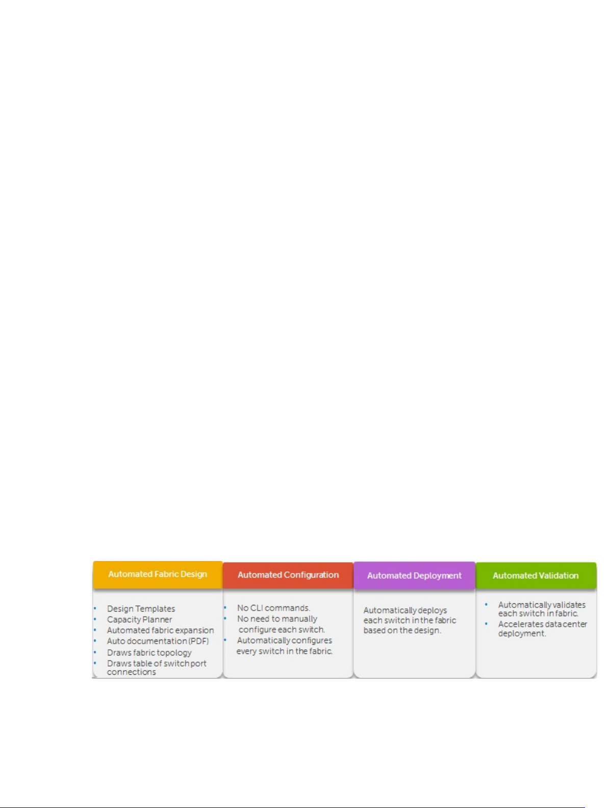
Problem: Challenges to Build a Fabric in the Data Center
• How do you design the fabric?
• What kind of switch do you buy?
• Who is going to use Visio® to manually document the fabric, that is, manually document which switch ports connect
to another switch
• Who is going to draw the cables?
• How will I ensure that this fabric design is accurate?
• Who is going to update the fabric design as I change it or expand it?
• Who is going to configure every switch in the fabric and what kind of errors can happen because this is manually
performed?
• How do I keep track of software versions on each switch?
• Who is going to validate every switch in the fabric to verify that they have the correct version of software and
configuration and that the switches are physically connected to the right switches.
Solution: Active Fabric Manager
9
Page 10

10
Page 11
2
About AFM
Active Fabric Manager (AFM) is a graphical user interface (GUI) based network automation and orchestration tool that
allows you to design, build, deploy, and optimize a Layer 3 distributed core, Layer 3 with Resiliency (Routed VLT), and
Layer 2 VLT fabric for your current and future capacity requirements. This tool helps you simplify network operations,
automate tasks, and improve efficiency in the data center.
NOTE: Before you begin, review the Getting Started page. For information about the AFM workflow, see Flowchart
for Designing and Deploying a Fabric. To learn how to install the AFM, including instructions on completing the
Initial Setup, see the
• Getting Started
• Fabric Designer Wizard
• Pre-deployment Wizard
• Deploying the Fabric
• Alerts
• Administration
• Performance Management
Active Fabric Manager Installation Guide
.
11
Page 12

12
Page 13
Getting Started
This section contains the following topics:
• Designing and Deploying the Fabric
• Flowchart for Designing and Deploying a Fabric
Related links:
• Supported Fabrics
• Designing the Fabric
• AFM Site Map
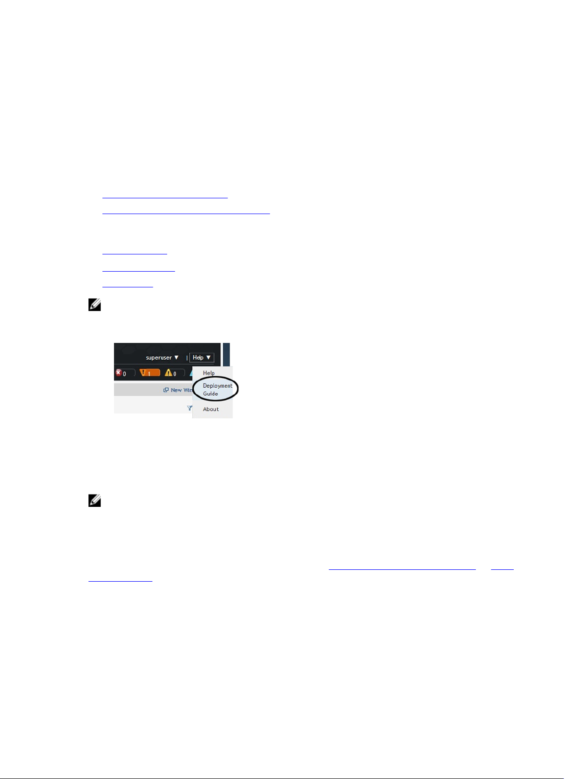
NOTE:
You can view the
from the Help pull-down menu in the upper right of the screen.
Active Fabric Manager Deployment Guide
3
in the AFM by selecting the Deployment Guide option
Designing and Deploying a Fabric
This section provides an overview of the steps required to design and deploy a fabric, including the information you
need before you begin.
NOTE: If you are using the OpenStack Neutron Managed option, refer to the
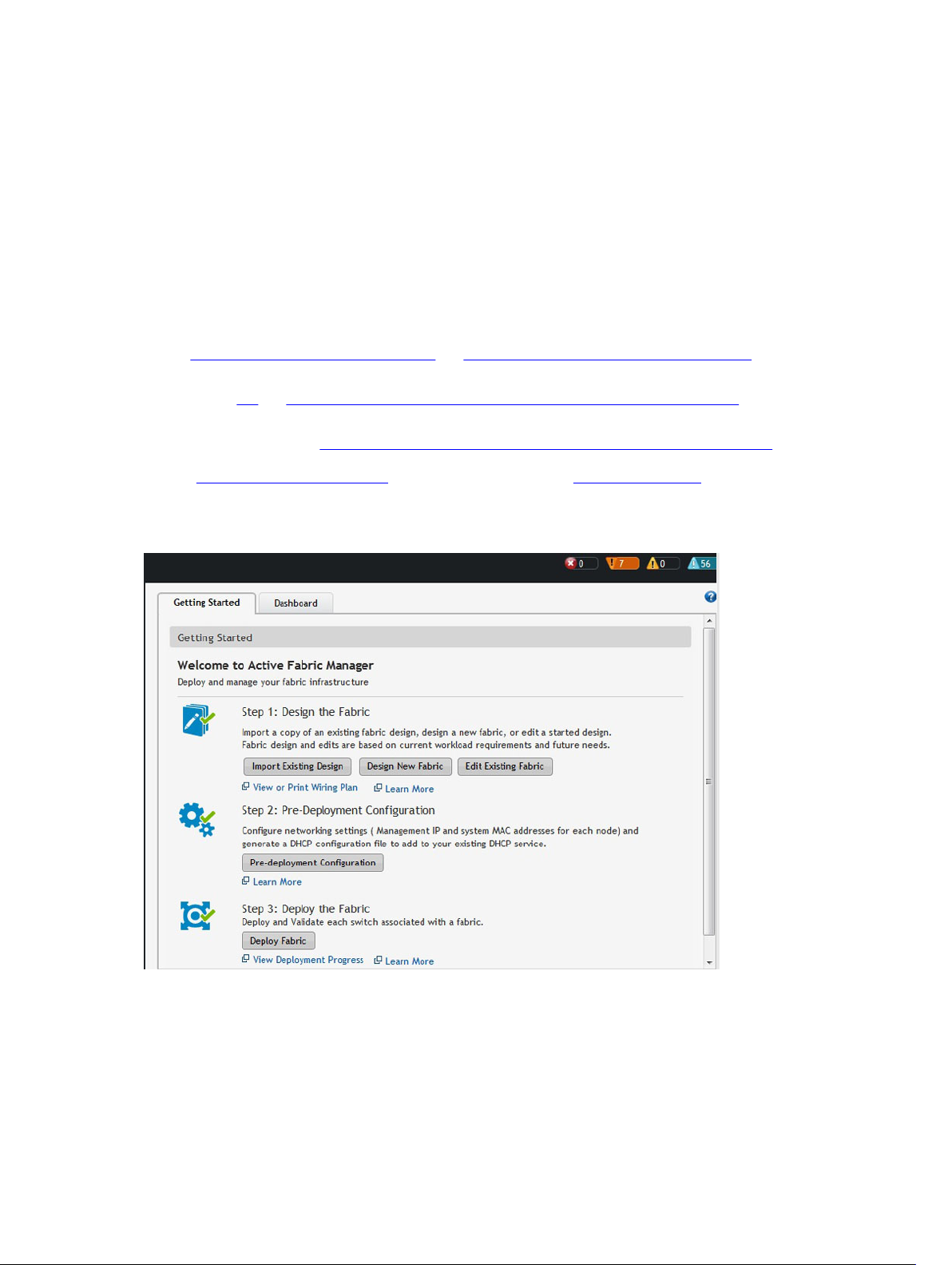
After you complete the basic installation of the Active Fabric Manager (AFM), you must configure it. This is done using
the Getting Started configuration wizard at the Home > Getting Started screen. After you complete the installation
process, the AFM automatically launches this wizard. The Getting Started configuration wizard provides launch points
for designing, pre-deploying, and deploying the fabric. Review the steps in the wizard and the online help or (
Deployment Guide
an existing design.
) before you begin. With this wizard, you can also edit and expand an existing fabric design and import
AFM Plug-in for Openstack Guid
AFM
e.
13
Page 14
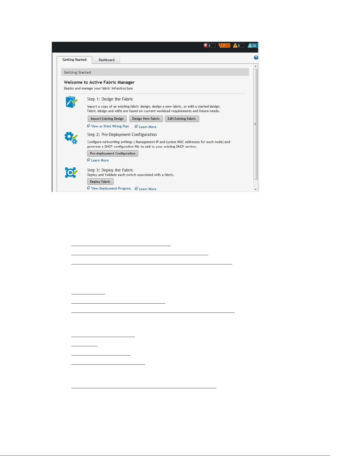
Figure 1. Getting Started Wizard
To design and deploy a Layer 2 VLT, Layer 3 distributed core fabric, or Layer 3 with Resiliency (Routed VLT)
1. Gather useful information.
Related links.
– Gather Useful Information for Layer 2 VLT Fabric
– Gathering Useful Information for a Layer 3 Distributed Core Fabric.
– Gathering Useful Information for a Layer 3 with Resiliency (Routed VLT) Fabric
2. Design the fabric.
Related links designing a Layer 2 VLT fabric:
– Overview of VLT
– Key Considerations fo Designing a VLT Fabric
– Selecting a Layer 2 VLT and Layer 3 with Resiliency (Routed VLT) Fabric Design
Related links for designing a Layer 3 distributed core fabric:
– Overview of a Distributed Core
– Terminology
– Designing a Distributed Core
– Selecting a Distributed Core Design
Related links for designing a Layer 3 with Resiliency (Routed VLT):
– Key Considerations for Designing Layer 3 with Resiliency (Routed VLT)
14
Page 15
– Selecting a Layer 2 VLT and Layer 3 with Resiliency (Routed VLT) Fabric Design
3. Build the physical network.
4. Configure the following settings:
– TFTP/FTP
– SNMP
– CLI Credentials
5. Prepare the Fabric for Deployment
6. Deploy and Validate the Fabric
7. Validate the deployed fabric against the fabric design.
8. Monitor the fabric health and performance. See Performance Management.
NOTE: To provision the fabric, enter the Dell Networking operating system (FTOS) CLI user’s Credentials and
enable the configuration credential for all the switches in the fabric. For information about this topic, see CLI
Credentials.
CAUTION: If you are using a switch that has already been deployed, reset its factory settings in the fabric. The
switch must be in Bare Metal Provision (BMP) mode.
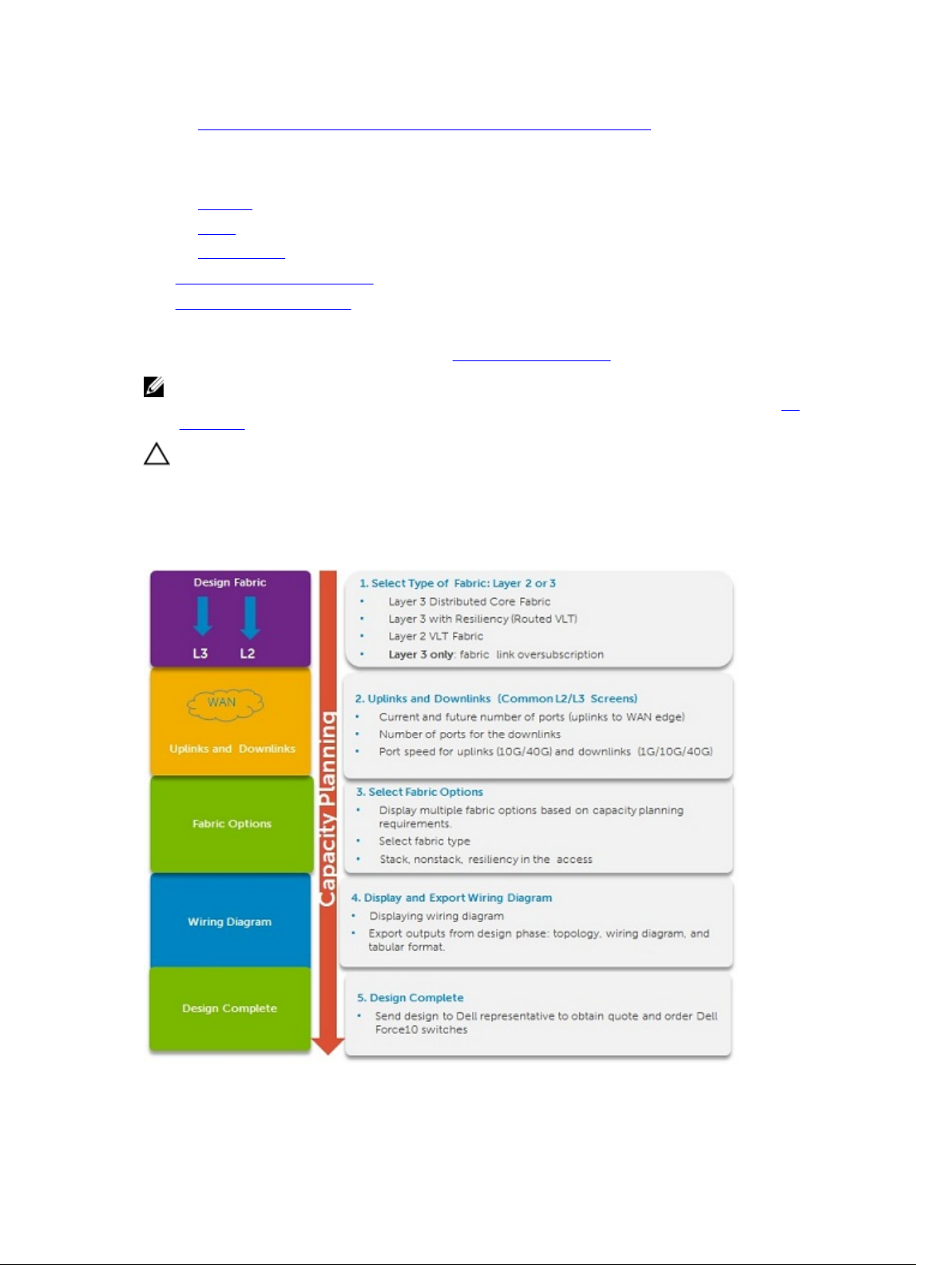
Designing and Deploying a Fabric Flowchart
The following flowchart shows how to design and deploy a new fabric.
Figure 2. Capacity Planning
15
Page 16

Figure 3. Provisioning
16
Page 17
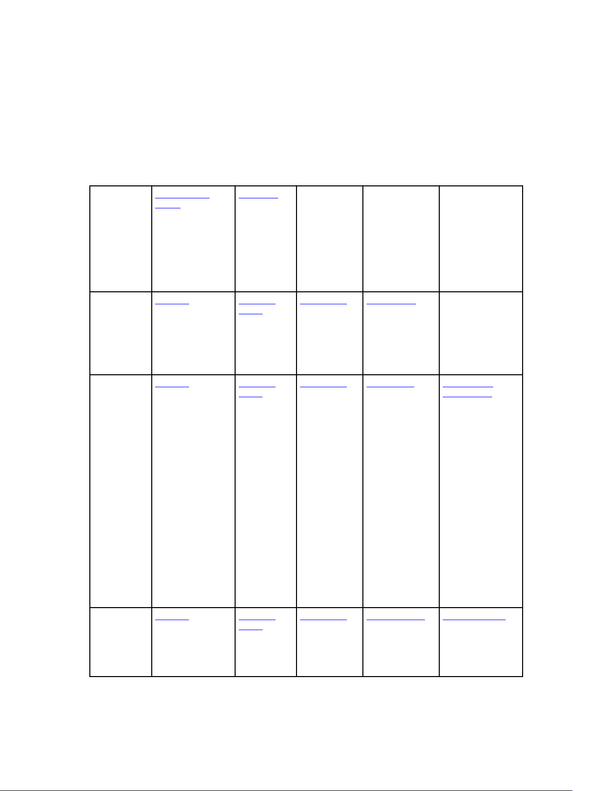
AFM Site Map
To help you navigate the AFM user interface use the following site map.
4
Home Getting Started
Wizard
Step 1: Design the
Fabric
Step 2: PreDeployment
Configuration
Step 3: Deploy the
Fabric
Network
Level
Fabric
Level
Switch
Level
Summary
Map
Network View
Graphical and
Tabular View
Summary
Fabric View
Summary
Device View
Graphical and
Tabular View
Dashboard
Alerts and
Events
Current
Historical
Alerts and
Events
Current
Historical
Alerts and
Events
Current
Historical
Performance
Average
Bandwidth
Utilization
Link Usage
Switch
Statistics
Performance
Average
Bandwidth
Utilization
Link Usage
Switch
Statistics
Performance
Switch and Port
Real-time and
Historical data
Design Fabric
New Fabric
Edit Fabric
Delete Fabric
View Wiring Plan
Maintenance
Software Updates
Backup and
Restore
Troubleshooting
Ping
SSH
Traceroute
Telnet
Configure and
Deploy Fabric
Deploy Fabric
Pre-deployment
Configuration
Deploy and Validate
View DHCP
Configuration
Errors
CLI Configuration
View DHCP
configuration files
Manage Templates
Associate Templates
Custom
Configuration
View Custom
Configuration History
View Wiring Plan
Replace a Switch
Decommission
Switch
Replace Switch
Deploy Switch
17
Page 18
Jobs Job Results Schedule Jobs
Backup
Switch
Configuration
Files
Update switch
software
Active
Software
Administration Audit Log Administration
Active Link
Settings
CLI
Credentials
Client Settings
Data Retention
Settings
DHCP Server
Settings
NTP Server
Settings
Email Settings
Syslog IP
Addresses
SNMP
Configuration
System
Information
TFTP/FTP
Settings
Data Collection
Schedule data
collection
Edit threshold
User Accounts
Add User
Delete User
Edit User
Unlocking User
Reports
Create
Edit
Delete
Duplicate
Run
User Sessions
Display active
AFM users
Terminate users’
sessions
AFM Server Upgrade
AFM Server Upgrade
AFM Server Backup
18
Page 19
5
Supported Fabric Types
The fabric design wizard defines the basic configuration for a Layer 2 VLT, Layer 3 distributed core, and Layer 3 with
Resiliency (Routed VLT) fabric.
• Use the Layer 3 distributed core fabric for large fabric deployments. For information about distributed core fabrics,
see Conventional Core Versus Distributed Core and Selecting a Layer 3 Distributed Core Fabric Design.
• Use the Layer 2 VLT fabric for workload migration over virtualized environments. For information about Layer 2
fabrics, see VLT and Selecting a Layer 2 VLT and Layer 3 with Resiliency (Routed VLT) Fabric Design.
• Use the Layer 3 with Resiliency (Routed VLT) fabric to extend equal cost multi-pathing capabilities. For information
about supported tiers, see Selecting a Layer 2 VLT and Layer 3 with Resiliency (Routed VLT) Fabric Design.
See also Deployment Topology Use Cases. For information about tiers, see Deployment Topology.
To design a fabric based on the capacity requirements for your current and future needs, use the fabric design wizard at
the Network > Configure Fabric > Design New Fabric screen. When you first start AFM, it starts the Getting Started
configuration wizard in the Welcome to Active Fabric Manager screen.
Figure 4. Getting Started: Welcome to Active Fabric Manager Screen
19
Page 20

Key Considerations for Designing a Layer 3 with Resiliency (Routed VLT) Fabric
Use the Layer 3 with Resiliency (Routed VLT) fabric to extend equal cost multi-pathing capabilities. When designing a
Layer 3 with Resiliency (Routed VLT) fabric, consider the following:
• You can deploy up to 10 fabrics. However, the fabrics do not communicate with each other.
• AFM manages Dell Networking S4810, S4820T, S6000, and Z9000 switches.
CAUTION: If you are already using a deployed switch, you must reset the factory settings. The switch must be in
BMP mode.
For more information on BMP, see DHCP Integration and the
S4820T, S6000, and Z9000 switches at https://www.force10networks.com/CSPortal20/KnowledgeBase/
Documentation.aspx.
The number and type of switches in a Layer 3 with Resiliency (Routed VLT) fabric are based on the following:
• The number of current uplinks (minimum of 2) and downlinks for the access switches.
• The number of planned edge ports (future uplinks and downlinks) for the access switches.
• Whether the access switches need to act as a ToR or access.
• Fabric interlink bandwidth (the links between the aggregation and access switches).
• Downlinks which can be 1Gb, 10Gb, or 40 Gb.
• The fabric interlink bandwidth, 10 Gb or 40 Gb, is fixed and based on the fabric type.
CAUTION: If you do not specify additional links in the fabric design for future expansion in the Bandwidth and Port
Count screen you can only expand the downlinks on the existing fabric.
For information on how to expand a fabric, see Editing and Expanding an Existing Fabric Design. For information about
tiers, see Deployment Topology See also Deployment Topology Use Cases.
FTOS Configuration Guide
for the Dell Networking S4810,
Gathering Useful Information for a Layer 3 with Resiliency (Routed VLT) Fabric
To gather useful information for a Layer 3 with Resiliency (Routed VLT) fabric before you begin:
• Obtain the CSV file that contains the system MAC addresses, service tag and serial numbers for each switch
provided from Dell manufacturing or manually enter this information.
• Obtain the location of the switches, including the rack and row number from your network administrator or network
operator.
• Obtain the remote Trivial File Transfer Protocol (TFTP) / File Transfer Protocol (FTP) address from your network
administrator or network operator. To specify a TFTP/FTP site, go to Administration > Settings >TFTP/FTP screen. For
information about which software packages to use, see the Release Notes.
• Download the software image for each type of switch in the fabric. Each type of switch must use the same version of
the software image within the fabric. Place the software images on the TFTP/FTP site so that the switches can
install the appropriate FTOS software image and configuration file.
• Obtain the Dynamic Host Configuration Protocol (DHCP) server address to use for the fabric from your DHCP
network administrator or network operator. If a remote DHCP server is not available, AFM also provides a local
DHCP. The DHCP server must be in the same subnet where the switches are located. After you power cycle the
20
Page 21
switches, the switches communicate with the DHCP server to obtain a management IP Address based on the system
MAC Address. The DHCP server contains information about where to load the correct software image configuration
file for each type of switch from the TFTP/FTP site during BMP. For information about BMP, see DHCP Integration.
• Obtain the pool of IP addresses for the management port for each switch in the fabric.
• Obtain IP addresses (must be an even number) for the uplink configuration from the ISP service. The uplink port
number range is based on whether a 10 Gb or 40 Gb bandwidth is selected.
– For 10 Gb uplink bandwidth, AFM supports 2 to 32 uplinks.
– For 40 Gb uplink bandwidth, AFM supports 2 to 8 uplinks.
• Obtain IP addresses or VLAN ID for the downlink configuration for connecting to the server or ToR.
• Gather protocol configuration for uplinks and downlinks.
Conventional Core Versus Distributed Core
This section describes the differences between a conventional core and a distributed core.
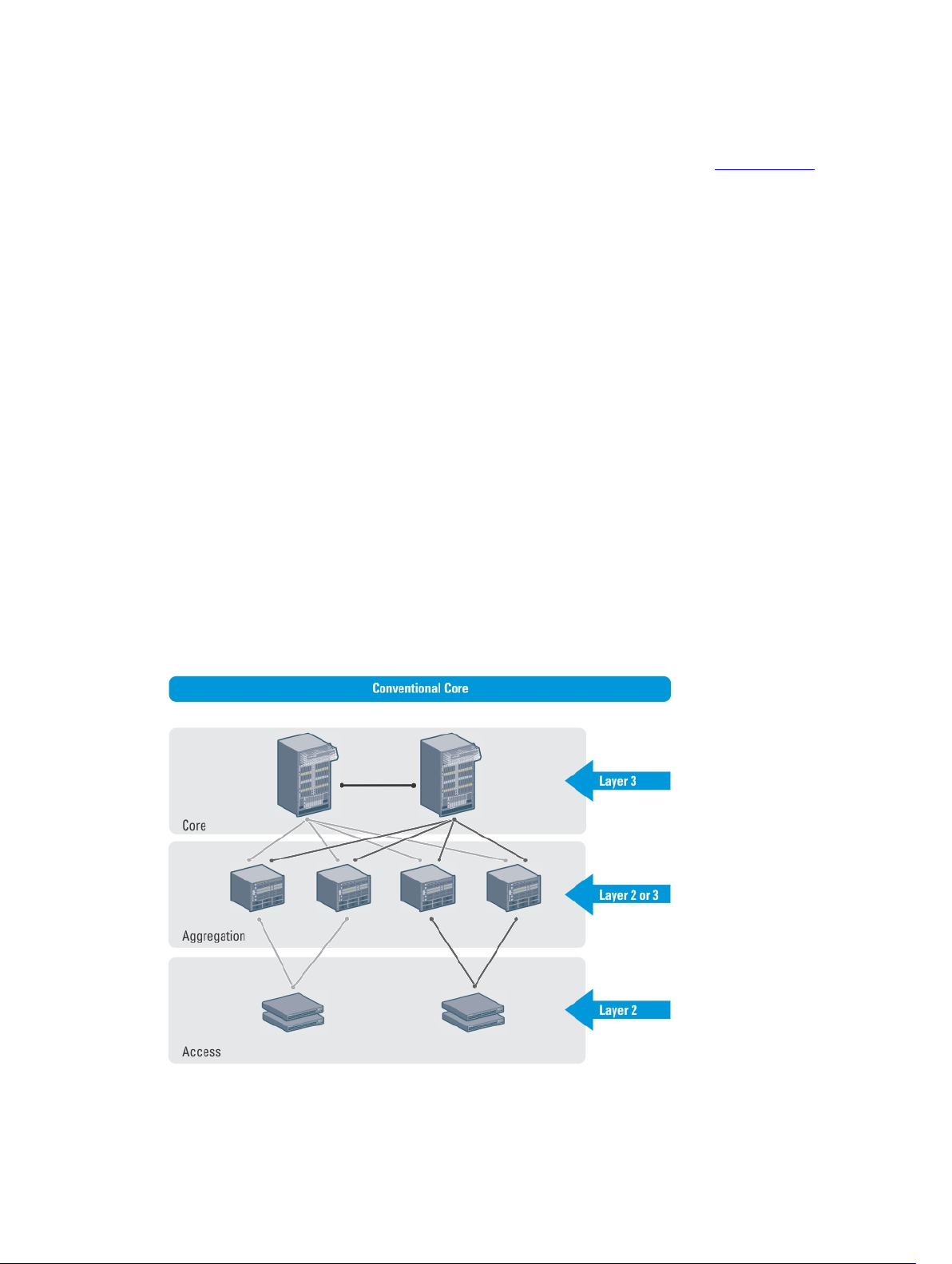
Conventional Core
A conventional core is a three-tier network that is typically chassis based and is composed of the following:
• Core — The core layer routes traffic to and from the internet and the extranet. Redundancy and resiliency are the
main factors for high availability, which requires chassis-based core routers.
• Aggregation layer — The aggregation layer connects with top of rack (ToR) switches and aggregates the traffic into
fewer high-density interfaces such as 10GbE or 40GbE. This layer aggregates the traffic to the core layer.
• Access layer (ToR) — The access layer typically contains ToRs. A ToR is a small form-factor switch that sits on top
of the rack and allows all the servers in the rack to be cabled into the switch. A ToR has a small 1 to 2 rack unit (RU)
form factor.
21
Page 22

Distributed Core
A distributed core is a two-tier architecture composed of multiple switches interconnected to provide a scalable, highperformance network that replaces the traditional and aggregation layers in a conventional core. Switches are arranged
as spines and leaves; the spines fabric connect the leaves together using a routing protocol. The leaves’ edge ports
connect to the switches, ToR switches, servers, other devices, and the WAN. The spines move traffic between the
leaves bi-directionally, providing redundancy and load balancing. Together, the spine and leaf architecture forms the
distribute core fabric.
This two-tier network design allows traffic to move more efficiently in the core at a higher bandwidth with lower
latencies than most traditional three-tier networks. Because there is no single point of failure that can disrupt the entire
fabric, the distributed core architecture is more resilient and as a result, there is less negative impact on the network
when there is a link or node failure. The AFM views the distributed core as one logical switch.
NOTE: There are no uplinks on the spines. All the leaves have downlinks. The uplink should be configured in the
first two leaves.
Key Advantages
The key advantages of a distributed core architecture are:
• Simplified fabric
• Higher bandwidth
• Highly resilient
• Higher availability
• Low power consumption
• Less cooling
• Lower latency
• Lower cost
• Less rack space
• Easier to scale
22
Page 23

Distributed Core Terminology
The following terms are unique to the design and deployment of a Layer 3 distributed core fabric.
• Leaf — A switch that connects switches, servers, storage devices, or top-of-rack (TOR) elements. The role of the
leaves switches is to provide access to the fabric. The leaf switch connects to all of spines above it in the fabric.
• Spine — A switch that connects to the leaves switches. The role of the spine is to provide an interconnect to all the
leaves switches. All the ports on the spine switches are used to connect the leaves, various racks together. The
spines provides load balancing and redundancy in the distributed core. There are no uplinks on the spines.
• Edge ports — The uplinks and downlinks on the leaves.
• Uplinks — An edge port link on the first two leaves in the distributed core fabric that connects to the edge WAN,
which typically connects to an internet server provider (ISP).
• Downlinks — An edge port link that connects the leaves to the data access layer; for example, servers or ToR
elements.
NOTE: Specify an even number of uplinks. The minimum number of uplinks is 2. One uplink is for redundancy.
• Fabric Interlinks — Links that connect the spines to the leaves. The fabric interlink bandwidth is fixed: 10 Gb or 40
Gb.
• Fabric over-subscription ratio — Varies the maximum number of available interconnect links. This ratio determines
the number of fabric interlinks (the number of communication links between the spine and leaf devices). The ratio
that you specify depends on the bandwidth, throughput, and edge port requirements. The interlink overoversubscription ratio does not come off the edge port downlinks.
As you increase the fabric over-subscription ratio:
– The total number of ports for the downlinks increases.
– The number of interconnect links from the leaves to the spines decreases.
– The maximum number of available ports increases.
For non-blocking (line rate) between the leaves and spines, select the 1:1 fabric over-subscription ratio. This ratio is
useful when you require a lot of bandwidth and not a lot of ports.
The following image illustrates a distributed core fabric.
23
Page 24
Important: In a single distributed fabric, all the leaves can act as a non-ToR or as a ToR, not both at the same
time.
Key Considerations for Designing a Distributed Core
When designing the Layer 3 distributed core fabric, consider the following:
• You can deploy up to 10 fabrics. However, the fabrics do not communicate with each other.
• AFM manages Dell S4810, S4820T, S6000, and Z9000 switches.
CAUTION: If you are already using a deployed switch, reset the factory settings. The switch must be in BMP mode.
For information on BMP, see DHCP Integration and the
Z9000 switches at https://www.force10networks.com/CSPortal20/KnowledgeBase/Documentation.aspx. See also
Deployment Topology Use Cases.
The number and type of spines and leaves (switches) in a distributed core fabric are based on the following:
• The type of distributed core fabric design:
– Type 1: Extra Large Core
– Type 2: Large Core
– Type 3: Medium Core
– Type 4: Small Core
• The number of current uplinks and downlinks for the leaves.
• The number of planned edge ports (future uplinks and downlinks) for the leaves.
• Whether you require non-blocking (line rate) performance.
24
FTOS Configuration Guide
for either the S4810, S4820T, S6000, or
Page 25

• Whether the leaves act as a ToR or are connecting to a server.
• Fabric interlink bandwidth (the links between the spines and leaves).
• Uplinks which are 10 Gb.
• Downlinks which are 1 Gb, 10 Gb, or 40 Gb.
• When the Open Shortest Path First (OSPF) is selected for both uplinks and interlinks, one of the uplinks or interlinks
must be in area 0. If one uplink is in area 0 then the interlinks must not be in area 0.
• The fabric over-subscription ratio.
• Fixed fabric interlink bandwidth that is based on the fabric type: 10 Gb or 40 Gb.
Important: If you do not specify additional links in the fabric design for future expansion in the Bandwidth and Port
Count screen, you can only expand the downlinks on the existing fabric.
For information about how to expand a fabric, see Editing and Expanding an Existing Fabric Design.
Gathering Useful Information for a Distributed Core
To gather the following useful information for a Layer 3 distributed core fabric before you begin:
• Obtain the comma-separated values (CSV) file that contains the system media access control (MAC) addresses,
service tag, and serial numbers for each switch provided from Dell manufacturing or manually enter this information.
• Obtain the location of the switches, including the rack and row number from your network administrator or network
operator.
• Obtain the Remote Trivial File Transfer Protocol (TFTP) or File Transfer Protocol (FTP) address from your network
administrator or network operator. To specify a TFTP/FTP site, go to Administration > Settings > TFTP/FTP screen.
For information about which software packages to use, see the Release Notes.
• Download the software image for each type of switch in the fabric. Each type of switch must use the same version of
the software image within the fabric. Place the software images on the TFTP or FTP site so that the switches can
install the appropriate FTOS software image and configuration file.
• Obtain the Dynamic Host Configuration Protocol (DHCP) server address to be used for the fabric from your DHCP
network administrator or network operator. If a remote DHCP server is not available, AFM also provides a local
DHCP server. The DHCP server must be in the same subnet where the switches are located. After you power cycle
the switches, the switches communicate with the DHCP server to obtain a management IP address based on the
system MAC address. The DHCP server contains information about where to load the correct software image
configuration file for each type of switch from the TFTP/FTP site during BMP. For information about BMP, see DHCP
Integration.
• Obtain pool of IP addresses for the management port for each switch in the fabric.
• Obtain IP addresses (must be an even number) for the uplink configuration from the ISP service. The uplink port
number range is based on whether a 10 Gb or 40 Gb bandwidth is selected.
– For a 10 Gb bandwidth, AFM supports 2 to 32 uplinks.
– For a 40 Gb bandwidth, AFM supports 2 to 8 uplinks.
• Obtain IP addresses for the downlink configuration for connecting to the server or ToR.
• Obtain IP addresses for the fabric link configuration for the spine and leaf switches.
• Gather protocol configuration for uplinks, downlinks and fabric link configuration
25
Page 26

Selecting a Layer 3 Distributed Core Fabric Design
For large fabric deployments, use the Layer 3 distributed core fabric. AFM supports the following distributed core fabric
designs:
• Type 1: Extra Large Core Fabric
• Type 2: Large Distributed Core Fabric
• Type 3: Medium Distributed Core Fabric
• Type 4: Small Distributed Core Fabric
To select the appropriate Layer 3 distributed core fabric design, use the following table as a guide. For more information
about a Layer 3 distributed core, see:
• Overview of a Distributed Core
• Key Considerations for Designing a Distributed Core Fabric
• Flowchart for Designing and Deploying a Fabric.
With a Layer 3 distributed core topology, you select the Layer 3 option using the Design Wizard on the Deployment
Topology screen. For information about distributed core, see Selecting a Distributed Core Design.
DL BW — Downlink Bandwidth
UL BW — Uplink Bandwidth
Attention: The maximum number of downlinks is based on using 2 uplinks.
Table 1. 2 Tier Layer 3 Distributed Core Topologies
Type OS
Ratio
Type 1-Extra Large
Core
Type 2-Large Core
Type 3-Medium
Core
Type 3-Medium
Core
Type 4-Small Core
Type 4-Small Core
1:1 10G 2046 16
1:1 10G 2046 32
3:1 10G 766 4
4:1 10G 1662 3
5:1 10G 894 2
3:1 10G 1534 4
DL
BW
Maximum #
of
Downlink
Maximum #
of Spine
Devices
Maximum
# of Leaf
Devices
32
64
32
32
8
16
UL BWFabric Link
Bandwidth
Between
the Spine
and Leaf
10G 40G Z9000/Z9000 or
10G 10G S4810/S4810
10G 10G S4810/S4810
10G 40G Z9000/S4810 or
10G 10G S4810/S4810
10G 40G Z9000/S4810 or
Possible
Topologies (Spine
and Leaf)
S6000/S6000
S6000/S4810
S6000/S4810
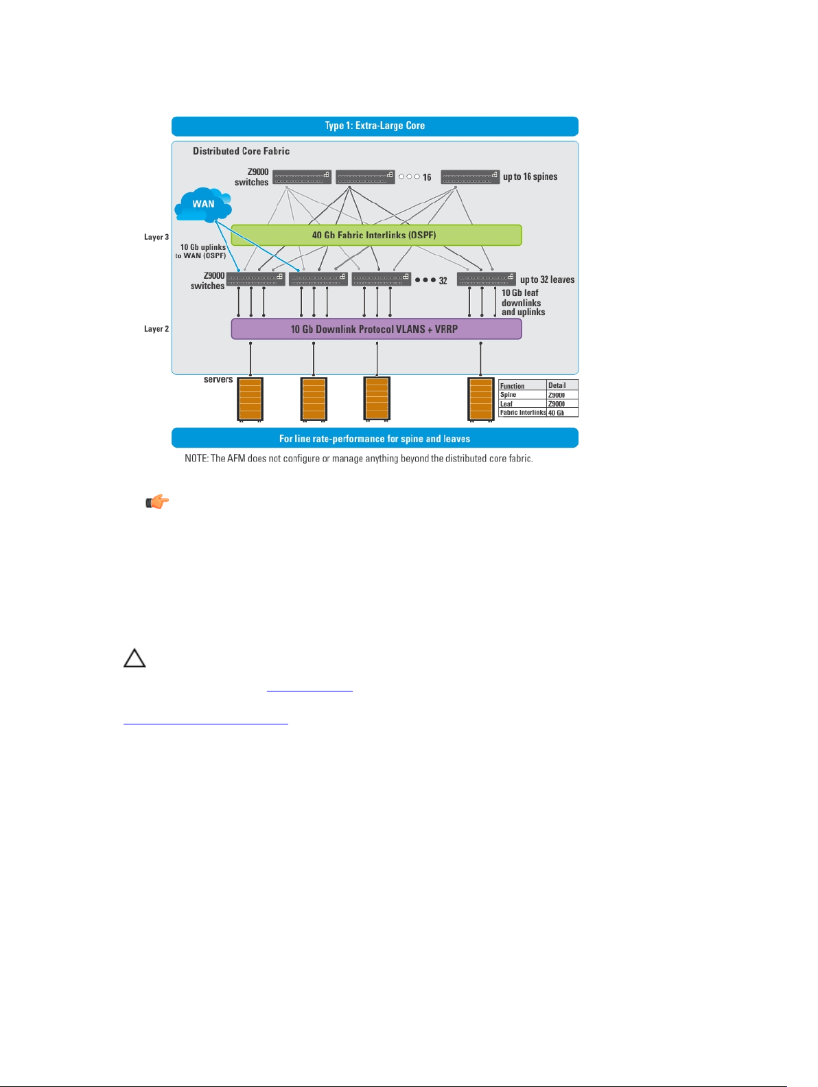
Type 1: Extra Large Distributed Core Fabric
With a Type 1: Extra Large Distributed Core fabric design, the Z9000 spines (or S6000 spines) connect to the Z9000 leaves
(S6000 leaves) at a fixed 40 Gb line rate. The maximum number of leaves is based on the maximum number of ports on
the spine, 32 ports for the Z9000, as shown in the following figure.
26
Page 27
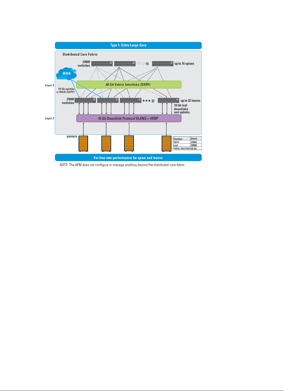
Figure 5. Type 1: Extra Large Distributed Core Fabric Design
Use the Type 1: Extra Large Distributed Core fabric design when:
• The line rate-performance with a fabric oversubscription ratio of 1:1 between the spines and leaves.
• The current and future planned uplinks and downlinks on the leaves for the distributed core is less than or equal to
2048 ports.
For redundancy, each leaf in a large core design can connect 2 to 16 spines. The Type 1: Extra Large Distributed Core
Design uses a 1:1 spine-to-leaf ratio. As a result, the maximum number of spines for this design is 16 and the maximum
number of leaves is 32.
Each Z9000 or S6000 leaf for the Type 1: Extra Large Distributed Core design has the following:
• Six hundred forty Gigabit of fabric interlink (fabric links) maximum capacity to the Spine (16 x 40 Gb)
• Forty-eight 10 Gb ports for server connectivity and WAN connectivity
Type 2: Large Distributed Core Fabric
Use the Type 2: Large Distributed Core fabric design when:
• You require a fabric interlink (fabric links) bandwidth between the spines and leaves of 10 Gb is required.
• The current and future planned uplinks and downlinks on the leaves for the fabric is less than or equal to 2048 ports.
• The leaves act as a switch or ToR-leaf switch. Within the ToR, the downlink protocol can be either VLAN or VLAN
and LAG.
With a Type 2: Large Distributed Core fabric design, the S4810 spines connect to the S4810 leaves at a fixed 10 Gb. The
maximum number of spines is 32 and the maximum number of leaves is 64, as shown in the following figure.
27
Page 28
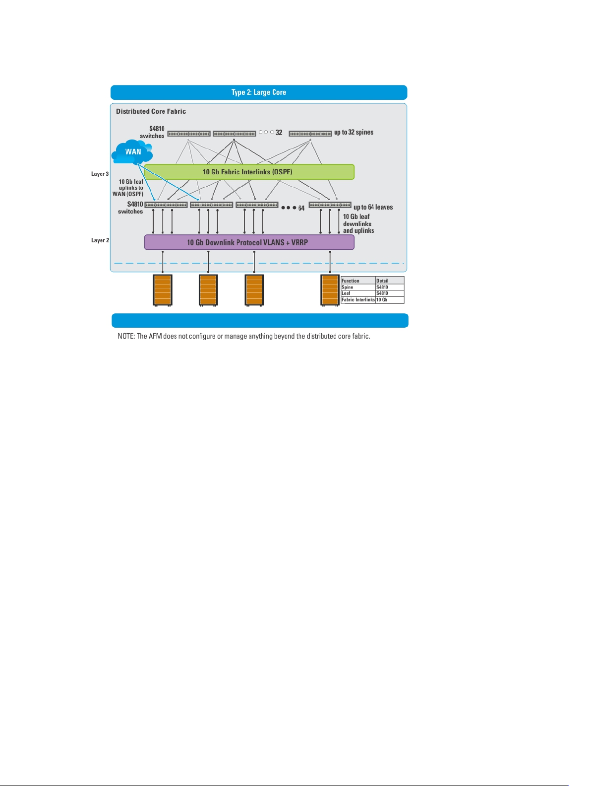
Figure 6. Type 2: Large Distributed Core Fabric Design
Each S4810 leaf for the Type 2: Large Distributed Core fabric design has the following:
• Forty gigabit of fabric interlink (fabric links) maximum capacity to the spine (4x 10 Gb)
• Thirty-two 10 Gigabit ports will be used for fabric interlink (fabric links) and thirty–two 10 Gb ports are used for the
downlinks
Type 3: Medium Distributed Core Fabric
With a Type 3: Medium Distributed Core design, the Z9000 spines (S6000 spines) connect to the S4810 leaves at a fixed
40 Gb line rate as shown in the following figure. The maximum number of leaves is based on the maximum number of
ports on the spine, 32 ports for the Z9000. The maximum number of spines is 16 and the maximum number of leaves is 32,
as shown in the following illustration. This illustration shows a networking system architecture in a data center are a
distributed core fabric containing a set of ToRs to which servers, storage devices, and network appliances (such as load
balancers or network security appliances) are connected. You can run application services, network services, and
network security services either on physical machines or virtual machines.
28
Page 29
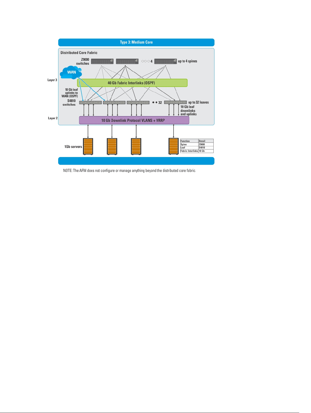
Figure 7. Type 3: Medium Distributed Core Fabric Design
Use the Type 3: Medium Distributed Core design when:
• You require a fabric interlink (fabric links) bandwidth between the spines and leaves at a 40 Gb line rate.
• The current and future planned uplinks and downlinks on the leaves for your distributed core fabric is less than or
equal to 1536 ports.
• The leaves act as a switch or ToR-leaf switch. Within the ToR, the protocol can be either VLAN or VLAN and LAG.
Each Z9000 spine (S6000 spine) for the Type 3: Medium Distributed Core design has the following:
• Six hundred and forty Gigabit of interlink (fabric links) maximum capacity to the spine (16 x 40 Gig)
• Six hundred and forty 10 Gig Ethernet ports for WAN connectivity
Each S4810 leaf for the Type 3: Medium Distributed Core design has the following:
• One hundred and sixty Gigabit of interlink (fabric links) maximum capacity to the spine (4x 40 Gig)
• Forty–eight 10 Gig Ethernet ports for WAN connectivity
Type 4: Small Distributed Core Fabric
Use the Type 4: Small Distributed Core design when:
• You require a fabric interlink (fabric links) bandwidth between the spines and leaves of 10 Gb.
• The current and future planned uplinks and downlinks on the leaves for your core is less than or equal to 960 ports.
• The maximum port count for a Type 4: Small Distributed Core fabric with an OS ratio of 3:1 is 768. For an OS ratio of
5:1, the maximum port count is 896.
• The leaves act as a switch or ToR-leaf switch. Within the ToR, the downlink protocol can be either VLAN or VLAN
and LAG.
29
Page 30
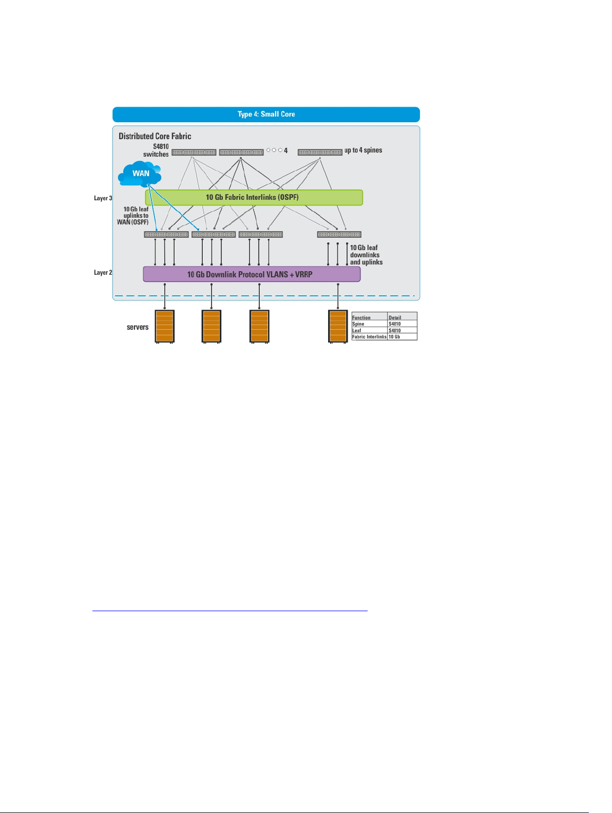
With a Type 4: Small Distributed Core fabric design, the S4810 spines connect to the S4810 leaves at a fixed 10 Gb. The
maximum number of spines is 4 and the maximum number of leaves is 16, as show in the following figure.
Figure 8. Type 4: Small Distributed Core Fabric Design
Each S4810 leaf for the Type 4: Small Distributed Core design has the following:
• Sixteen 10 Gigabit of fabric interlink (fabric links) port capacity to the spine
• Forty–eight 10 Gig Ethernet downlinks
• Sixty 10 Gig Ethernet ports for servers per node and WAN connectivity
VLT
Virtual link trunking (VLT) allows physical links between two chassis to appear as a single virtual link to the network core
or other switches such as Edge, Access or Top of Rack (ToR). VLT reduces the role of Spanning Tree protocols by
allowing LAG terminations on two separate distribution or core switches, and by supporting a loop free topology. (A
Spanning Tree protocol is needed to prevent the initial loop that may occur prior to VLT being established. After VLT is
established, RSTP may be used to prevent loops from forming with new links that are incorrectly connected and outside
the VLT domain.) VLT provides Layer 2 multipathing, creating redundancy through increased bandwidth, enabling
multiple parallel paths between nodes and load-balancing traffic where alternative paths exist.
For information about VLT, see the FTOS Configuration Guide for either the S4810, S6000, or the Z9000 at https://
www.force10networks.com/CSPortal20/KnowledgeBase/Documentation.aspx. For more information about VLT, see
Selecting a Layer 2 and Layer 3 with Resiliency (Routed VLT) Fabric Design.
Virtual link trunking offers the following benefits:
• Allows a single device to use a LAG across two upstream devices
• Eliminates Spanning Tree protocol (STP) - blocked ports
• Provides a loop-free topology
• Uses all available uplink bandwidth
30
Page 31

• Provides fast convergence if either the link or a device fails
• Optimized forwarding with Virtual Router Redundancy Protocol (VRRP)
• Provides link-level resiliency
• Assures high availability
CAUTION:
Dell Networking recommends not enabling stacking and VLT simultaneously.
If both are enabled at the same time, unexpected behavior occurs.
Multi-domain VLT
An multi-domain VLT (mVLT) configuration allows two different VLT domains connected by a standard Link Aggregation
Control protocol (LACP) LAG to form a loop-free Layer 2 topology in the aggregation layer. This configuration supports a
maximum of 4 units, increasing the number of available ports and allowing for dual redundancy of the VLT. For more
information about mVLT deployments, see Selecting a Layer 2 VLT and Layer 3 with Resiliency (Routed VLT) Fabric
Design.
VLT Terminology
The following are key VLT terms.
• Virtual link trunk (VLT) — The combined port channel between an attached device and the VLT peer switches.
• VLT backup link — The backup link monitors the health of VLT peer switches. The backup link sends configurable,
periodic keep alive messages between VLT peer switches.
• VLT interconnect (VLTi) — The link used to synchronize states between the VLT peer switches. Both ends must be
on 10 Gb or 40 Gb interfaces.
• VLT domain — This domain includes both VLT peer devices, the VLT interconnect, and all of the port channels in the
VLT connected to the attached devices. It is also associated to the configuration mode that must be used to assign
VLT global parameters.
• VLT peer device — One of a pair of devices that are connected with the special port channel known as the VLT
interconnect (VLTi).
VLT peer switches have independent management planes. A VLT interconnect between the VLT chassis maintains
synchronization of Layer 2 and Layer 3 control planes across the two VLT peer switches. The VLT interconnect uses
either 10 Gb or 40 Gb ports on the switch.
A separate backup link maintains heartbeat messages across an out-of-band (OOB) management network. The backup
link ensures that node failure conditions are correctly detected and are not confused with failures of the VLT
interconnect. VLT ensures that local traffic on a chassis does not traverse the VLTi and takes the shortest path to the
destination via directly attached links.
VLT Fabric Terminology
The following terms are unique to the design and deployment of a Layer 2 VLT fabric.
• Core — A switch that connects to aggregation switches. The role of the core is to provide an interconnect to all the
aggregation switches. All the ports on the core switch are used to connect the aggregation, various rack together.
• Access — A switch that connects switch, servers, storage devices, or top-of-rack (TOR) elements. The role of the
access switch is to provide connectivity to the fabric. The access switch connects to all of aggregation switches
above it in the fabric.
31
Page 32

• Aggregation — A switch that connects to access switches. The role of the aggregation layer is to provide an
interconnect to all the access switches. All the ports on the aggregation switches are used to connect the access,
various racks together. The aggregation switch provides redundancy.
• Edge ports — The uplinks on the aggregation and downlinks on the access.
• Uplinks — An edge port link on the first two aggregation switches in the VLT fabric that connects to outside the
fabric.
• Downlinks — An edge port link that connects the access switches to the access layer. For example, servers or ToR
elements.
• Fabric Interlinks (Fabric Links) — The fabric interlink bandwidth is fixed: 10 Gb or 40 Gb.
– For a 1-Tier, links that connect a pair of aggregation switches.
– For a 2-Tier, links that connect the aggregation switches to the access switches.
– For a 3-Tier, links that connect the core, aggregation, and access switches together.
VLT Components
Typical VLT Topology
The VLT domain has VLTi (ICL) links connecting between VLT peers and VLT port-channels connecting to a single
access switch, to a switch stack, a server supporting LACP on its NIC, or to another VLT domain as shown in the
following illustration. The backup-link connected through the out-of-band (OOB) management network. Some hosts can
32
Page 33

connect through the non-VLT ports.
Key Considerations for Designing a Layer 2 VLT Fabric
Use the Layer 2 VLT fabric for workload migration over virtualized environments. When designing the Layer 2 VLT fabric,
consider the following:
• You can deploy up to 10 fabrics. However, the fabrics do not communicate with each other.
• For a VLT fabric, the AFM manages Dell Networking S4810, S4820T, S55, S60, S6000, Z9000, and MXL Blade switches.
CAUTION: If you are already using a deployed switch, you must reset the factory settings. The switch must be in
BMP mode.
For more information on BMP, see DHCP Integration and the
S4820T, S55, S60, S6000, Z9000, and MXL switches at https://www.force10networks.com/CSPortal20/KnowledgeBase/
Documentation.aspx.
The number and type of switches in a VLT fabric are based on the following:
• The number of current uplinks (minimum of 2) and downlinks for the access switches.
• The number of planned edge ports (future uplinks and downlinks) for the access switches.
• Whether the access switch needs to act as a switch or ToR.
• Fabric interlink bandwidth (the links between the aggregation and access switches).
• Downlinks which can be 1Gb, 10Gb, or 40 Gb.
• The fabric interlink bandwidth, 10 Gb or 40 Gb, is fixed and based on the fabric type.
NOTE: If you do not specify additional ports in the fabric design for future expansion in the Bandwidth and Port
Count screen, you can only expand the downlinks on the existing fabric.
For information on how to expand a fabric, see Editing and Expanding an Existing Fabric Design.
FTOS Configuration Guide
for the Dell Networking S4810,
33
Page 34

Gathering Useful Information for a Layer 2 VLT Fabric
To gather useful information for a layer 2 VLT fabric before you begin:
• Obtain the CSV file that contains the system MAC addresses, service tag and serial numbers for each switch
provided from Dell manufacturing or manually enter this information.
• Obtain the location of the switches, including the rack and row number from your network administrator or network
operator.
• Obtain the remote Trivial File Transfer Protocol (TFTP) / File Transfer Protocol (FTP) address from your network
administrator or network operator. To specify a TFTP/FTP site, go to Administration > Settings >TFTP/FTP screen. For
information about which software packages to use, see the Release Notes.
• Download the software image for each type of switch in the fabric. Each type of switch must use the same version of
the software image within the fabric. Place the software images on the TFTP/FTP site so that the switches can install
the appropriate FTOS software image and configuration file.
• Obtain the Dynamic Host Configuration Protocol (DHCP) server address to use for the fabric from your DHCP
network administrator or network operator. If a remote DHCP server is not available, AFM also provides a local
DHCP. The DHCP server must be in the same subnet where the switches are located. After you power cycle the
switches, the switches communicate with the DHCP server to obtain a management IP Address based on the system
MAC Address. The DHCP server contains information about where to load the correct software image configuration
file for each type of switch from the TFTP/FTP site during BMP. For information about BMP, see DHCP Integration.
• Obtain the pool of IP addresses for the management port for each switch in the fabric.
• Obtain IP addresses (must be an even number) for the uplink configuration from the ISP service. The uplink port
number range is based on the whether a 10 Gb or 40 Gb bandwidth is selected.
– For a 10 Gb bandwidth, AFM supports 2 to 32 uplinks.
– For a 40 Gb bandwidth, AFM supports 2 to 8 uplinks.
Obtain IP addresses or VLAN ID for the downlink configuration for connecting to the server or ToR.
• Gather protocol configuration for uplinks and downlinks.
Selecting a Layer 2 and Layer 3 with Resiliency (Routed VLT) Fabric Design
For workload migration over virtualized environments, use a Layer 2 VLT fabric design. Use the Layer 3 with Resiliency
(Routed VLT) fabric to extend equal cost multi-pathing capabilities.
The AFM supports the following Layer 2 VLT and Layer with 3 with Resiliency (Routed VLT) fabric designs:
• 1 Tier for 10 Gb and 40 Gb ToR for Layer 2 and Layer 3 Resiliency (Routed VLT)
• 2 Tier and 3 Tier Topologies for 1 Gb ToR VLT Deployment for Layer 2 and Layer 3 with Resiliency (Routed VLT)
• 10 Gb or 40 Gb Top of Rack Deployment (mVLT)
• 2 and 3 Tier 10 Gb ToR (mVLT) Deployment Topologies for Layer 2 or Layer 3 with Resiliency
• 10 Gb Blade Switch (MXL) for Layer 2 and Layer 3 with Resiliency (Routed VLT)
For information about tiers, see Deployment Topology See also Deployment Topology Use Cases.
For more information about VLT, see:
• Overview of VLT
• Key Core Design Considerations for VLT
34
Page 35

• Getting Started.
1 Tier for 10 Gb and 40 Gb ToR for Layer 2 and Layer 3 Resiliency (Routed VLT)
Table 2. 1 Tier for 10 Gb and 40 Gb ToR for Layer 2 and Layer 3 Resiliency (Routed VLT)
Downlink
Bandwidth
10 Gb 10 Gb 1 - 110 2 * 40 Gb NA S4810 or S4820T NA
10 Gb 40 Gb 1 - 104 2 * 40 Gb NA S4810 or S4820T NA
40 Gb 10 Gb 1 - 59 2 * 40 Gb NA Z9000 or S6000 NA
40 Gb 40 Gb 1 - 58 2 * 40 Gb NA Z9000 or S6000 NA
Uplink
Bandwidth
Port Range Aggregation VLTi
Capacity
Possible Topologies
Core Aggregation Access
2 Tier and 3 Tier Topologies for 1 Gb ToR VLT Deployment for Layer 2 and Layer 3 with Resiliency (Routed
VLT)
With a 1 Gb ToR VLT Deployment fabric design, the S4810 aggregation switches connect to access switches at fixed 10
Gb. The maximum number of VLT aggregation is 2 switches and the maximum number of VLT access switches is based
on the number of uplinks and downlinks you design in your fabric. With this topology, the downlinks connect to access
S55 or S60 switches using a 1 Gb bandwidth.
Figure 9. 1 Gb ToR VLT Deployment
Important: All the VLT aggregation switches must be same mode type for aggregation; for example, S4810. On the
VLT access, you must configure the same model type.
AVG = Aggregation VLTi Capacity
DL = Downlink
35
Page 36

DL BW = Down Link Bandwidth
FL BWB A & A = Fabric Link Bandwidth between Aggregation & Access
UL BW = Uplink Bandwidth
BW = Bandwidth
Use the following table as guideline to select the appropriate 2– Tier Layer 2 VLT or Layer 3 with Resiliency (Routed VLT)
fabric design for a 1 Gb ToR VLT deployment.
NOTE: With a Layer 2 VLT fabric, the uplinks come from the first two switches on the aggregation side. For
information about tiers, see Deployment Topology.
Table 3. 2 Tier (1 Gb Downlinks)
DL BWULBW Type DL Port
Range
AVG Access
VLTi
Capacity
FL
BWB A
& A
Possible Topologies
Core Aggregation Access
1 Gb 10 Gb Stacking 1 - 2640 2 * 40 Gb NA 40 Gb NA S4810 S60
(12G or 24G)
1 Gb 10 Gb Stacking 1 - 2640 2 * 40 Gb NA 40 Gb NA S4810 S55 (12G )
1 Gb 40 Gb Stacking 1 - 2496 2 * 40 Gb NA 40 Gb NA S4810 S60
(12G or 24G)
1 Gb 40 Gb Stacking 1 - 2496 2 * 40 Gb NA 40 Gb NA S4810 S55
(12G )
1 Gb 10 Gb Basic 1 - 2640 2 * 40 Gb NA 20 Gb NA S4810 S60
1 Gb 10 Gb Basic 1 - 2640 2 * 40 Gb NA 20 Gb NA S4810 S55
1 Gb 40 Gb Basic 1 - 2496 2 * 40 Gb NA 20 Gb NA S4810 S60
1 Gb 40 Gb Basic 1 - 2496 2 * 40 Gb NA 20 Gb NA S4810 S55
Use the following table as guideline to select the appropriate 3– Tier Layer 2 VLT or Layer 3 with Additional Resiliency
(Routed VLT) fabric design for a 1 Gb ToR VLT deployment.
AVG = Aggregation VLTi Capacity
CVG = Core VLTi Capacity
DL = Downlink
DL BW = Downlink Bandwidth
FL BWB C & A = FL BW between Core & Aggregation
FL BWB A & A = Fabric Link Bandwidth between Aggregation & Access
FL BW = Fabric Link Bandwidth
UL BW = Uplink Bandwidth
BW = Bandwidth
Table 4. 3 Tier ToR (1 Gb Downlinks) for Layer 2 and Layer 3 with Resiliency (Routed VLT)
DL BWUL BWType DL Port
Range
1 Gb 10 Gb Stacking 2641 -
32256
36
CVG AVG Access
VLTi
Capacity
FL
BWB
C & A
FL
BWB
A & A
Possible Topologies
Core Aggregation Access
2 * 40 Gb2 * 40 GbNA 80G 40 Gb Z9000 S4810 S55 (12G )
Page 37

1 Gb 10 Gb Stacking 2641 -
32256
1 Gb 40 Gb Stacking 2497 -
32256
1 Gb 40 Gb Stacking 2497 -
32256
1 Gb 10 Gb Basic 2641 -
32256
1 Gb 10 Gb Basic 2641 -
32256
1 Gb 40 Gb Basic 2497 -
32256
1 Gb 40 Gb Basic 2497 -
32256
or
S6000
2 * 40 Gb2 * 40 GbNA 80G 40 Gb Z9000
or
S6000
2 * 40 Gb2 * 40 GbNA 80G 40 Gb Z9000
or
S6000
2 * 40 Gb2 * 40 GbNA 80G 40 Gb Z9000
or
S6000
2 * 40 Gb2 * 40 GbNA 80G 20 Gb Z9000
or
S6000
2 * 40 Gb2 * 40 GbNA 80G 20 Gb Z9000
or
S6000
2 * 40 Gb2 * 40 GbNA 80G 20 Gb Z9000
or
S6000
2 * 40 Gb2 * 40 GbNA 80G 20 Gb Z9000
or
S6000
S4810 S60
(12G or
24G)
S4810 S55 (12G )
S4810 S60
(12G or
24G)
S4810 S60
S4810 S55
S4810 S60
S4810 S55
10 Gb or 40 Gb ToR (mVLT)
Use the 10 Gb or 40 Gb ToR Deployment (mVLT) fabric when you require 10 Gb or 40 Gb downlinks for a ToR. For
information about mVLT, see Multi-domain VLT. Refer to the MXL Topologies for MXL Blade Deployment.
37
Page 38

Figure 10. 10 Gb or 40 Gb ToR VLT Deployment (mVLT)
Important:
All the VLT aggregation switches must be same mode type for aggregation; for example, Z9000. On the VLT
access, you can configure the same model type or mixed the following model types: S4810 and S4820T.
2 and 3 Tier 10 Gb ToR (mVLT) Deployment Topologies for Layer 2 or Layer 3 with Resiliency
AVC = Aggregation VLTi Capacity
DL = Downlink
DL BW = Down Link Bandwidth
FL BWB A & A = Fabric Link Bandwidth between Aggregation & Access
UL BW = Uplink Bandwidth
Use the following tables as guideline to select the appropriate 2– Tier Layer 2 VLT or Layer 3 with Resiliency (Routed
VLT) fabric design.
NOTE: With a Layer 2 VLT fabric, the uplinks come from the first two switches on the aggregation side. For
information about tiers, see Deployment Topology.
Table 5. 2 Tier ToR (mVLT) — 10 G Downlinks
DL BW UL BW Type DL Port
Range
10 Gb 10 Gb Mixed node
Stacking
38
111 - 2970 2 * 40 GbNA 40 Gb NA S4810 S4810 or
AVC Access
VLTi
Capacity
FL
BWB A
& A
Possible Topologies
Core Aggregation Access
S4820T
Page 39

10 Gb 10 Gb Mixed node
Stacking
10 Gb 10 Gb Stacking 111 - 2970 2 * 40 GbNA 40 Gb NA S4810 S4810
10 Gb 10 Gb Stacking 111 - 1392 2 * 40 GbNA 160 Gb NA Z9000 or S6000 S4810
10 Gb 10 Gb Basic 111 - 3410 2 * 40 GbNA 20 Gb NA S4810 S4810
10 Gb 10 Gb Basic 111 - 1624 2 * 40 GbNA 80 Gb NA Z9000 or S6000 S4810
111 - 1392 2 * 40 GbNA 160 Gb NA Z9000 or S6000 S4810 or
S4820T
10 Gb 10 Gb Mixed node
Basic
10 Gb 10 Gb Mixed node
Basic
10 Gb 10 Gb Resiliency 111 - 2916 2 * 40 Gb2 * 40 Gb 20 Gb NA S4810 S4810
10 Gb 10 Gb Resiliency 111 - 1344 2 * 40 Gb2 * 40 Gb 80 Gb NA Z9000 or S6000 S4810
10 Gb 10 Gb Mixed node
Resiliency
10 Gb 10 Gb Mixed node
Resiliency
10 Gb 40 Gb Mixed node
Stacking
10 Gb 40 Gb Mixed node
Stacking
10 Gb 40 Gb Stacking 105 - 2808 2 * 40 GbNA 40 Gb NA S4810 S4810
10 Gb 40 Gb Stacking 105 - 1392 2 * 40 GbNA 160 Gb NA Z9000 or S6000 S4810
10 Gb 40 Gb Basic 105 - 3224 2 * 40 GbNA 20 Gb NA S4810 S4810
111 - 3410 2 * 40 GbNA 20 Gb NA S4810 S4810 or
S4820T
111 - 1624 2 * 40 GbNA 80 Gb NA Z9000 or S6000 S4810 or
S4820T
111 - 2916 2 * 40 Gb2 * 40 Gb 20 Gb NA S4810 S4810 or
S4820T
111 - 1344 2 * 40 Gb2 * 40 Gb 80 Gb NA Z9000 or S6000 S4810 or
S4820T
105 - 2808 2 * 40 GbNA 40 Gb NA S4810 S4810 or
S4820T
105 - 1392 2 * 40 GbNA 160 Gb NA Z9000 or S6000 S4810 or
S4820T
10 Gb 40 Gb Basic 105 - 1624 2 * 40 GbNA 80G NA Z9000 or S6000 S4810
10 Gb 40 Gb Mixed node
Basic
10 Gb 40 Gb Mixed node
Basic
10 Gb 40 Gb Resiliency 105 - 2808 2 * 40 Gb2 * 40 Gb 20 Gb NA S4810 S4810
10 Gb 40 Gb Resiliency 105 - 1344 2 * 40 Gb2 * 40 Gb 80G NA Z9000 or S6000 S4810
10 Gb 40 Gb Mixed node
Resiliency
105 - 3224 2 * 40 GbNA 20 Gb NA S4810 S4810 or
S4820T
105 - 1624 2 * 40 GbNA 80G NA Z9000 or S6000 S4810 or
S4820T
105 - 2808 2 * 40 Gb2 * 40 Gb 20 Gb NA S4810 S4810 or
S4820T
39
Page 40

10 Gb 40 Gb Mixed node
Resiliency
AVC = Aggregation VLTi Capacity
BW = Bandwidth
DL = Downlink
DL BW = Downlink Bandwidth
FL BWB A & A = Fabric Link Bandwidth between Aggregation & Access
UL BW = Uplink Bandwidth
Use the following tables as guideline to select the appropriate 2– Tier Layer 2 VLT or Layer 3 with Resiliency (Routed
VLT) fabric design for a 40 Gb ToR (mVLT deployment)
NOTE: With a Layer 2 VLT fabric, the uplinks come from the switches on the aggregation side. For information
about tiers, see Deployment Topology.
Table 6. 2 Tier ToR (mVLT) — 40 G Downlinks for Layer 2 or Layer 3 with Resiliency (Routed VLT)
105 - 1344 2 * 40 Gb2 * 40 Gb 80G NA Z9000 or S6000 S4810 or
S4820T
DL BW UL BW Type DL Port
Range
40 Gb 10 Gb Basic 60 - 870 2 * 40 Gb NA 80 Gb NA Z9000 Z9000
40 Gb 10 Gb Basic 60 - 870 2 * 40 Gb NA 80 Gb NA S6000 S6000
40 Gb 10 Gb Resiliency 60 - 784 2 *40 Gb 2 * 40 Gb 80 Gb NA Z9000 Z9000
40 Gb 10 Gb Resiliency 60 - 784 2 * 40 Gb 2 * 40 Gb 80 Gb NA S6000 S6000
40 Gb 40 Gb Basic 59 - 870 2 * 40 Gb NA 80 Gb NA Z9000 Z9000
40 Gb 40 Gb Basic 59 - 870 2 * 40 Gb NA 80 Gb NA S6000 S6000
40 Gb 40 Gb Resiliency 59 - 784 2 *40 Gb 2 * 40 Gb 80 Gb NA Z9000 Z9000
40 Gb 40 Gb Resiliency 59 - 784 2 *40 Gb 2 * 40 Gb 80 Gb NA S6000 S6000
AVC Access
VLTi
Capacity
FL
BWB A
& A
Possible Topologies
Core Aggregation Access
3 Tier Topologies for a 10 Gb or 40 Gb ToR (mVLT) Deployment Layer 2 or Layer 3 with Resiliency (Routed
VLT)
Use the following tables as guideline to select the appropriate 3 Tier Layer 2 VLT or Layer 3 with Resiliency (Routed VLT)
fabric design for a 40 Gb Tor (mVLT) Deployment.
NOTE: With a Layer 2 VLT fabric, the uplinks come from the switches on the aggregation side. For information
about tiers, see Deployment Topology.
AVC = Aggregation VLTi Capacity
CVC = Core VLTi Capacity
BW = Bandwidth
DL = Downlink
DL BW = Downlink Bandwidth
FL BWB C & A = FL BW between Core & Aggregation
FL BWB A & A = Fabric Link Bandwidth between Aggregation & Access
UL BW = Uplink Bandwidth
40
Page 41

Table 7. 3 Tier ToR (mVLT) — 10 Gb Downlinks
DL BWUL BWType DL Port
Range
10 Gb10 GbStacking 2971 -
36288
10 Gb10 GbStacking 2971 -
36288
10 Gb10 GbStacking 2971 -
18816
10 Gb10 GbStacking 2971 -
18816
10 Gb10 GbBasic 3411 -
41664
10 Gb10 GbBasic 3411 -
41664
10 Gb10 GbBasic 1625 -
21952
10 Gb10 GbBasic 1625 -
21952
10 Gb10 GbResiliency 2917 -
36288
10 Gb10 GbResiliency 2917 -
36288
10 Gb10 GbResiliency 1355 -
18816
10 Gb10 GbResiliency 1355 -
18816
CVC AVC Access
VLTi
Capacity
FL
BWB
C & A
FL
Possible Topologies
BWB
Core Aggregation Access
A & A
2 * 40 Gb2 * 40 GbNA 80 Gb 40 Gb Z9000 or
S6000
2 * 40 Gb2 * 40 GbNA 80 Gb 40 Gb Z9000 or
S6000
2 * 40 Gb2 * 40 GbNA 80 Gb 160 GbZ9000 or
S6000
2 *40 Gb2 *40 GbNA 80 Gb 160 GbZ9000 or
S6000
2 * 40 Gb2 * 40 GbNA 80 Gb 20 Gb Z9000 or
S6000
2 * 40 Gb2 * 40 GbNA 80 Gb 20 Gb Z9000 or
S6000
2 *40 Gb2 *40 GbNA 80 Gb 80 Gb Z9000 or
S6000
2 * 40 Gb2 * 40 GbNA 80 Gb 80 Gb Z9000 or
S6000
2 * 40 Gb2 * 40
Gb
2 * 40 Gb
80 Gb 20 Gb Z9000 or
S6000
2 * 40 Gb2 * 40 Gb2 * 40 Gb 80 Gb 20 Gb Z9000 or
S6000
2 *40 Gb2 *40 Gb2 * 40 Gb 80 Gb 80 Gb Z9000 or
S6000
2 * 40 Gb2 * 40 Gb2 * 40 Gb 80 Gb 80 Gb Z9000 or
S6000
S4810 S4810
S4810 S4820
Z9000 or
S4810
S6000
Z9000 or
S4820
S6000
S4810 S4810
S4810 S4820
Z9000 or
S4810
S6000
Z9000 or
S4820
S6000
S4810 S4810
S4810 S4820
Z9000 or
S4810
S6000
Z9000 or
S4820
S6000
10 Gb40 GbStacking 2809 -
36288
10 Gb40 GbStacking 2809 -
36288
10 Gb40 GbStacking 1393 -
18816
10 Gb40 GbStacking 1393 -
18816
10 Gb40 GbBasic 3225 -
41664
10 Gb40 GbBasic 3225 -
41664
10 Gb40 GbBasic 1225 -
21952
10 Gb40 GbBasic 1225 -
21952
2 * 40 Gb2 * 40 GbNA 80 Gb 40 Gb Z9000 or
S6000
2 * 40 Gb2 * 40 GbNA 80 Gb 40 Gb Z9000 or
S6000
2 * 40 Gb2 * 40 GbNA 80 Gb 160 GbZ9000 or
S6000
2 * 40 Gb2 * 40 GbNA 80 Gb 160 GbZ9000 or
S6000
2 * 40 Gb2 * 40 GbNA 80 Gb 20 Gb Z9000 or
S6000
2 * 40 Gb2 * 40 GbNA 80 Gb 20 Gb Z9000 or
S6000
2 * 40 Gb2 * 40 GbNA 80 Gb 80 Gb Z9000 or
S6000
2 * 40 Gb2 * 40 GbNA 80 Gb 80 Gb Z9000 or
S6000
S4810 S4810
S4810 S4820
Z9000 or
S4810
S6000
Z9000 or
S4820
S6000
S4810 S4810
S4810 S4820
Z9000 or
S4810
S6000
Z9000 or
S4820
S6000
41
Page 42
10 Gb40 GbResiliency 2809 -
36288
10 Gb40 GbResiliency 2809 -
36288
10 Gb40 GbResiliency 1345 -
18816
10 Gb40 GbResiliency 1345 -
18816
AVC = Aggregation VLTi Capacity
CVC = Core VLTi Capacity
BW = Bandwidth
DL = Downlink
DL BW = Downlink Bandwidth
FL BWB C & A = Fabric Link Bandwidth between Core and Aggregation Switches
FL BWB A & A = Fabric Link Bandwidth between Aggregation and Access Switches
UL BW = Uplink Bandwidth
Table 8. 3 Tier ToR (mVLT) — 40 Gb Downlinks
2 * 40 Gb2 * 40 Gb2 * 40 Gb 80 Gb 20 Gb Z9000 or
2 * 40 Gb2 * 40 Gb2 * 40 Gb 80 Gb 20 Gb Z9000 or
2 * 40 Gb2 * 40 Gb2 * 40 Gb 80 Gb 80 Gb Z9000 or
2 * 40 Gb2 * 40 Gb2 * 40 Gb 80 Gb 80 Gb Z9000 or
S6000
S6000
S6000
S6000
S4810 S4810
S4810 S4820
Z9000 or
S6000
Z9000 or
S6000
S4810
S4820
DL BWUL BWType DL Port
Range
40 Gb 10 Gb Basic 871 -
11760
40 Gb 10 Gb Basic 871 -
11760
40 Gb 10 Gb Resiliency 785 -
10976
40 Gb 10 Gb Resiliency 785 -
10976
40 Gb 40 Gb Basic 871 -
11760
40 Gb 40 Gb Basic 871 -
11760
CVC AVC Access
VLTi
Capacity
2 * 40 Gb2 * 40 GbNA 80 Gb 80 Gb Z9000 Z9000 Z9000
2 * 40 Gb2 * 40 GbNA 80 Gb 80 Gb S6000 S6000 S6000
2 * 40 Gb2 * 40 Gb2 * 40 Gb 80 Gb 80 Gb Z9000 Z9000 Z9000
2 * 40 Gb2 * 40 Gb2 * 40 Gb 80 Gb 80 Gb S6000 S6000 S6000
2 * 40 Gb2 * 40 GbNA 80 Gb 80 Gb Z9000 Z9000 Z9000
2 * 40 Gb2 * 40 GbNA 80 Gb 80 Gb S6000 S6000 S6000
FL
BWB
C & A
FL
BWB
A & A
Possible Topologies
Core Aggregation Access
2 and 3 Tier MXL Blade Topologies for Layer 2 and Layer 3 with Resiliency (Routed VLT)
You can create a fabric using MXL blades by selecting the MXL blade option and 10 Gb downlinks. For information about
MXL fabric deployments, see MXL Topologies for MXL Blade Deployment..
NOTE: All the VLT aggregation switches must be same model type; for example, S4810. On the VLT access, all the
switches must be MXL blades. See the tables above in this section for more information.
42
Page 43
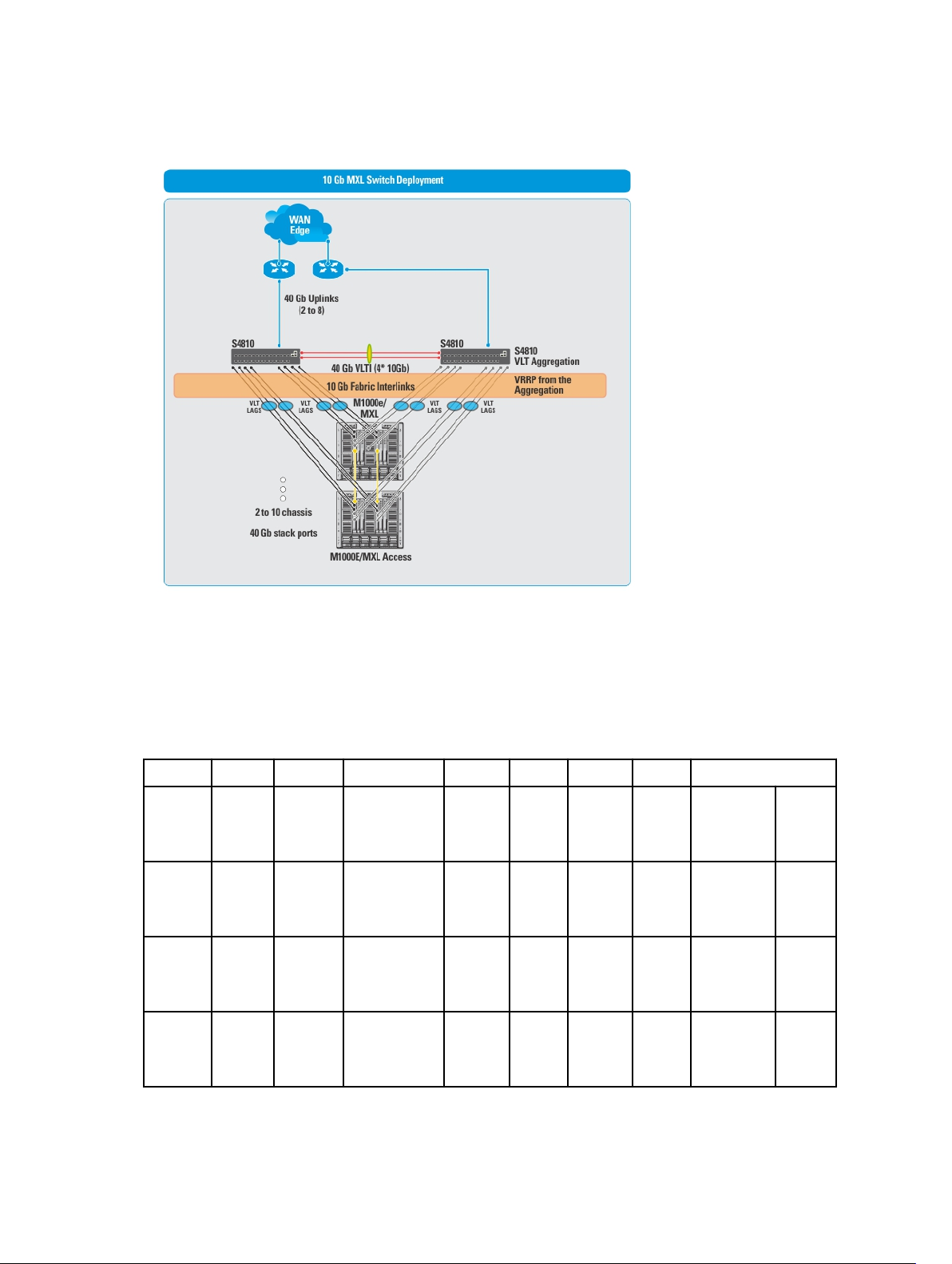
10 Gb Blade Switch (MXL) VLT Deployment
BW = Bandwidth
DL = Downlink
FL BWB A & A = Fabric Link Bandwidth between Aggregation and Access
UL BW = Uplink Bandwidth
VLTi A BW = VLTi Aggregation Bandwidth
Table 9. MXL Blade 2 Tier Topologies for 10 GB MXL Blade Switch For Layer 2 and Layer 3 with Resiliency (Routed VLT)
Possible Topologies
MXL
Blade
Pairs
Range
2 - 27 10 Gb Basic Layer 2/ Layer
2 - 14 10 Gb Basic Layer 2/ Layer
2 - 14 40 Gb Basic Layer 2/ Layer
UL BW Type Fabric Type FL
BWBA &
A
20 Gb 2 * 40 GbNA NA S4810 or
3 with
Resiliency
(Routed VLT)
80 Gb 2 * 40 GbNA NA Z9000 or
3 with
Resiliency
(Routed VLT)
80 Gb 2 * 40 GbNA NA Z9000 or
3 with
Resiliency
(Routed VLT)
VLTi A BWVLTi
Access
BW
MXL
Interchassis
BW
Aggregation Access
S4820T
S6000
S6000
MXL
MXL
MXL
43
Page 44

2 - 26 40 Gb Basic Layer 2/ Layer
3 with
Resiliency
(Routed VLT)
2- 27 10 Gb Stacking Layer 2/ Layer
3 with
Resiliency
(Routed VLT)
2 - 14 10 Gb Stacking Layer 2/ Layer
3 with
Resiliency
(Routed VLT)
2 - 14 40 Gb Stacking Layer 2/ Layer
3 with
Resiliency
(Routed VLT)
2 - 26 40 Gb Stacking Layer 2/ Layer
3 with
Resiliency
(Routed VLT)
2 -27 10 Gb MXL -
intraChassis
resiliency
2 - 14 10 Gb MXL -
intraChassis
resiliency
2 - 14 40 Gb MXL -
intraChassis
resiliency
Layer 2/ Layer
3 with
Resiliency
(Routed VLT)
Layer 2/ Layer
3 with
Resiliency
(Routed VLT)
Layer 2/ Layer
3 with
Resiliency
(Routed VLT)
20 Gb 2 * 40 GbNA NA S4810 or
S4820T
40 Gb 2 * 40 GbNA NA S4810 or
S4820T
160G 2 * 40 GbNA NA Z9000 or
S6000
160G 2 * 40 GbNA NA Z9000/S6000 MXL
40 Gb 2 * 40 GbNA NA S4810 or
S4820T
20 Gb 2 * 40 Gb2 * 40 Gb NA S4810 or
S4820T
80 Gb 2 * 40 Gb2 * 40 Gb NA Z9000/S6000 MXL
80 Gb 2 * 40 Gb2 * 40 Gb NA Z9000/S6000 MXL
MXL
MXL
MXL
MXL
MXL
2 - 26 40 Gb MXL -
intraChassis
resiliency
2 - 30 (for
all even
numbers
only)
2 - 14 (for
all even
numbers
only)
2 - 30 (for
all even
numbers
only)
BW
= Bandwidth
DL = Downlink
FL BWB A & A = Fabric Link Bandwidth between Aggregation and Access
44
10 Gb MXL -
interChassis
resiliency
10 Gb MXL -
interChassis
resiliency
40 Gb MXL -
interChassis
resiliency
Layer 2/ Layer
3 with
Resiliency
(Routed VLT)
Layer 3 with
Resiliency
(Routed VLT)
Layer 3 with
Resiliency
(Routed VLT)
Layer 3 with
Resiliency
(Routed VLT)
20 Gb 2 * 40 Gb2 * 40 Gb NA S4810 or
20 Gb 2 * 40 Gb2 * 40 Gb 40 Gb S4810 or
80 Gb 2 * 40 Gb2 * 40 Gb 40 Gb Z9000 or
20 Gb 2 * 40 Gb2 * 40 Gb 40 Gb S4810 or
MXL
S4820T
MXL
S4820T
MXL
S6000
MXL
S4820T
Page 45

FL BWB C & A = Fabric Link Bandwidth between Core and Access
UL BW = Uplink Bandwidth
VCBW = VLTi Core Bandwidth
Table 10. 3 Tier Deployment Topologies for MXL Blade Switch for Layer 2 and Layer 3 with Resiliency (Routed VLT)
Possible Topologies
MXL
Blade
Pairs
Range
28 - 336 10 Gb Basic Layer 2 or
UL BWType Fabric Type FL
BWB
C &
A
80G 20 Gb 2 * 40 Gb2 * 40 Gb Z9000
Layer 3
with
Resiliency
FL
BWB
A & A
VCBW VLTi
Aggregat
-ion BW
Core Aggregation Access
S4810 or
or
S4820T
S6000
(Routed
VLT)
28 - 336 40 Gb Basic Layer 2 or
Layer 3
with
80G 20 Gb 2 * 40 Gb2 * 40 Gb Z9000
or S6000
S4810 or
S4820T
Resiliency
(Routed
VLT)
15 - 196 10 Gb Basic Layer 2 or
80G 80G 2 * 40 Gb2 * 40 Gb Z9000 Z9000 MXL
Layer 3
with
Resiliency
(Routed
VLT)
15 - 196 10 Gb Basic Layer 2 or
80G 80G 2 * 40 Gb2 * 40 Gb S6000 S6000 MXL
Layer 3
with
Resiliency
(Routed
VLT)
15 - 196 40 Gb Basic Layer 2 or
80G 80G 2 * 40 Gb2 * 40 Gb Z9000 Z9000 MXL
Layer 3
with
Resiliency
(Routed
VLT)
15 - 196 40 Gb Basic Layer 2/
80G 80G 2 * 40 Gb2 * 40 Gb S6000 S6000 MXL
Layer 3
with
Resiliency
(Routed
VLT)
28 - 336 10 Gb Stack-
ing
Layer 2 or
Layer 3
with
80G 40 Gb 2 * 40 Gb2 * 40 Gb Z9000
or S6000
S4810 or
S4820T
Resiliency
(Routed
VLT)
MXL
MXL
MXL
45
Page 46

28 - 336 40 Gb Stack-
ing
15 - 196 10 Gb Stack-
ing
15 - 196 10 Gb Stack-
ing
15 - 196 40 Gb Stack-
ing
15 - 196 40 Gb Stack-
ing
28 - 336 10 Gb MXL -
intraChassis
resilienc
y
27 - 336 40 Gb MXL -
intraChassis
resilienc
y
15 - 196 10 Gb MXL -
intraChassis
resilienc
y
15 - 196 10 Gb MXL -
intraChassis
resilienc
y
Layer 2/
Layer 3
with
Resiliency
(Routed
VLT)
Layer 2 or
Layer 3
with
Resiliency
(Routed
VLT)
Layer 2/
Layer 3
with
Resiliency
(Routed
VLT)
Layer 2/
Layer 3
with
Resiliency
(Routed
VLT)
Layer 2/
Layer 3
with
Resiliency
(Routed
VLT)
Layer 2 or
Layer 3
with
Resiliency
(Routed
VLT)
Layer 2 or
Layer 3
with
Resiliency
(Routed
VLT)
Layer 2 or
Layer 3
with
Resiliency
(Routed
VLT)
Layer 2 or
Layer 3
with
Resiliency
(Routed
VLT)
80G 40 Gb 2 * 40 Gb2 * 40 Gb Z9000
or S6000
80G 160G 2 * 40 Gb2 * 40 Gb Z9000 Z9000 MXL
80G 160G 2 * 40 Gb2 * 40 Gb S6000 S6000 MXL
80G 160G 2 * 40 Gb2 * 40 Gb Z9000 Z9000 MXL
80G 160G 2 * 40 Gb2 * 40 Gb S6000 S6000 MXL
80G 20 Gb 2 * 40 Gb2 * 40 Gb Z9000 or
S6000
80G 20 Gb 2 * 40 Gb2 * 40 Gb Z9000
or
S6000
80G 80G 2 * 40 Gb2 * 40 Gb Z9000 Z9000 MXL
80G 80G 2 * 40 Gb2 * 40 Gb S6000 S6000 MXL
S4810 or
S4820T
S4810 or
S4820T
S4810 or
S4820T
MXL
MXL
MXL
46
Page 47
15 - 196 40 Gb MXL -
intraChassis
resilienc
y
15 - 196 40 Gb MXL -
intraChassis
resilienc
y
Layer 2 or
Layer 3
with
Resiliency
(Routed
VLT)
Layer 2 or
Layer 3
with
Resiliency
(Routed
VLT)
80G 80G 2 * 40 Gb2 * 40 Gb Z9000 Z9000 MXL
80G 80G 2 * 40 Gb2 * 40 Gb S6000 S6000 MXL
47
Page 48

48
Page 49

6
Designing the Fabric
To design a Layer 3 two-tier distributed core fabric or Layer 2 VLT fabric based on your capacity planning for your
current and future needs, use the Fabric Design Wizard at the Network > Design Fabric > New Fabric screen. The design
consists of a wiring plan, network topology information, summary of the inventory requirement, and a design
specification. See also Network Deployment Summary.
This Fabric Design Wizard allows you to perform the following tasks:
• Create a fabric
• Editing and Expanding an Existing Fabric
• Deleting the Fabric
• Import an Existing Fabric Design
• Viewing the Wiring Diagram
• Display the status of the fabric design (whether the design, pre-deployment, deployment, and validation has been
successfully completed.
• Display detailed information about the fabric
Before you begin, review the Getting Started section.
To design a fabric, complete the following tasks using the Fabric Design Wizard.
1. Fabric Design – Step 1: Fabric Name and Type
2. Fabric Design – Step 2: Bandwidth and Port Count
3. Fabric Design – Step 3: Deployment Topology
4. Fabric Design – Step 4: Fabric Customization
5. Fabric Design – Step 5: Output
6. Fabric Design – Step 6: Summary
NOTE: After you finish designing the fabric, prepare it for deployment. For more information, see Preparing the
Fabric for Deployment.
Network Deployment Summary
AFM allows you to design a fabric, make changes to the pre-deployment configuration, deploy the fabric, and validate
the fabric designed by comparing it to a discovered fabric. AFM provides up-to-date status during each phase of the
fabric from design to validate. AFM displays any pending steps required that you needed to ensure the fabric is fully
functional for each fabric design.
Fabric Configuration Phases and States
The following table describes the four fabric phases displayed on the Network >
Deploy screen. To correct the fabric design and pre-deployment configuration before and after you deploy the fabric,
use this information.
Fabric Name
> Configure and Deploy >
49
Page 50

Table 11. Fabric Configuration Phases and States
Phase State State Description
Design Incomplete Indicates that not all required information to complete the design was provided.
Complete Indicates that all required input was provided to complete the design.
Pre-deployment
Configuration
Required Indicates that not all required Pre-deployment Configuration information for any
of the switches was provided.
NOTE: The Pre-deployment Configuration state for all switches is in state
Required.
Error Indicates that deployment error(s) exist for one or more switches.
Partial
Complete
Indicates that Pre-deployment was successfully completed for one or more
switches but not for all switches per design. It provides information about the
count of switches successfully deployment versus the count of total switches
per design.
NOTE: Information provided is sufficient to proceed with deployment of the
subset of switches.
Complete Indicates that Pre-deployment Configuration information is complete for all
switches.
Deployment Required Indicates that the Deployment state for all switches is in the Required state.
In-progress Indicates that Deployment is In-progress (the progress bar displays in the UI) on
one or more switches. It also provides information about the count of switches
successfully deployment versus the count of total switches per design (the
based current port count, doesn’t include the future port count).
Error Indicates that deployment error(s) exist for one or more switches.
Partial
Complete
Indicates that Deployment was successfully completed for one or more switches
but not for all switches per design. It provides information about number of
switches successfully deployed versus the number of total switches in the
design.
NOTE: Deployment on any of the switches is not in-progress while in this
state.
Complete Indicates that deployment was successful for the switch.
Validation Required Indicates that the validation state for all switches is in state Required.
In-progress Indicates that validation is In-progress (progress bar to be displayed in UI) on
one or more switches. It provides information about count of switches
successfully validated vs. count of total switches per design (based current port
count, doesn’t include future port count).
Error Indicates that validation error(s) exist for one or more switches.
Partial
Complete
Indicates that validation was successfully completed for one or more switches
but not all switches per design. It provides information about the count of
switches successfully validated versus the count of total switches per design.
NOTE: Validation of any of the switches is not in-progress during this state.
Complete Indicates that validation was successful for all switches.
50
Page 51

Switch Configuration Phases and States
This section describes the phases and possible states for a switch.
Table 12. Switch Level States
Phase State State Description
Design Complete Indicates that design is complete for the switch.
NOTE: At switch level, design Partial Complete will not be tracked. Partial
Complete will only be tracked at the fabric level.
Pre-deployment
Configuration
Deployment Required Indicates that deployment was never initiated for the switch or the Deployment
Validation Required Indicates that validation was never initiated for the switch or the validation state
Required Indicates that not all required Pre-deployment Configuration information was
provided.
Error Indicates that an error occurred during file transfer (transfer of minimum
configuration file) to FTP/TFTP server or an error occurred during automatic
DHCP integration for local DHCP server.
NOTE: In case of remote DHCP server, no errors will be reported for DHCP
integration step as it is not an automated step from AFM; user is
responsible for manual DHCP integration in this case.
Complete Indicates that Pre-deployment Configuration information is complete for the
switch.
state was reset due to Design/Pre-deployment Configuration change.
NOTE: Deployment can be initiated/re-initiated only if Pre-deployment
Configuration is in state Complete
In-progress Indicates that Deployment is in-progress and also provides the latest percentage
complete information.
Error Indicates that deployment error exists.
Complete Indicates that deployment was successful for the switch.
was reset due to Design/Pre-deployment Configuration/Deployment change.
NOTE: Validation can be initiated only if Deployment is in state Complete.
In-progress Indicates that deployment is in-progress and also provides the latest percentage
complete information.
Error Indicates that one or more validation error exists.
Complete Indicates that validation was successful for the switch.
Using the Fabric Design Wizard
Use the Fabric Design Wizard at the Network > Design Fabric > New Fabric screen to design the following types of
customized fabrics based on your workload requirements for your current and future needs.
• Layer 2 — Use the Layer 2 VLT fabric for workload migration over virtualized environments. See VLT and Selecting a
Layer 2 and Layer 3 with Resiliency (Routed VLT) fabric.
51
Page 52

• Layer 3 distributed core — Use the Layer 3 distributed core for large fabric deployments. See Conventional Core
Versus Distributed Core
• Layer 3 with Resilency (Routed VLT) — Use the Layer 3 fabric to extend equal cost multi-pathing capabilities. See
Selecting a Layer 2 and Layer 3 with Resiliency (Routed VLT).
This screen allows you to create, edit, delete, and view the fabric.
NOTE: You can also use the Fabric Design Wizard from the Home > Design New Fabric screen.
Use the following screens to design a fabric:
1. Fabric Name and Type — Displays the fabric name, type, and description. Enables Openstack Neutron
Management and Blade Switch deployment.
2. Bandwidth and Port Count— Displays the number of edge port uplinks to the WAN connection, and downlinks (for
example, to servers or ToRs) required for the initial deployment as well as for future expansion.
3. Deployment Topology — Displays the option to select between a Layer 2 or Layer 3 solution and a list of all
applicable deployment topologies based on the workload requirements that you entered on the Bandwidth and Port
Count and Fabric Name and Type screens. This screen also displays Advanced options for configuring VLTi links
and fabric links. See also
4. Fabric Customization — Displays switch names, model, and switch role (aggregation or access) and modifies the
fabric link bandwidth for 2-tier and 3-tier fabrics. For a Layer 2 deployment topology, you can select S4810 or
S4820T switches (mixed node) on the access side.
5. Output — Displays future switches and links and the fabric in the following formats:
– graphical wiring plan
– tabular wiring plan
– graphical network topology
– tabular network topology
Deployment Topology Use Cases.
6. Summary — Displays a summary of the fabric design. You can also export the design in XML format and then
import the XML design back into AFM.
Fabric Design – Step 1: Fabric Name and Type
To simplify and automate the design process, AFM provides a fabric design wizard to help you design a Layer 2, Layer 3,
or Layer 3 with Resiliency (Routed VLT) fabric based on the your current and future datacenter capacity requirements.
See Designing the Fabric, Using the Fabric Design Wizard, and Supported Fabric Types.
To generate a physical wiring diagram for the fabric during the design phase, enter your data center capacity
requirements. The wiring diagram is typically given to the network operator who uses it to build the physical network.
For information about designing a fabric, see Selecting Distributed Core and Selecting a Layer 2 and Layer 3 with
Resiliency (Routed VLT) .
To configure the fabric name and type:
1. Navigate to the Fabric Design Wizard at the Network > Design Fabric screen.
2. Click the New Fabric link.
The Introduction screen is displayed.
3. Review the introduction and click the Next button.
The Fabric Name screen displays.
52
Page 53

4. Enter the name of the fabric in the Fabric Name field.
The fabric name must be a unique name. It can have from 1 to 17 characters. Valid characters are as follows:
– alphanumeric
– underscore ( _ )
– +
When you specify the name of the fabric, AFM automatically names the switches in the fabric with the fabric name
as the prefix. For example, if the name of the fabric is EastFabric, the switch names assigned are EastFabricSpine-1 and EastFabric-Leaf1.
5. (Optional) In the Description field, enter the description of the fabric.
There is no character restriction. The length of the description can be from 1 and 128 characters.
6. If you are using the AFM Openstack, check the OpenStack Neutron Managed option.
NOTE: When you select this option, you cannot enter the VLAN configuration in the AFM Pre-Deployment
Wizard. This is handled by OpenStack which requires the AFM Neutron Plug-in installation which
orchestrates the Layer 2 VLAN configuration between OpenStack and AFM. See the
Openstack Guide
7. To include blade switches (MXLs), check the Blade switch (MXL) deployment option. This option is for a Layer 2
fabric or Layer 3 with Resiliency (Routed VLT) fabric.
8. Click Next to go to the Bandwidth and Port Count screen to review the uplink and downlink bandwidth settings.
Uplinks connect from the fabric up to the next upstream tier of devices towards the core of the network. Downlinks
connect from the fabric down to the next tier of devices or servers towards the edge of the network.
.
AFM Plug-in for
Fabric Design – Step 2: Bandwidth and Port Count
The Bandwidth and Port Count screen displays the default values for the fabric uplinks and downlinks. Uplinks connect
from the fabric up to the next upstream tier of devices toward the core of the network. The minimum number of uplinks is
2. One uplink is for redundancy. Downlinks connect from the fabric down to the next tier of devices or servers towards
the edge of the network. These values (1 Gb, 10 Gb, or 40 Gb) are based on the options you have selected in the
Name and Type screen. The number of uplink ports, downlink ports, and bandwidth you enter are the major input
parameters in the design phase.
Fabric
53
Page 54

54
Page 55

To configure bandwidth and port count for the switches in the fabric:
1. In the Bandwidth Specification:
a) Select the uplink bandwidth (10 Gb or 40 Gb) using the Uplink Bandwidth pull-down menu.
b) Select the downlink bandwidth (1 Gb, 10 Gb, or 40 Gb) using the Downlink Bandwidth pull-down menu.
– When you select the 1 Gb Downlink Bandwidth option, the AFM supports deployment topologies with the S55
and S60 switches on the access side.
– When you select the 10 Gb Downlink Bandwidth option, the AFM supports all the deployment topologies with
the S4810 and S4820T switches on the access side.
– When you select the 40 Gb Downlink Bandwidth option, the AFM supports deployment topologies with the
Z9000 and S6000 switches on the access side.
2. In the Number of edge ports required by the fabric
a) In the Uplink Ports Current column, enter an even number of uplink ports (connections to the WAN) required by
the fabric for initial deployment. The minimum number of uplinks is 2. One uplink is for redundancy. For a 10 Gb
bandwidth, AFM supports 2 to 32 uplinks. For a 40 Gb Bandwidth, AFM supports 2 to 8 uplinks.
* For a Layer 2 VLT fabric and Layer 3 with Resiliency (Routed VLT) fabric, an edge port link (uplinks) from the
aggregation or core switches that connect outside the fabric. For a 3 tier it is core, for a 2 tier it is
aggregation.
* For Layer 3 distributed core, an edge port link (uplinks) on the first two leaves that connects to the edge
WAN, which typically connects to an internet service provider (ISP).
b) In the Downlink Ports Current column, enter an even number of downlink ports (2 to the maximum number of
available ports) required by the fabric for initial deployment. The default is 2 downlink ports.
c) In the Uplink Ports Future column area, enter the number of uplink ports (connections to the WAN) required by
the fabric for future expansion of the fabric. If the future ports are not reserved, you cannot expand the fabric in
the future.
d) In the Downlink Ports Future column area, enter an even number of downlink ports (connections to the servers,
switches, or ToR) required by the fabric for future expansion of the fabric.
NOTE: When you select the Blade switch (MXL) deployment option in the Fabric Name and Type screen,
the Bandwidth and Port Count screen displays a Blade Switch Pairs option instead of a Downlink Ports
option in the Number of edge ports required by the fabric area.
3. Review the values and then click the Next button to go to the Deployment Topology screen.
Deployment Topology Use Cases
Use the following use cases as a guide to select a deployment topology.
• Use Case 1: 1 Tier Layer 2 Fabric
• Use Case 2: 1 Tier Layer 3 with Resiliency (Routed VLT)
• Use Case 3: 2 tier Layer 3 Distributed Core
• Use Case 4: 2 Tier Layer 3 Resiliency (Routed VLT)
• Use Case 5: 3 Tier Layer 2
• Use Case 6: 3 Tier Layer 3 Resiliency (Routed VLT)
Use Case 1: 1 Tier Layer 2 Fabric
When you select a 1 Tier Layer 2 fabric:
• The uplinks between the 2 aggregation switches and external switch (WAN) supports the Layer 3 protocol (OSPF,
iBGP or eBGP).
55
Page 56

• The downlinks from the 2 aggregation switches supports the Layer 2 protocol (VLAN or VLAN/VRRP). The default
setting on the pre-deployment screen is VLAN configuration which allows you to configure downlink
connections to servers. To support redundancy between the aggregation switches and ToR switches, select the
VLAN and VRRP Configuration option.
Figure 11. Example: Tier 1 with Layer 2 VLT fabric Deployment Topology
Figure 12. Example: Tier 1 with Layer 2 VLT fabric Graphical View
56
Page 57

Use Case 2: 1 Tier Layer 3 with Resiliency (Routed VLT)
When you select a 1 tier Layer 3 with Resiliency (Routed VLT) fabric:
• The uplinks between the 2 aggregation switches and external switch (WAN) supports the Layer 3 protocol (OSPF,
iBGP or eBGP).
• The downlinks from the 2 aggregation switches supports the Layer 2 protocol (VLAN/VRRP or VLAN IP). During the
design phase at the Deployment Topology screen, you select the fabric type and deployment type (topology). In this
example shown below, a Layer 3 with Resiliency (Routed VLT) fabric. Based on the deployment type option selected,
different downlink options are configured in the access tier.
Use Case 3: 2 Tier Layer 2
When you select a 2 tier Layer 2 VLT fabric:
• The fabric links between aggregation and access switches supports the Layer 2 protocol.
• The uplinks between the aggregation switches and external switch (WAN) supports the Layer 3 protocol (OSPF,
iBGP or eBGP).
• The downlinks from the access switches supports the Layer 2 protocol (VLAN or VLAN/VRRP). The default setting on
the pre-deployment screen is VLAN configuration which allows you to configure downlink connections to servers.
Select the “VLAN and VRRP Configuration” option to support redundancy between the access switch and ToR
switches.
Figure 13. Example: 2 Tier Layer 2 VLT Fabric
Use Case 3: 2 tier Layer 3 Distributed Core
When you select a 2 tier Layer 3 distributed core fabric:
• The fabric links between the spine and leaf switches supports the Layer 3 OSPF routing protocol.
• The uplinks between spine switch and external switch (WAN) supports the Layer 3 protocol (OSPF, iBGP or eBGP).
57
Page 58
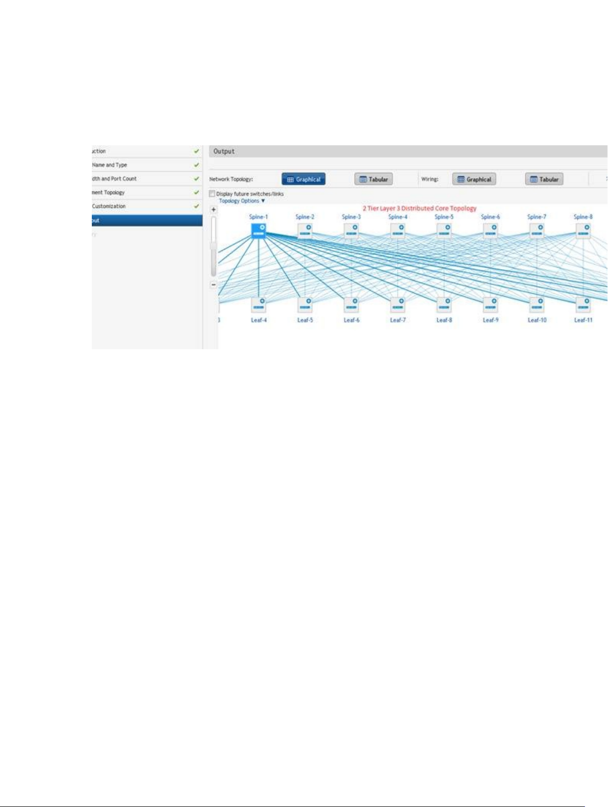
• The downlinks from the access switches supports the Layer 2 protocol (VLAN or VLAN and LAG).
– If the VLAN option is selected, the downlinks connecting to server is configured to use the VLAN protocol.
– If the VLAN and LAG option is selected, the downlinks between the leafs and ToR is configured to use VLAN,
VRRP, and LAG for redundancy.
Figure 14. Example: 2 tier Layer 3 Distributed Core
Use Case 4: 2 Tier Layer 3 Resiliency (Routed VLT)
When you select a 2 tier Layer 3 with Resiliency (Routed VLT) fabric:
• The fabric links between the aggregation and access switches supports the Layer 3 protocol with OSPF in the VLAN
interfaces.
• The uplinks between the aggregation switch and external switch (WAN) supports the Layer 3 protocol (OSPF, iBGP
or eBGP).
• The downlinks from the access switches supports the Layer 2 protocol (VLAN/VRRP or VLAN IP). During the design
phase at the Deployment Topology screen, you select the fabric type and deployment type (topology). In this
example shown below, a Layer 3 with Resiliency (Routed VLT) fabric. Based on the deployment type option selected,
the different options to be configured in downlink at the access tier.
The following section lists the topology types that you can select:
1. Layer 3 with Resiliency (Routed VLT) with stacking option – When you select the Stacking option, configure the
VLAN with the primary and secondary IP addresses for each access switch.
58
Page 59
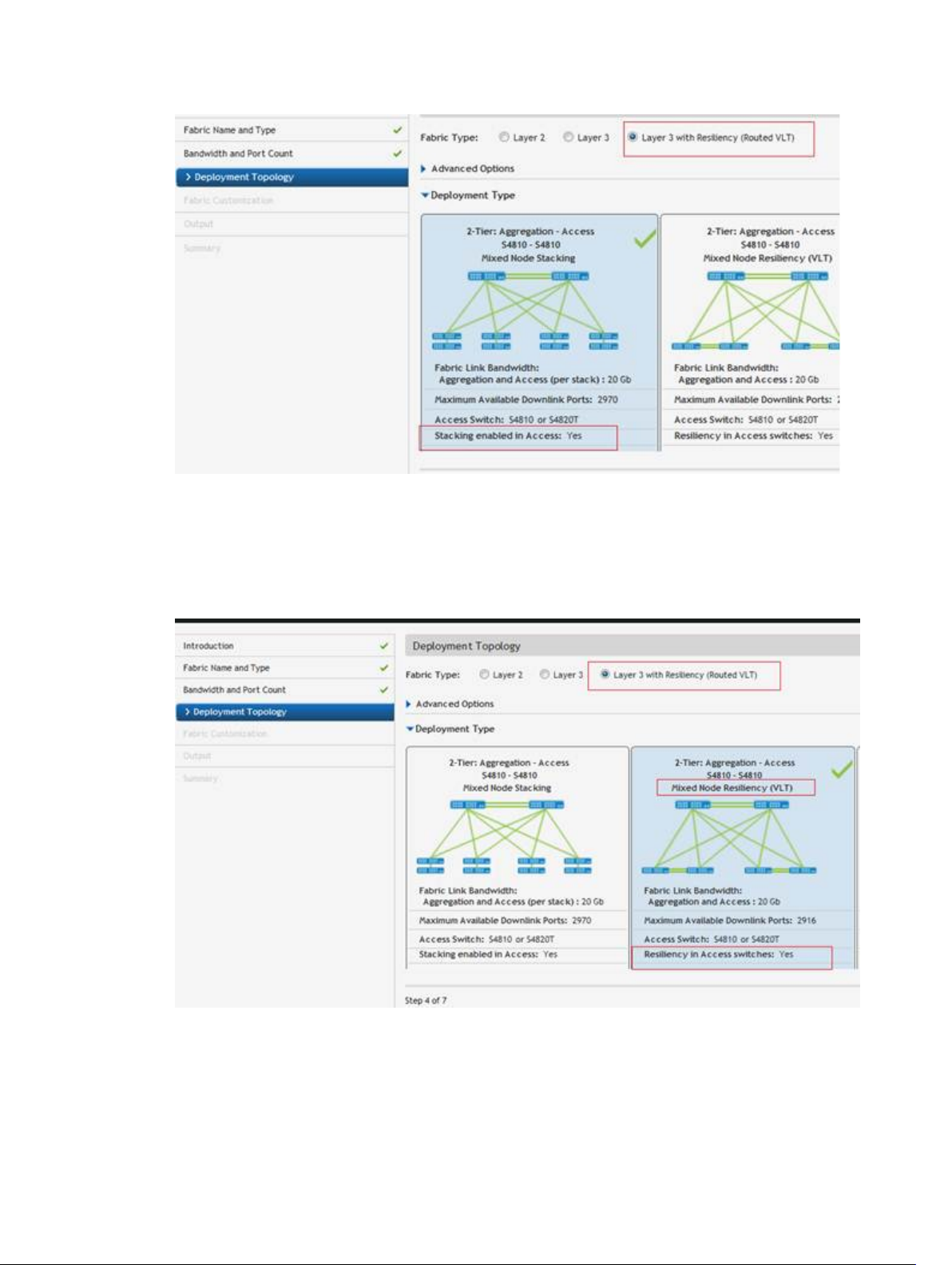
Figure 15. Example: 2 Tier Layer 3 with Resiliency (Routed VLT) with Stacking Option
2. Layer 3 with Resiliency (Routed VLT) with VLT option – When you select the VLT option, the default configuration is
to enter the VLAN ID, Primary IP address and Secondary address. If you select the Enable Layer 3 Protocol in
Access Switches option, configure the VLAN ID and then the IP Range. When you complete the pre-deployment
configuration, the Advanced VLAN IP Configuration option is available at the Configure and Deploy Summary
screen.
Figure 16. Layer 3 with Resiliency (Routed VLT) with VLT option
59
Page 60
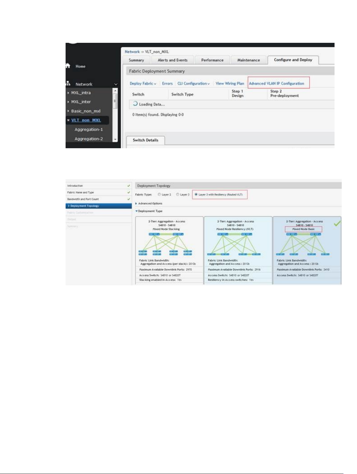
Figure 17. Layer 3 with Resiliency (Routed VLT) with VLT option + Advanced VLAN IP Configuration
3. Layer 3 with Resiliency (Routed VLT) – Basic option – When you select the Basic option, configure the VLAN with
the primary and secondary IP addresses for each access switch.
Figure 18. Layer 3 with Resiliency (Routed VLT) with Basic Option
4. Layer 3 with Resiliency (Routed VLT) with MXL Blade with interChassis option – With this topology , you select the
Deployment Type that has a MXL Blade switch with Resiliency (VLT) and Interchassis (across Chassis) resiliency.
Enter the VLAN ID and the IP range. When you complete the pre-deployment configuration, the Advanced VLAN IP
Configuration option is available at the “Configure and Deploy” Summary screen.
60
Page 61
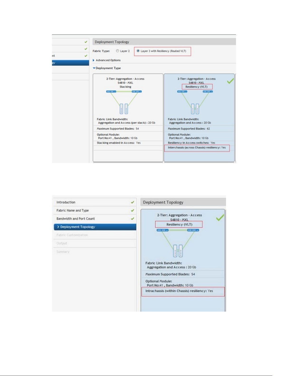
Figure 19. Layer 3 with Resiliency (Routed VLT) with MXL Blade with interChassis option
5. Layer 3 with Resiliency (Routed VLT) – Blade MXL with IntraChassis option: With this topology, you select the
deployment type using that has a MXL Blade switch with Resiliency (VLT) and Intrachassis (within the same
chassis) resiliency option. Enter the VLAN ID, primary and secondary IP addresses.
Figure 20. Layer 3 with Resiliency (Routed VLT) Blade MXL with IntraChassis option
61
Page 62
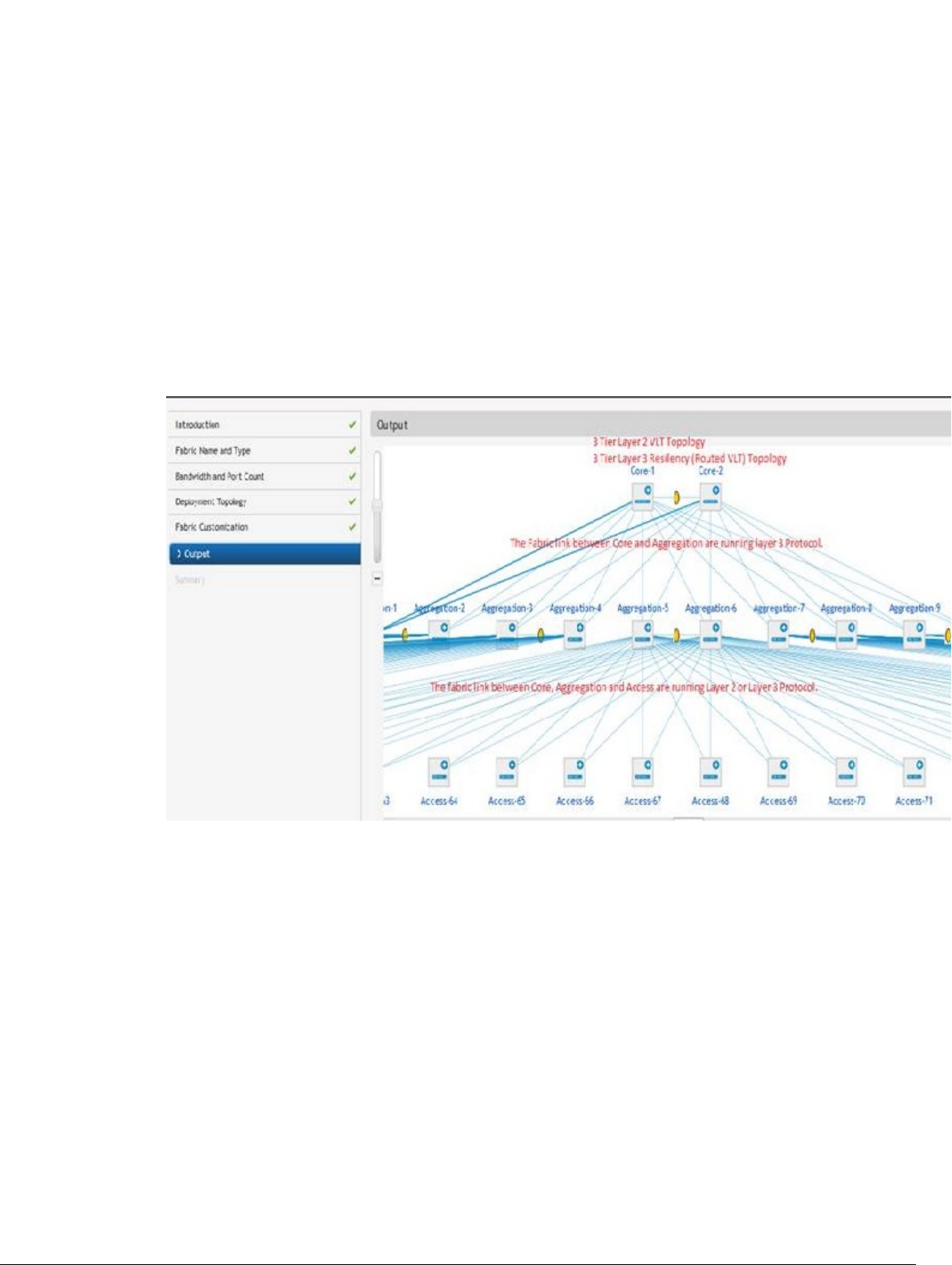
Use Case 5: 3 Tier Layer 2
When you select a 3 tier Layer 2 fabric:
• The fabric links between core and aggregation switches supports the Layer 3 protocol.
• The fabric links between aggregation and access switches supports the Layer 2 protocol.
• The uplinks between the aggregation switches and external switch (WAN) supports the Layer 3 protocol (OSPF,
iBGP or eBGP).
• The downlink from the access switches supports the Layer 2 protocol (VLAN or VLAN/VRRP). The default setting on
the pre-deployment screen is VLAN configuration which allows you to configure downlink connections to servers.
Select the VLAN and VRRP Configuration option to support redundancy between the access switch and ToR
switches.
Figure 21. 3 Tier Layer 2 VLT Topology
Use Case 6: 3 Tier Layer 3 Resiliency (Routed VLT)
When you select a 3 tier Layer 3 with Resiliency (Routed VLT) fabric:
• The fabric links between core and aggregation switches supports Layer 3 protocol with OSPF in the VLAN
interfaces.
• The fabric links between the aggregation and access switches supports the Layer 2 protocol the Layer 2 protocol.
• The uplinks between the aggregation switch and external switch (WAN) supports the Layer 3 protocol (OSPF, iBGP
or eBGP).
• The downlinks from the access switches supports the Layer 2 protocol (VLAN/VRRP or VLAN IP). During the design
phase at the Deployment Topology screen, you select the fabric type and deployment type (topology). In this
62
Page 63
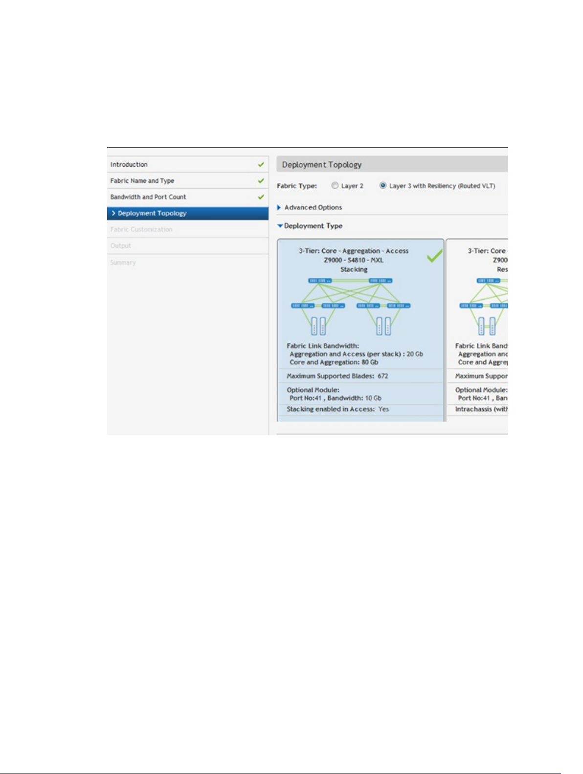
example shown below, a Layer 3 with Resiliency (Routed VLT) fabric. Based on the deployment type option selected,
different downlinks options are configured at the access tier.
The following section lists the topology types that you can select:
1. Layer 3 with Resiliency (Routed VLT) with stacking option – When you select the Stacking option, configure the
VLAN with the primary and secondary IP addresses for each access switch.
Figure 22. 3 Tier Layer 3 with Resiliency (Routed VLT) with Stacking Option
2. Layer 3 with Resiliency (Routed VLT) with VLT option – When you select the VLT option, the default configuration
is to enter the VLAN ID, Primary IP address and Secondary address. If you select the Enable Layer 3 Protocol in
Access Switches option, configure the VLAN ID and then the IP Range. When you complete the pre-deployment
configuration, the Advanced VLAN IP Configuration option is available at the Configure and Deploy summary
screen.
63
Page 64

Figure 23. Example: 3 Tier Layer 3 with Resiliency (Routed VLT) with VLT option
Figure 24. 3 Tier Layer 3 with Resiliency (Routed VLT) with VLT Option + Advanced VLAN IP Configuration
3. Layer 3 with Resiliency (Routed VLT) – Basic option – When you select the Basic option, configure the VLAN with
the primary and secondary IP addresses for each access switch.
64
Page 65
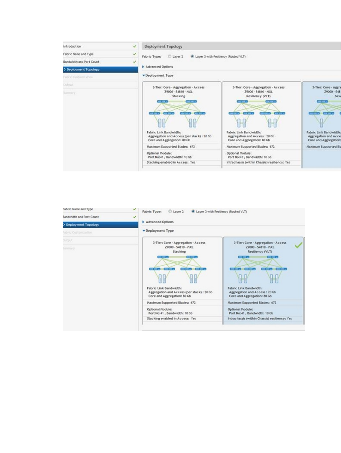
Figure 25. Example: 3 Tier Layer 3 with Resiliency (Routed VLT) with Basic Option
4. Layer 3 with Resiliency (Routed VLT) – Blade MXL with IntraChassis option: With this topology , you select the
deployment type that has a MXL Blade switch with Resiliency (VLT) and Intrachassis (within the same chassis)
resiliency option. Enter the VLAN ID, primary and secondary IP addresses.
Figure 26. Tier 3 Layer 3 with Resiliency (Routed VLT) Blade MXL with IntraChassis option
Fabric Design – Step 3: Deployment Topology
The AFM displays applicable deployment topologies based your datacenter workload requirements specified in the
Fabric Name and Type and Bandwidth and Port Count screens. By default, AFM selects one of the topologies. Click the
65
Page 66

deployment topology filter icon on the top right of the screen to display additional deployment topology options. The
output from these screens and the Deployment Topology and Fabric Customization screens create a network topology
and the detailed wiring plan. See also Deployment Topology Use Cases.
Based on your design requirements you can create a 1, 2, or 3 tier topology as shown below
• Tier 1 Topology — Contains 2 switches and a downlink and uplink configuration. There are no fabric links.
Figure 27. VLT 1 Tier Topology: Aggregation Layer
For more information about the tier 1 topologies, see Designing a Layer 2 VLT and Layer 3 with Resiliency (Routed
VLT) Fabric.
• Tier 2 Topology — Contains 2 layers of switches, has fabric interlinks, uplinks and downlinks. Distributed Core (spine
and leaf) or VLT (aggregation and access). For more information about tier 2 topologies, see Designing a Layer 2 VLT
and Layer 3 with Resiliency (Routed VLT) Fabric and Selecting a Layer 3 Distributed Core Fabric Design.
Figure 28. Tier 2 VLT Topology: Aggregation and Access Layer
Figure 29. Tier 2 Distributed Core Topology: Spine and Leaf
• Tier 3 Topology — Layer 3 with Resiliency (Routed VLT) has 3 layers of switches, fabric interlinks, uplinks and
downlinks. For more information about the tier 3 topologies, see Designing a Layer 2 VLT and Layer 3 with Resiliency
(Routed VLT) Fabric .
Figure 30. Tier 3 VLT Topology Core: Aggregation - Access Layer
The following illustration and table describes the deployment types for a fabric.
66
Page 67

NOTE: For topologies, refer to the Designing a Layer 2 VLT and Layer 3 with Resiliency (Routed VLT) Fabric and
Selecting a Layer 3 Distributed Core Fabric Design.
Table 13. Deployment Topology (Filter) Options
Deployment Options Description
Over Subscription Ratio
(Layer 3 distributed core deployment
topology only)
For the layer 3 deployment the following over-subscription ratios are
available:
• 1:1
• 3:1
• 4:1
• 5:1
Resiliency in Access Devices Configures Virtual Router Redundancy Protocol (VRRP) on the downlink.
10 Gb Cable Type for Access Tier This option is applicable only for the topologies in which S4810 and S4820T
can be swapped with each other.
• SFP+
• RJ-45
Stacked/Non-Stacked Selects stacking for the topologies that are applicable. When you select
stacking, you can use VLTi.
High Stream Buffering
• high stream buffing — The access layer uses S60 switches.
67
Page 68

• low latency — The access layer uses S55 switches
Resiliency In MXL (Routed VLT)
• Intra-chassis — Within the chassis (mVLT)
• Inter-chassis resiliency — Across 2 chassis (VLT)
This section contains the following topics:
• (Optional) Configuring Advanced Options
• Selecting the Fabric Deployment Type
(Optional) Configuring Advanced Options
For a Layer 2 or Layer 3 with Resiliency (Routed VLT) fabric, you customize the bandwidth between the aggregation and
access switches. When you configure the fabric link bandwidth between aggregation and access switches from the
Enabled Link Bandwidth Customization option from the Deployment Topology screen, the bandwidth selected is shared
equally by 2 redundant links. For example, if you select a fabric link bandwidth of 80 Gb between the aggregation and
access switches, you can configure 40 GB for each redundant link on the Fabric Customization screen.
To configure the deployment type so that you can customize the fabric link bandwidth between the aggregation and
access switches:
1. In the Deployment Topology, check one of the following options:
– Layer 2
– Layer 3 with Resiliency (Routed VLT)
2. Check the Enabled Link Bandwidth Customization option.
Figure 31. Enabled Link Bandwidth Customization Option
3. In the Fabric Link Core Aggregation and aggregation and Access option (only the applicable options for a select
topology are configurable), select the fabric bandwidth value from the Aggregation and Access pull-down menu.
For example, for 2 tier topology, selecting the 120 Gb bandwidth option allows you to later customize the
bandwidth from 20 to 120 Gb in increments of 20 Gb in the Fabric Customization screen.
4. Click the Refresh Deployment Type button.
68
Page 69

5. On the Deployment Type, select the appropriate deployment type.
6. Click the deployment topology filtering icon on the top right of the screen to display deployment topology options.
Only applicable options are displayed.
7. Configure the filter options for the deployment topology and click the Apply button.
8. Click the Next button to go to the Fabric Customization screen.
9. (Optional) From the Fabric Link Bandwidth pull-down menu, select the fabric link bandwidth for each switch that
you want to customized.
Figure 32. Customizing Fabric Link Bandwidth between Switches
10. Click the Next button to go to the Output screen.
Selecting the Fabric Deployment Type
To select the fabric deployment type:
69
Page 70

Figure 33. Layer 3 with Resiliency (Routed VLT) : Deployment Type screen
1. Navigate to the Network > Design Fabric > New Fabric > Deployment Topology screen.
2. In the Fabric Type area, select one of the following fabric types:
a) Layer 2 — Use the Layer 2 VLT fabric for workload migration over virtualized environments. See VLT and
Selecting a Layer 2 VLT and Layer 3 with Resiliency (Routed VLT) Fabric Design.
b) Layer 3 — Use the Layer 3 distributed core for large fabric deployments. See Conventional Core Versus
Distributed Core.
c) Layer 3 with Resilency (Routed VLT) — Use the Layer 3 fabric to extend equal cost multi-pathing capabilities.
See Selecting a Layer 2 VLT and Layer 3 with Resiliency (Routed VLT) Fabric Design.
3. Click on the deployment topology that contains the appropriate core switches and aggregation switch type that you
want in your fabric and for a Layer 3 distributed core fabric, the over-subscription ratio.
4. (Optional) Click the Advanced Options to configure VLTi links and fabric links.
a) VLTi and Fabric Link options
* VLTi link
• Core — Specify the number of links and bandwidth.
• Aggregation — Specify the number of links and bandwidth.
• Access — Specify the number of links and bandwidth.
* Fabric Link
• Core and Aggregation — Specify the bandwidth.
• Aggregation and Access — Specify the bandwidth.
b) Click the Refresh Deployment Type button to apply the Advanced Options to view the new deployment
topologies.
70
Page 71

5. Click the deployment topology filter icon on the top right of the screen to display deployment topology options. Only
applicable filter options are displayed. For a description about the filtering options, refer to the Deployment
Topology Options table.
6. Configure the filter options for the deployment topology and click the Apply button.
7. Click the Next button to go to the Fabric Customization screen.
Fabric Design – Step 3: Fabric Customization
To modify the fabric link bandwidth (between the aggregation and access switches) for 2-tier and 3-tier fabrics, use the
Fabric Customization screen. This screen displays the switch names, model, and switch role (spine, leaf, aggregation or
access). For a Layer 2 or Layer 2 with Resiliency (Routed VLT) deployment topology, you can select S4810 or S4820T
switches (mixed node) on the access side.
Pre-requisites
To use this feature, you must first configure the Advance Configuration option, Fabric Link between Aggregation and
Access, to the maximum bandwidth for each access switch; for example, 120 Gb, at the Network > Design Fabric > New
Fabric > Deployment Topology screen. If you do not configure this option, the Fabric Customization screen will be a
71
Page 72

read-only screen. For information about the Advanced Options, see the section at Configuring Advanced Options. For
information about tiers, see Deployment Topology. See also Deployment Topology Use Cases.
1. Navigate to the Network > Design Fabric > New Fabric > Deployment Topology > Fabric Customization screen.
2. From the Fabric Link Bandwidth pull-down menu, select the fabric link bandwidth for each access switch.
3. Click the Next button to go the Output screen.
Fabric Design – Step 5: Output
To view the graphical wiring, tabular wiring, and network topology wiring plans for your fabric design, use the Output
screen. Use the wiring plan as a guide for installing your equipment into the fabric. Based on the configuration, the AFM
calculates the number of switches required for the design and displays the physical wiring plan which you can export
and print in PDF or Microsoft Visio® 2010. The wiring plans display the cabling maps (the connections between the
switches) and the switches and links for current and future expansion. Review the wiring plan and then export it to a file.
Typically, after the fabric design is approved, the wiring plan is given to your data center operator who uses this
information to build the physical network according to the fabric design.
The fabric design is displayed in the following formats:
72
Page 73

• Graphical Wiring Plan — Displays information about how the switches are connected graphically.
• Network Topology — Displays information about how the switches are connected physically using a topology map.
By default, no links are displayed in the fabric. Click on a switch to display the links in the fabric. When you select a
switch, all the fabric interlinks are displayed. When you select a spine switch the links to the leaf switches are
displayed. When you select an aggregation switch, the links to the access switches are displayed. Similarly, when
you select a leaf switch, the links to the spine switches are displayed. When you select the access switches, the
links to aggregation switches are displayed. When you select the core switches, the links to all the switches in the
73
Page 74
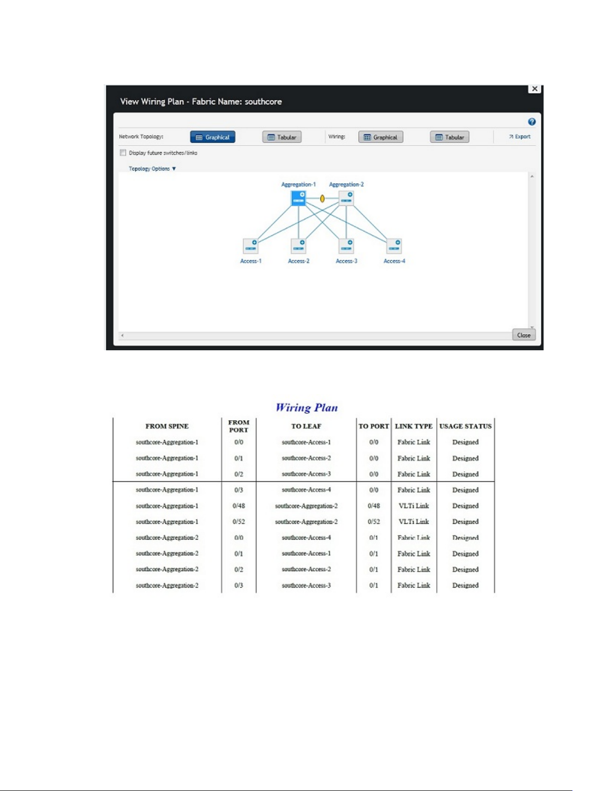
fabric (aggregation and access) are displayed.
• Tabular Wiring Plan — Displays information about how the switches are connected in the fabric design in a tabular
format, as shown below. The tabular wiring plan contains a list of switches along with their names and ports which
connect to the ports on the other switches in the fabric.
74
Page 75
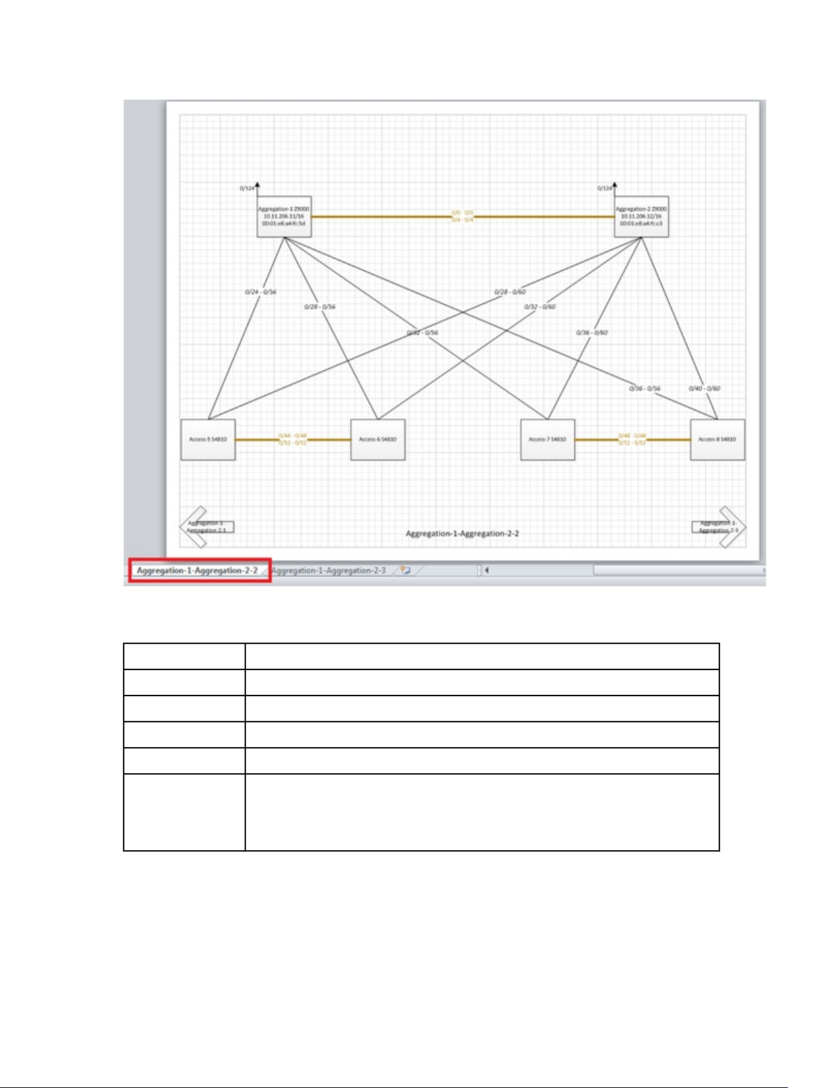
Figure 34. Example: Visio Output
Table 14. Tabular Wiring Plan Output Descriptions
Field Name Description
From Device (Switch) Displays the name of the device — from the side.
From Port Displays the port number on the switch — from the side.
To Device (Switch) Displays the name of the device— to the side.
To Port Displays the port number on the device — to the side.
Usage Status
• Current — Represents the links based on your current needs.
• Future — Represents links based on the fabric’s future needs.
• Displays usage status: current and future expansion.
To review and export the fabric wiring plan
:
1. Navigate to the Network > Design Fabric > New Fabric > Output screen.
2. Click on the type of wiring plan that you want to export: Wiring (Graphical or Wiring) , or Network Topology
(Graphical or Tabular format).
75
Page 76

3. Click the Export link.
The Generate Wiring Plan window displays.
4. Specify the following export options.
a) PDF — Table, Data, Graphical Wiring Plan, or Both.
b) Visio — Network Topology.
5. Click the Generate button.
Fabric Design – Step 6: Summary
The Summary screen displays a summary of your fabric design.
To export the fabric design:
1. Click one of the following export options:
– Export Wiring Plan
– Export Summary
– Export Design
2. Select a display format: PDF (Table Data, Graphical Wiring Plan, Both) or Visio.
3. Click the Generate button.
4. Carefully review the design before you commit the changes.
5. Click Finish to commit your changes.
Next Steps
After you have designed the fabric, do the following to prepare it for deployment:
1. Check with your system administrator for the TFTP or FTP IP address. To stage the switch software images, use this
address. When you prepare the software images:
a) Make sure the software version is the same for each type of switch across the fabric.
b) Download the software image for each type of Dell Networking switch.
c) Stage the software images on the TFTP or FTP site.
2. Obtain a pool of management IP addresses from the lab or system administrator to use for the switches in the
fabric.
3. Prepare the DHCP server so that the switches can be assigned a management IP address.
4. Download the comma separate values (.csv) file that contains the switch system MAC address provided from Dell
manufacturing, if available. If not available, consult Dell customer support. If you do not have this file, record the
system MAC addresses of the switches in the fabric so that you can then map (associate) the address to the
appropriate switch before you rack the switches.
5. Print out the wiring plan and use it to rack and cable the hardware according to the fabric design wiring plan.
6. Document the location of the switches, including the rack and row.
7. Select the fabric you are performing pre-deployment on at the Network >
Pre-deployment Configuration screen.
Fabric Name
> Configure and Deploy >
Importing an Existing Fabric Design
To import an existing fabric design:
1. Navigate to the Home > Getting Started screen.
2. Click the Importing Existing Design option.
The Import Existing Design screen displays.
76
Page 77

3. In the Fabric XML file area, click the Browse button and locate the fabric XML design file (the XML design that you
have exported from the AFM design wizard).
4. Click the Upload button.
Editing and Expanding an Existing Fabric Design
You can edit or expand an existing fabric from the Getting Started screen. After you initiated the pre-deployment
configuration, you can only update the fabric description and port count for expanding uplinks and downlinks.
1. Navigate to the Home > Getting Started screen.
2. Click the Edit Existing Fabric button.
The Select a Fabric screen displays.
3. Select a fabric to edit and then click the OK button.
The Fabric Designer wizard displays.
4. Edit the fabric.
Deleting the Fabric
To delete a fabric:
1. Navigate to the Network screen.
2. Select the Design Fabric tab.
3. Select the fabric to delete.
4. Click the Delete Fabric link.
Viewing the Wiring Diagram
To view and export the wiring diagram of the fabric:
1. Navigate to the Network > Design Fabric screen.
2. Select the fabric and then click the View Wiring Plan link
3. If you want to display future switches and links, click the Display future switches/links option.
4. Click one of the following options:
a) Tabular Wiring Plan
b) Graphical Wiring Plan
c) Network Topology Plan
d) Network Topology Tabular Plan
5. Click the Export link to export the wiring plan.
77
Page 78

78
Page 79

7
Configuring and Deploying the Fabric
After you create a fabric at the Network > Design Fabric > New Fabric screen, you can configure and deploy the fabric
at the Network >
the fabric. You can deploy auto-generated and custom configurations. This screen contains the following options:
• Deploy Fabric — Prepares the fabric for deployment and deploys the fabric.
– Pre-deployment Configuration
– Deploying and Validate
– View DHCP Configuration
• Errors — Displays errors in the fabric
Related Links:
– Deployment and Validation Errors
Troubleshooting
• CLI Configuration — Template and custom configuration using the FTOS CLI commands.
– Manage Templates
– Associate Templates
– Custom Configuration
– Viewing Custom Configuration History
• View Wiring Plan — Displays the wiring plan in tabular, network topology, and graphical formats, which can be
exported.
Fabric Name
> Configure and Deploy screen. This screen deploys the configuration to the switches in
Related Links:
• Pre-deployment Configuration
• Using the Pre-deployment Configuration Wizard
Fabric Deployment Summary
Switch Configuration Phases and States
Table 15. Switch Configuration Phases and States
Phase State State Description
Design Complete Indicates that the design is complete for the switch.
NOTE: At switch level, design Partial Complete is not tracked. Partial
Complete is only tracked at the fabric level.
79
Page 80

Pre-deployment
Configuration
Deployment Required Indicates that deployment was never initiated for the switch or the Deployment
Validation Required Indicates that validation was never initiated for the switch or the Validation state
Required Indicates that not all required Pre-deployment Configuration information was
provided.
Error Indicates that an error occurred during file transfer (transfer of a minimum
configuration file) to the FTP/TFTP server or an error occurred during automatic
DHCP integration for the local DHCP server.
NOTE: In a case of remote the DHCP server, no errors are reported for the
DHCP integration step because it is not an automated step from the AFM;
you are responsible for manually integrating the DHCP configuration.
Complete Indicates that Pre-deployment Configuration information is complete for the
switch.
state was reset due to a Design/Pre-deployment Configuration change.
NOTE: Deployment can be initiated/re-initiated only if Pre-deployment
Configuration is in a Complete state.
In-progress Indicates that deployment is in-progress and also provides the latest percentage
complete information.
Error Indicates that deployment error exists.
Complete Indicates that deployment was successful for the switch.
was reset due to a Design/Pre-deployment Configuration/Deployment change.
NOTE: Validation can be initiated only if deployment is in a Complete state.
In-progress Indicates that deployment is in-progress and provides the latest percentage
complete information.
Error Indicates that one or more validation errors exist.
Complete Indicates that validation was successful for the switch.
Operations Allowed in Each Fabric State
To determine which operations are allowed during the design, pre-deployment configuration, deployment, and validation
states, use the following table.
Table 16. Operations Allowed in Each Fabric State
Design
State
Incomplete Not Started Not Started Not Started
Complete Not Started Not Started Not Started
Pre-Deploy
Configuration
State
Deployment State Validation State Operation Allowed
• Edit Fabric
• Delete Fabric
• View Wiring Plan
• Edit Fabric (All fabric
attributes)
• Pre-deployment
Configuration
• Delete Fabric
80
Page 81

Complete
Incomplete. The
system MAC and
IP address are
not configured for
the switches.
Not Started Not Started
• View Wiring Plan
• Edit Fabric (All fabric
attributes except fabric
name)
• Pre-deployment
Configuration
• Delete Fabric
Complete
Complete Partial Complete /
Complete Partial Complete /
Partial Complete /
Complete–Partial
complete
indicates that at
least 1 switch has
its system MAC
and IP address
configured.
Complete
Complete
Not Started Not Started
In-progress Not Started / In-
progress /
Stopped / Error /
Complete
Incomplete / Partial Complete /
Complete
Incomplete indicates that the AFM
is in the middle of deploying the
switches.
Complete indicates all the
switches in the distributed fabric
are deployed.
Not Started / Inprogress /
Stopped / Error /
Complete
• View Wiring Plan
• Edit Fabric (All fabric
attributes except fabric
name)
• Pre-deployment
Configuration
• View DHCP
Configuration
• Deploy and Validate
Fabric
• View Deployment and
Validation Status
• Delete Fabric
• View Wiring Plan
• View DHCP
Configuration
• View Deployment and
Validation Status
• Delete Fabric
• View Wiring Plan
• Edit Fabric—Allow
editing of all fabric
attributes except fabric
name, fabric type
interlink oversubscription, port count,
and expand fabric.
• Expand Fabric—Port
Count and uplink
Configuration (allow
additions in Configure
Protocol Setting)
• Pre-deployment
Configuration
• View DHCP
Configuration
• Deploy and Validate
Fabric – Validation is
only allowed when
deployment is partial or
fully complete
• View Deployment and
Validation Status
81
Page 82

• Delete Fabric
Using the Pre-deployment Wizard
Layer 2 VLT Fabric Pre-deployment
To prepare the Layer 2 VLT fabric for deployment, complete the following tasks using the Pre-deployment Configuration
wizard.
1. Protocol Configuration for a Layer 2 VLT fabric: Step 1
– Pre-deployment – Step 1a: Uplink Configuration
– Pre-deployment – Step 1b: VLT VLAN Configuration
– Pre-deployment – Step 1c: Port Channel Configuration
– Pre-deployment – Step 1d: Downlink Port Configuration
2. Pre-deployment – Step 2: Assign Switch Identities
3. Pre-deployment – Step 3: Management IP
4. Pre-deployment – Step 4: SNMP and CLI Credentials
5. Pre-deployment – Step 5: Software Images
6. Pre-deployment – Step 6: DHCP Integration
7. Pre-deployment – Step 7: Summary
Layer 3 Distributed Core Fabric Pre-deployment
To prepare the Layer 3 Distributed Core fabric for deployment, complete the following tasks using the Pre-deployment
Configuration wizard.
1. Protocol Configuration for Layer 3 fabric: Step 1
– Pre-deployment – Step 1a: Fabric Link Configuration
– Pre-deployment – Step 1b: Uplink Configuration
– Pre-deployment – Step 1c: Downlink Configuration
2. Pre-deployment – Step 2: Assign Switch Identities
3. Pre-deployment – Step 3 Management IP
4. Pre-deployment – Step 4: SNMP and CLI Credentials
5. Pre-deployment – Step 5: Software Images
6. Pre-deployment – Step 6: DHCP Integration
7. Pre-deployment – Step 7: Summary
Layer 3 with Resiliency (Routed VLT)
1. Protocol Configuration for Layer 3 fabric: Step 1
– Pre-deployment – Step 1a: Fabric Link Configuration
82
Page 83

– Pre-deployment – Step 1b: Uplink Configuration
– Pre-deployment - Step 1c: VLT VLAN Configuration
– Pre-deployment – Step 1d: Port Channel Configuration
– Pre-deployment – Step 1e: Downlink Port Configuration
2. Pre-deployment – Step 2: Assign Switch Identities
3. Pre-deployment – Step 3 Management IP
4. Pre-deployment – Step 4: SNMP and CLI Credentials
5. Pre-deployment – Step 5: Software Images
6. Pre-deployment – Step 6 DHCP Integration
7. Pre-deployment – Step 7: Summary
Pre-Deployment Configuration
To prepare the fabric for deployment, use the Pre-deployment Configuration Wizard. After you initiate the predeployment configuration, you can only update the fabric description and port count for expanding uplinks and
downlinks.
Prerequisites
Before you begin:
1. Rack the equipment in the fabric.
NOTE: Before racking the switches, make sure that you have the .csv file that contains the system MAC
addresses for each switch in the fabric. If you do not have this file, record the system addresses before you
rack the switches.
2. Power off the switches in the fabric.
Gather the useful information listed in Gathering Useful Information for a Layer 3 Distributed Core Fabric or Gathering
Useful Information for a Layer 2 VLT Fabric, or Gathering Useful Information for a Layer 3 with Resiliency (Routed VLT)
Fabric.
Use the following pre-deployment flowchart as a guide to prepare the fabric for deployment.
83
Page 84

Pre-Deployment Flowchart
NOTE: The pre-deployment flowchart does not list all the prerequisites. This flowchart does not include obtaining
the fabric interlink and loop back IP address groups. For more information, see Prerequisites.
Pre-Deployment Screens
To provide the fabric the minimum configuration to the switches, use the following Pre-deployment screens. These
screens automate the deployment process.
• Assign Switch Identities— Assigns a system media access control (MAC) address to each switch in the fabric. You
can optionally assign serial numbers and service tags to each switch.
• DHCP Integration — Creates a dhcp.cfg file that loads the correct software image and then a configuration file for
each type of switch. The DHCP server also uses this file to assign a management IP address to each switch.
NOTE: Install the DHCP configuration file on the DHCP server before you deploy the fabric.
• Downlink Port Configuration — (for a Layer 2 VLT fabric or Layer 3 with Resiliency (Routed VLT) ) Associates each of
the ports of a access switch to one or more VLANs. You can associated one or more tagged VLANs and for an
untagged VLAN only one is allowed.
• Downlink Configuration — (for a Layer 3 Distributed Core or Layer 3 with Resiliency (Routed VLT) fabric) An edge
port that connects to the access layer; for example, servers or a ToR.
84
Page 85

• Fabric link Configuration — (for a Layer 3 or Layer 3 with Resiliency (Routed VLT) fabric. For a Layer 3 fabric,
configures options for the spine and leaf to communicate in the fabric. For a Layer 3 with Resiliency (Routed VLT)
fabric, the links that connect the core, access, and aggregation switches in the fabric.
• Management IP — Specifies a management IP address to each switch.
• Software Images — Specifies the TFTP or FTP address (local or remote server) and the path of the FTOS software
image download to each type of switch. To stage the software, use this address.
• Output — Displays the uplink and downlink configuration on the leaves or access. Verify that this information is
correct before deploying the switches.
• Port Channel Configuration — Add, edit, delete, and automatically populate the port channel configuration. You can
also copy a switch port channel configuration onto another port.
• SNMP and CLI Credentials — Configures SNMP and CLI credentials at the fabric level. Configure SNMP so that the
AFM can perform SNMP queries on the switches in the fabric.
• Summary — Displays the fabric name, location of the software image, and DHCP configuration file.
• VLT VLAN Configuration — Specify a VLT VLAN to be applied to the Layer 2 VLT or Layer 3 with Resiliency (Routed
VLT) fabric. Include at least one VLAN configuration.
• Uplink Configuration — Specify an even number of uplinks. The minimum number of uplinks is 2. One uplink is for
redundancy.
– For Layer 3 distributed core, an edge port link on the first two leaves that connects to the edge WAN, which
typically connects to an internet service provider (ISP).
– For a Layer 2 VLT fabric or Layer 3 with Resiliency (Routed VLT), an edge port link (uplinks) on the first two
aggregation devices that connect outside the fabric.
Protocol Configuration — Layer 2 VLT Fabric: Step 1
The pre-deployment protocol configuration for Layer 2 fabric consists of the following tasks.
NOTE:
Before you begin, review the pre-deployment workflow for a Layer 2 fabric at Using the Pre-deployment Configuration
Wizard.
• Pre-deployment – Step 1a: Uplink Configuration
• Pre-deployment – Step 1b: VLAN Configuration
• Pre-deployment – Step 1c: Port Channel Configuration
• Pre-deployment – Step 1d: Downlink Port Configuration
NOTE: For pre-deployment, the Layer 2 VLT and Layer 3 Distributed Core fabrics use the same pre-deployment
configuration screens from step 2 through step 7.
Pre-deployment – Step 1a: Uplink Configuration (VLT)
The Uplink Configuration page displays the port bandwidth and the number of specified ports (read-only fields) entered
on the Fabric Name and Type and Port Specification screens. To configure the uplink protocol for the edge port uplinks
to the WAN, use the Uplink Configuration screen. For information about uplinks, see VLT Terminology.
NOTE: For OSPF, the uplinks or interlinks must be in area 0.
85
Page 86

Figure 35. Layer 2 VLT Uplink Configuration
To configure the uplink protocol for the edge port uplinks to the WAN:
1. Navigate to the Network >
2. From the Deploy Fabric pull-down menu, select the Pre-deployment Configuration option.
3. Navigate to the Uplink Configuration screen.
4. In the Protocol Settings, select a routing protocol (OSPF, IBGP, or eBGP) for the edge port uplinks. The Bandwidth
and Port Count screen specifies the number of uplinks.
The range of IP addresses belong to the /30 subnet is automatically populated by the AFM.
– For OSPF, for each specified uplink, enter the local IP address, remote neighbor IP address, and area ID. A
valid area ID area is 0 to 65535.
– For iBGP, for each specified uplink, enter the local IP address, remote neighbor IP address, local AS number.
For the AS number, enter a value from 1 to 4294967295.
– For eBGP, for each specified uplink, enter the local IP, remote neighbor IP address, local AS number, and
remote AS number. For the AS number, enter a value from 1 to 4294967295.
5. In the Loopback IP Address Range/Prefix, enter the loopback IP address and prefx.
6. Click Next to go the VLT VLAN Configuration screen.
Fabric Name
> Configure and Deploy screen.
Pre-deployment - Step 1b: VLT VLAN Configuration
To specify a VLT VLAN to be applied to the Layer 2 fabric manually or automatically, use this screen. Specify at least one
VLAN configuration.
86
Page 87

Figure 36. VLT VLAN Configuration with VLAN and VRRP Configuration
Figure 37. VLT VLAN Configuration without VLAN and VRRP Configuration
Table 17. VLT VLAN Configuration Options
VLAN Option Description
Add VLAN Enter the VLAN ID.
Add VLAN Range Automates VLAN creation and automatically populates IP addresses.
Enter the following VLAN information:
• Starting VLAN ID — Enter the Starting VLAN ID. The range is 2 to 4094.
• Number of VLANs — Enter the Number of VLANs.
• VLAN Increment. If you do not specify an increment, the VLAN is incremented by 1.
• Start Subnet IP Address/Prefix: — IP range to automatically populate VLAN IP
addresses. IP addresses include primary, secondary peer VLAN, and VRRP IP.
87
Page 88

NOTE: You must check the VLAN and VRRP Configuration option to view this
option.
VLAN and VRRP
Configuration
Autofill VLAN IP
(For VLAN and VRRP
Configuration only)
Delete VLAN Removes selected VLAN row.
Edit VLAN Change the VLAN ID or VLAN ID, primary IP address, secondary IP address.
VLAN ID Enter the VLAN ID.
Primary IP Enter the primary IP address. The prefix is auto-populated.
Secondary IP Enter the secondary IP address. The prefix is auto-populated.
Virtual IP Enter the virtual IP address. The prefix is auto-populated.
Configures IP address with VRRP protocol. When the VLAN and VRRP Configuration
option is selected the following fields are displayed.
• Primary IP
• Secondary IP
• Virtual IP
Enter the starting subnet IP address/prefix for the range of selected VLANS. The IP
addresses are automatically populated.
Range: 2 to 4094
Default: <Blank>
Validation Criteria for Primary IP: Valid IP
Prefix Range: from 8 to 29
Default Primary IP: <Blank>
Default Prefix: 24
Address for Secondary IP: Valid IP address
Prefix range: from 8 to 29
Default Secondary IP: <Blank>
Default Prefix: 24
Address for Virtual IP: Valid IP address
Prefix range: from 8 to 29
Default Virtual IP: <Blank>
Default Prefix: 24
To configure a VLT VLAN:
1. Navigate to the Network >
2. From the Deploy Fabric pull-down menu, select the Pre-deployment Configuration option.
Navigate to the VLAN Configuration screen.
3.
Check the VLAN and VRRP Configuration option to the VLAN ID, primary IP address, secondary IP address, and
virtual address.
Click the Add VLAN link.
The Add VLAN Window is displayed.
NOTE: When you add a VLAN and do not enable the VLAN and VRRP Configuration option, you can only enter
the VLAN ID and IP address range.
88
Fabric Name
> Configure and Deploy screen.
Page 89

4. In the VLAN ID field, enter the VLAN ID.
5. In the Primary IP address field, enter the primary IP address.
6. In the Secondary IP address field, enter the secondary IP address.
7. In the Virtual IP address field, enter the virtual IP address
8. Click the Next button to view the Port Channel Configuration screen.
Pre-deployment – Step 1c: Port Channel Configuration (Layer 2)
Use this screen to optionally add, edit, delete, and automatically populate the port channel configuration. Once you add
a port channel configuration you can copy it.
Table 18. Layer 2 Port Channel Configuration Options
Field Name Description
Add Enter port channel information and enable LACP.
Auto Populate Enter port channel information to automatically assign port channels to switches in
the fabric and enable LACP.
• Number of Ports per Port Channel
• Start Port Channel ID
• Number of Port Channel
• Port Channel Increment
• Enable LACP (optional)
Copy Switch Port Channel
Configuration
Delete Deletes a selected port channel configuration.
Edit Enter the port channel configuration.
Copies over switch port channel configuration from another switch. You first create a
port channel configuration and then you can copy over to another switch.
89
Page 90
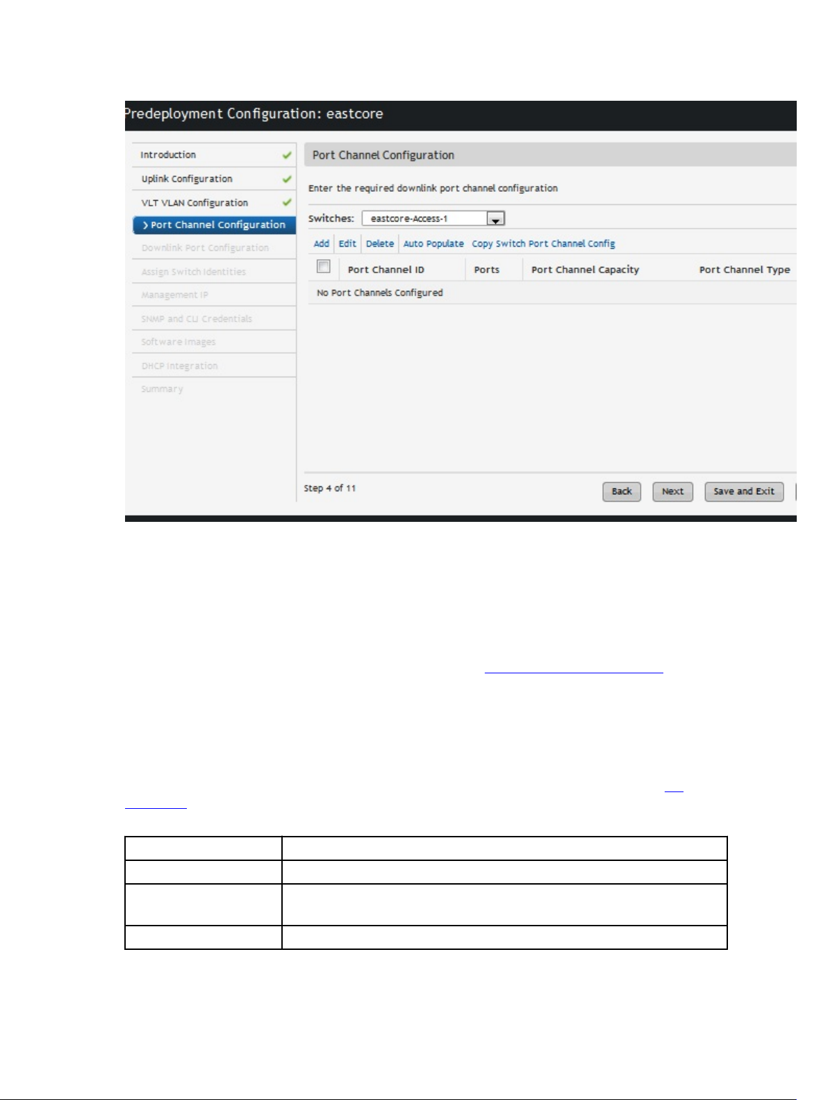
To create port channels to increase bandwidth and redundancy:
1. Navigate to the Network >
2. From the Deploy Fabric pull-down menu, select the Pre-deployment Configuration option.
3. Navigate to the Port Channel Configuration screen.
4. From the Switch pull-down menu, select a switch to apply the port channel configuration.
5. Click the Add link to manually add a port channel or the Auto populate link to automatically populate the port
channels. For more port channel configuration options, refer to the Port Channel Configuration Options table for
more information.
6. Click Next to go to the Downlink Port Configuration screen.
Fabric Name
> Configure and Deploy screen.
Pre-deployment – Step 1d: Downlink Port Configuration (Layer 2 VLT)
To add VLANs and associate ports on the different switches for a Layer 2 fabric, use the Downlink Port Configuration
screen. Once that is done you can copy switch VLAN or port VLAN configurations. You can be associate one or more
tagged VLANs with a port and for untagged VLAN only one is allowed. For information about Downlinks, see VLT
Terminology.
Table 19. Downlink Port Configuration Layer 2 Field Descriptions
Field Name Description
Configured VLANs Displays list of VLANs specified in the VLT VLAN Configuration screen.
Port Name Displays the port name.
This a
read only
Tagged VLANs Manual Entry:
field.
90
Page 91

Enter one or more VLANs to associate with the port.
Validation Criteria: The VLANs have to be from the Configured VLANs list and the
Untagged VLAN field should be empty.
Default: <Blank>
1. Select from the list (click on the icon next to the field entry)
2. Select one or more VLANs to be associated with the port.
Untagged VLANs Select a VLAN to associate with the port.
Validation Criteria: Tagged VLAN field should be empty.
Default: <Blank>
Table 20. Layer 2 Downlink Port Options
Option Description
Auto-fill Tagged Port For selected VLANs, sequential tagging is applied to the available ports and the number
of ports specified on a VLAN.
Auto-fill Untagged Port For selected VLANs, untagging is applied. Based on available ports, only one port per
VLAN is associated.
Note: The number of Port/VLAN Port option is disable on the Autofill Tagged/Untagged
Port screen.
Copy Switch VLAN Config Copies the VLAN association from the current switch to other switch (es) in the fabric.
Copy VLAN Port Config Copies the VLAN association from a selected port to other port (s) within a switch.
Port-VlAN Association Maps the physical port to the VLAN ID. For example, maps 1 port to multiple VLANs.
VLAN-Port Association Maps the VLAN ID to physical port interfaces. For example, maps 1 VLAN to multiple
ports.
Copy VLAN Tagged Port
Config
Copies the VLAN tagged port configuration from a selected port to other port (s) within
a switch.
To configure downlink ports on the access switches:
1. Navigate to the Network >
Fabric Name
> Configure and Deploy screen.
2. From the Deploy Fabric pull-down menu, select the Pre-deployment Configuration option.
3. Navigate to the Layer 2 VLT Downlink Port Configuration screen.
91
Page 92
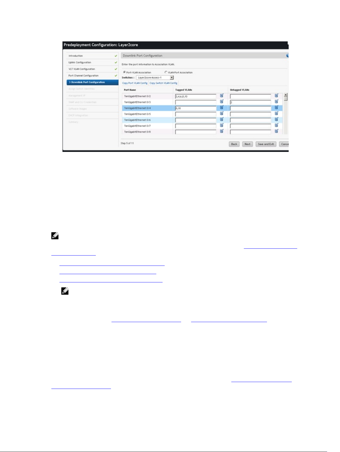
Figure 38. Downlink Port Configuration for Layer 2
4. From the Switches pull-down menu, select an access switch.
5. In the Tagged VLANs, click on the icon next and enter one or more VLANs to be associated with the port.
6. When you are finished, click the Next button to go to the Assign Network Identities screen.
Protocol Configuration — Layer 3 Distributed Core Fabric: Step 1
To configure the pre-deployment protocol configuration for a Layer 3 distributed core fabric, complete the following
tasks.
NOTE:
Before you begin, review the pre-deployment workflow for a Layer 3 distributed core fabric at Using the Pre-deployment
Configuration Wizard.
• Pre-deployment – Step 1a: Fabric link Configuration
• Pre-deployment – Step 1b: Uplink Configuration
• Pre-deployment – Step 1c: Downlink Configuration
NOTE: For pre-deployment, the Layer 2 VLT, Layer 3 Distributed Core, and Layer 3 with Resiliency (Routed VLT)
fabrics use the same pre-deployment configuration screens from step 2 through step 7.
Pre-deployment – Step 1a: Fabric link Configuration
Before you begin, review the Using the Pre-Deployment Wizard and Pre-deployment Wizard: Introduction sections.
To configure the links that connect the leaves and spines for a Layer 3 distributed core fabric or the links that connect
the core, access, and aggregation switches for a Layer 3 with Resiliency (Routed VLT) fabric using the OSPF routing
protocol, use the Fabric link Configuration screen. The Port Bandwidth (a read-only field) is automatically determined by
the selected fabric type and fabric oversubscription ratio. To automate the pre-deployment process, AFM automatically
populates the starting IP address range/prefix, loop IP address/prefix based on the fabric design, and sets the area ID
for OSPF to 0. Review these settings. You can modify the IP address range and loopback address. The start prefix for
both types of addresses must be from 8 to 29 and the loopback prefix from 8 to 26.
For information about how to configure a Layer 2 VLT Fabric Interlink Configuration, see Pre-deployment – Step 1: VLT
Fabric Interlink Configuration
92
Page 93

Important: The area ID for the interconnect link must not be the same as the area ID for the uplink.
To configure the Fabric Link Configuration for a Layer 3 distributed core fabric:
1. Navigate to the Network >
2. From the Deploy Fabric pull-down menu, select the Pre-Deployment Configuration option.
The Introduction screen displays.
3. Review the Introduction screen and gather the useful information to prepare your fabric for deployment.
4. Click the Next button.
The Fabric Link Configuration screen displays.
5. In the Start IP Address Range/Prefix area, enter the starting IP address and prefix.
The prefix must be from 8 to 29.
6. In the Loopback IP Address Range/Prefix area, enter the loopback address range and prefix.
The prefix must be from 8 to 26.
7. In the Area ID field, use the default setting of 0 or enter the area ID.
The area ID is a value from 0 and 65535. The uplinks or interlinks must be in area 0 for OSPF.
Fabric Name
> Configure and Deploy screen.
Pre-deployment – Step 1b: Uplink Configuration
The Uplink Configuration screen for a Layer 3 and Layer 3 with Resiliency (Routed VLT) fabric displays the port
bandwidth and the number of specified ports (read-only fields) entered on the Bandwidth and Port Count screen. To
configure the uplink protocol for the edge port uplinks to the WAN, use the Uplink Configuration screen. For information
about for a uplinks for a Layer 3 distributed core fabric, see Distributed Core Terminology.
NOTE: When the Open Shortest Path First (OSPF) is selected for both uplinks and interlinks, one of uplinks or
interlinks must be in area 0.
To configure the uplink protocol for the edge port uplinks to the WAN for a Layer 3 distributed core fabric:
1. Navigate to the Network >
2. From the Deploy Fabric pull-down menu, select the Pre-deployment Configuration option.
3. Navigate to the Uplink Configuration screen.
4. In the Protocol Settings, select a routing protocol (OSPF, IBGP, or eBGP) for the edge port uplinks. The number of
uplinks is specified in the Bandwidth and Port Count screen.
AFM automatically populates the range of IP addresses that belong to the /30 subnet.
a) For OSPF, for each specified uplink, enter the local IP address, remote neighbor IP address, and area ID. A valid
area ID area is from 0 to 65535.
b) For iBGP, for each specified uplink, enter the local IP address, remote neighbor IP address, local AS number.
For the AS number, enter a value from 1 to 4294967295.
c) For eBGP, for each specified uplink, enter the local IP, remote neighbor IP address, local AS number, and
remote AS number. For the AS number, enter a value from 1 to
5. Click Next to go the Downlink Configuration screen.
Fabric Name
> Configure and Deploy screen.
4294967295.
Pre-deployment – Step 1d : Downlink Configuration (Layer 3)
Downlinks are edge port links which connect to servers, switches, or ToRs. When you enable the ToR configuration, the
leaves function as a ToR. When you disable the ToR configuration, the leaves function as a switch. The port bandwidth
for the downlinks is 1 Gb, 10 Gb, or 40 Gb (a read-only field). For more information about downlinks, see Distributed Core
Terminology and VLT Terminology.
93
Page 94

Figure 39. Downlink Configuration for Layer 3 Distributed Core Fabric
To configure the downlinks for a Layer 3 distributed core fabric:
1. Navigate to the Network >
2. From the Deploy Fabric pull-down menu, select the Pre-deployment Configuration option.
3. Navigate to the Downlink Configuration screen.
4. To have the leaves act as a ToR, select the Specify Leaf as ToR option.
5. Manually configure the downlinks, or to automatically generate the downlink configuration, check the Generate
Downlink Configuration option.
6. In the Start IP Address Range/Prefix field, enter the starting IP address and prefix.
Enter a valid IP address and a prefix from 8 to 23.
7. In the Number of ports per port channel, enter the number of ports assigned to a port channel for a particular VLAN
ID.
Range: from 1 to 16.
8. In the Starting VLAN ID field, enter a starting VLAN ID.
Range: from 2 and 4094.
9. From the Protocol Profile pull-down menu, when the leaves are acting as a leaf switch (the switches are directly
connected to the server), select the Downlink VLAN and VRRP and LAG protocol setting. The default setting is
Downlink VLAN.
10. Click Next to go the Assign Switch Identities screen.
Fabric Name
> Configure and Deploy screen.
Protocol Configuration — Layer 3 with Resiliency (Routed VLT) : Step 1
To configure the pre-deployment protocol configuration for a Layer 3 with Resiliency (Routed VLT) , complete the
following tasks:
NOTE: The Layer 2 VLT, Layer 3 Distributed Core, and Layer 3 with Resiliency (Routed VLT) fabrics use the same
pre-deployment configuration screens from step 2 through step 7. Before you begin, review the pre-deployment
workflow at Using the Pre-deployment Configuration Wizard.
1. Pre-deployment – Step 1a: Fabric Link Configuration
2. Pre-deployment – Step 1b: Uplink Configuration
94
Page 95

3. Pre-deployment - Step 1c: VLT VLAN Configuration
4. Pre-deployment – Step 1d: Port Channel Configuration
5. Pre-deployment – Step 1e: Downlink Port Configuration
Pre-deployment – Step 1a: Fabric link Configuration
Before you begin, review the Using the Pre-Deployment Wizard and Pre-deployment Wizard: Introduction sections.
To configure the links that connect the leaves and spines for a Layer 3 distributed core fabric or the links that connect
the core, access, and aggregation switches for a Layer 3 with Resiliency (Routed VLT) fabric using the OSPF routing
protocol, use the Fabric link Configuration screen. The Port Bandwidth (a read-only field) is automatically determined by
the selected fabric type and fabric oversubscription ratio. To automate the pre-deployment process, AFM automatically
populates the starting IP address range/prefix, loop IP address/prefix based on the fabric design, and sets the area ID
for OSPF to 0. Review these settings. You can modify the IP address range and loopback address. The start prefix for
both types of addresses must be from 8 to 29 and the loopback prefix from 8 to 26.
For information about how to configure a Layer 2 VLT Fabric Interlink Configuration, see Pre-deployment – Step 1: VLT
Fabric Interlink Configuration
Important: The area ID for the interconnect link must not be the same as the area ID for the uplink.
To configure the Fabric Link Configuration for a Layer 3 distributed core fabric:
1. Navigate to the Network >
2. From the Deploy Fabric pull-down menu, select the Pre-Deployment Configuration option.
The Introduction screen displays.
3. Review the Introduction screen and gather the useful information to prepare your fabric for deployment.
4. Click the Next button.
The Fabric Link Configuration screen displays.
5. In the Start IP Address Range/Prefix area, enter the starting IP address and prefix.
The prefix must be from 8 to 29.
6. In the Loopback IP Address Range/Prefix area, enter the loopback address range and prefix.
The prefix must be from 8 to 26.
7. In the Area ID field, use the default setting of 0 or enter the area ID.
The area ID is a value from 0 and 65535. The uplinks or interlinks must be in area 0 for OSPF.
Fabric Name
> Configure and Deploy screen.
Pre-deployment – Step 1b: Uplink Configuration
The Uplink Configuration screen for a Layer 3 and Layer 3 with Resiliency (Routed VLT) fabric displays the port
bandwidth and the number of specified ports (read-only fields) entered on the Bandwidth and Port Count screen. To
configure the uplink protocol for the edge port uplinks to the WAN, use the Uplink Configuration screen. For information
about for a uplinks for a Layer 3 distributed core fabric, see Distributed Core Terminology.
NOTE: When the Open Shortest Path First (OSPF) is selected for both uplinks and interlinks, one of uplinks or
interlinks must be in area 0.
To configure the uplink protocol for the edge port uplinks to the WAN for a Layer 3 distributed core fabric:
1. Navigate to the Network >
2. From the Deploy Fabric pull-down menu, select the Pre-deployment Configuration option.
3. Navigate to the Uplink Configuration screen.
Fabric Name
> Configure and Deploy screen.
95
Page 96

4. In the Protocol Settings, select a routing protocol (OSPF, IBGP, or eBGP) for the edge port uplinks. The number of
uplinks is specified in the Bandwidth and Port Count screen.
AFM automatically populates the range of IP addresses that belong to the /30 subnet.
a) For OSPF, for each specified uplink, enter the local IP address, remote neighbor IP address, and area ID. A valid
area ID area is from 0 to 65535.
b) For iBGP, for each specified uplink, enter the local IP address, remote neighbor IP address, local AS number.
For the AS number, enter a value from 1 to 4294967295.
c) For eBGP, for each specified uplink, enter the local IP, remote neighbor IP address, local AS number, and
remote AS number. For the AS number, enter a value from 1 to 4294967295.
5. Click Next to go the Downlink Configuration screen.
Pre-deployment – Step 1c: VLT VLAN Configuration for Layer 3 with Resiliency Fabric (Routed VLT)
Use this screen to configure the VLT VLAN configuration for a Layer 3 with Resiliency (Routed VLT) fabric.
This section contains the following topics:
• VLT VLAN Layer 3 with Resiliency (Routed VLT)
• Advanced VLAN IP Configuration
Table 21. VLT VLAN Configuration Options for Layer 3 with Resiliency (Routed VLT) Fabirc
VLAN Option Description
Add VLAN Creates a VLAN row.
Add VLAN Range Automates VLAN creation and automatically populates IP addresses.
Enter the following VLAN information:
• Starting VLAN ID — Enter the Starting VLAN ID. Range: 2 to 4094
• Number of VLANs — Enter the Number of VLANs.
• VLAN Increment. If you do not specify an increment, the VLAN is incremented by 1.
• Start Subnet IP Address/Prefix: — IP range to automatically populate VLAN IP
addresses. IP addresses include primary, secondary peer VLAN, and VRRP IP.
NOTE: You must check the VLAN and VRRP Configuration option to view this
option.
VLAN and VRRP
Configuration (for a Layer 3
fabric for Resiliency (Routed
VLT)
Autofill VLAN IP
(For Enable Layer 3 Protocol
in Access Switches option
only)
Delete VLAN Removes selected VLAN row.
Edit VLAN Edit VLAN ID, primary IP address, and secondary IP address.
VLAN ID Enter the VLAN ID.
Configures IP address with VRRP protocol. When the VLAN and VRRP Configuration
option is selected the following fields are displayed.
• Primary IP
• Secondary IP
• Virtual IP
Enter the starting subnet IP address/prefix for the range of selected VLANS. The IP
addresses are automatically populated.
Range: 2 to 4094
96
Page 97

Default: <Blank>
Primary IP Enter the primary IP address. The prefix is auto-populated.
Validation Criteria for Primary IP: Valid IP
Prefix Range: from 8 to 29
Default Primary IP: <Blank>
Default Prefix: 24
Secondary IP Enter the secondary IP address. The prefix is auto-populated.
Address for Secondary IP: Valid IP address
Prefix range: from 8 to 29
Default Secondary IP: <Blank>
Default Prefix: 24
VLT VLAN Configuration for Layer 3 with Resiliency (Routed VLT)
Figure 40. Layer 3 with Resiliency (Routed VLT) Deployment Topology
The following screen shot displays a VLT VLAN Configuration screen without selecting the Enable Layer 3 protocol in
Access Switches option. By default the VLT VLAN screen for Layer 3 with Resiliency (Routed VLT) requires that you
enter the primary and secondary IP address for the VLAN ID as show in the following screen shot.
97
Page 98

Figure 41. VLT VLAN Configuration Without Using the Enable Layer 3 Protocol in Access Switches Option
The following screen shot displays a VLT VLAN Configuration screen using the Enable Layer 3 protocol in Access
Switches option. To have the topology for a Layer 3 with Resiliency (Routed VLT) support both access and aggregation
devices, select the Enable Layer 3 protocol in Access Switches option. When you use this option, provide the network IP
address range using the Add VLAN Range link. The IP addresses are assigned to all the access and aggregation
switches.
Figure 42. Layer 3 with Resiliency Using the Enable Layer 3 Protocol in Access Switches Option
The following screen shot displays the results after checking the Enable Layer Protocol in Access Switches option and
adding VLANs for a Layer 3 with Resiliency (Routed VLT) fabric.
98
Page 99

Figure 43. Adding VLANs and Enabling the Layer Protocol in Access Switches Option
To configure a VLT VLAN for a Layer 3 with Resiliency (Routed VLT) topology:
1. Navigate to the Network >
2. From the Deploy Fabric pull-down menu, select the Pre-deployment Configuration option.
3. Navigate to the VLT VLAN Configuration screen.
4. Check the Enable Layer 3 Protocol in Access Switches option.
5. Click the Add VLAN link.
The Add VLAN Window is displayed.
6. Click the Add VLAN Range link and then specify the VLAN range to assign the IP addresses to the switches for the
Layer 3 with Resiliency (Routed VLT) fabric.
7. Click the Next button to view the Port Channel Configuration screen.
Fabric Name
> Configure and Deploy screen.
Advanced VLAN IP Configuration
After completing the pre-deployment process, you can later modify the VLT VLAN configuration for Layer 3 with
Resiliency (Routed VLT) topology using the Advanced VLAN IP Configuration option at the Network >
Configure and Deploy screen.
Fabric > Switch
>
99
Page 100

Figure 44. Advanced VLAN IP Configuration Option
Pre-deployment – Step 1d: Port Channel Configuration (Layer 3 — Routed VLT)
Use this screen to optionally add, edit, delete, and automatically populate the port channel configuration for Layer 3 with
Resiliency (Routed VLT) fabric. Once you add a port channel configuration you can copy it.
Table 22. Port Channel Configuration Options
Field Name Description
Add Enter port channel information and enable LACP.
Auto Populate Enter port channel information to automatically assign port channels to switches in
the fabric and enable LACP.
• Number of Ports per Port Channel
• Start Port Channel ID
• Number of Port Channel
• Port Channel Increment
• Enable LACP (optional)
Copy Switch Port Channel
Configuration
Delete Deletes a selected port channel configuration.
Edit Enter the port channel configuration.
100
Copies over switch port channel configuration from another switch. You first create a
port channel configuration and then you can copy over to another switch.
 Loading...