

Page 1

Active Fabric Controller (AFC) Deployment
Guide
Page 2

Notes, Cautions, and Warnings
NOTE: A NOTE indicates important information that helps you make better use of your computer.
CAUTION: A CAUTION indicates either potential damage to hardware or loss of data and tells you
how to avoid the problem.
WARNING: A WARNING indicates a potential for property damage, personal injury, or death.
Copyright © 2014 Dell Inc. All rights reserved. This product is protected by U.S. and international copyright and
intellectual property laws. Dell™ and the Dell logo are trademarks of Dell Inc. in the United States and/or other
jurisdictions. All other marks and names mentioned herein may be trademarks of their respective companies.
2014–04
Rev. A00
Page 3

Contents
1 Introduction................................................................................................................5
System Requirements............................................................................................................................5
Recommended Requirements .............................................................................................................5
Pre-Installation Procedure....................................................................................................................6
Installing a Single-Server Controller ....................................................................................................6
Installing a Dual-Server (Active/Standby) Controller........................................................................... 7
2 Install AFC using OVF...............................................................................................9
Installing the Software...........................................................................................................................9
Deploying AFC — OVF using vSphere................................................................................................ 10
Configuring the AFC VM......................................................................................................................13
AFC Main Menu....................................................................................................................................15
Show AFC Status..................................................................................................................................16
Configuring the AFC Active Node.......................................................................................................17
Configuring the AFC Standby Node................................................................................................... 18
Configuring Logs to the Database......................................................................................................19
Upgrading AFC.....................................................................................................................................19
Maintaining the VM using OVF............................................................................................................19
Installing BMP......................................................................................................................................20
Upgrading the Switch Firmware......................................................................................................... 21
3 Install AFC using RPM............................................................................................23
Preparing the Server for AFC RPM Installation ..................................................................................23
Installing AFC using RPM.................................................................................................................... 24
....................................................................................................................................................... 24
Installing the AFC Active Node..................................................................................................... 24
Installing the AFC Standby Node.................................................................................................. 25
Uninstalling AFC.................................................................................................................................. 25
4 Deploying AFC.........................................................................................................27
Installing the Dell OpenStack ML2 Mechanism Driver.......................................................................27
Configuring BMP on the Switch......................................................................................................... 27
Connect to Legacy Networks.............................................................................................................28
OpenStack Legacy Configuration................................................................................................ 28
Configure the Uplinks................................................................................................................... 28
Enabling Active Fabric.........................................................................................................................29
Step 1 — Weaving the Fabric.........................................................................................................29
Step 2 — Enabling the Fabric .......................................................................................................30
Page 4

Step 3 — Enabling the Controllers............................................................................................... 30
Step 4 — Configuring the Provider Networks .............................................................................30
Step 5 — Enabling the Tenant Workload Configuration using OpenStack................................ 30
Step 6 — Enabling Server High Availability...................................................................................30
Page 5

1
Introduction
This document guides you through the installation, setup, and deployment of the Active Fabric Controller
(AFC) software on a single server or on two servers in an active-standby configuration.
NOTE: You can install the software on a single server. For resiliency, Dell Networking recommends
configuring a dual-server setup for high availability (HA).
Install the software using the route processor module (RPM) or the open virtualization format (OVF)
image. Installation scripts, including RPM-based scripts for components, such as the database service,
software controller, and web-based graphical user interface (GUI) are used during installation.
System Requirements
Each server can be a virtual machine (VM) or a physical machine. The server or virtual machine
requirements are:
• CPU — 2.4 GHz, Intel Xeon CPU or equivalent. For optimal performance, Dell Networking
recommends a four-core as a minimum.
• Memory — 8 GB
• Disk space — 30 GB
• Network Interface — 1x1 GbE
• CentOS 6.4, 64–bit (for RPM installation)
• ESX 4.x or 5.x server (for OVF installation)
• MongoDB
• Link layer discovery protocol (LLDP) enabled on all hosts and servers
Recommended Requirements
The following components are not required to run the software, but are recommended to provide
additional capabilities:
• Dell OpenFlow-compatible switches
• A second server for HA configuration to provide resiliency
• Enabling bare metal provisioning (BMP) updates the firmware on the switches automatically. To
enable BMP, the switches and the controller must be in the same Layer2 (L2) network. Also, the
location of the image and the primary boot location must be the same.
Introduction
5
Page 6

Pre-Installation Procedure
Before installing the software, perform the following pre-installation steps:
1. Prepare the infrastructure networks.
Infrastructure networks support management of the physical infrastructure by the software. A typical
OpenStack environment requires two infrastructure networks: a storage network and an OOB
network. You can implement these networks as two separate physical L2 networks or as virtual local
area networks (VLANs) on the same physical L2 network. Typically, servers in an OpenStack
environment connect to both infrastructure networks.
2. Prepare the out-of-band (OOB) OpenFlow management network.
The controller communicates with the OpenFlow-enabled switches over a Layer3 (L3) IP network,
known as the OpenFlow management network. This is typically done using an OOB network.
Connect the management port of each OpenFlow-enabled switch to this network and ensure that
the server used to install the software is physically connected to this network.
3. Prepare the OpenFlow-enabled switches.
The software supports Dell Networking S4810, S4820T, S6000, and MXL switches. The Dell
Networking operating system (OS) version on the switch must be 9.4(0.0) or later. For OpenFlow
requirements, refer to the SDN Deployment Guide on the Dell Networking documentation website.
Installing a Single-Server Controller
You can install the software on a single server; however, this type of deployment does not provide the
resiliency of a dual-server configured for HA. As shown in the following example, a single-server
deployment:
• requires you to deploy all AFC components on a single VM or server
• allows you to deploy associated software on additional VMs or servers as needed
6
Introduction
Page 7
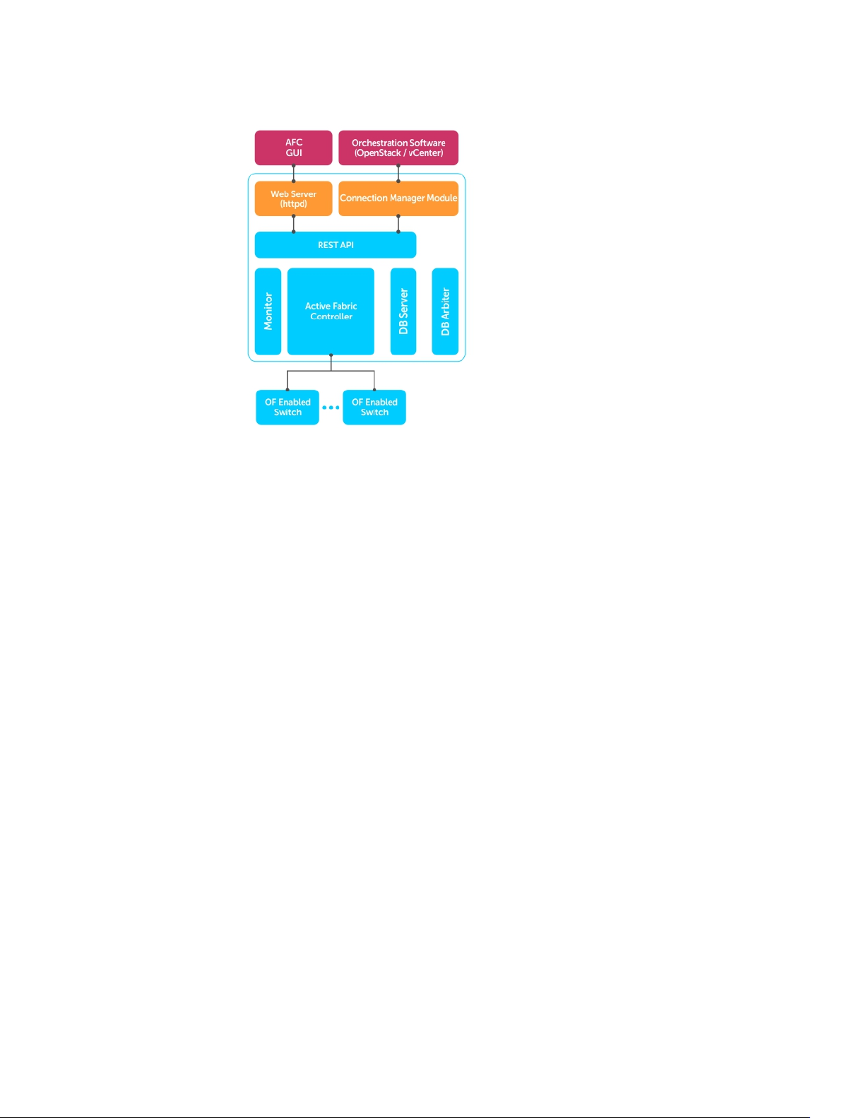
Figure 1. Single-Server Deployment
Installing a Dual-Server (Active/Standby) Controller
Dell Networking recommends a dual-server controller for resiliency. As shown in the following example,
a dual-server deployment:
• Requires you to deploy all AFC components on a single VM or server
• Allows you to deploy associated software on additional VMs or servers as needed
• Provides an Active-Standby configuration using a single VIP address
Introduction
7
Page 8
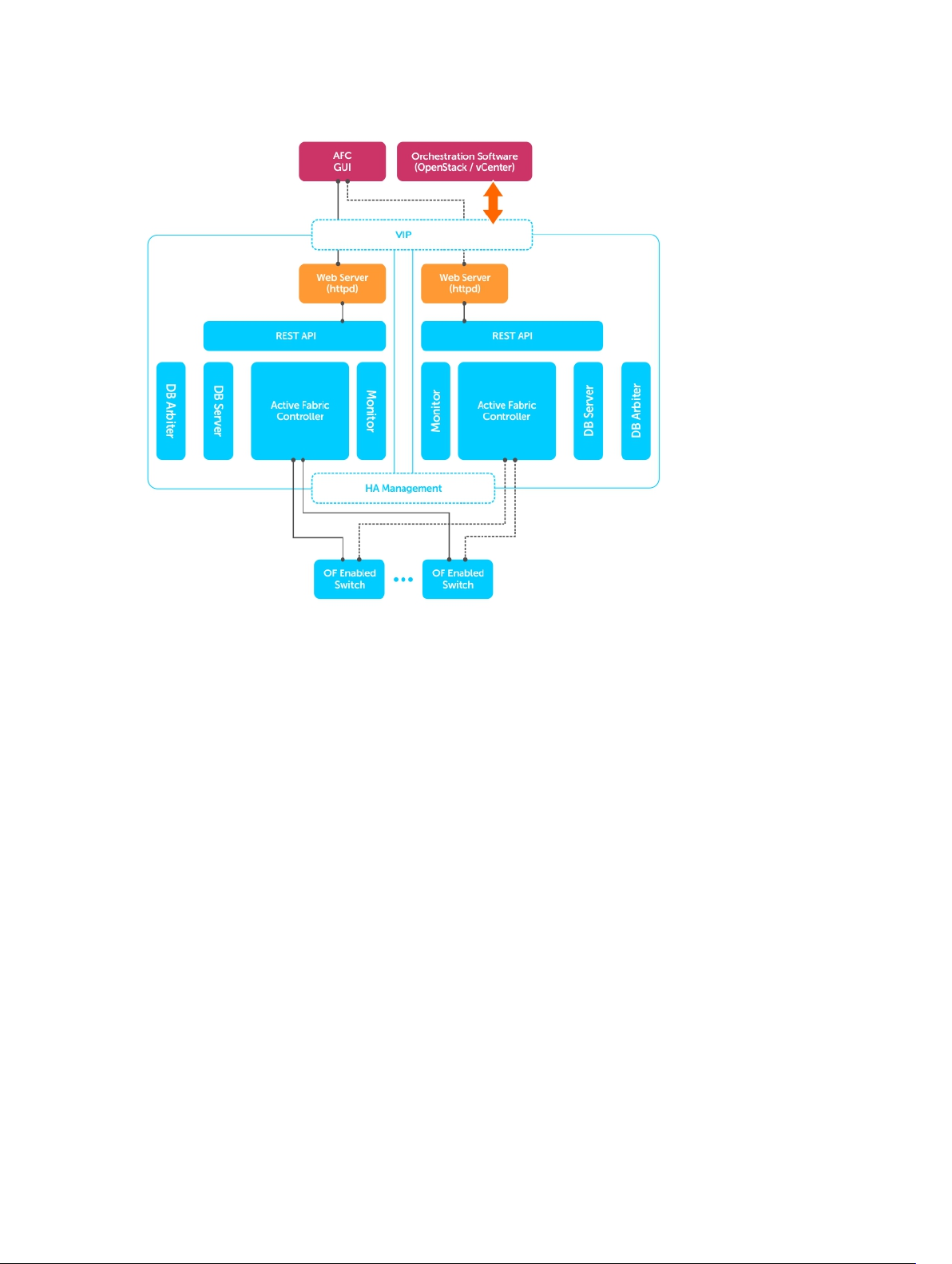
Figure 2. Installing a Dual-Server Controller
8
Introduction
Page 9

Install AFC using OVF
The following sections describe how to install AFC using OVF.
You can install the software on a VM running on a hypervisor or on a physical machine.
Installing AFC using OVF loads the software image and configure the system to interconnect with your
hypervisor environment.
NOTE: Regardless of installation type or deployment scenario, you must enable LLDP on all servers
and hosts.
Installing the Software
The OVF includes all software and services required to run AFC, including the following software
components:
• Controller
• Web server
• GUI
• Monitor
• Database server
Deploy the OVF on an ESX 4.x or ESX 5.x server. The software is pre-installed in the OVF image.
2
Install AFC using OVF
9
Page 10

Deploying AFC — OVF using vSphere
To deploy OVF, follow these steps.
1. Deploy the OVF template.
Select File then Deploy OVF Template.... Select Next.
Figure 3. Deploy the OVF Template
2. Select the source location.
Use the Browse button to select the OVF file. Select Next.
Figure 4. Select the Source Location
10
Install AFC using OVF
Page 11

3. The OVF Template Details page displays.
If the template details are correct, select Next.
If the template details are incorrect, select Back and re-enter your selections.
Figure 5. Template Details
4. Rename your VM and choose your inventory location.
(Optional) In the Name: field, enter the name of your VM.
In the Inventory Location: field, select your inventory location. Select Next.
Figure 6. Template Name and Location Options
5. Select the storage location for your VM files. Select Next.
Figure 7. Template Storage
Install AFC using OVF
11
Page 12

6. Select the virtual disk format.
There are three types of disk format:
• Thick Provision Lazy Zeroed
• Thick Provision Eager Zeroed
• Thin Provision (Dell recommended)
Select Next.
Figure 8. Virtual Disk Formatting
7. Select the network map to use. Select Next.
Figure 9. Network Mapping
12
Install AFC using OVF
Page 13

8. Confirm your OVF selections.
Review the options shown in the Deployment settings: field.
If your deployment settings are correct, select Finish. Deploying OVF takes several minutes.
If your deployment settings are incorrect, select Back and re-enter your selections.
Figure 10. Ready to Complete
Configuring the AFC VM
To configure your virtual machine (VM), follow these steps.
1. Power on your VM from vSphere.
Right-click on your VM name and select Power then Power On.
Figure 11. Power On the VM
2. First time login: select the Console tab in vSphere and enter the AFC login.
The userID is superuser.
After you have successfully logged in for the first time, on the Console tab, press Enter to begin
configuring the VM.
Install AFC using OVF
13
Page 14

3. Select Device Configuration using the space bar key. Use the tab key to select Save&Quit.
To return to the previous screen, select Quit.
Figure 12. Device Configuration
4. Select eth0 using the space bar key to configure the IP address. Use the tab key to select Save.
To return to the previous screen, select Cancel.
Figure 13. Configure the IP Address
14
Install AFC using OVF
Page 15

5. Enter the following network configuration details to configure the newtwork. Use the tab key to
select OK.
• Name: enter eth0.
• Device: enter eth0.
• Static IP: enter the static IP address.
• Netmask: enter the netmask IP address.
• Default gateway IP: enter the default gateway IP address.
• Primary DNS Server: enter the primary DNS server IP address.
• Secondary DNS Server: enter the secondary DNS server IP address.
To return to the previous screen, select Cancel.
The system automatically reboots after saving this information.
Figure 14. Configure the Network
After your system reboots, use the same userID (superuser) to go to the AFC main menu. VSphere is no
longer required.
AFC Main Menu
The following shows the AFC Main Menu.
Figure 15. AFC Main Menu
• Show AFC Status: Displays the current AFC status for the controllers, database, and other software
components.
Install AFC using OVF
15
Page 16

• Change AFC superuser Password: Changes the AFC default administrative password. The password is
case sensitive.
• AFC Configuration: Displays the AFC configuration submenu.
– Active Node: Displays Active Node options.
– Standby Node: Displays Standby Node options.
• Logs Configuration: Displays the Logs configuration submenu.
– Logs to DB: Exports logs to the database.
– Edit log configuration: Edits log configuration information.
– Export logs: Exports the logs to the server.
• Start/Restart AFC: Starts or restarts AFC.
• AFC Software Upgrade: Upgrades the AFC software.
– AFC Software Download: Begins the AFC software upgrade process.
– Upgrade AFC Software: Selects the AFC software version to use.
• BMP Installation: Edits BMP configuration information.
– Switch Firmware Download: Downloading the latest BMP firmware.
– Modify BMP Switch Firmware: Editing existing BMP installation.
• Reboot Server: Restarts the server, VM, or operating system.
• Shutdown Server: Shuts down the server, VM, or operating system.
• Exit: Exits AFC.
Show AFC Status
To review the AFC status, follow this step.
After you complete IP configuration, the system automatically restarts.
16
Install AFC using OVF
Page 17

To log in to the AFC main menu, use the same userID (superuser).
1. Use the Up and Down arrow keys to select Show AFC Status. Press Enter.
The AFC system status displays.
Figure 16. Show AFC Status
2. Press Enter again to return to the main menu.
Figure 17. Show AFC Status Display
Configuring the AFC Active Node
Deploy the OVF and configure the IP address for an Active node installation.
To use Active node installation, first configure AFC.
NOTE: The database automatically configures in cluster for high availability (HA).
To configure AFC for active node installation and to review or change your virtual IP or multicast
configurations, follow these steps.
1. Enter 1 to select Active node installation. Press Enter.
The AFC Active Configurations screen displays.
2. Select Virtual IP Configuration to manage the Active node using a virtual IP (VIP) address. Press
Enter.
Using a virtual IP address eliminates a host’s dependency on an individual network interface.
Install AFC using OVF
17
Page 18

3. The Virtual IP Setting displays. If the virtual IP settings are correct, press Enter.
You can change the following settings on this page:
• SDNC VIP for this HA setup — select true or false.
• SDNC VIP’s base interface
• SDNC VIP’s alias interface
• SDNC VIP address
• SDNC VIP netmask
To return to the main menu, press Enter.
4. Select Multicast Configuration to review or change your settings. If the virtual IP settings are correct,
press Enter.
Use to Multicast to help you isolate one AFC configuration from another AFC configuration.
You can change the following settings on this page:
• Multicast IP address
• Multicast port
NOTE: The multicast IP address and port number must be unique across your AFC
configurations.
To return to the main menu, press Enter.
Configuring the AFC Standby Node
Deploy another OVF and configure the IP address for a Standby Node installation.
NOTE: Before you deploy an AFC Standby node, you must first configure the AFC Active node.
NOTE: The database automatically configures in cluster for high availability (HA).
To configure AFC for a standby node installation and to review or change your virtual IP or multicast
configurations, follow these steps.
1. Enter 2 to join an existing AFC. Press Enter.
The AFC Standby Configurations screen displays
2. Select Standby Configuration. Press Enter.
3. Enter the Active HA node IP address. Press Enter to start the Standby AFC node and database.
After you enter the Active node IP address, all the configuration files copy from the Active node. The
database configures as a Secondary node for HA.
18
Install AFC using OVF
Page 19

Configuring Logs to the Database
To log in to the database or edit or export logs, use the following steps.
1. Log in to the DB. Use the Up and Down arrows to select Logs to DB — Requires restart AFC to take
effect
to log in to the DB. Press Enter.
Logs to DB stores three levels of log information to the database — info, warn, and error.
The 5MB table can store up to 15K of log records.
2. Edit the log configuration. Use the Up and Down arrows to select Edit Log configurations —
Requires restart AFC to take effect to edit the log configuration. Press Enter.
You can assign the log levels as info, warn, error, debug, and trace.
You can assign a value for each of the log file sizes and specify how many log files to create.
3. Export Logs. Use the Up and Down arrows to select Export Logs to export the log configuration.
Enter.
Press
To export logs, enter the TFTP IP address and press Enter.
After you have configured AFC and the log configuration, you must restart the controller.
Upgrading AFC
To upgrade the AFC software, follow these steps.
1. Use the up or down arrow keys to select AFC Software Upgrade. Press Enter.
2. Use the up or down arrow keys to select AFC Software Download. Press Enter.
3. Enter the AFC software URL.
4. Enter your user name and password. The password is case sensitive.
5. Use the up or down arrow keys to select Upgrade AFC Software. Press Enter.
The AFC software versions that are available to install display.
6. Choose the AFC software upgrade you want to install.
Enter the number of the software version you wish to use, then press Enter.
The software automatically installs after you select the number.
Maintaining the VM using OVF
To change your superuser password, reboot the VM, or shutdown the menu, follow these steps.
1. Change your superuser password.
Enter the current superuser password, then press Enter.
Enter the new password, then press Enter.
The password is case sensitive.
2. Reboot your VM.
Press Enter to reboot the VM.
Install AFC using OVF
19
Page 20

3. Shut down the VM.
Press Enter to shut down the VM.
Installing BMP
To install, download and modify the switch firmware, following these steps.
1. Install BMP using the BMP Installation Menu. Use the Up and Down arrows to select BMP
Installation
2. Use the BMP setup wizard to configure your BMP installation. Use the SYSLOG server setup wizard to
configure your SYSLOG server.
Configure the following for the BMP setup wizard:
• Do you want to configure standby server in BMP? Input yes/no: — enter yes or no.
• Input the netmask — enter the netmask number.
• DHCP IP range from: — enter the DHCP IP range.
Configure the following for the SYSLOG server setup wizard:
• Do you want to configure Syslog server in BMP? Input yes/no: — enter yes or no.
– If yes, provide the ip address for the syslog server.
• SWITCH AUTHENTICATION Configure the following for switch authentication:
. Press Enter.
NOTE: You must have a minimum of four IP addresses in the given DHCP IP range.
– 1. RADIUS AUTHENTICATION
– 2. TACACS+
– 3. NO AUTHENTICATION
Pick one from the above options (1\2\3).
To exit from the BMP Installation page, use the Up and Down arrows to select Exit. Press Enter.
20
Install AFC using OVF
Page 21

Upgrading the Switch Firmware
To upgrade the switch firmware, following these steps.
1. Download to the latest switch firmware. Use the Up and Down arrows to select Switch Firmware
Download
Enter 1, 2, 3 or 4 from the following options:
• 1 — MXL
• 2 — S4810
• 3 — S4820T
• 4 — S6000
Enter the URL location.
(Optional) enter a user name and password. The password is case sensitive.
Select Enter to download the switch firmware.
After you upgrade the switch firmware, you must reload the switch for the upgrade to start.
2. Select the switch firmware to upgrade.
Enter 1 or 2 to select the switch firmware to upgrade. For example:
• 1: DELL-SE-1–0–0–1862.bin
• 2: DELL-SE-1–0–0–2112.bin
Select Enter to upgrade the switch firmware.
. Press Enter.
To exit from the BMP Installation page, use the Up and Down arrows to select Exit. Press Enter.
Install AFC using OVF
21
Page 22

22
Page 23

3
Install AFC using RPM
The following sections describe how to install AFC using the route processor module (RPM).
You can install the software on a VM running on a hypervisor or on a physical machine.
Installing AFC using RPM create a new VM disk image and install CentOS 6.4 64–bit with all required
packages and system setup. To install on a physical machine, install CentOS 6.4 64–bit with all required
packages and system setup. For more information, refer to Installing Software using RPM.
NOTE: Regardless of installation type or deployment scenario, you must enable LLDP on all servers
and hosts.
Preparing the Server for AFC RPM Installation
AFC requires CentOS 6.4 64–bit (x86_64) server distribution, along with the following packages.
• mongo-10gen-2.2.3–mongodb_1.x86_64.rpm
• mongo-10gen-server-2.2.3–mongodb_1.x86_64.rpm
• install_afc.py
• uninstall_afc.py
• controller-server-0.9.0–#.x86_64.rpm
NOTE: # represents the latest build number.
NOTE: If your system does not meet the software requirements, the software displays an error or
warning message.
1. Prepare the system’s IP network by setting up the AFC’s IP address.
# vim /etc/hosts /etc/sysconfig/network /etc/sysconfig/network-scripts/
ifcfg-eth?
2. Disable UDEV for eth* by deleting eth* from the device name whitelist and removing any
SUBSYSTEM= entries containing eth*.
# vim /lib/udev/rules.d/*-persistent-net-generator.rules /etc/udev/
rules.d/*-persistent-net.rules
3. Install Apache HTTPD with PHP.
# use ‘sudo yum install httpd php php-common’
4. Install Java OpenJDK.
# use ‘sudo yum install java-1.6.0’
5. Install ARP.
# use ‘sudo yum install iputils’
6. Install SSHD.
# use ‘sudo yum install openssh-server’
Install AFC using RPM
23
Page 24

7. Install the following daemons:
• dhcpd
• xinetd
• in.tftpd
# use ‘sudo yum install dhcp xinetd tftp-server’
8. Reboot the system after you complete the package configuration.
Installing AFC using RPM
After placing the packages in the working directory, run the install_afc.py file. You are prompted to
provide any missing configuration values.
NOTE: During installation, you can ignore service stopping failures but do not ignore service starting
failures. If a starting failure occurs, verify that all pre-installation steps have been completed.
The install_afc.py install file prepares the system environment and required software packages for
software installation. It also deploys the default configuration files and settings. When you run
setup_afc.sh on the single-node controller or install_afc.py on the second node, the default
configuration settings are overwritten with the applicable configuration settings, including the BMP
configuration. For more information about BMP configuration, refer to
Configuring BMP on the Switch.
Installing the AFC Active Node
Deploy the RPM and configure the IP address for an Active node installation.
To use Active node installation, first configure AFC.
NOTE: The database automatically configures in cluster for high availability (HA).
To configure AFC for active node installation and to review or change your virtual IP or multicast
configurations, follow these steps.
1. Complete all the pre-installation steps, including preparing a physical or VM for the software
installation, as well as preparing the other network elements.
2. Run the install_afc.py install file on the single server.
For more information, refer to Running install_afc.ph in the following section.
3. Run the setup_afc.sh install file on the single server.
For more information, refer to Running setup_afc.sh in the following section.
4. If you installed BMP, reload all the switches in the fabric in BMP mode.
Running install_afc.py
1. Enter 1 to install the software in a single-server deployment or to install the software on the first
server used for a dual-server high-availability (HA) configuration.
2. Enter 1 to install or upgrade the software on the server.
3. Enter y to confirm the installation to the server.
4. Run the setup_afc.sh file to continue the installation.
24
Install AFC using RPM
Page 25

Running setup_afc.sh
NOTE: When you run the setup_afc.sh file, the software disables any current HA configurations.
1. To use a single-server without HA, enter false for Enable SDNC VIP for this HA setup.
2. If prompted, enter the multicast IP address and user plane (UP) port number. The multicast IP address
and port number must be unique. If you have a standby-server configuration, the servers must have
the same multicast address. You cannot use this address in other HA groups.
3. To enable BMP, enter true for Enable BMP Server. To disable BMP, enter false.
4. Press the Enter key to restart.
Installing the AFC Standby Node
Deploy another RPM and configure the IP address for a Standby Node installation.
NOTE: Before you deploy an AFC Standby node, you must first configure the AFC Active node.
NOTE: The database automatically configures in cluster for high availability (HA).
To configure AFC for a standby node installation and to review or change your virtual IP or multicast
configurations, follow these steps.
Pre-Installation Process
To use a second server in a HA configuration, perform the following steps:
1. Prepare two physical machines for software installation by completing all the steps in the
Prerequisites section in Installing Software using RPM as well as any associated equipment or
environments.
2. Run install_afc.py on the first server to start a new HA configuration. Refer to Running
install_afc.py in Installation for Single-Server Controller.
3. Run setup_afc.sh on the first server. Refer to Running setup_afc.sh in Installation for Single-
Server Controller.
4. Run install_afc.py on the second server to join an existing HA configuration. Refer to Running
install_afc.py on a Second Server.
5. Reload both switches in BMP mode.
Running install_afc.py on a Second Server
1. Enter 2 to install the software on the second server and join the existing HA configuration.
2. Enter 1 to install the software on the server RPM, then enter y to confirm the installation.
3. Enter the IP address of the primary HA server, then enter y to confirm the HA configuration.
Uninstalling AFC
To uninstall the AFC software:
1. Run the uninstall_afc.py file.
2. Enter y to confirm the uninstallation of the software.
3. Enter y to confirm the uninstallation of the database server.
4. Enter y to remove all associated resource directories and logs.
Install AFC using RPM
25
Page 26

5. Enter y to remove all database data and cluster configurations.
26
Install AFC using RPM
Page 27

4
Deploying AFC
The following sections describe deploying AFC.
Installing the Dell OpenStack ML2 Mechanism Driver
For more information, refer to the README.md for the ML2 Mechanism Driver at the following link:
https://github.com/accessfabric/dellmech
Configuring BMP on the Switch
BMP detects the software image to determine if an update is required. To enable BMP interoperability
with the software, dynamic host configuration protocol (DHCP) settings and startup trivial file transfer
protocol (TFTP) configuration settings are optimally configured.
NOTE: To enable BMP, the switches and the controller must be in the same L2 network. Also, the
image loading location drive and the primary boot location must be the same.
BMP is enabled or disabled based on current settings. To configure BMP, enable it manually. When you
install the active controller, enter the IP address of the standby controller. For more information about
BMP, refer to the
SDN Deployment Guide.
BMP chapter in the platform-specific Dell Networking OS Configuration Guide and the
If the software is upgraded, reinstalled, or the following settings are changed, you must reconfigure the
applicable configuration settings.
• Management network or IP network for nodes
• VMs are migrated to a different hypervisor with a different management network
• New deployment scenario (Single-server to dual-server or dual-server to single-server)
• Reset of database contents
• Switch firmware upgrade
• Configuration values
• Enabling or disabling features
If you have not manually configured the switches in the fabric, BMP is automatically enabled to update
the firmware and change the necessary configuration values. If you have manually configured the
switches in the fabric, Dell Networking recommends backing up the current configuration before
enabling BMP. To back up the current configuration, use the copy running-config flash://
initial_config
After you set up the switches and controller, use the reload-type jump-start command to enable
BMP in Privilege mode on any switches that are NOT already OpenFlow enabled.
After you set up the switches and controller, use the reload-type bmp command to enable BMP in
Configure mode on any switches that are already OpenFlow enabled.
Deploying AFC
command.
27
Page 28

Connect to Legacy Networks
The server fabric edge ports connect to the legacy switches running traditional L2 and L3 protocols.
Regardless of deployment mode, legacy switches cannot use L3 routing in the server fabric. All L2 VLANs
that you configure on the legacy switch must also be configured on the server fabric. The controller is
notified of the VLANs through the north-bound application programming interface (API). Fabric edge
ports that connect to legacy switches are considered uplink ports.
The following lists the requirements for legacy networks to connect to the server fabric:
• You can open Active Fabric in either End Host mode or as a transient logical switch.
• In End Host mode, ingress traffic on uplink ports is not forwarded or flooded back to other uplink
ports.
• End Host mode requires that you connect the legacy switch to the Active Fabric in VLT fashion (you
do not need to enable the VLT protocol in the legacy switch).
• If you operate the Active Fabric as a single logical switch, ingress traffic on uplink ports can be flooded
or forwarded to other uplink ports.
OpenStack Legacy Configuration
Unlike a legacy router or switch connectivity through the uplink, for an OpenStack configuration, the
northbound traffic enters through OpenStack router running on the server that routes the traffic through
another L3 interface. The routed traffic is sent on an internal VLAN to the legacy router or wide-area
network (WAN) switch using the server fabric.
Using the AFC GUI, identify and configure the uplink port and the WAN port (the port on the switch
connected to the OpenStack router). Configure a policy that defines these two ports as capable of
sending and receiving traffic. The AFC software installs a private VLAN path on these ports to route traffic
to and from the OpenStack router to the legacy switches.
Configure the Uplinks
To configure uplinks, you can use the Fabric Edge utility. When you create the uplink profile, identify the
fabric switch MAC address and the port where the uplink device is connected. You can create policy
templates using the policy dialog box. To apply the created policies to associate with the uplink, the
policy association.
Uplink ports go through an onboarding process. While the fabric is created, all uplink ports are in the
Blocked state to be able to listen and participate in LACP protocol negotiation. In this state, only the LLDP
and LACP packets are sent to the controller and all other packets are dropped.
If you connect the fabric to legacy switches using VLT-like configuration (no VLT protocol required), the
LACP module running on the controller presents itself as a single logical switch and creates a logical port
channel on the legacy switch. After the LACP protocol negotiation completes, the controller moves the
ports to the Learning/Forwarding state. The controller puts the uplink ports in the Forwarding state only if
the uplink profile includes the switch and port IDs.
28
Deploying AFC
Page 29

Enabling Active Fabric
To set up and configure the fabric, follow these steps.
Step 1 — Weaving the Fabric
1. Set up the head nodes (for example, two S4810 switches).
2. Connect the uplinks from all the chassis in the racks controlled by the nodes to the leaf nodes
operating as a VLT-like configuration (no VLT protocol required) pair.
NOTE:
Steps 3 through 5 only apply if you are using MXL blades in an M1000E chassis as leaf nodes in the
fabric.
3. Connect the load handling system (LHS) ISDN-oriented module interface (IOMs) on the three chassis
in the rack using two base–40GbE links and repeat this process with the resource hosting subsystem
(RHS) IOMs.
4. Connect the chassis management controller (CMC) management interfaces, head node
management interfaces, and controller interfaces to the management network.
5. Configure the OOB IP addresses and gateway IP addresses on all the IOMs to be connected to the
fabric.
6. NOTE: Steps 6 through 8 only apply if you are NOT configuring the switches with a BMP
reload. If you are configuring the switches for a BMP-type reload, ignore steps 6 through 8.
Select one of the following values for cam-acl:
• 0 (default): No space is allocated for OpenFlow. Change this value to four or eight to enable
OpenFlow.
• 4: Allocates space for up to 242 flow entries (14 entries are reserved for internal purposes from
the 256 available flows, leaving 242 entries for use by OpenFlow). For S6000, entering a 4
allocates space for up to 498 flow entries (14 entries are reserved for internal purposes from the
512 available flows, leaving 498 entries for use by OpenFlow).
• 8: Allocates space for up to 498 flow entries (14 entries are reserved for internal purposes from
the 512 available flows, leaving 498 entries for use by OpenFlow). For S6000, entering an 8
allocates space for up to 998 flow entries (14 entries are reserved for internal purposes from the
1012 available flows, leaving 998 entries for use by OpenFlow).
The following sample S4810 configuration reserves 512 entries for OpenFlow:
Dell(conf)#cam-acl l2acl 3 ipv4acl 2 ipv6acl 0 ipv4qos 2 l2qos 2 l2pt 0
ipmacacl 0 vman-qos 0 ecfmacl 0 openflow 8 fcoeacl 0 iscsioptacl 0
7. Select one of the following values for cam-acl-vlan:
• 0 (default): No space is allocated for OpenFlow. Change this value to 1 to enable OpenFlow.
• 1: Enables OpenFlow functionality.
The following sample configuration shows a value of 1 for cam-acl-vlan:
Dell(conf)#cam-acl-vlan vlanopenflow 1 vlaniscsi 1
Deploying AFC
29
Page 30

NOTE: Reboot the switch after changing the cam-acl and cam-acl-vlan values. If you do
not reboot the switch, the configuration changes do not take effect.
If you enable BMP 3.0, use the reload conditional nvram-cfg-change command. You
must reload the chassis to upgrade any configuration changes when you have changed the
NVRAM content.
Step 2 — Enabling the Fabric
1. Start the fabric nodes and configure BMP on the IOMs to connect to the network DHCP server.
2. Download the latest version of Dell Networking OS that supports active fabric (9.4 or later).
3. NOTE: Steps 3 and 4 do not apply if you are using BMP for installation.
Enable OpenFlow on all interfaces on the fabric node IOMs.
4. Enable OpenFlow on all fabric node internal links.
Step 3 — Enabling the Controllers
1. Start the controller and the fabric discovery process.
2. Assign controllers as active or standby.
3. Create or update the logical network database of connectivity by connecting the active controller(s)
to all fabric nodes.
Step 4 — Configuring the Provider Networks
1. Configure the uplink interfaces that connect the switches to the core network.
2. If there is more than one provider, create multiple provider networks.
Step 5 — Enabling the Tenant Workload Configuration using OpenStack
1. Enable tenants to specify workloads, including network requirements.
2. Associate a provider with each workload created by the tenant.
Step 6 — Enabling Server High Availability
1. Configure NIC teaming on server interfaces with appropriate Bond mode to operate in Active-Active
or Active-Standby modes.
30
Deploying AFC
 Loading...