

Dell 7204 User Manual

Dell Latitude 12 Rugged Extreme — 7204
Owner's Manual
Regulatory Model: P18T
Regulatory Type: P18T001

Notes, Cautions, and Warnings
NOTE: A NOTE indicates important information that helps you make better use of your computer.
CAUTION: A CAUTION indicates either potential damage to hardware or loss of data and tells you
how to avoid the problem.
WARNING: A WARNING indicates a potential for property damage, personal injury, or death.
Copyright © 2014 Dell Inc. All rights reserved. This product is protected by U.S. and international copyright and
intellectual property laws. Dell™ and the Dell logo are trademarks of Dell Inc. in the United States and/or other
jurisdictions. All other marks and names mentioned herein may be trademarks of their respective companies.
2014 -07
Rev. A00

Contents
1 Working on Your Computer................................................................................5
Before Working Inside Your Computer................................................................................................ 5
Turning Off Your Computer..................................................................................................................6
After Working Inside Your Computer................................................................................................... 7
Opening the Press-Latch Doors........................................................................................................... 7
2 Removing and Installing Components............................................................. 8
Removing the Stylus and Tether...........................................................................................................8
Installing the Stylus and Tether.............................................................................................................8
Removing the Battery............................................................................................................................8
Installing the Battery..............................................................................................................................9
Removing the Bottom Cover................................................................................................................9
Installing the Bottom Cover................................................................................................................10
Removing the Keyboard and Keyboard door.....................................................................................10
Installing the Keyboard and Keyboard Door.......................................................................................11
Removing the Hard Drive....................................................................................................................12
Installing the Hard Drive......................................................................................................................12
Removing the System Fan...................................................................................................................12
Installing the System Fan.....................................................................................................................13
Removing the Memory Module.......................................................................................................... 13
Installing the Memory Module............................................................................................................ 14
Removing the MEMS Board................................................................................................................ 14
Installing the MEMS Board...................................................................................................................15
Removing the USH Board................................................................................................................... 15
Installing the USH Board..................................................................................................................... 16
Removing the Docking Board.............................................................................................................16
Installing the Docking Board...............................................................................................................17
Removing the Heatsink....................................................................................................................... 17
Installing the Heatsink......................................................................................................................... 18
Removing the Speaker........................................................................................................................ 18
Installing the Speaker.......................................................................................................................... 19
Removing the SIM Board Assembly....................................................................................................19
Installing the SIM Board Assembly..................................................................................................... 20
Removing the Coin-cell Battery.........................................................................................................20
Installing the Coin-Cell Battery...........................................................................................................21
Removing the Antenna Routing Bracket............................................................................................ 21
Installing the Antenna Routing Bracket..............................................................................................22
Removing the WLAN Card..................................................................................................................22
3

Installing the WLAN Card....................................................................................................................23
Removing the WWAN Card.................................................................................................................23
Installing the WWAN Card.................................................................................................................. 24
Removing the Global Positioning System (GPS) Module.................................................................. 24
Installing the Global Positioning System (GPS) Module.................................................................... 25
Removing the Card Bracket................................................................................................................25
Installing the Card Bracket..................................................................................................................27
Removing the I/O Board..................................................................................................................... 27
Installing the I/O Board.......................................................................................................................28
Removing the Fingerprint Reader...................................................................................................... 28
Installing the Fingerprint Reader........................................................................................................ 29
Removing the LED Board....................................................................................................................29
Installing the LED Board..................................................................................................................... 30
Removing the Battery Board.............................................................................................................. 30
Installing the Battery Board.................................................................................................................31
Removing the Keyboard Control Board............................................................................................. 31
Installing the Keyboard Control Board...............................................................................................32
Removing the Power Connector........................................................................................................33
Installing the Power Connector......................................................................................................... 34
Removing the Palmrest.......................................................................................................................34
Installing the Palmrest.........................................................................................................................35
Removing the Display Assembly.........................................................................................................36
Installing the Display Assembly.......................................................................................................... 38
Removing the System Board.............................................................................................................. 38
Installing the System Board................................................................................................................40
3 System Setup.......................................................................................................42
Boot Sequence....................................................................................................................................42
Navigation Keys...................................................................................................................................42
System Setup Options.........................................................................................................................43
Updating the BIOS ..............................................................................................................................53
System and Setup Password...............................................................................................................53
Assigning a System Password and Setup Password.................................................................... 54
Deleting or Changing an Existing System and/or Setup Password.............................................54
4 Diagnostics.......................................................................................................... 56
Enhanced Pre-Boot System Assessment (ePSA) Diagnostics........................................................... 56
Device Status Lights............................................................................................................................ 57
Battery Status Lights............................................................................................................................57
5 Contacting Dell...................................................................................................58
4
1
Working on Your Computer
Before Working Inside Your Computer
Use the following safety guidelines to help protect your computer from potential damage and to help to
ensure your personal safety. Unless otherwise noted, each procedure included in this document assumes
that the following conditions exist:
• You have read the safety information that shipped with your computer.
• A component can be replaced or -- if purchased separately/installed by performing the removal
procedure in reverse order.
WARNING: Disconnect all power sources before opening the computer cover or panels. After you
finish working inside the computer, replace all covers, panels, and screws before connecting to
the power source.
WARNING: Before working inside your computer, read the safety information that shipped with
your computer. For additional safety best practices information, see the Regulatory Compliance
Homepage at
NOTE: The separation distance from the human body to the antenna on the product for the front
side shall be equal or more than 20 cm.
CAUTION: Many repairs may only be done by a certified service technician. You should only
perform troubleshooting and simple repairs as authorized in your product documentation, or as
directed by the online or telephone service and support team. Damage due to servicing that is
not authorized by Dell is not covered by your warranty. Read and follow the safety instructions
that came with the product.
CAUTION: To avoid electrostatic discharge, ground yourself by using a wrist grounding strap or
by periodically touching an unpainted metal surface, such as a connector on the back of the
computer.
CAUTION: Handle components and cards with care. Do not touch the components or contacts
on a card. Hold a card by its edges or by its metal mounting bracket. Hold a component such as a
processor by its edges, not by its pins.
CAUTION: When you disconnect a cable, pull on its connector or on its pull-tab, not on the cable
itself. Some cables have connectors with locking tabs; if you are disconnecting this type of cable,
press in on the locking tabs before you disconnect the cable. As you pull connectors apart, keep
them evenly aligned to avoid bending any connector pins. Also, before you connect a cable,
ensure that both connectors are correctly oriented and aligned.
NOTE: The color of your computer and certain components may appear differently than shown in
this document.
www.dell.com/regulatory_compliance
5
To avoid damaging your computer, perform the following steps before you begin working inside the
computer.
1. Ensure that your work surface is flat and clean to prevent the computer cover from being scratched.
2. Turn off your computer (see Turning Off Your Computer).
3. If the computer is connected to a docking device (docked), undock it.
CAUTION: To disconnect a network cable, first unplug the cable from your computer and
then unplug the cable from the network device.
4. Disconnect all network cables from the computer.
5. Disconnect your computer and all attached devices from their electrical outlets.
6. Close the display and turn the computer upside-down on a flat work surface.
NOTE: To avoid damaging the system board, you must remove the main battery before you
service the computer.
7. Remove the battery.
8. Turn the computer top-side up.
9. Open the display.
10. Press the power button to ground the system board.
CAUTION: To guard against electrical shock, always unplug your computer from the
electrical outlet before opening the display.
CAUTION: Before touching anything inside your computer, ground yourself by touching an
unpainted metal surface, such as the metal at the back of the computer. While you work,
periodically touch an unpainted metal surface to dissipate static electricity, which could
harm internal components.
11. Remove any installed ExpressCards or Smart Cards from the appropriate slots.
Turning Off Your Computer
CAUTION: To avoid losing data, save and close all open files and exit all open programs before
you turn off your computer.
1. Shut down the operating system:
• In Windows 8:
– Using a touch-enabled device:
a. Swipe in from the right edge of the screen, opening the Charms menu and select
Settings.
b. Select the and then select Shut down.
– Using a mouse:
a. Point to upper-right corner of the screen and click Settings.
b. Click the and select Shut down.
• In Windows 7:
1. Click Start .
6
2. Click Shut Down.
or
1. Click Start .
2. Click the arrow in the lower-right corner of the Start menu as shown below, and then click
Shut Down .
2. Ensure that the computer and all attached devices are turned off. If your computer and attached
devices did not automatically turn off when you shut down your operating system, press and hold
the power button for about 6 seconds to turn them off.
After Working Inside Your Computer
After you complete any replacement procedure, ensure you connect any external devices, cards, and
cables before turning on your computer.
CAUTION: To avoid damage to the computer, use only the battery designed for this particular
Dell computer. Do not use batteries designed for other Dell computers.
1. Connect any external devices, such as a port replicator or media base, and replace any cards, such as
an ExpressCard.
2. Connect any telephone or network cables to your computer.
CAUTION: To connect a network cable, first plug the cable into the network device and then
plug it into the computer.
3. Replace the battery.
4. Connect your computer and all attached devices to their electrical outlets.
5. Turn on your computer.
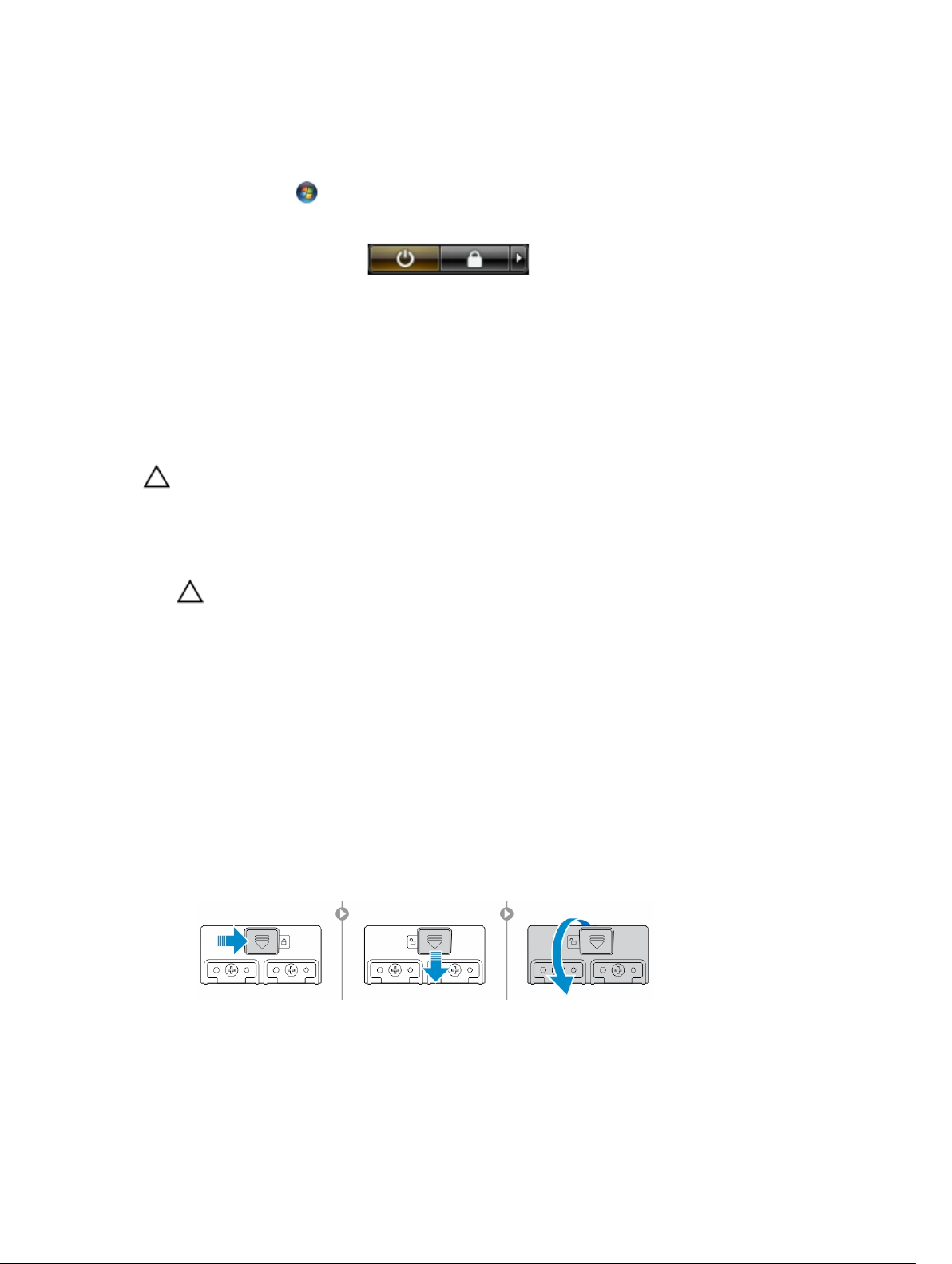
Opening the Press-Latch Doors
There are six press-latch doors. Three on the back and two on the right side panel. An extra press-latch
door is also present on the left side of the computer.
To open the press-latch doors:
a. Left and right side press-latch doors: Slide the latch towards the back of the computer to lock
and towards the front to unlock.
b. Back press-latch door: Slide the latch to the right to lock and to the left to unlock.
c. Press down the latch and pull the door in the direction away from the computer.
7
Removing and Installing Components
This section provides detailed information on how to remove or install the components from your
computer.
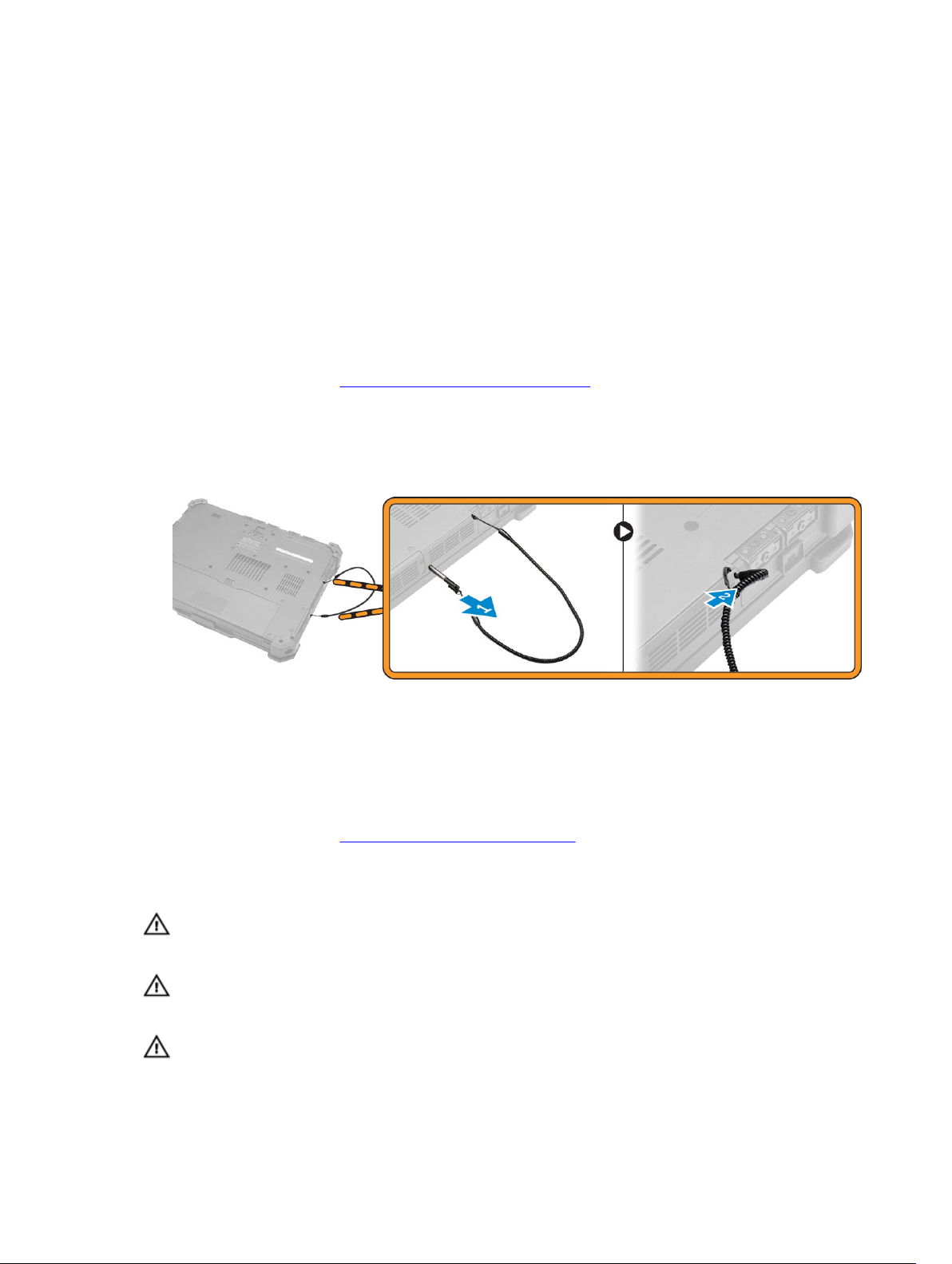
Removing the Stylus and Tether
1. Follow the procedures in Before Working Inside Your Computer
2. To remove stylus and tether:
a. Pull the stylus out from it’s slot on the computer [1].
b. Release and remove the tether from the computer [2].
2
Installing the Stylus and Tether
1. Insert the tether into the slot on the computer
2. Insert the stylus into its slot and push it inwards.
3. Follow the procedures in After Working Inside Your computer.
Removing the Battery
WARNING: Using an incompatible battery may increase the risk of fire or explosion. Replace the
battery only with a compatible battery purchased from Dell. The battery is designed to work with
your Dell computer. Do not use a battery from other computers with your computer.
WARNING: Using an incompatible battery may increase the risk of fire or explosion. Replace the
battery only with a compatible battery purchased from Dell. The battery is designed to work with
your Dell computer. Do not use a battery from other computers with your computer.
WARNING: Not for use in hazardous locations. See installation instructions.
8
WARNING: To prevent ignition in a hazardous atmosphere, batteries must only be changed or
charged in an area known to be non-hazardous.
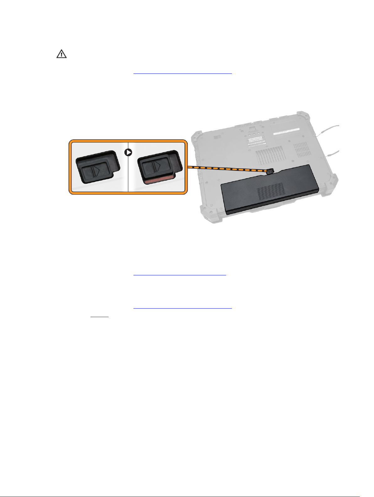
1. Follow the procedures in Before Working Inside Your Computer.
2. To remove the battery:
a. Push the battery latch towards the back of the computer.
b. Slide the latch to release the battery.
c. Slide the battery out of the computer.
Installing the Battery
1. Slide the battery into the battery bay.
2. Slide the latch to lock position.
3. Follow the procedures in After Working Inside Your computer.
Removing the Bottom Cover
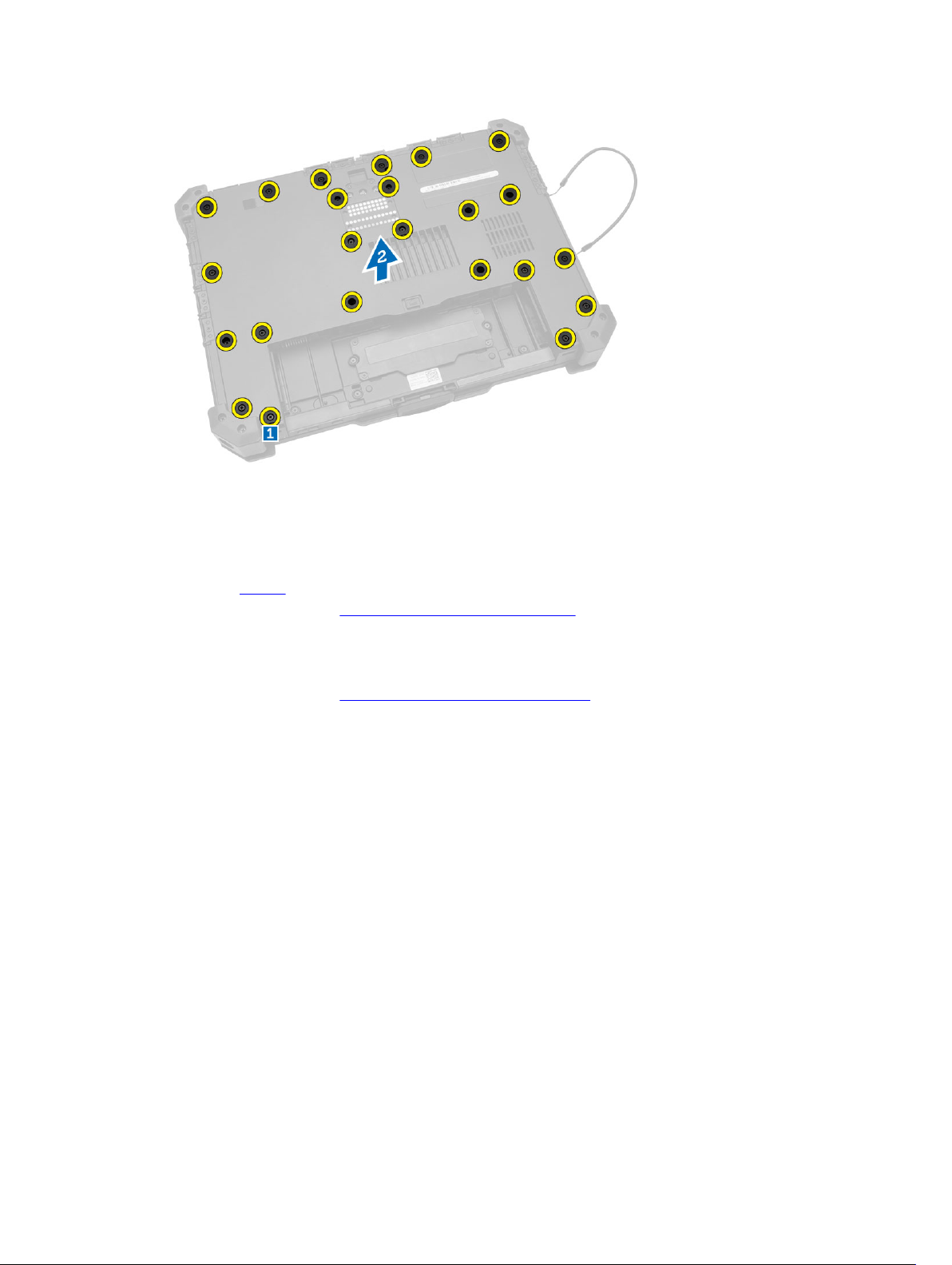
1. Follow the procedures in Before Working Inside Your Computer.
2. Remove battery.
3. To remove the bottom cover:
a. Remove the screws that secure the bottom cover [1].
b. Lift the bottom cover to remove it from the computer chassis [2].
9
Installing the Bottom Cover
1. Place the bottom cover on the base of the computer.
2. Tighten the screws that secure the bottom cover to the computer chassis.
3. Install the battery.
4. Follow the procedures in After Working Inside Your computer.
Removing the Keyboard and Keyboard door
1. Follow the procedures in Before Working Inside Your Computer.
2. To release the keyboard:
a. Remove the screws that secure the keyboard to the computer chassis [1].
b. Pry along the edges and flip the keyboard over [2].
10
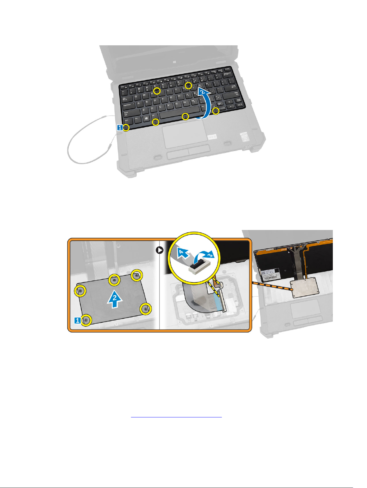
3. To remove the keyboard door:
a. Remove the screws that secure the keyboard door [1].
b. Lift the keyboard door [2].
c. Disconnect the keyboard cables from the motherboard connector by pressing on the locking tab
and lifting the connector upwards [3,4].
d. Lift and remove the keyboard from the computer chassis.
Installing the Keyboard and Keyboard Door
1. Connect the keyboard cables to its connectors on the keyboard controller card.
2. Place the keyboard door over its slot on the computer chassis.
3. Tighten the screws that secure the keyboard door to the computer chassis.
4. Align the keyboard into its slot on the computer.
5. Tighten the screws to secure the keyboard to the computer.
6. Follow the procedures in After Working Inside Your computer.
11
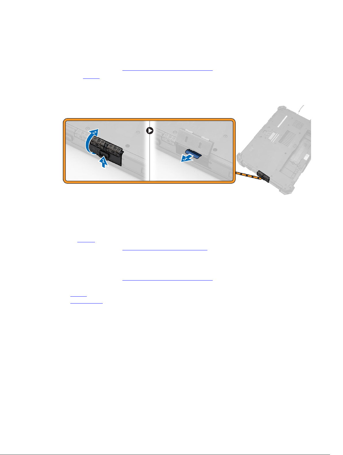
Removing the Hard Drive
1. Follow the procedures in Before Working Inside Your Computer.
2. Remove battery
3. To remove the hard drive:
a. Unlock the hard-drive press latch door and lift it upwards to open it [1,2].
b. Pull the tab to pull the hard drive out of the computer [3].
Installing the Hard Drive
1. Slide the hard drive into its place on the computer.
2. Close the hard-drive bay press latch door.
3. Install battery.
4. Follow the procedures in After Working Inside Your computer.
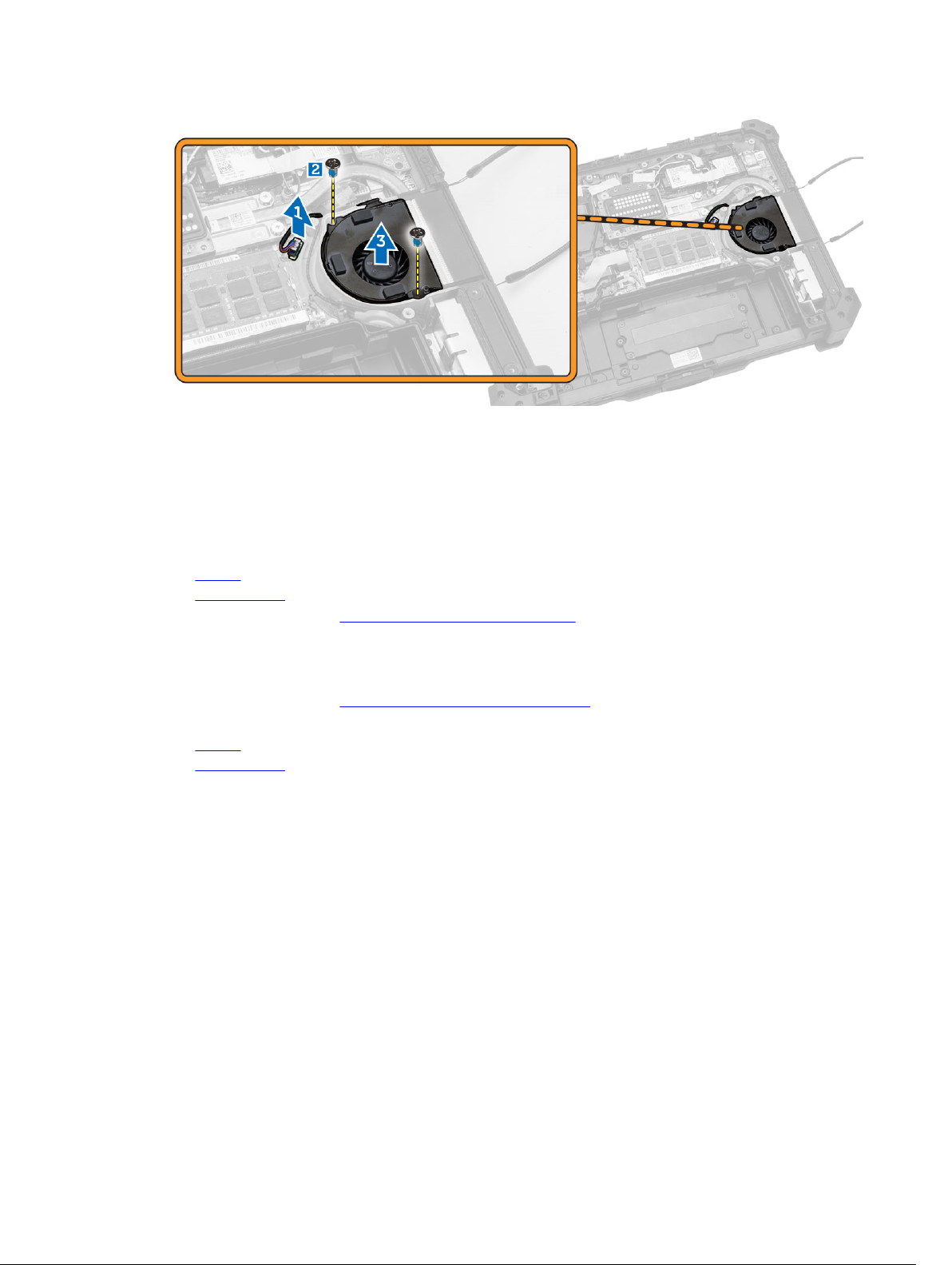
Removing the System Fan
1. Follow the procedures in Before Working Inside Your Computer.
2. Remove:
a. battery
b. bottom cover
3. To remove the system fan:
a. Disconnect the system fan cable from the system board [1].
b. Remove the screws that secure the system fan to the computer chassis [2].
c. Lift and remove the system fan from the computer chassis [3].
12
Installing the System Fan
1. Align the system fan in its position on the computer chassis.
2. Tighten the screws to secure the system fan to the computer chassis.
3. Connect the system fan connector cable to the system board connector.
4. Install:
a. battery
b. bottom cover
5. Follow the procedures in After Working Inside Your computer.
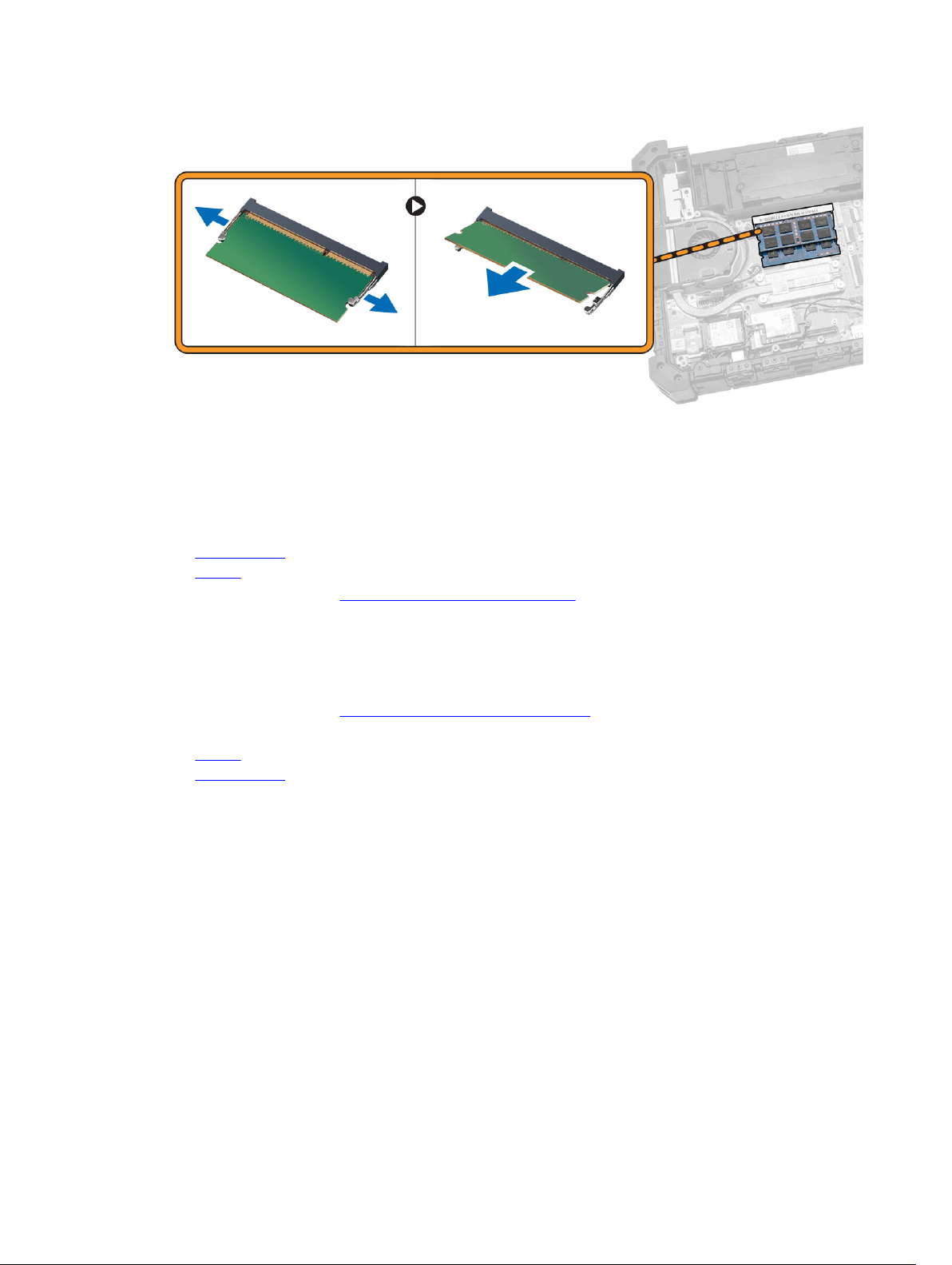
Removing the Memory Module
1. Follow the procedures in Before Working Inside Your Computer.
2. Remove:
a. battery
b. bottom cover
3. To remove the memory module:
a. Pry the securing clips away from the memory module until it pops up.
b. Remove the memory module from its connector on the system board.
13
Installing the Memory Module
1. Insert the memory module into the memory socket.
2. Press the memory module down until it clicks into place.
3. Install:
a. bottom cover
b. battery
4. Follow the procedures in After Working Inside Your computer.
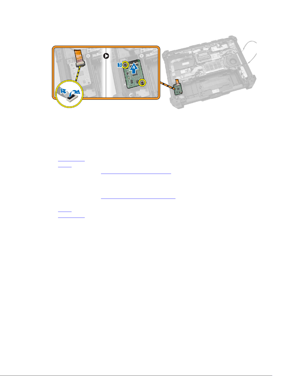
Removing the MEMS Board
MEMS board is also known as the sensor board.
1. Follow the procedures in Before Working Inside Your Computer.
2. Remove:
a. battery
b. bottom cover
3. To remove the MEMS board:
a. Disconnect the cable connected to the MEMS board [1,2].
b. Remove the screws that secure the MEMS board to the computer chassis [3].
c. Lift the MEMS board from the computer chassis [4].
14
Installing the MEMS Board
1. Place the MEMS board in the slot.
2. Tighten the screws to secure the MEMS board.
3. Connect the cable to the MEMS board.
4. Install:
a. bottom cover
b. battery
5. Follow the procedures in After Working Inside Your computer.
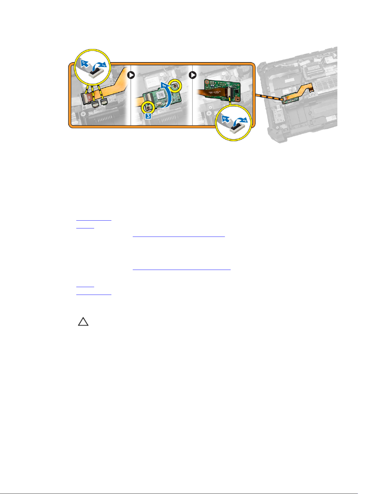
Removing the USH Board
1. Follow the procedures in Before Working Inside Your Computer.
2. Remove:
a. battery
b. bottom cover
3. To remove the USH board:
a. Disconnect the USH board cables from the connectors [1,2].
b. Remove the screws that secure the board [3].
c. Lift and flip the board at an angle to access the smart card cable at the bottom [4].
d. Disconnect the smart card cable and release the USH board from the computer chassis [5,6].
e. Remove the USH board from the computer.
15
Installing the USH Board
1. Connect the smart card cable to the USH board at the bottom of the board.
2. Flip the USH board to replace it to its original position.
3. Tighten the screws to secure the USH board.
4. Connect the cables to the USH board.
5. Install:
a. bottom cover
b. battery
6. Follow the procedures in After Working Inside Your computer.
Removing the Docking Board
1. Follow the procedures in Before Working Inside Your Computer.
2. Remove:
a. battery
b. bottom cover
3. To release the docking board:
a. Disconnect the antenna cables from the docking board [1].
CAUTION: Exercise caution while disconnecting the antenna cables. Improper removal
may result in damage/breakage of the antenna cables.
b. Remove the screws that secure the docking board [2].
16
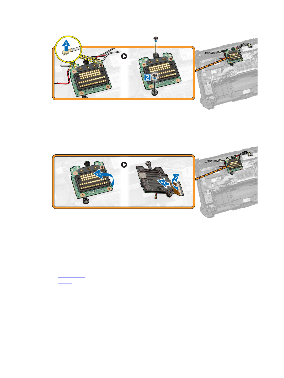
4. To remove the docking board:
a. Flip the board [1].
b. Disconnect the docking board connector cable from the system board by lifting the cable-
release tab [2].
c. Lift and remove the docking board from the computer chassis [3].
Installing the Docking Board
1. Connect the docking board connector cable to the system board.
2. Flip the docking board and seat it on the slot.
3. Tighten the screws to secure the docking board.
4. Connect the antenna cables to the docking board.
5. Install:
a. bottom cover
b. battery
6. Follow the procedures in After Working Inside Your Computer.
Removing the Heatsink
1. Follow the procedures in Before Working Inside Your Computer.
2. Remove:
17
a. battery
b. bottom cover
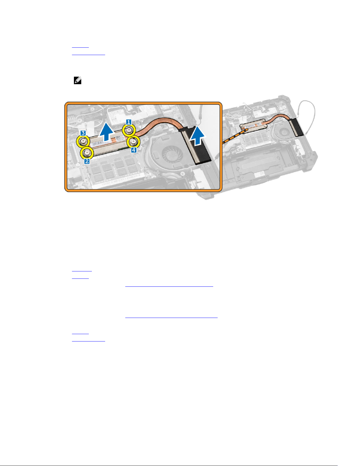
3. To remove heatsink:
a. Loosen the screws that secure the heatsink to the system board in the sequence shown [1,2,3,4].
NOTE: The screws are retained by the heatsink and should not be fully removed.
b. Lift and remove the heatsink from the computer chassis.
Installing the Heatsink
1. Clean the old thermal grease and re-apply the grease at the base of the heatsink.
2. Align the heatsink to its position on the system board.
3. Tighten the screws in the numerical sequence depicted on the bracket, to secure the heatsink on the
system board.
4. Install:
a. heatsink
b. battery
5. Follow the procedures in After Working Inside Your Computer.
Removing the Speaker
1. Follow the procedures in Before Working Inside Your Computer.
2. Remove:
a. battery
b. bottom cover
3. To remove the speaker:
a. Disconnect the speaker cable from the system board [1].
b. Remove the screws that secure the speaker module to the computer chassis [2].
c. Lift the speaker module and remove it from the computer chassis [3].
18
 Loading...