

Page 1
Products
Services
Support
Technical Support Dell Forums
Page
1
of 24Documentation
6.07.2007
http://support.euro.dell.com/support/edocs/systems/720H2C/en/OM/appendix.htm
You are here: Dell Em erging Markets – EMEA > Support Home Page
Back to Contents Page
Appendix
Dell™ XPS™ 720 Owner's Manual
Specifications
System Setup
Clearing Forgotten Passwords
Clearing CMOS Settings
Cleaning Your Computer
FCC Notices (U.S. Only)
Contacting Dell
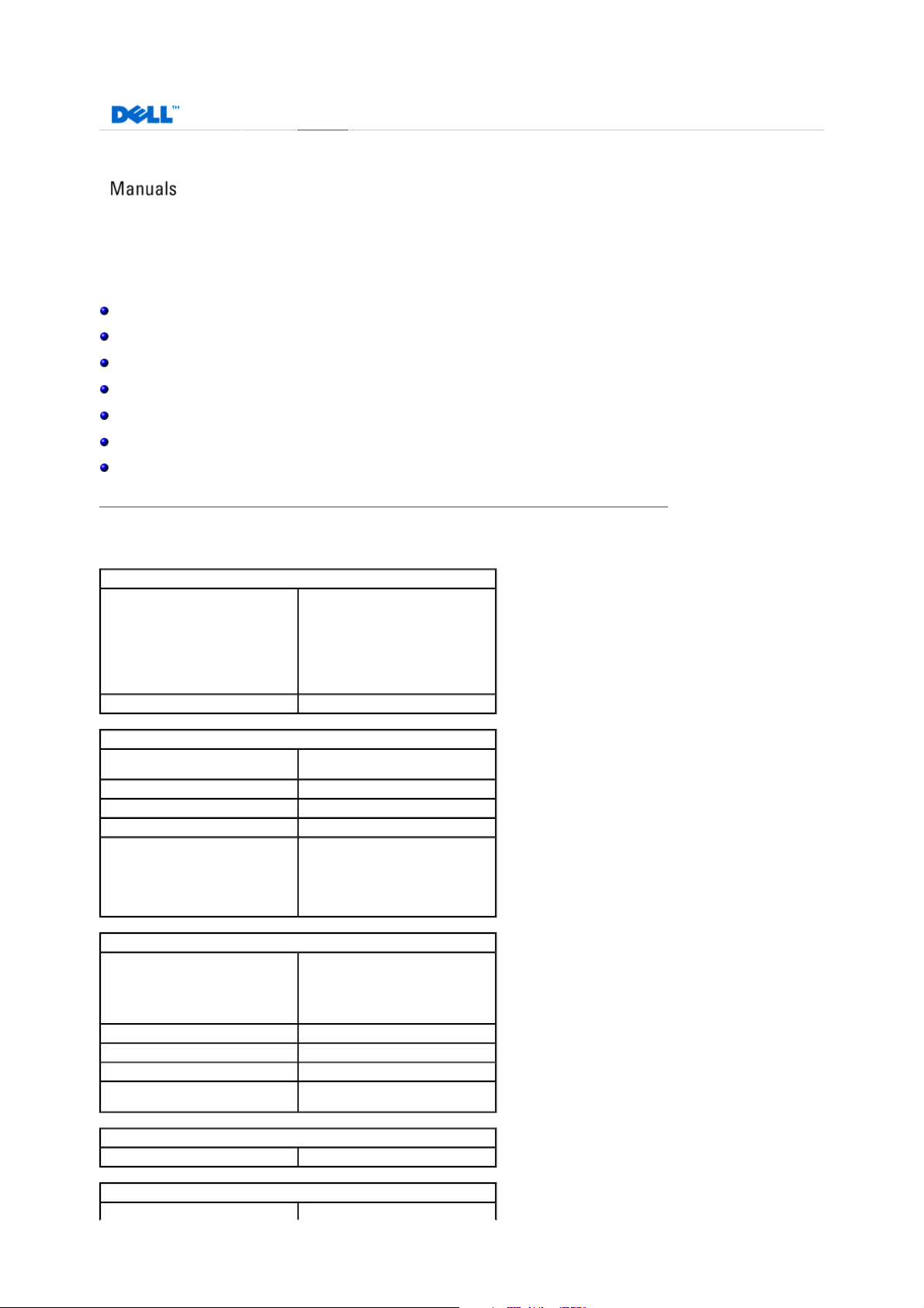
Specifications
About Dell|How to Buy
Processor
Processor type Intel® Core™ 2 Duo (dual-core
Cache at least 1 MB
Memory
Type 800, and 667-MHz DDR2 unbuffered
Memory connectors four
Memory capacities 512 MB, 1 GB, or 2 GB non-ECC
Minimum memory 1 GB
Maximum memory 8 GB
Computer Information
Chipset
Northbridge
Southbridge
DMA channels five
Interrupt levels 24
BIOS chip (NVRAM) 4 Mb
NIC integrated network interface capable of
processor)
Intel® Core™ 2 Extreme (dual-core
processor)
Intel® Core™ 2 Extreme (quad-core
processor)
SDRAM; SLI memory
NOTE: See Addressing Memory
Configurations to verify the amount of
memory available to the operating
system.
NVIDIA nForce 680i SLI
C55XE
MCP55PXE
10/100/1000 communication
Video
Type PCI Express
Audio
Page 2
Type HDA 7.1 channel
Page
2
of 24Documentation
6.07.2007
http://support.euro.dell.com/support/edocs/systems/720H2C/en/OM/appendix.htm
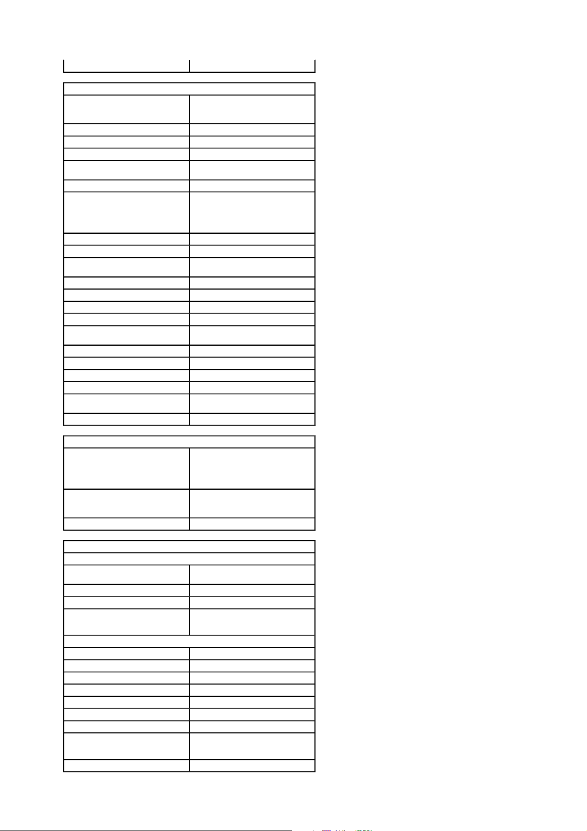
Expansion Bus
Bus type PCI Express x1 and x16
PCI 32-bit
PCI (SLOT3, SLOT5, SLOT6)
Connector three
Connector size 124 pins
Connector data width
(maximum)
Bus speed 33 MHz
PCI Express (SLOT1) NOTE: If a graphics card is installed in
Connector one x1
Connector size 36 pins
Connector data width
(maximum)
Bus throughput x1 slot bidirectional speed — 2.5 Gbps
PCI Express (SLOT7)
Connector one x16
Connector size 164 pins
Connector data width
(maximum)
Bus throughput x16 slot bidirectional speed — 20 Gbps
PCI Express (SLOT2, SLOT4)
Connector two x16
Connector size 164 pins
Connector data width
(maximum)
Bus throughput x16 slot bidirectional speed — 40 Gbps
32 bits
each of the PCI Express x16 card slots
in the dual-graphics configuration, the
PCI Express x1 card slot is not
accessible for use.
1 PCI Express lane
8 PCI Express lanes
16 PCI Express lanes
Drives
Available devices Serial ATA drive, floppy drive,
Externally accessible: two 3.5-inch drive bays
Internally accessible: four 3.5-inch drive bays for hard drives
Connectors
External connectors:
IEEE 1394 front and back-panel 6-pin serial
Network adapter RJ45 connector
PS/2 (keyboard and mouse) two 6-pin mini-DIN
USB two front-panel, six back-panel, and
System board connectors:
IDE drive one 40-pin connector
Serial ATA six 7-pin connectors
Floppy drive 34-pin connector
Fan three 5-pin connectors
Liquid cooling (optional) one 12-pin connector
PCI three 124-pin connectors
PCI Express x1 36-pin connector
PCI Express x16 (SLOT7); card
length up to 17.8 cm (7 inches
only)
PCI Express x16 three 164-pin connectors
memory devices, Blu-ray™ Disc
drive, DVD drive, DVD-RW drive,
CD-RW/DVD combo drive, and
media card reader
four 5.25-inch drive bays
connectors
two internal USB 2.0–compliant
connectors
164-pin connector
Page 3
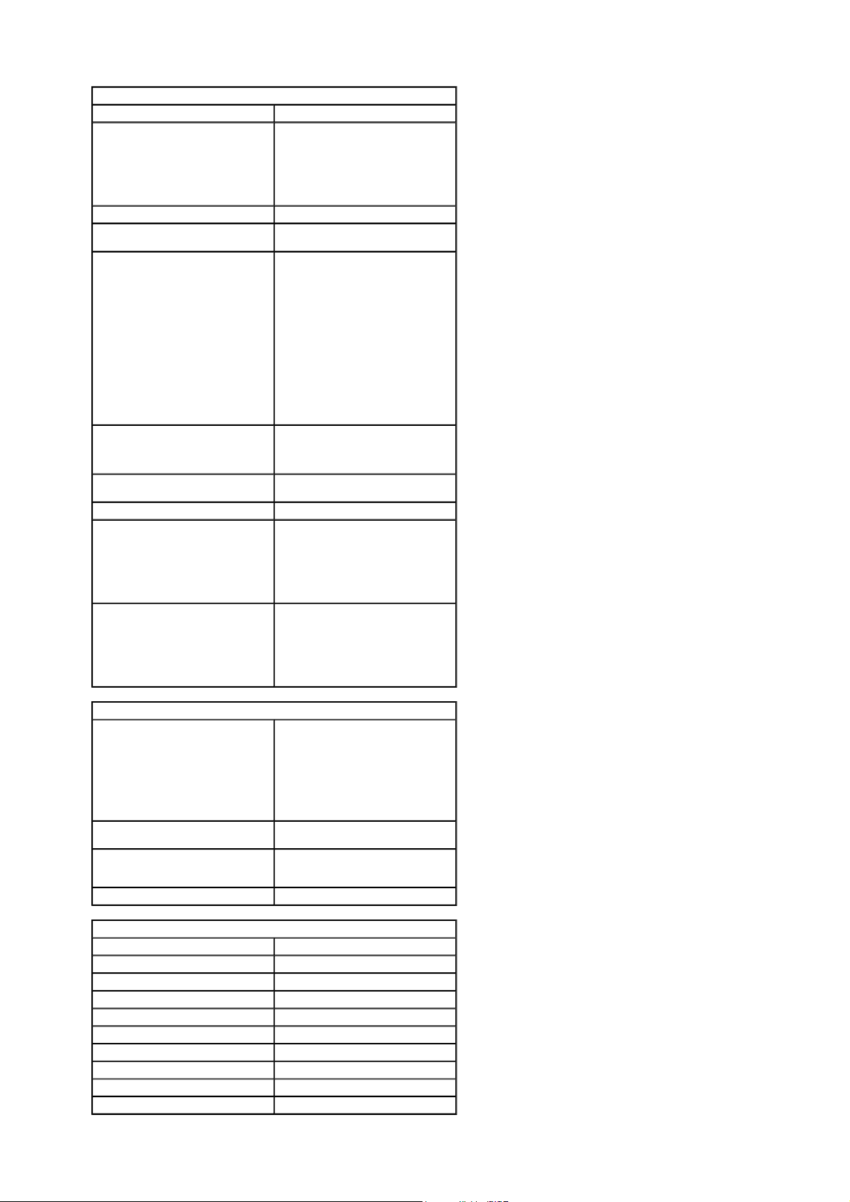
Controls and Lights
Page
3
of 24Documentation
6.07.2007
http://support.euro.dell.com/support/edocs/systems/720H2C/en/OM/appendix.htm
Power control push button
Power light green light — Blinking green in sleep
Hard-drive access light green
Network activity light (front panel) solid green indicates network
Link integrity light (on integrated
network adapter)
Activity light (on integrated network
adapter)
Diagnostic lights four lights on the front panel (see
Standby power light AUXPWR on the system board
Front panel LEDs eight multi-colored LEDs provide
Back panel LEDs two multi-colored lights provide
state; solid green for power-on state.
amber light — Blinking amber indicates
a problem with an installed device;
solid amber indicates an internal power
problem.
connection
green light — A good connection exists
between a 10-Mbps network and the
computer.
orange light — A good connection exists
between a 100-Mbps network and the
computer.
yellow light — A good connection exists
between a 1-GB (1000-Mbps) network
and the computer.
off (no light) — The computer is not
detecting a physical connection to the
network.
yellow blinking light when there is
activity on the network; if there is not
any network activity, the light will be
off
Diagnostic Lights)
illumination for the front of the
computer
NOTE: The color of the front panel
LEDs can be adjusted in system setup
(see System Setup).
illumination for the I/O panel on the
back of the computer
NOTE: The color of the back panel
LEDs can be adjusted in system setup
(see System Setup).
Power
DC power supply: CAUTION: To reduce the risk of fire,
Wattage 750 W or
Voltage (see the safety
instructions located in the
Product Information Guide)
Backup battery 3-V CR2032 lithium coin cell
Physical
Height
Without stand 55.5 cm (21.9 inches)
With stand 57.2 cm (22.5 inches)
Width
Without stand 21.9 cm (8.6 inches)
With stand 35.6 cm (14.0 inches)
Depth 59.4 cm (23.4 inches)
Weight
Typical configuration 21.7 kg (47.8 lb)
Maximum configuration 25.6 kg (56.4 lb)
electric shock, or injury, do not
overload an electrical outlet, power
strip, or convenience receptacle.
The total ampere rating of all
products plugged into an electrical
outlet, power strip, or other
receptacle should not exceed 80
percent of the branch circuit rating.
1 KW
auto-sensing power supply—90 V to
265 V at 50/60 Hz
Page 4
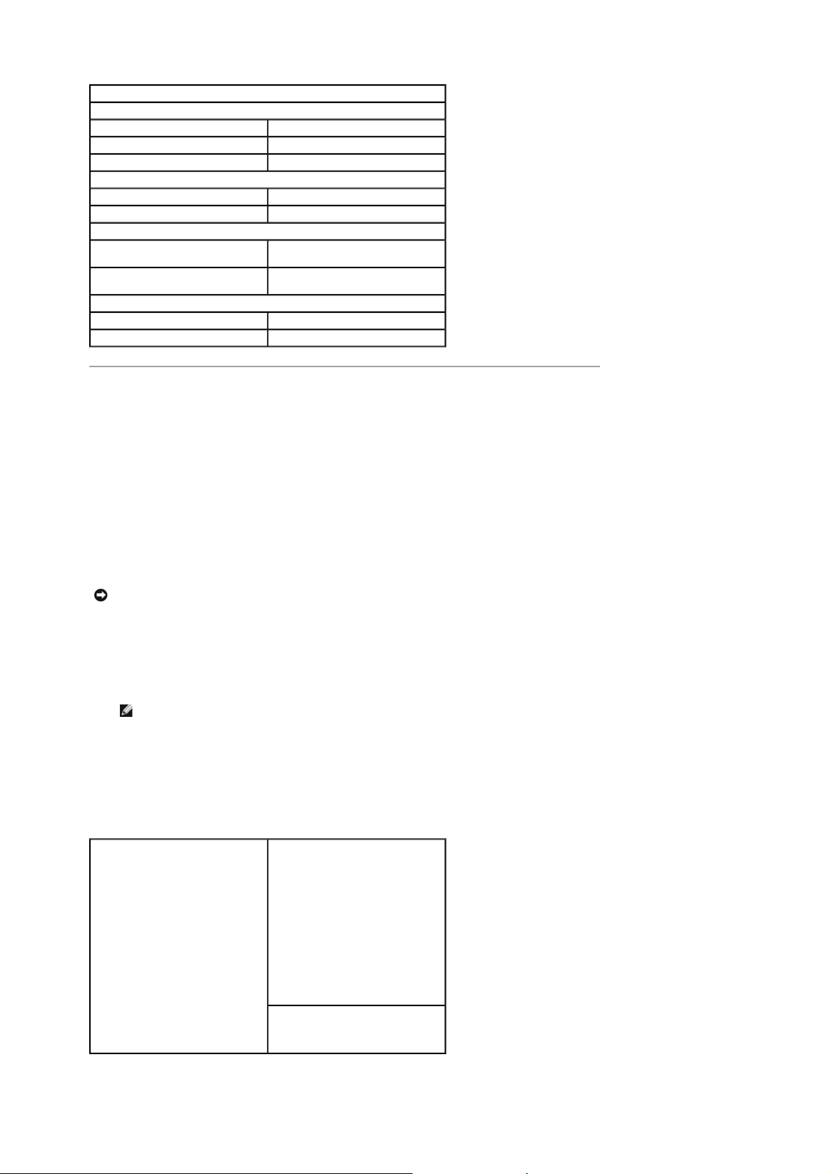
Environmental
Page
4
of 24Documentation
6.07.2007
http://support.euro.dell.com/support/edocs/systems/720H2C/en/OM/appendix.htm
Temperature:
Operating 10° to 35°C (50° to 95°F)
Storage –40° to 65°C (–40° to 149°F)
Relative humidity 20% to 80% (noncondensing)
Maximum vibration:
Operating 0.25 G at 3 to 200 Hz at 0.5 octave/min
Storage 0.5 G at 3 to 200 Hz at 1 octave/min
Maximum shock:
Operating bottom half-sine pulse with a change in
Storage 27-G faired square wave with a velocity
Altitude:
Operating –15.2 to 3048 m (–50 to 10,000 ft)
Storage –15.2 to 10,668 m (–50 to 35,000 ft)
velocity of 20 inches/sec (50.8 cm/sec)
change of 200 inches/sec (508 cm/sec)
System Setup
Overview
Use system setup as follows:
To change the system configuration information after you add, change, or remove any hardware in your
computer
To set or change a user-selectable option such as the user password
To read the current amount of memory or set the type of hard drive installed
Before you use system setup, it is recommended that you write down the system setup screen information for future
reference.
NOTICE: Do not change the settings in system setup unless you are an expert computer user. Certain changes
can cause your computer to work incorrectly.
Entering System Setup
1. Turn on (or restart) your computer.
2. When the DELL logo appears, press <F2> immediately.
NOTE: Keyboard failure may result when a key on the keyboard is held down for extended periods of time. To
avoid possible keyboard failure, press and release <F2> in even intervals until the system setup screen appears.
If you wait too long and the operating system logo appears, continue to wait until you see the Microsoft®
Windows® desktop, then shut down your computer and try again.
System Setup Screens
The system setup screen displays current or changeable configuration information for your computer. Information on
the screen is divided into three areas: the options list, the active options field, and key functions.
Options List — This field appears on
the left side of the system setup
window. The field is a scrollable list
containing features that define the
configuration of your computer,
including installed hardware, power
conservation, and security features.
Scroll up and down the list with the upand down-arrow keys. As an option is
highlighted, the Options Field displays
more information about that option and
the option's current and available
settings.
Options Field — This field appears on
the right side of the system setup
window and contains information about
each option listed in the Options List.
In this field you can view information
about your computer and make
changes to your current settings.
Press the left- and right-arrow keys to
highlight an option. Press <Enter> to
make that selection active and return to
the Options List.
NOTE: Not all settings listed in the
Options Field are changeable.
Key Functions — This field appears
below the Options Field and lists keys
and their functions within the active
system setup field.
System Setup Options
Page 5
NOTE: Depending on your computer and installed devices, the items listed in this section may not appear, or
Page
5
of 24Documentation
6.07.2007
http://support.euro.dell.com/support/edocs/systems/720H2C/en/OM/appendix.htm
may not appear exactly as listed.
System
System Info Lists system information, such as the
Processor Info Identifies the processor type, clock
Memory Info Identifies the memory type, speed, and
PCI Info Indicates the expansion card type by
Date/Time Displays current date and time settings.
Boot Sequence The computer attempts to boot from
computer name, the BIOS version
number and date, the system service
tag, express service code and asset tag,
and other system-specific information.
speed, bus speed, L2 cache, L3 cache,
ID, and whether the processor is
multiple core capable, supports HyperThreading and supports 64-bit
technology.
channel mode (dual or single) by DIMM
slot location.
slot location.
the sequence of devices specified in this
list.
NOTE: If you insert a boot device and
restart the computer, this option
appears in the system setup menu. To
boot from a USB memory device, for
example, select the USB device and
move it so that it becomes the first
device in the boot sequence.
Drives
Diskette Drive
(Internal default)
SATA Drives 0 through 5
(On default)
PATA Drives 0 through 1
(On default)
SMART Reporting
(Off default)
Enables and disables the floppy drive
attached to the DSKT connector on the
system board and sets read
permissions for the drive.
Off — All floppy drives are
disabled.
USB — USB floppy drives are
enabled
Internal — The integrated
floppy drive is enabled.
Read Only — The integrated
floppy drive is enabled with readonly access.
NOTE: Operating systems with USB
support will recognize USB floppy drives
regardless of this setting.
Enables or disables drives attached to
the SATA connectors on the system
board.
Off — A device attached to the
interface is not usable.
On — A device attached to the
interface is usable.
RAID On - A device attached to
the interface is configured for
RAID (see About Your RAID
Configuration).
Enables or disables drives attached to
the ATA connectors on the system
board, and lists the controller details.
Off — A device attached to the
interface is not usable.
On — A device attached to the
interface is usable.
Determines whether hard-drive errors
for internal drives are reported during
system startup.
Off — Errors are not reported.
On — Errors are reported.
Onboard Devices
Integrated NIC
(On default)
Enables or disables the integrated
network interface controller (NIC).
Off — The integrated NIC is
disabled.
Page 6
Integrated Audio
Page
6
of 24Documentation
6.07.2007
http://support.euro.dell.com/support/edocs/systems/720H2C/en/OM/appendix.htm
(On default)
USB Controller
(On default)
1394 Controller
(On default)
PS/2 Mouse Port
(On default)
On — The integrated NIC is
enabled.
On w/PXE — The integrated
NIC is on (with PXE enabled).
NOTE: PXE is required only if you are
booting to an operating system located
on another computer. If a boot routine
is not available from the remote
system, the computer attempts to boot
from the next device listed in the boot
sequence.
Enables or disables the onboard audio
controller.
Off — Integrated audio is
disabled.
On — Integrated audio is
enabled.
Enables or disables the internal USB
controller.
Off — The USB controller is
disabled.
On — The USB controller is
enabled.
No Boot — The USB controller is
enabled; however, the BIOS will
not recognize USB storage
devices.
NOTE: Operating systems with USB
support will recognize USB storage
devices regardless of the No Boot
setting.
Enables or disables the integrated IEEE
1394 controller.
Off — The 1394 controller is
disabled.
On — The 1394 controller is
enabled.
Enables or disables the onboard PS/2compatible mouse controller.
Off — The PS/2 legacy mouse
port is disabled.
On — The PS/2 legacy mouse
port is enabled.
LED Control
Front Upper LED
Front Lower LED
Rear Panel LED
LED Intensity
Performance
Multiple CPU Core
(On default)
Advanced Displays processor type and current
Adjusts the color of the upper front
panel LEDs (see Front and Back View of
the Computer).
Adjusts the color of the lower front
panel LEDs (see Front and Back View of
the Computer).
Adjusts the color of the rear panel LEDs
(see Front and Back View of the Computer).
Adjusts the intensity for the color of the
upper and lower front panel LEDs and
the rear panel LEDs.
Specifies whether the processor has
more than one core enabled.
Off — Multiple CPU core
technology is disabled.
On — Multiple CPU core
technology is enabled.
NOTE: The performance of some
applications may improve with an
additional core enabled.
BIOS settings for processor clock
speed, processor multiplier, front side
bus (FSB) clock, and CPU core voltage.
These settings may have been set by
performance tuning applications or may
change depending on settings in
performance applications that you have
installed.
Page 7
SpeedStep
Page
7
of 24Documentation
6.07.2007
http://support.euro.dell.com/support/edocs/systems/720H2C/en/OM/appendix.htm
(Off default)
Virtualization
(Off default)
HDD Acoustic Mode
(Bypass default)
For systems with Intel Extreme
processors, the following fields are
adjustable through the BIOS:
Processor Clock Speed: Adjusts
the multiplier of the processor.
For processors that cannot be
overclocked, this field reports the
current settings and cannot be
changed.
Performance Application
Support: Enables software
applications to display and
modify key system parameters to
tune system performance. These
applications are not installed or
supported by Dell. The default is
Off.
NOTE: To enable overclocking of other
system components, you first need to
enable the Performance Application
Support option in BIOS and then
download an application like NVIDIA
nTune version 5.0 or higher.
NOTE: Pressing <Alt><F> returns your
system to the factory defaults including
RAID settings.
Specifies whether Enhanced Intel
SpeedStep® technology is enabled for
all supported processors in the system.
Off — Disable Enhanced
SpeedStep technology
On — Enable Enhanced
SpeedStep technology
Specifies whether a virtual machine
monitor (VMM) can utilize the additional
hardware capabilities provided by Intel
Virtualization Technology
Off — Disable Virtualization
Technology
On — Enable Virtualization
Technology
Determines the acoustic mode at which
the hard drive operates.
Bypass — Do nothing (needed
for older drives).
Quiet — The hard drive operates
at a slower, but quieter speed.
Suggested — Allow the hard
drive manufacturer to select the
mode.
Performance — The hard drive
operates at a faster, but possibly
noisier speed.
NOTE: Switching to performance mode
may cause an increase in noise
produced by the drive, but does not
affect the drive's performance.
NOTE: Changing the acoustics setting
does not alter your hard drive image.
Security
Admin Password
(Not Set default)
System Password
(Not Set default)
Password Changes
(Unlocked default)
Execute Disable
(On default)
Used to prohibit an unauthorized user
from changing any configuration
settings in the system setup.
Used to prohibit an unauthorized user
from booting to the operating system.
This option locks the system password
field with the administrator (admin)
password.
NOTE: When the system password field
is locked, you can no longer disable
password security by pressing
<Ctrl><Enter> when the computer
starts.
Enables or disables Execute Disable
Memory Protection technology.
Off — Execute Disable Memory
Page 8
Protection technology is disabled.
Page
8
of 24Documentation
6.07.2007
http://support.euro.dell.com/support/edocs/systems/720H2C/en/OM/appendix.htm
On — Execute Disable Memory
Protection technology is enabled.
Power Management
AC Recovery
(Off default)
Auto Power On
(Off default)
Auto Power Time Specifies the time to automatically turn
Low Power Mode
(Off default)
Suspend Mode
(S3 default)
Specifies how the computer will behave
when AC power is restored after an AC
power loss.
Off — The system stays off after
AC power is restored.
On — The system powers on
after AC power is restored.
Last — The system returns to
the previous state after AC power
is restored.
Disables or selects when to
automatically turn on the computer.
Off — Do not use the Auto
Power Time.
Everyday — Turn the computer
on every day at the time set in
Auto Power Time.
Weekdays — Turn the computer
on Monday through Friday at the
time set in Auto Power Time.
NOTE: This feature does not work if
you turn off your computer using a
power strip or surge protector.
on the computer.
Change the time to automatically turn
on the computer by pressing the up- or
down-arrow key to increase or decrease
the numbers, or type the numbers in
the appropriate time field.
NOTE: This feature does not work if
you turn off your computer using a
power strip or surge protector.
Specifies how aggressive the system is
at conserving power while in hibernate
mode or turned off.
Off — Add more functionality.
On — Conserve more power.
Specifies the power management
suspend mode.
S1 — The computer resumes
more quickly from sleep mode.
S3 — The computer conserves
more power when not in use
(system memory remains
active).
Maintenance
Service Tag Displays the system service tag.
SERR Message
(On default)
Load Defaults This setting restores the computer's
Event Log Displays the system event log.
Controls the SERR message
mechanism. Some graphics cards
require that the SERR Message
mechanism be disabled.
Off — Do not use the SERR
message mechanism.
On — Use the SERR message
mechanism.
factory-installed default settings.
Cancel — Do not restore factoryinstalled default settings.
Continue — Restore factoryinstalled default settings.
Mark all entries — Mark all
event log entries as read (R).
Clear log — Clear all event log
entries.
NOTE: Once an event log entry is
marked as read (R) that entry cannot
Page 9

POST Behavior
Page
9
of 24Documentation
6.07.2007
http://support.euro.dell.com/support/edocs/systems/720H2C/en/OM/appendix.htm
Fastboot
(On default)
Numlock Key
(On default)
POST Hotkeys
(Setup & Boot Menu default)
Keyboard Errors
(Report default)
be marked as unread (U).
Enables or disables the option to speed
up the boot process by skipping some
compatibility tests.
Off — Do not skip any steps in
the boot process.
On — Boot quickly.
Enables or disables the numerical and
mathematical features of the rightmost
bank of keys on the keyboard.
Off — Right keypad keys
function as arrows.
On — Right keypad keys function
as numbers.
Specifies the function keys to display on
the screen when the computer starts.
Setup & Boot Menu — Display
both messages (F2=Setup and
F12=Boot Menu).
Setup — Display the setup
message only (F2=Setup).
Boot Menu — Display the
Quickboot message only
(F12=Boot Menu).
None — Neither message is
displayed.
Enables or disables keyboard error
reporting when the computer starts.
Report — Display any keyboard
errors.
Do not report — Do not display
any keyboard errors.
Boot Sequence
This feature allows you to change the boot sequence for the bootable devices installed o n your computer.
Option Settings
Diskette Drive — The computer attempts to boot from the floppy drive. If the floppy disk in the drive is not
bootable, if no floppy disk is in the drive, or if there is no floppy drive installed in the computer, the computer
attempts to boot from the next bootable device in the boot sequence.
Hard Drive — The computer attempts to boot from the primary hard drive. If no operating system is on the
drive, the computer attempts to boot from the next bootable device in the boot sequence.
CD Drive — The computer attempts to boot from the CD drive. If no CD is in the drive, or if the CD has no
operating system, the computer attempts to boot from the next bootable device in the boot sequence.
USB Flash Device — Insert the memory device into a USB port and restart the computer. When F12 = Boot
Menu appears in the upper-right corner of the screen, press <F12>. The BIOS detects the device and adds the
USB flash option to the boot menu.
NOTE: To boot to a USB device, the device must be bootable. To make sure that your device is bootable, check
the device documentation.
NOTE: An error message is generated only after the computer attempts to boot from every device in the boot
sequence and no operating system is found.
Changing Boot Sequence for the Current Boot
You can use this feature, for example, to tell the computer to boot from the CD drive so that you can run the Dell
Diagnostics on the Drivers and Utilities med ia, but you want the computer to boot from the hard drive when the
diagnostic tests are complete. You can also use this feature to restart your computer to a USB device such as a floppy
drive, memory key, or CD-RW drive.
NOTE: If you are booting to a USB floppy drive, you must first set the floppy drive to OFF in system setup (see
System Setup).
1. If you are booting to a USB device, connect the USB device to a USB connector (see Back View).
2. Turn on (or restart) your computer.
3. When the DELL logo appears, press <F12> immediately.
NOTE: Keyboard failure may result when a key on the keyboard is held down for extended periods of time. To
avoid possible keyboard failure, press and release <F12> in even intervals until the Boot Device Menu appears.
If you wait too long and the operating system logo appears, continue to wait until you see the Microsoft Windows
Page 10

desktop, then shut down your computer and try again.
Page
10
of 24Documentation
6.07.2007
http://support.euro.dell.com/support/edocs/systems/720H2C/en/OM/appendix.htm
4. At the Boot Device Menu, use the up- and down-arrow keys or press the appropriate number on the keyboard
to highlight the device that is to be used for the current boot only, and then press <Enter>.
For example, if you are booting to a USB memory key, highlight USB Flash Device and press <Enter>.
NOTE: To boot to a USB device, the device must be bootable. To make sure that your device is bootable, check
the device documentation.
Changing Boot Sequence for Future Boots
1. Enter system setup (see Entering System Setup ).
2. Use the arrow keys to highlight the Boot Sequence menu option and press <Enter> to access the menu.
NOTE: Write down your current boot sequence in case you want to restore it.
3. Press the up- and down-arrow keys to move through the list of devices.
4. Press the spacebar to enable or disable a device (enabled devices have a checkmark).
5. Press plus (+) or minus (–) to move a selected device up or down the list.
Clearing Forgotten Passwords
CAUTION: Before you begin any of the procedures in this section, follow the safety instructions in the
Product Information Guide.
NOTICE: This process erases both the system and setup passwords
1. Follow the procedures in Before You Begin .
2. Remove the computer cover (see Removing the Computer Cover).
3. Locate the 2-pin password jumper (PASSWORD) on the system board (see System Board Components), then
remove the jumper plug and set the plug aside.
4. Close the computer cover.
5. Connect your keyboard and mouse, then connect your computer and monitor to electr ical outlets and turn them
on.
6. After the Microsoft® Windows® desktop appears on your computer, turn the computer off:
a. Save and close all open files and exit all open programs.
b. Shut down the operating system:
In Windows XP, click Start→→→→ Turn Off Computer→→→→ Turn off.
In Windows Vista, click Start , click the arrow in the lower-right corner of the Start menu as
shown below, and then click Shut Down .
The computer turns off after the operating system shutdown process is complete.
NOTE: Ensure that the computer is off and not in a power management mode. If you cannot shut down the
computer using the operating system, press and hold the power button for 4 seconds.
7. Disconnect the keyboard and mouse, then disc onnect the computer and monitor from their electrical outlets.
8. Press the power button on the computer to ground the system board.
9. Open the computer cover (see
Removing the Computer Cover).
Page 11

NOTICE: The password jumper plug must be reinstalled on the password jumper pins in order to enable the
Page
11
of 24Documentation
6.07.2007
http://support.euro.dell.com/support/edocs/systems/720H2C/en/OM/appendix.htm
password feature.
10. Locate the 2-pin password jumper on the system board (see System Board Components), and then reinstall the
jumper plug to enable the password feature.
11. Replace the computer cover (see Replacing the Computer Cover).
NOTICE: To connect a network cable, first plug the cable into the network wall jack and then plug it into the
computer.
12. Connect your computer and devices to electrical outlets, and then turn them on.
NOTE: In system setup (see Entering System Setup), both system and administrator passwo rd options appear as
Not Set. The password feature is enabled but a password is not assigned.
Clearing CMOS Settings
CAUTION: Before you begin any of the procedures in this section, follow the safety instructions in the
Product Information Guide.
NOTE: This procedure does not clear or reset system and setup passwords.
1. Follow the procedures in Before You Begin .
2. Remove the computer cover (see Removing the Computer Cover).
3. Locate the password (PASSWORD) and CMOS (RTCRST) jumpers on the system board (see System Board
Components).
4. Remove the password jumper plug, then place the plug on the CMOS jumper pins and wait approximately 5
seconds.
NOTICE: The password jumper plug must be reinstalled on the password jumper pins in order to enable the
password feature.
5. Remove the jumper plug from the CMOS jumper pins, and then reinstall the plug on the password jumper pins to
enable the password feature.
6. Close the computer cover (see Replacing the Computer Cover).
NOTICE: To connect a network cable, first plug the cable into the network wall jack and then plug it into the
computer.
7. Connect your computer and devices to electrical outlets, and then turn them on.
Cleaning Your Computer
CAUTION: Before you begin any of the procedures in this section, follow the safety instructions in the
Product Information Guide.
Computer, Keyboard, and Monitor
CAUTION: Before you clean your computer, disconnect the computer fro m the electrical outlet. Clean
your computer with a soft cloth dampened with water. Do not use liquid or aerosol cleaners, which
may contain flammable substances.
Use a vacuum cleaner with a brush attachment to gently remove dust from the slots and holes on your computer
and from between the keys on the keyboard.
NOTICE: Do not wipe the display screen with any soap or alcohol solution. Doing so may damage the antiglare
coating.
To clean your monitor screen, lightly dampen a soft, clean cloth with water. If possible, use a special screencleaning tissue or solution suitable for the monitor's antistatic coating.
Wipe the keyboard, computer, and plastic part of the monitor with a soft cleaning cloth moistened with water.
Do not soak the cloth or let water drip inside your computer or keyboard.
Mouse
If your screen cursor skips or moves abnormally, clean the mouse. To clean a non-optical mouse:
1. Turn the retainer ring on the underside of your mouse counterclockwise, and then remove the ball.
2. Wipe the ball with a clean, lint-free cloth.
Page 12

Page
12
of 24Documentation
6.07.2007
http://support.euro.dell.com/support/edocs/systems/720H2C/en/OM/appendix.htm
3. Blow carefully into the ball cage to dislodge dust and lint.
4. If the rollers inside the ball cage are dirty, clean the rollers with a cotton swab moistened lightly with isopropyl
alcohol.
5. Recenter the rollers in their channels if they are misaligned. Ensure that fluff from the swab is not left on the
rollers.
6. Replace the ball and retainer ring, and turn the retainer ring clockwise until it clicks into place.
Floppy Drive
NOTICE: Do not attempt to clean drive heads with a swab. The heads may become misaligned and prevent the
drive from operating.
Clean your floppy drive using a commercially available cleaning kit. These kits contain pretreated floppy disks to
remove contaminants that accumulate during normal operation.
CDs and DVDs
NOTICE: Always use compressed air to clean the lens in the optical drive, and follow the instructions that come
with the compressed air. Never touch the lens in the drive.
If you notice problems, such as skipping, with the playback quality of your discs, try cleaning the discs.
1. Hold the disc by its outer edge. You can also touch the inside edge of the center hole.
NOTICE: To prevent damaging the surface, do not wipe in a circular motion around the disc.
2. With a soft, lint-free cloth, gently wipe the bottom of the disc (the unlabeled side) in a straight line from the
center to the outer edge of the disc.
For stubborn dirt, try using water or a diluted solution of water and mild soap. You can also purchase commercial
products that clean discs and provide some protection from dust, fingerprints, and scratches. Cleaning products
for CDs are safe to use on DVDs.
FCC Notices (U.S. Only)
Most Dell computer systems are classified by the Federal Communications Commission (FCC) as Class B digital devices.
To determine which classification applies to your computer system, examine all FCC registration labels located on the
bottom, side, or back panel of your computer, on card-mounting brackets, and on the cards themselves. If any one of
the labels carries a Class A rating, your entire system is considered to be a Class A digital device. If all labels carry an
FCC Class B rating as distinguished by either an FCC ID number or the FCC logo, ( ), your system is considered to
be a Class B digital device.
Once you have determined your system's FCC classification, read the appropriate FCC notice. Note that FCC regulations
provide that changes or modifications not expressly approved by Dell could void your autho rity to operate this
equipment.
This device complies with Part 15 of the FCC Rules. Operation is subject to the following two conditions:
1. This device may not cause harmful interference.
2. This device must accept any interference received, including interference that may cause undesired operation.
Class A
This equipment has been tested and found to comply with the limits for a Class A digital device pursuant to Part 15 of
the FCC Rules. These limits are designed to provide reasonable protection against harmful interference when the
equipment is operated in a commercial environment. This equipment generates, uses, and can radiate radio frequency
energy and, if not installed and used in accordance with the manufacturer's instruction manual, may cause harmful
interference with radio communications. Operation of this equipment in a residential area is likely to cause harmful
interference, in which case you will be required to correct the interference at your own expense.
Class B
This equipment has been tested and found to comply with the limits for a Class B digital device pursuant to Part 15 of
the FCC Rules. These limits are designed to provide reasonable protection against harmful interference in a residential
installation. This equipment generates, uses, and can radiate radio frequency energy and, if not installed and used in
accordance with the manufacturer's instruction manual, may cause interference with radio communications. However,
there is no guarantee that interference will not occur in a particular installation. If this equipment does cause harmful
interference to radio or television reception, which can be determined by turning the equipment off and on, you are
encouraged to try to correct the interference by one or more of the following measures:
Reorient or relocate the receiving antenna.
Increase the separation between the equipment and the receiver.
Connect the equipment into an outlet on a circuit different from that to which the receiver is connected.
Consult the dealer or an experienced radio/television technician for help.
Page 13

FCC Identification Information
Page
13
of 24Documentation
6.07.2007
http://support.euro.dell.com/support/edocs/systems/720H2C/en/OM/appendix.htm
The following information is provided on the device or devices covered in this document in compliance with FCC
regulations:
Product name: Dell™ XPS™ 720
Model number: DCDO
Company name:
Dell Inc.
One Dell Way
Round Rock, Texas 78682 USA
512-338-4400
Contacting Dell
You can contact Dell through the Internet and by phone:
For support through the web, go to support.dell.com.
For worldwide support through the web, use the Choose A Country/Region menu near the bottom of the
page, or see the web addresses listed in the following table.
For support by e-mail, see the e-mail addresses listed in the following table.
NOTE: Toll-free numbers are for use within the country for which they are listed.
NOTE: In certain countries, support specific to Dell™ XPS™ computers is available at a separate telephone
number listed for participating countries. If you do not see a telephone number listed that is specific for XPS
computers, you may contact Dell through the support number listed and your call will be routed appropriately.
For support by phone, use the phone numb ers and codes provided in the following table. If you need assistance
in determining which codes to use, contact a local or an international operator.
NOTE: The contact information provided was deemed correct at the time that this document went to print and is
subject to change.
Country (City)
International Access
Code Country Code
City Code
Anguilla
Antigua and Barbuda
Aomen
Country Code: 853
Argentina (Buenos
Aires)
International Access
Code: 00
Country Code: 54
City Code: 11
Aruba
Australia (Sydney)
Service Type
Web and E-mail Address
Online Support www.dell.com/ai
E-mail Address la-techsupport@dell.com
Technical Support, Customer Service,
Sales
Online Support
Technical Support, Customer Service,
Sales
Technical Support toll-free: 0800-105
Customer Service (Xiamen, China) 34 160 910
Transaction Sales (Xiamen, China) 29 693 115
Online Support www.dell.com.ar
E-mail for Desktops and Portables la-techsupport@dell.com
E-mail for Servers and EMC® Storage
Products
Customer Service toll-free: 0-800-444-0730
Technical Support – Dell PowerApp™, Dell
PowerEdge™, Dell PowerConnect™, and
Dell PowerVault™
Technical Support Services toll-free: 0-800-444-0724
Sales 0-810-444-3355
Online Support
Technical Support, Customer Service,
Sales
Online Support
toll-free: 800-335-0031
la-techsupport@dell.com
la_enterprise@dell.com
toll-free: 0-800-222-0154
la-techsupport@dell.com
support.ap.dell.com/contactus
Area Codes,
Local Numbers, and
Toll-Free Numbers
www.dell.com.ag
1-800-805-5924
www.dell.com.aw
toll-free: 800-1578
support.ap.dell.com
Page 14

International Access
Page
14
of 24Documentation
6.07.2007
http://support.euro.dell.com/support/edocs/systems/720H2C/en/OM/appendix.htm
Code: 0011
Country Code: 61
City Code: 2
Austria (Vienna)
International Access
Code: 900
Country Code: 43
City Code: 1
Bahamas
Barbados
Belgium (Brussels)
International Access
Code: 00
Country Code: 32
City Code: 2
Bermuda
Bolivia
Brazil
International Access
Code: 00
Country Code: 55
City Code: 51
British Virgin Islands
Brunei
Country Code: 673
Technical Support
Technical Support for XPS computers only toll-free: 1300 790 877
Home and Home Office toll-free: 1300-655-533
Medium and Large Business toll-free: 1800-633-559
Small Business, Education, Local
Government
Customer Service toll-free: 1300-662-196
Online Support
Technical Support for XPS computers only 08 20 24 05 30 81
Home/Small Business Sales 08 20 24 05 30 00
Home/Small Business Fax 08 20 24 05 30 49
Home/Small Business Customer Service 08 20 24 05 30 14
Home/Small Business Support 08 20 24 05 30 17
Preferred Accounts/Corporate Customer
Service
Preferred Accounts/Corporate Support 08 20 24 05 30 17
Switchboard 08 20 24 05 30 00
Online Support
Technical Support, Customer Service,
Sales
Online Support
Technical Support, Customer Service,
Sales
Online Support support.euro.dell.com
Technical Support for XPS computers only 02 481 92 96
General Support 02 481 92 88
General Support Fax 02 481 92 95
Customer Service 02 713 15 65
Corporate Sales 02 481 91 00
Fax 02 481 92 99
Switchboard 02 481 91 00
Online Support
Technical Support, Customer Service,
Sales
Online Support
Technical Support, Customer Service,
Sales
Online Support
Customer Service and Tech Support 0800 970 3355
Technical Support Fax 51 2104 5470
Customer Service Fax 51 2104 5480
Sales 0800 970 3390
Technical Support, Customer Service,
Sales
Technical Support (Penang, Malaysia) 604 633 4966
Customer Service (Penang, Malaysia)
Transaction Sales (Penang, Malaysia)
Online Order Status www.dell.ca/ostatus
Online Support support.ca.dell.com
AutoTech (automated Hardware and
tech_support_central_europe@dell.com
toll-free: 1800-060-889
support.euro.dell.com
08 20 24 05 30 16
www.dell.com/bs
la-techsupport@dell.com
toll-free: 1-866-874-3038
www.dell.com/bb
la-techsupport@dell.com
1-800-534-3142
www.dell.com/bm
la-techsupport@dell.com
1-877-890-0751
www.dell.com/bo
la-techsupport@dell.com
toll-free: 800-10-0238
www.dell.com/br
BR_TechSupport@dell.com
toll-free: 1-866-278-6820
604 633 3101
or toll-free: 801 1012
604 633 3101
or toll-free: 801 1012
toll-free: 1-800-247-9362
Page 15

Canada (North York,
Page
15
of 24Documentation
6.07.2007
http://support.euro.dell.com/support/edocs/systems/720H2C/en/OM/appendix.htm
Ontario)
International Access
Code: 011
Cayman Islands
Chile (Santiago)
Country Code: 56
City Code: 2
China (Xiamen)
Country Code: 86
City Code: 592
Colombia
Costa Rica
Warranty Support)
Customer Service
Home/Home Office toll-free: 1-800-847-4096
Small Business toll-free: 1-800-906-3355
Medium/Large Business, Government,
Education
Hardware Warranty Phone Support
XPS Computers Only toll-free: 1-866-398-8977
Computers for Home/Home Office toll-free: 1-800-847-4096
Computers for Small/Medium/Large
Business, Government
Printers, Projectors, Televisions,
Handheld, Digital Jukebox, and Wireless
Sales
Home and Home Office Sales toll-free: 1-800-999-3355
Small Business toll-free: 1-800-387-5752
Medium/Large Business, Government toll-free: 1-800-387-5755
Spare Parts and Extended Service 1 866 440 3355
Online Support la-techsupport@dell.com
Technical Support, Customer Service,
Sales
Online Support
Sales and Customer Support
Online Support support.dell.com.cn
Technical Support E-mail support.dell.com.cn/email
Customer Service E-mail customer_cn@dell.com
Technical Support Fax 592 818 1350
Technical Support – XPS computers only toll-free: 800 858 0540
Technical Support – Dell™ Dimension™
and Dell Inspiron™
Technical Support – Dell OptiPlex™, Dell
Latitude™, and Dell Precision™
Technical Support – Servers and Storage toll-free: 800 858 0960
Technical Support – Projectors, PDAs,
Switches, Routers, etc.
Technical Support – Printers toll-free: 800 858 2311
Customer Service toll-free: 800 858 2060
Customer Service Fax 592 818 1308
Home and Small Business toll-free: 800 858 2222
Preferred Accounts Division toll-free: 800 858 2557
Large Corporate Accounts GCP toll-free: 800 858 2055
Large Corporate Accounts Key Accounts toll-free: 800 858 2628
Large Corporate Accounts North toll-free: 800 858 2999
Large Corporate Accounts North
Government and Education
Large Corporate Accounts East toll-free: 800 858 2020
Large Corporate Accounts East
Government and Education
Large Corporate Accounts Queue Team toll-free: 800 858 2572
Large Corporate Accounts South toll-free: 800 858 2355
Large Corporate Accounts West toll-free: 800 858 2811
Large Corporate Accounts Spare Parts toll-free: 800 858 2621
Online Support
Technical Support, Customer Service,
Sales
Online Support
Technical Support, Customer Service,
toll-free: 1-800-387-5757
toll-free: 1-800-387-5757
1-877-335-5767
1-877-262-5415
www.dell.com/cl
la-techsupport@dell.com
toll-free: 1230-020-3397
or 800-20-1385
toll-free: 800 858 2969
toll-free: 800 858 0950
toll-free: 800 858 2920
toll-free: 800 858 2955
toll-free: 800 858 2669
www.dell.com/co
la-techsupport@dell.com
01-800-915-4755
www.dell.com/cr
la-techsupport@dell.com
Page 16

Czech Republic
Page
16
of 24Documentation
6.07.2007
http://support.euro.dell.com/support/edocs/systems/720H2C/en/OM/appendix.htm
(Prague)
International Access
Code: 00
Country Code: 420
Denmark
(Copenhagen)
International Access
Code: 00
Country Code: 45
Dominica
Dominican Republic
Ecuador
El Salvador
Finland (Helsinki)
International Access
Code: 990
Country Code: 358
City Code: 9
France (Paris)
(Montpellier)
International Access
Code: 00
Country Code: 33
City Codes: (1) (4)
Sales 0800-012-0231
Online Support
Technical Support 22537 2727
Customer Service 22537 2707
Fax 22537 2714
Technical Fax 22537 2728
Switchboard 22537 2711
Online Support support.euro.dell.com
Technical Support for XPS computers only 7010 0074
Technical Support 7023 0182
Customer Service – Relational 7023 0184
Home/Small Business Customer Service 3287 5505
Switchboard – Relational 3287 1200
Switchboard Fax – Relational 3287 1201
Switchboard – Home/Small Business 3287 5000
Switchboard Fax – Home/Small Business 3287 5001
Online Support
Technical Support, Customer Service,
Sales
Online Support
Technical Support, Customer Service,
Sales
Online Support
Technical Support, Customer Service,
Sales (calling from Quito)
Technical Support, Customer Service,
Sales (calling from Guayaquil)
Online Support
Technical Support, Customer Service,
Sales
Online Support
Technical Support 0207 533 555
Customer Service 0207 533 538
Switchboard 0207 533 533
Fax 0207 533 530
Sales under 500 employees 0207 533 540
Sales over 500 employees 0207 533 533
Online Support support.euro.dell.com
Technical Support for XPS computers only 0825 387 129
Home and Small Business
Technical Support 0825 387 270
Customer Service 0825 823 833
Switchboard 0825 004 700
Switchboard (calls from outside of
France)
Sales 0825 004 700
Fax 0825 004 701
Fax (calls from outside of France) 04 99 75 40 01
Corporate
Technical Support 0825 004 719
Customer Service 0825 338 339
Switchboard 01 55 94 71 00
toll-free: 1800-999-119-877-655-3355
support.euro.dell.com
czech_dell@dell.com
www.dell.com/dm
la-techsupport@dell.com
toll-free: 1-866-278-6821
www.dell.com/do
la-techsupport@dell.com
1-800-156-1588
www.dell.com/ec
la-techsupport@dell.com
toll-free: 999-119-877-655-3355
www.dell.com/sv
la-techsupport@dell.com
800-6132
support.euro.dell.com
fi_support@dell.com
04 99 75 40 00
Page 17

Germany (Frankfurt)
Page
17
of 24Documentation
6.07.2007
http://support.euro.dell.com/support/edocs/systems/720H2C/en/OM/appendix.htm
International Access
Code: 00
Country Code: 49
City Code: 69
Greece
International Access
Code: 00
Country Code: 30
Grenada
Guatemala
Guyana
Hong Kong
International Access
Code: 001
Country Code: 852
India
Sales 01 55 94 71 00
Fax 01 55 94 71 01
Online Support
Technical Support for XPS computers only 069 9792 7222
Technical Support 069 9792-7200
Home/Small Business Customer Service 0180-5-224400
Global Segment Customer Service 069 9792-7320
Preferred Accounts Customer Service 069 9792-7320
Large Accounts Customer Service 069 9792-7320
Public Accounts Customer Service 069 9792-7320
Switchboard 069 9792-7000
Online Support support.euro.dell.com
Technical Support 00800-44 14 95 18
Gold Service Technical Support 00800-44 14 00 83
Switchboard 2108129810
Gold Service Switchboard 2108129811
Sales 2108129800
Fax 2108129812
Online Support
Technical Support, Customer Service,
Sales
Online Support
Technical Support, Customer Service,
Sales
Online Support la-techsupport@dell.com
Technical Support, Customer Service,
Sales
Online Support
Technical Support – XPS computers only 00852-3416 6923
Technical Support – Dimension and
Inspiron
Technical Support – OptiPlex, Latitude,
and Dell Precision
Technical Support – Servers and Storage 00852-2969 3196
Technical Support – Projectors, PDAs,
Switches, Routers, etc.
Customer Service 00852 -3416 0910
Large Corporate Accounts 00852-3416 0907
Global Customer Programs 00852-3416 0908
Medium Business Division 00852-3416 0912
Home and Small Business Division 00852-2969 3105
Online Support support.ap.dell.com
Portable and Desktop Support
Desktop Support E-mail india_support_desktop@dell.com
Portable Support E-mail india_support_notebook@dell.com
Phone Numbers
Server Support
E-mail india_support_Server@dell.com
Phone Numbers
Gold Support Only
E-mail eec_ap@dell.com
Phone Numbers
tech_support_central_europe@dell.com
or your city STD code + 60003355
or your city STD code + 60003355
or your city STD code + 60003355
support.euro.dell.com
www.dell.com/gd
la-techsupport@dell.com
toll-free: 1-866-540-3355
www.dell.com/gt
la-techsupport@dell.com
1-800-999-0136
toll-free: 1-877-270-4609
support.ap.dell.com
support.dell.com.cn/email
00852-2969 3188
00852-2969 3191
00852-3416 0906
080-25068032 or 080-25068034
or toll-free: 1-800-425-8045
080-25068032 or 080-25068034
or toll-free: 1800 425 8045
080-25068033
or toll-free: 1-800-425-9045
Page 18

Ireland (Cherrywood)
Page
18
of 24Documentation
6.07.2007
http://support.euro.dell.com/support/edocs/systems/720H2C/en/OM/appendix.htm
International Access
Code: 00
Country Code: 353
City Code: 1
Italy (Milan)
International Access
Code: 00
Country Code: 39
City Code: 02
Jamaica
XPS Support Only
E-mail Indiaxps_AP@dell.com
Phone Numbers
Customer Service
Home and Small Business
Large Corporate Accounts
Sales
Large Corporate Accounts 1600 33 8044
Home and Small Business 1600 33 8046
Online Support
Technical Support
XPS computers only 1850 200 722
Business computers 1850 543 543
Home computers 1850 543 543
At Home Support 1850 200 889
Sales
Home 1850 333 200
Small Business 1850 664 656
Medium Business 1850 200 646
Large Business 1850 200 646
Sales E-mail Dell_IRL_Outlet@dell.com
Customer Service
Home and Small Business 01 204 4014
Business (greater than 200 employees) 1850 200 982
General
Fax/Sales Fax 01 204 0103
Switchboard 01 204 4444
U.K. Customer Service (dial within U.K.
only)
Corporate Customer Service (dial within
U.K. only)
U.K. Sales (dial within U.K. only) 0870 907 4000
Online Support support.euro.dell.com
Home and Small Business
Technical Support 02 577 826 90
Customer Service 02 696 821 14
Fax 02 696 821 13
Switchboard 02 696 821 12
Corporate
Technical Support 02 577 826 90
Customer Service 02 577 825 55
Fax 02 575 035 30
Switchboard 02 577 821
Online Support la-techsupport@dell.com
Technical Support, Customer Service,
Sales (dial from within Jamaica only)
Online Support support.jp.dell.com
Technical Support – XPS computers only toll-free: 0120-937-786
Technical Support outside of Japan – XPS
computers only
Technical Support – Dimension and
Inspiron
Technical Support outside of Japan –
Dimension and Inspiron
Technical Support – Dell Precision,
OptiPlex, and Latitude
or toll-free: 1-800-425-2066
India_care_HSB@dell.com
India_care_REL@dell.com
dell_direct_support@dell.com
080-25068066
toll-free: 1800-4254051
toll-free: 1800-4252067
support.euro.dell.com
0870 906 0010
0870 907 4499
1-800-440-9205
81-44-520-1235
toll-free: 0120-198-226
81-44-520-1435
toll-free: 0120-198-433
Page 19

Japan (Kawasaki)
Page
19
of 24Documentation
6.07.2007
http://support.euro.dell.com/support/edocs/systems/720H2C/en/OM/appendix.htm
International Access
Code: 001
Country Code: 81
City Code: 44
Korea (Seoul)
International Access
Code: 001
Country Code: 82
City Code: 2
Latin America
Luxembourg
International Access
Code: 00
Country Code: 352
Malaysia (Penang)
International Access
Code: 00
Country Code: 60
City Code: 4
Technical Support outside of Japan – Dell
Precision, OptiPlex, and Latitude
Technical Support – Dell PowerApp, Dell
PowerEdge, Dell PowerConnect, and Dell
PowerVault
Technical Support outside of Japan –
PowerApp, PowerEdge, PowerConnect,
and PowerVault
Technical Support – Projectors, PDAs,
Printers, Routers
Technical Support outside of Japan –
Projectors, PDAs, Printers, Routers
Faxbox Service 044-556-3490
24-Hour Automated Order Status Service 044-556-3801
Customer Service 044-556-4240
Business Sales Division – up to 400
employees
Preferred Accounts Division Sales – over
400 employees
Public Sales – government agencies,
educational institutions, and medical
institutions
Global Segment Japan 044-556-3469
Individual User 044-556-1657
Individual User Online Sales 044-556-2203
Individual User Real Site Sales 044-556-4649
Switchboard 044-556-4300
Online Support support.ap.dell.com
Technical Support for XPS computers only toll-free: 080-999-0283
Technical Support, Customer Service toll-free: 080-200-3800
Technical Support – Dimension, PDA,
Electronics, and Accessories
Sales toll-free: 080-200-3600
Fax 2194-6202
Switchboard 2194-6000
Customer Technical Support (Austin,
Texas, U.S.A.)
Customer Service (Austin, Texas, U.S.A.) 512 728-3619
Fax (Technical Support and Customer
Service) (Austin, Texas, U.S.A.)
Sales (Austin, Texas, U.S.A.) 512 728-4397
Sales Fax (Austin, Texas, U.S.A.)
Online Support support.euro.dell.com
Support 342 08 08 075
Home/Small Business Sales +32 (0)2 713 15 96
Corporate Sales 26 25 77 81
Customer Service +32 (0)2 481 91 19
Fax 26 25 77 82
Online Support support.ap.dell.com
Technical Support – XPS computers only toll-free: 1 800 885 784
Technical Support – Dell Precision,
OptiPlex, and Latitude
Technical Support – Dimension, Inspiron,
and Electronics and Accessories
Technical Support – PowerApp,
PowerEdge, PowerConnect, and
PowerVault
Customer Service toll-free: 1800 881 306 (option 6)
Transaction Sales toll-free: 1 800 888 202
Corporate Sales toll-free: 1 800 888 213
Online Support
Technical Support 001-866-563-4425
81-44-556-3894
toll-free: 0120-198-498
81-44-556-4162
toll-free: 0120-981-690
81-44-556-3468
044-556-1465
044-556-3433
044-556-5963
toll-free: 080-200-3801
512 728-4093
512 728-3883
512 728-4600
or 512 728-3772
toll-free: 1 800 880 193
toll-free: 1 800 881 306
toll-free: 1800 881 386
www.dell.com/mx
la-techsupport@dell.com
50-81-8800
Page 20

Mexico
Page
20
of 24Documentation
6.07.2007
http://support.euro.dell.com/support/edocs/systems/720H2C/en/OM/appendix.htm
International Access
Code: 00
Country Code: 52
Montserrat
Netherlands Antilles
Netherlands
(Amsterdam)
International Access
Code: 00
Country Code: 31
City Code: 20
New Zealand
International Access
Code: 00
Country Code: 64
Nicaragua
Norway (Lysaker)
International Access
Code: 00
Country Code: 47
Panama
Peru
Poland (Warsaw)
International Access
Code: 011
Country Code: 48
City Code: 22
Portugal
Sales
Customer Service
Main
Online Support la-techsupport@dell.com
Technical Support, Customer Service,
Sales
Online Support la-techsupport@dell.com
Technical Support, Customer Service,
Sales
Online Support support.euro.dell.com
Technical Support for XPS computers only 020 674 45 94
Technical Support 020 674 45 00
Technical Support Fax 020 674 47 66
Home/Small Business Customer Service 020 674 42 00
Relational Customer Service 020 674 4325
Home/Small Business Sales 020 674 55 00
Relational Sales 020 674 50 00
Home/Small Business Sales Fax 020 674 47 75
Relational Sales Fax 020 674 47 50
Switchboard 020 674 50 00
Switchboard Fax 020 674 47 50
Online Support
Technical Support for XPS computers only toll-free: 0800 335 540
Technical Support, Customer Service,
Sales
Online Support
Technical Support, Customer Service,
Sales
Online Support support.euro.dell.com
Technical Support for XPS computers only 815 35 043
Technical Support 671 16882
Relational Customer Service 671 17575
Home/Small Business Customer Service 23162298
Switchboard 671 16800
Fax Switchboard 671 16865
Online Support
Technical Support, Customer Service,
Sales
Online Support
Technical Support, Customer Service,
Sales
Online Support
Customer Service Phone 57 95 700
Customer Service 57 95 999
Sales 57 95 999
Customer Service Fax 57 95 806
Reception Desk Fax 57 95 998
Switchboard 57 95 999
Online Support support.euro.dell.com
Technical Support 707200149
or 001-800-888-3355
001-877-384-8979
or 001-877-269-3383
50-81-8800
or 001-800-888-3355
or 001-866-851-1754
toll-free: 1-866-278-6822
001-800-882-1519
support.ap.dell.com
support.ap.dell.com/contactus
0800 441 567
www.dell.com/ni
la-techsupport@dell.com
001-800-220-1377
www.dell.com/pa
la-techsupport@dell.com
011-800-507-1264
www.dell.com/pe
la-techsupport@dell.com
0800-50-669
support.euro.dell.com
pl_support_tech@dell.com
Page 21

International Access
Page
21
of 24Documentation
6.07.2007
http://support.euro.dell.com/support/edocs/systems/720H2C/en/OM/appendix.htm
Code: 00
Country Code: 351
Puerto Rico
St. Kitts and Nevis
St. Lucia
St. Vincent and the
Grenadines
Singapore (Singapore)
International Access
Code: 005
Country Code: 65
Slovakia (Prague)
International Access
Code: 00
Country Code: 421
South Africa
(Johannesburg)
International Access
Code:
09/091
Country Code: 27
City Code: 11
Southeast Asian and
Pacific Countries
Spain (Madrid)
International Access
Code: 00
Country Code: 34
Customer Service 800 300 413
Sales
Fax 21 424 01 12
Online Support
Technical Support
Customer Service and Sales 1-877-537-3355
Online Support
Technical Support, Customer Service,
Sales
Online Support
Technical Support, Customer Service,
Sales
Online Support
Technical Support, Customer Service,
Sales
NOTE: The phone numbers in this section
should be called from within Singapore or
Malaysia only.
Online Support support.ap.dell.com
Technical Support – XPS computers only toll-free: 1800 394 7464
Technical Support – Dimension, Inspiron,
and Electronics and Accessories
Technical Support – OptiPlex, Latitude,
and Dell Precision
Technical Support – PowerApp,
PowerEdge, PowerConnect, and
PowerVault
Customer Service toll-free: 1 800 394 7430 (option 6)
Transaction Sales toll-free: 1 800 394 7412
Corporate Sales toll-free: 1 800 394 7419
Online Support
Technical Support 02 5441 5727
Customer Service 420 22537 2707
Fax 02 5441 8328
Tech Fax 02 5441 8328
Switchboard (Sales) 02 5441 7585
Online Support
Gold Queue 011 709 7713
Technical Support 011 709 7710
Customer Service 011 709 7707
Sales 011 709 7700
Fax 011 706 0495
Switchboard 011 709 7700
Technical Support, Customer Service, and
Sales (Penang, Malaysia)
Online Support support.euro.dell.com
Home and Small Business
Technical Support 902 100 130
Customer Service 902 118 540
Sales 902 118 541
Switchboard 902 118 541
Fax 902 118 539
800 300 410 or 800 300 411 or 800 300 412
toll-free: 1-866-390-4695
toll-free: 1-866-540-3355
toll-free: 1-866-464-4352
toll-free: 1-866-464-4353
dell_za_support@dell.com
or 21 422 07 10
www.dell.com/pr
la-techsupport@dell.com
or 1-866-851-1760
www.dell.com/kn
la-techsupport@dell.com
www.dell.com/lc
la-techsupport@dell.com
www.dell.com/vc
la-techsupport@dell.com
toll-free: 1 800 394 7430
toll-free: 1 800 394 7488
toll-free: 1 800 394 7478
support.euro.dell.com
czech_dell@dell.com
support.euro.dell.com
604 633 4810
Page 22

City Code: 91 Corporate
Page
22
of 24Documentation
6.07.2007
http://support.euro.dell.com/support/edocs/systems/720H2C/en/OM/appendix.htm
Technical Support 902 100 130
Customer Service 902 115 236
Switchboard 91 722 92 00
Fax 91 722 95 83
Online Support support.euro.dell.com
Sweden (Upplands
Vasby)
International Access
Code: 00
Country Code: 46
City Code: 8
Switzerland (Geneva)
International Access
Code: 00
Country Code: 41
City Code: 22
Taiwan
International Access
Code: 002
Country Code: 886
Thailand
International Access
Code: 001
Country Code: 66
Trinidad/Tobago
Turks and Caicos
Islands
Technical Support for XPS computers only 77 134 03 40
Technical Support 08 590 05 199
Relational Customer Service 08 590 05 642
Home/Small Business Customer Service 08 587 70 527
Employee Purchase Program (EPP)
Support
Technical Support Fax 08 590 05 594
Sales 08 587 705 81
Online Support
Technical Support for XPS computers only 0848 338 857
Technical Support – Home and Small
Business
Technical Support – Corporate 0844 822 844
Customer Service – Home and Small
Business
Customer Service – Corporate 0848 821 721
Main 0848 335 599
Fax 022 799 01 90
Sales 022 799 01 01
Online Support
Technical Support – XPS computers only toll-free: 0080 186 3085
Technical Support – OptiPlex, Latitude,
Inspiron, Dimension, and Electronics and
Accessories
Technical Support – Servers and Storage toll-free: 0080 160 1256
Customer Service
Transaction Sales toll-free: 0080 165 1228
Corporate Sales toll-free: 0080 165 1227
Online Support support.ap.dell.com
Technical Support (OptiPlex, Latitude,
and Dell Precision)
Technical Support (PowerApp,
PowerEdge, PowerConnect, and
PowerVault)
Customer Service
Corporate Sales toll-free: 1800 006 009
Transaction Sales toll-free: 1800 006 006
Online Support
Technical Support, Customer Service,
Sales
Online Support
Technical Support, Customer Service,
Sales
Online Support
Customer Service Online support.euro.dell.com/uk/en/ECare/form/home.asp
Sales
Home and Small Business Sales 0870 907 4000
Corporate/Public Sector Sales 01344 860 456
Tech_support_central_Europe@dell.com
support.euro.dell.com
support.dell.com.cn/email
toll-free: 0080 186 1011
toll-free: 0080 160 1250
la-techsupport@dell.com
toll-free: 1-888-799-5908
la-techsupport@dell.com
toll-free: 1-877-441-4735
dell_direct_support@dell.com
020 140 14 44
0844 811 411
0848 802 202
support.ap.dell.com
(option 5)
toll-free: 1800 0060 07
toll-free: 1800 0600 09
toll-free: 1800 006 007
support.euro.dell.com
(option 7)
www.dell.com/tt
www.dell.com/tc
Page 23

U.K. (Bracknell)
Page
23
of 24Documentation
6.07.2007
http://support.euro.dell.com/support/edocs/systems/720H2C/en/OM/appendix.htm
International Access
Code: 00
Country Code: 44
City Code: 1344
Uruguay
U.S.A. (Austin, Texas)
International Access
Code: 011
Country Code: 1
U.S. Virgin Islands
Venezuela
Customer Service
Home and Small Business 0870 906 0010
Corporate 01344 373 185
Preferred Accounts (500–5000
employees)
Global Accounts 01344 373 186
Central Government 01344 373 193
Local Government & Education 01344 373 199
Health 01344 373 194
Technical Support
XPS Computers Only 0870 366 4180
Corporate/Preferred Accounts/PCA
(1000+ employees)
Other Dell Products 0870 353 0800
General
Home and Small Business Fax 0870 907 4006
Online Support
Technical Support, Customer Service,
Sales
Dell Services for the Deaf, Hard-ofHearing, or Speech-Impaired
Fax toll-free: 1-800 -727-8320
Technical Support support.dell.com
XPS toll-free: 1-800-232-8544
Home and Home Office toll-free: 1-800-624-9896
Portable and Desktop AutoTech toll-free: 1-800-247-9362
Small Business toll-free: 1-800-456-3355
Medium and Large Business toll-free: 1-877-671-3355
State and Local Government toll-free: 1-800-981-3355
Federal Government toll-free: 1-800-727-1100
Healthcare toll-free: 1-800-274-1550
K-12 Education toll-free: 1-888-977-3355
Higher Education toll-free: 1-800-274-7799
Printers, Projectors, PDAs, and MP3
Players
Customer Service toll-free: 1-800-624-9897
Automated Order Status toll-free: 1-800-433-9014
Small Business toll-free: 1-800-456-3355
Medium and Large Business toll-free: 1-877-671-3355
State and Local Government toll-free: 1-800-981-3355
Federal Government toll-free: 1-800-727-1100
Healthcare toll-free: 1-800-274-1550
K-12 Education toll-free: 1-888-977-3355
Higher Education toll-free: 1-800-274-7799
Employee Purchase Program (EPP) toll-free: 1-800-695-8133
Financial Services www.dellfinancialservices.com
Leases and Loans toll-free: 1-877-577-3355
Dell Preferred Accounts (DPA) toll-free: 1-800-283-2210
Sales 1-800-289-3355 or 1-800-879-3355
Dell Outlet Store toll-free: 1-888-798-7561
Software and Peripherals Sales toll-free: 1-800-671-3355
Online Support
Technical Support, Customer Service,
Sales
Online Support
Technical Support, Customer Service,
toll-free: 000-413-598-2521
toll-free: 1-877-459-7298
toll-free: 1-877-702-4360
0870 906 0010
0870 908 0500
www.dell.com/uy
la-techsupport@dell.com
toll-free: 1-877-DELLTTY
(1-877-335-5889)
www.dell.com/vi
la-techsupport@dell.com
www.dell.com/ve
la-techsupport@dell.com
Page 24

Sales 0800-100-4752
Page
24
of 24Documentation
6.07.2007
http://support.euro.dell.com/support/edocs/systems/720H2C/en/OM/appendix.htm
Back to Contents Page
You are here: Dell Em erging Markets – EMEA > Support Home Page
Large Text
sn WEB6
Terms and Conditi ons | Privacy Practice s | Contact a Res eller |
Copyright 1999-200 7 Dell Inc.
Top
 Loading...