

Page 1

Dell Inspiron 660
Owner’s Manual
Computer model: Inspiron 660
Regulatory model: D11M
Regulatory type: D11M002
Page 2

Notes, Cautions, and Warnings
NOTE: A NOTE indicates important information that helps you make better use of
your computer.
CAUTION: A CAUTION indicates potential damage to hardware or loss of data if
instructions are not followed.
WARNING: A WARNING indicates a potential for property damage, personal
injury, or death.
____________________
Information in this document is subject to change without notice.
© 2012 Dell Inc. All rights reserved.
Reproduction of these materials in any manner whatsoever without the written permission of Dell Inc.
is strictly forbidden.
Trademarks used in this text: Dell™, the DELL logo, and Inspiron™ are trademarks of Dell Inc.;
Microsoft
trademarks of Microsoft corporation in the United States and/or other countries; Bluetooth
registered trademark owned by Bluetooth SIG, Inc. and is used by Dell under license; Intel
Intel SpeedStep
Other trademarks and trade names may be used in this document to refer to either the entities claiming
the marks and names or their products. Dell Inc. disclaims any proprietary interest in trademarks and
trade names other than its own.
2012 - 04 Rev. A00
®
, Windows®, and the Windows start button logo are either trademarks or registered
®
are registered trademarks of Intel Corporation in the U.S. and/or other countries.
®
®
is a
and
Page 3

Contents
1 Before You Begin . . . . . . . . . . . . . . . . . . . 9
Turn Off Your Computer and Connected Devices . . . . . 9
Safety Instructions
Recommended Tools
. . . . . . . . . . . . . . . . . . . . 9
. . . . . . . . . . . . . . . . . . 10
2 After Working Inside Your Computer . . . 11
3 Technical Overview
Inside View of Your Computer . . . . . . . . . . . . . 13
System Board Components
. . . . . . . . . . . . . . . . . 13
. . . . . . . . . . . . . . . 14
4 Computer Cover . . . . . . . . . . . . . . . . . . . 17
Removing the Computer Cover . . . . . . . . . . . . . 18
Replacing the Computer Cover
. . . . . . . . . . . . . 19
5 Memory Module(s) . . . . . . . . . . . . . . . . . 21
Removing the Memory Module(s) . . . . . . . . . . . . 21
Replacing the Memory Module(s)
. . . . . . . . . . . 22
Contents 3
Page 4

6 Front Bezel . . . . . . . . . . . . . . . . . . . . . . . 25
Removing the Front Bezel . . . . . . . . . . . . . . . . 25
Replacing the Front Bezel
. . . . . . . . . . . . . . . . 27
7 Card Retention Bracket . . . . . . . . . . . . . . 29
Removing the Card Retention Bracket . . . . . . . . . 29
Replacing the Card Retention Bracket
. . . . . . . . . 31
8 PCI Express Cards . . . . . . . . . . . . . . . . . . 33
Removing PCI Express Cards . . . . . . . . . . . . . . 33
Replacing PCI Express Cards
Configuring Your Computer After Removing or
Installing the PCI Express Card
. . . . . . . . . . . . . . 35
. . . . . . . . . . . . . 37
9 Mini-Card . . . . . . . . . . . . . . . . . . . . . . . . . 39
Removing the Mini-Card . . . . . . . . . . . . . . . . . 40
Replacing the Mini-Card . . . . . . . . . . . . . . . . 41
10 Hard Drive(s) . . . . . . . . . . . . . . . . . . . . . . 43
4 Contents
Removing the Hard Drive(s) . . . . . . . . . . . . . . . 43
Replacing the Hard Drive(s)
. . . . . . . . . . . . . . . 48
Page 5

11 Optical Drive(s) . . . . . . . . . . . . . . . . . . . . 49
Removing the Optical Drive(s) . . . . . . . . . . . . . 49
Replacing the Optical Drives(s)
. . . . . . . . . . . . . 53
12 Front I/O Panel . . . . . . . . . . . . . . . . . . . . 57
Removing the Front I/O Panel . . . . . . . . . . . . . . 57
Replacing the Front I/O Panel
. . . . . . . . . . . . . . 59
13 Power Button Module . . . . . . . . . . . . . . . 61
Removing the Power Button Module . . . . . . . . . . 61
Replacing the Power Button Module
. . . . . . . . . . 63
14 Chassis Fan . . . . . . . . . . . . . . . . . . . . . . . 65
Removing the Chassis Fan . . . . . . . . . . . . . . . 65
Replacing the Chassis Fan
. . . . . . . . . . . . . . . 67
15 Processor Fan and
Heat-Sink Assembly
. . . . . . . . . . . . . . . . 69
Removing the Processor Fan and
Heat-Sink Assembly
Replacing the Processor Fan and
Heat-Sink Assembly
. . . . . . . . . . . . . . . . . . . 69
. . . . . . . . . . . . . . . . . . . 71
Contents 5
Page 6

16 Processor . . . . . . . . . . . . . . . . . . . . . . . . 73
Removing the Processor . . . . . . . . . . . . . . . . . 73
Replacing the Processor
. . . . . . . . . . . . . . . . 75
17 Coin-Cell Battery . . . . . . . . . . . . . . . . . . . 77
Removing the Coin-Cell Battery . . . . . . . . . . . . . 77
Replacing the Coin-Cell Battery
. . . . . . . . . . . . 79
18 Power Supply . . . . . . . . . . . . . . . . . . . . . 81
Removing the Power Supply . . . . . . . . . . . . . . 81
Replacing the Power Supply
. . . . . . . . . . . . . . 83
19 System Board . . . . . . . . . . . . . . . . . . . . . 85
Removing the System Board . . . . . . . . . . . . . . . 85
Replacing the System Board
Entering the Service Tag in the BIOS
. . . . . . . . . . . . . . 87
. . . . . . . . . . 88
20 System Setup . . . . . . . . . . . . . . . . . . . . . . 91
6 Contents
Overview . . . . . . . . . . . . . . . . . . . . . . . . . 91
Entering System Setup
Clearing Forgotten Passwords
Clearing CMOS Passwords
. . . . . . . . . . . . . . . . . . 91
. . . . . . . . . . . . . 102
. . . . . . . . . . . . . . . 104
Page 7

21 Flashing the BIOS . . . . . . . . . . . . . . . . . 107
22 Specifications . . . . . . . . . . . . . . . . . . . . 109
Contents 7
Page 8

8 Contents
Page 9
Before You Begin
Turn Off Your Computer and Connected Devices
CAUTION: To avoid losing data, save and close all open files and exit all open
programs before you turn off your computer.
1
Save and close all open files and exit all open programs.
2
Click
Start
and click
Microsoft Windows shuts down and then the computer turns off.
NOTE: If you are using a different operating system, see the documentation of
your operating system for shut-down instructions.
3
Disconnect your computer and all attached devices from their electrical outlets.
4
Disconnect all telephone cables, network cables, and attached devices from your computer.
5
Press and hold the power button, while the computer is unplugged, to ground the system board.
Safety Instructions
Use the following safety guidelines to protect your computer from potential
damage and ensure your personal safety.
Shut Down
.
WARNING: Before working inside your computer, read the safety information
that shipped with your computer. For additional safety best practices information,
see the Regulatory Compliance Homepage at dell.com/regulatory_compliance.
WARNING: Disconnect all power sources before opening the computer cover or
panels. After you finish working inside the computer, replace all covers, panels,
and screws before connecting to the power source.
CAUTION: To avoid damaging the computer, ensure that the work surface is flat
and clean.
CAUTION: To avoid damaging the components and cards, handle them by their
edges and avoid touching pins and contacts.
Before You Begin 9
Page 10

CAUTION: Only a certified service technician is authorized to remove the
computer cover and access any of the components inside the computer. See the
safety instructions for complete information about safety precautions, working
inside your computer, and protecting against electrostatic discharge.
CAUTION: Before touching anything inside your computer, ground yourself by
touching an unpainted metal surface, such as the metal at the back of the
computer. While you work, periodically touch an unpainted metal surface to
dissipate static electricity, which could harm internal components.
CAUTION: When you disconnect a cable, pull on its connector or on its pull-tab,
not on the cable itself. Some cables have connectors with locking tabs or
thumb-screws that you must disengage before disconnecting the cable. When
disconnecting cables, keep them evenly aligned to avoid bending any connector
pins. When connecting cables, ensure that the connectors and ports are correctly
oriented and aligned.
CAUTION: To disconnect a network cable, first unplug the cable from your
computer and then unplug the cable from the network device.
Recommended Tools
The procedures in this document may require the following tools:
• Small flat-blade screwdriver
• Small Phillips screwdriver
• Plastic scribe
• Flash BIOS executable update program available at
support.dell.com
10 Before You Begin
Page 11

After Working Inside Your Computer
After you complete replacement procedures, ensure the following:
• Replace all screws and ensure that no stray screws remain inside your
computer
• Connect any external devices, cables, cards, and any other part you
removed before working on your computer
• Connect your computer and all attached devices to their electrical outlets
CAUTION: Before turning on your computer, replace all screws and ensure that
no stray screws remain in the computer. Failure to do so may damage your
computer.
• Turn on your computer.
After Working Inside Your Computer 11
Page 12

12 After Working Inside Your Computer
Page 13
Technical Overview
1
6
4
3
9
10
8
2
7
5
WARNING: Before working inside your computer, read the safety information that
shipped with your computer and follow the steps in "Before You Begin" on page 9.
For additional safety best practices information, see the Regulatory Compliance
Homepage at dell.com/regulatory_compliance.
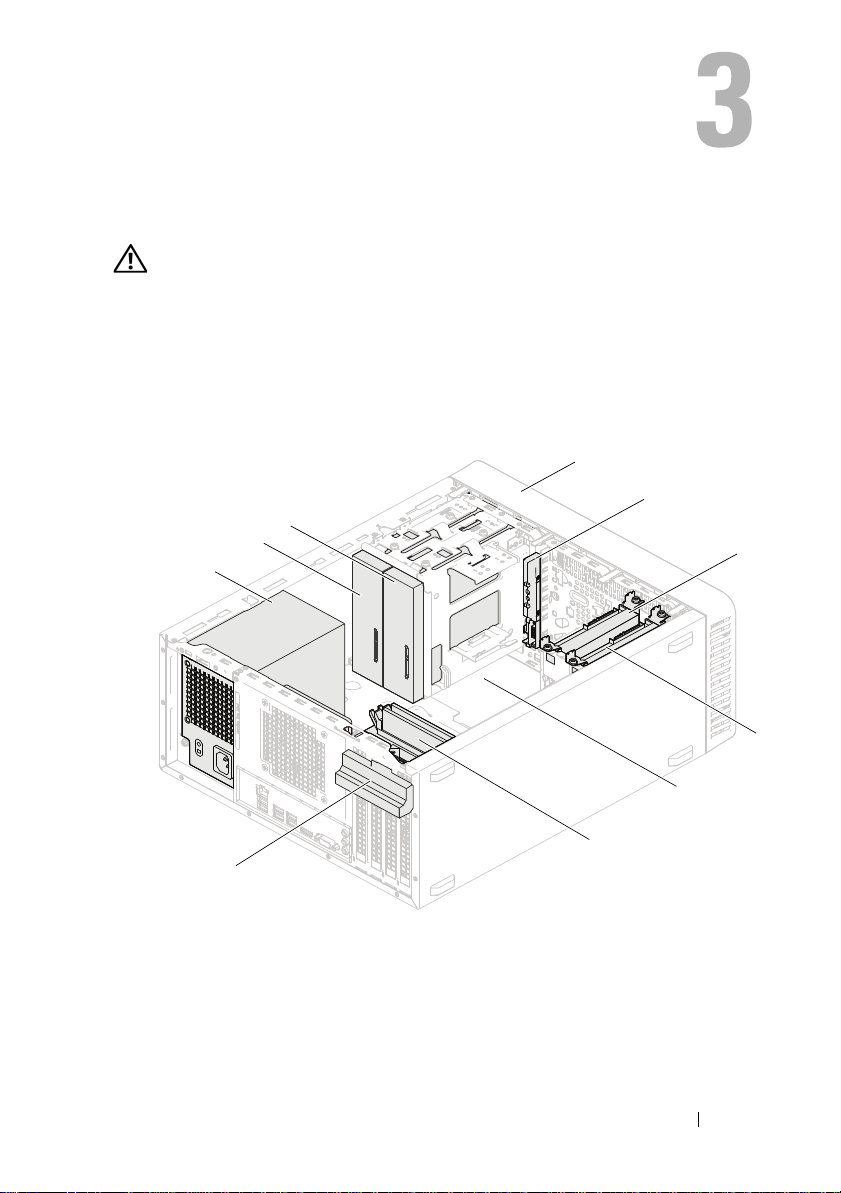
Inside View of Your Computer
1 power supply 2 primary optical-drive
3 secondary optical-drive 4 front bezel
5 front I/O panel 6 primary hard-drive
7 secondary hard-drive 8 system board
9 memory modules 10 card retention bracket
Technical Overview 13
Page 14
System Board Components
1
2
3
4
5
6
9
8
12
1314151617
18
19
20
22
11
21
10
7
23
14 Technical Overview
Page 15

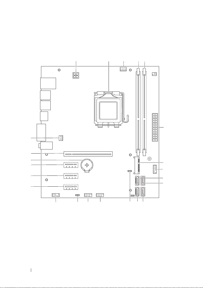
1 power connector (ATX12V) 2 processor socket
3 processor fan connector (FANCPU) 4 memory-module connector (DIMM1)
5 memory-module connector (DIMM2) 6 main power connector (ATX)
7 Mini-Card slot (MINI1) 8 power button connector (LEDH2)
9 SATA connector (SATA 3) 10 SATA connector (SATA 2)
11 SATA connector (SATA 1) 12 SATA connector (SATA 0)
13 CMOS reset jumper (CMOSCLR1) 14 front panel USB connector (USBF2)
15 front panel USB connector (USBF1) 16 password reset jumper (PSWDCLR1)
17 front panel audio connector (AUDIOF1) 18 PCI Express x1 card slot (SLOT4)
19 PCI Express x1 card slot (SLOT3) 20 PCI Express x1 card slot (SLOT2)
21 battery socket (BT1) 22 PCI Express x16 card slot (SLOT1)
23 chassis fan connector (FANSYS4)
Technical Overview 15
Page 16

16 Technical Overview
Page 17

Computer Cover
WARNING: Before working inside your computer, read the safety information that
shipped with your computer and follow the steps in "Before You Begin" on page 9.
For additional safety best practices information, see the Regulatory Compliance
Homepage at dell.com/regulatory_compliance.
CAUTION: Ensure that sufficient space exists to support the computer with the
cover removed—at least 30 cm (1 ft.) of desk top space.
Computer Cover 17
Page 18
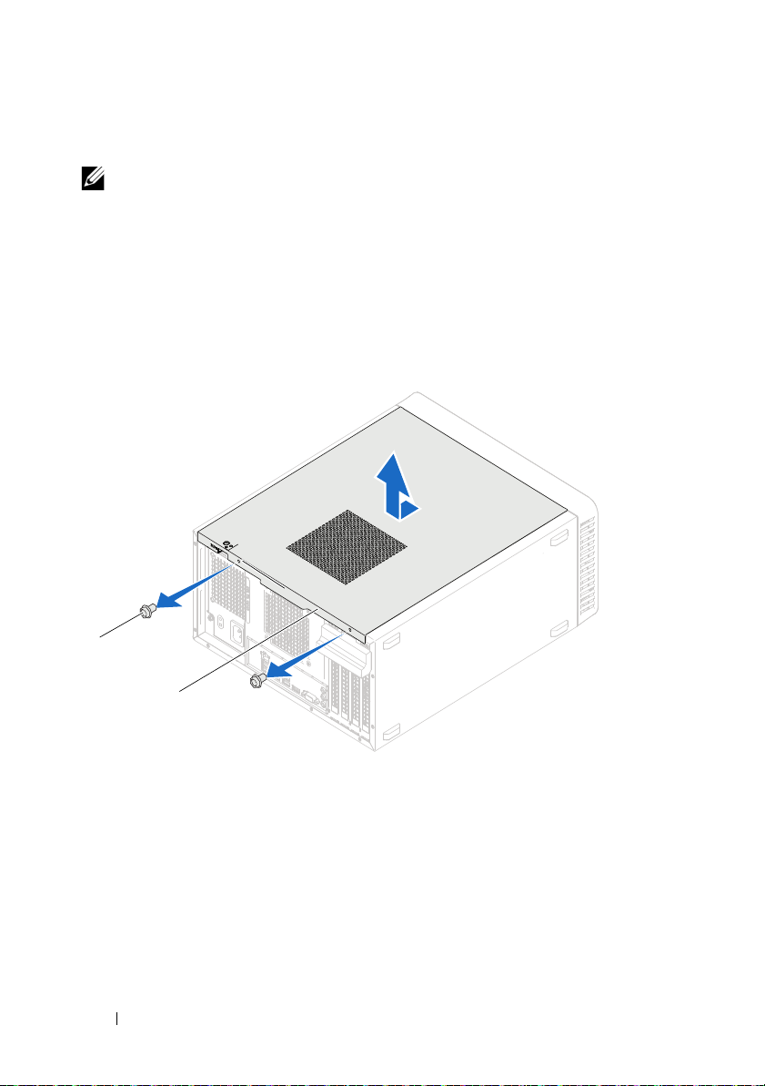
Removing the Computer Cover
2
1
NOTE: Ensure that you remove the padlock from the padlock rings, if applicable.
1
Lay the computer on its side with the computer cover facing up.
2
Using a screwdriver, remove the screws that secure the computer cover to the chassis.
3
Release the computer cover by sliding it away from the front of the computer.
4
Lift the cover away from the computer and set it aside in a secure location.
1 screws (2) 2 computer cover
18 Computer Cover
Page 19
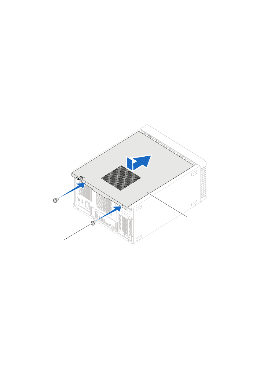
Replacing the Computer Cover
1
2
1
Connect all the cables and fold the cables out of the way.
2
Ensure that no tools or extra parts are left inside the computer.
3
Align the tabs at the bottom of the computer cover with the slots located along the edge of the chassis.
4
Press the computer cover down and slide it towards the front of the computer.
5
Replace the screws that secure the computer cover to the chassis.
1 screws (2) 2 computer cover
6
Place the computer in an upright position.
7
Follow the instructions in "After Working Inside Your Computer" on page 11.
Computer Cover 19
Page 20

20 Computer Cover
Page 21
Memory Module(s)
1
2
WARNING: Before working inside your computer, read the safety information that
shipped with your computer and follow the steps in "Before You Begin" on page 9.
For additional safety best practices information, see the Regulatory Compliance
Homepage at dell.com/regulatory_compliance.
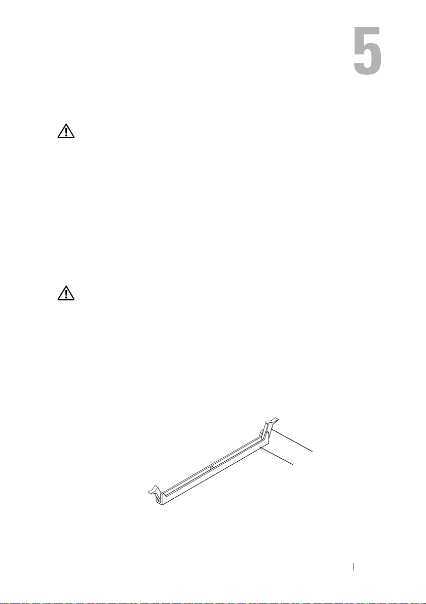
Removing the Memory Module(s)
Prerequisites
Remove the computer cover. See "Removing the Computer Cover" on
page 18.
Procedure
WARNING: The memory module(s) may become very hot during normal operation.
Allow the memory module(s) to cool before touching them.
1
Locate the memory-module connector on the system board. See "System Board Components" on page 14.
2
Press out the securing clip at each end of the memory-module connector.
3
Grasp the memory module and pull it upwards. If the memory module is difficult to remove, gently ease the memory module back and forth to remove it from the connector.
1 memory module connector 2 securing clips (2)
Memory Module(s) 21
Page 22
Replacing the Memory Module(s)
4
3
1
2
CAUTION: If you remove the original memory module(s) from your computer
during a memory upgrade, keep them separate from any new memory module(s)
that you may have, even if you purchased the new memory module(s) from Dell.
If possible, do not pair an original memory module with a new memory module.
Otherwise, your computer may not start properly.
CAUTION: Do not install ECC or DDR3U memory modules.
Procedure
1
Press out the securing clip at each end of the memory module connector.
2
Align the notch on the memory module with the tab in the memory module connector.
1 cutouts (2) 2 tab
3 notch 4 memory module
22 Memory Module(s)
Page 23

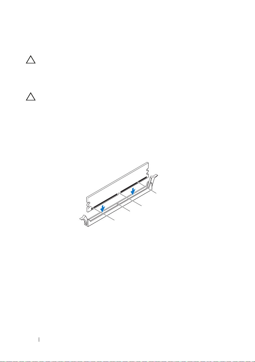
CAUTION: To avoid damage to the memory module, press the memory module
2
1
straight down into the connector while you apply equal force to each end of the
memory module.
3
Insert the memory module into the memory-module connector until the memory module snaps into position and the securing clip locks in place.
If you insert the memory module correctly, the securing clips snap into the
cutouts at each end of the memory module.
1 cutouts (2) 2 securing clips (2) (snapped in position)
Postrequisites
1
Replace the computer cover. See "Replacing the Computer Cover" on page 19.
2
Follow the instructions in "After Working Inside Your Computer" on page 11.
3
Connect your computer and devices to electrical outlets, and then turn them on.
If a message appears stating that the memory size has changed,
press <F1> to continue.
Log on to your computer. To verify that the memory is installed correctly,
click
Start→
Control Panel→
System
. Check the amount of
memory (RAM) listed.
Memory Module(s) 23
Page 24

24 Memory Module(s)
Page 25

Front Bezel
WARNING: Before working inside your computer, read the safety information
that shipped with your computer and follow the steps in "Before You Begin" on
page 9. For additional safety best practices information, see the Regulatory
Compliance Homepage at dell.com/regulatory_compliance.
Removing the Front Bezel
Prerequisites
Remove the computer cover. See "Removing the Computer Cover" on
page 18.
Front Bezel 25
Page 26
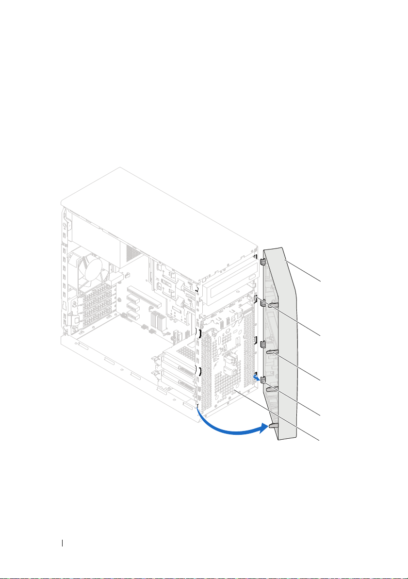
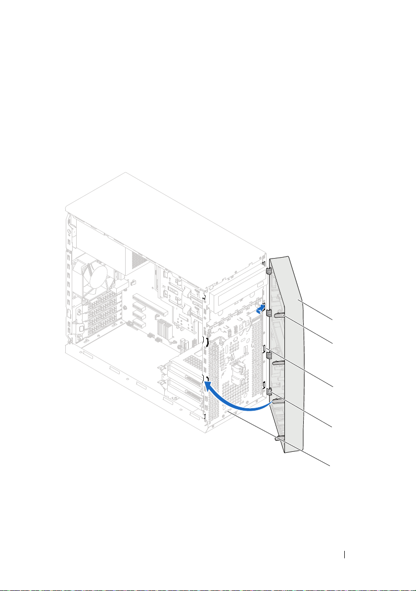
Procedure
3
4
5
1
2
1
Place the computer in an upright position.
2
Grasp and release the front bezel tabs sequentially, one at a time by moving them outward from the front panel.
3
Rotate and pull the front bezel away from the front of the computer to release the front bezel clamps from the front panel slots.
1 front bezel 2 front panel slots (4)
3 front bezel tabs (4) 4 front bezel clamps (4)
5 front panel
4
Set aside the front bezel in a secure location.
26 Front Bezel
Page 27
Replacing the Front Bezel
1
2
3
5
4
Procedure
1
Align and insert the front bezel clamps into the front panel slots.
2
Rotate the front bezel towards the computer until the front bezel tabs snap into place.
1 front bezel 2 front bezel tabs (4)
3 front panel slots (4) 4 front bezel clamps (4)
5 front panel
Front Bezel 27
Page 28

Postrequisites
1
Replace the computer cover. See "Replacing the Computer Cover" on page 19.
2
Follow the instructions in "After Working Inside Your Computer" on page 11.
28 Front Bezel
Page 29

Card Retention Bracket
WARNING: Before working inside your computer, read the safety information
that shipped with your computer and follow the steps in "Before You Begin" on
page 9. For additional safety best practices information, see the Regulatory
Compliance Homepage at dell.com/regulatory_compliance.
Removing the Card Retention Bracket
Prerequisites
Remove the computer cover. See "Removing the Computer Cover" on
page 18.
Card Retention Bracket 29
Page 30
Procedure
1
2
Push the release tab to release the card retention bracket from the chassis.
1 release tab 2 card retention bracket
30 Card Retention Bracket
Page 31

Replacing the Card Retention Bracket
Procedure
Rotate and push the card retention bracket towards the computer until it
snaps into place.
Postrequisites
1
Replace the computer cover. See "Removing the Computer Cover" on page 18.
2
Follow the instructions in "After Working Inside Your Computer" on page 11.
Card Retention Bracket 31
Page 32

32 Card Retention Bracket
Page 33

PCI Express Cards
WARNING: Before working inside your computer, read the safety information
that shipped with your computer and follow the steps in "Before You Begin" on
page 9. For additional safety best practices information, see the Regulatory
Compliance Homepage at dell.com/regulatory_compliance.
Removing PCI Express Cards
Prerequisites.
1
Remove the computer cover. See "Removing the Computer Cover" on page 18.
2
Remove the card retention bracket. See "Removing the Card Retention Bracket" on page 29.
PCI Express Cards 33
Page 34

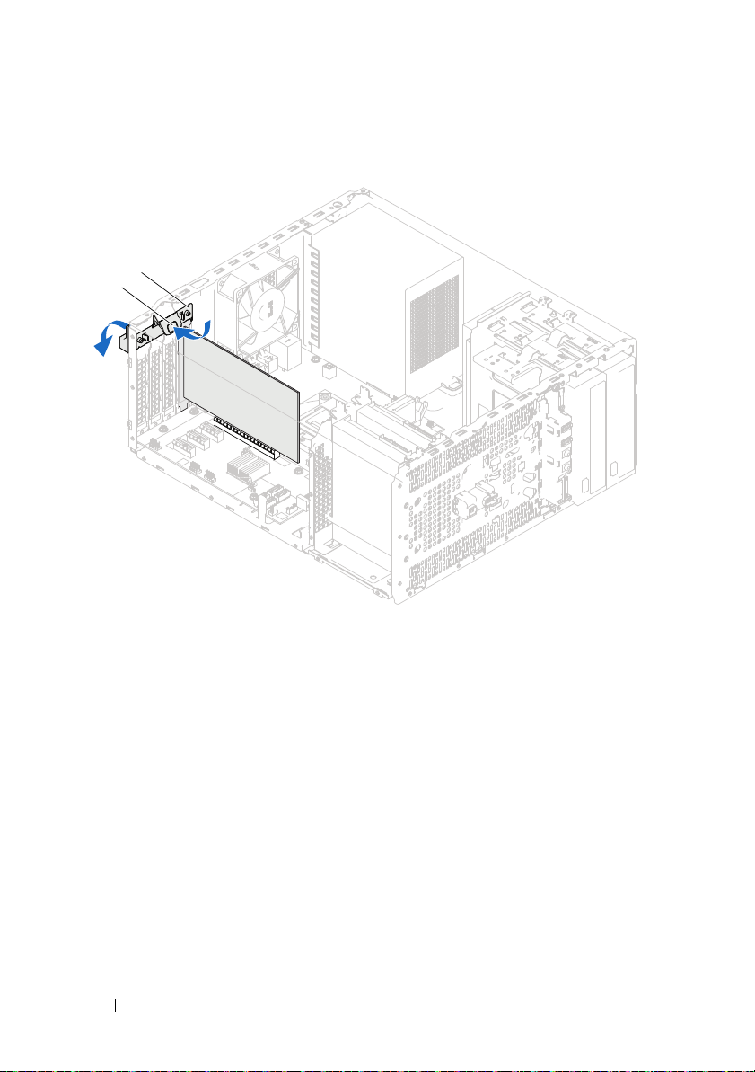
Procedure
1
2
1
3
2
1
Disconnect any cables connected to the card, if applicable.
2
Remove the PCI Express card from the card slot:
PCI Express x1 card
its connector.
1 PCI Express x1 card 2 PCI Express x1 card slot
— Grasp the card by its top corners, and ease it out of
PCI Express x16 card
— Push the securing tab to the side, grasp the card
by its top corners, and then ease it out of the connector.
1 securing tab 2 PCI Express x16 card slot
3 PCI Express x16 card
34 PCI Express Cards
Page 35

3
2
1
If you are removing the card permanently, install a filler bracket in the empty card-slot opening.
NOTE: Installing filler brackets over empty card-slot openings is necessary to
maintain FCC certification of the computer. The brackets also keep dust and dirt out
of your computer.
Replacing PCI Express Cards
Procedure
1
Prepare the card for installation.
See the documentation that shipped with the card for information on
configuring the card, making internal connections, or otherwise
customizing it for your computer.
2
Replace the PCI Express card:
PCI Express x1 card
system board and press down firmly. Ensure that the PCI Express card is
fully seated in the slot.
— Place the PCI Express card in the slot on the
1 PCI Express x1 card 2 PCI Express x1 card slot
PCI Express Cards 35
Page 36

PCI Express x16 card
1
2
3
— Push the securing tab to the side and place the
PCI Express card in the slot on the system board and press down firmly.
Ensure that the PCI Express card is fully seated in the slot.
1 securing tab 2 PCI Express x16 card slot
3 PCI Express x16 card
Postrequisites
1
Replace the card retention bracket. See "Replacing the Card Retention Bracket" on page 31.
2
Connect any cables that should be attached to the card.
See the documentation that shipped with the card for information about
the card’s cable connections.
CAUTION: Do not route card cables over or behind the cards. Cables routed over
the cards can prevent the computer cover from closing properly or cause damage
to the equipment.
3
Replace the computer cover. See "Replacing the Computer Cover" on page 19.
4
Follow the instructions in "After Working Inside Your Computer" on page 11.
5
To complete the installation, see "Configuring Your Computer After Removing or Installing the PCI Express Card" on page 37.
36 PCI Express Cards
Page 37

Configuring Your Computer After Removing or Installing the PCI Express Card
NOTE: For information about the location of external connectors, see the
Quick Start Guide. For information on installing drivers and software for your card,
see the documentation that shipped with the card.
Installed Removed
Sound card 1
Network card 1
Enter system setup. See "System Setup" on page 91.
2
Go to
Onboard Audio
Controller
the setting to
3
Connect the external audio devices to the sound card’s connectors.
Enter system setup. See "System Setup" on page 91.
2
Go to
Controller
the setting to
3
Connect the network cable to the network card’s connector.
and then change
Disabled
Onboard LAN
and then change
Disabled
.
.
1
Enter system setup. See "System Setup" on page 91.
2
Go to
Onboard Audio
Controller
the setting to
3
Connect the external audio devices to the computer’s back panel connectors.
1
Enter system setup. See "System Setup" on page 91.
2
Go to
Controller
the setting to
3
Connect the network cable to the integrated network connector.
and then change
Enabled
Onboard LAN
and then change
Enabled
.
.
PCI Express Cards 37
Page 38

38 PCI Express Cards
Page 39

Mini-Card
WARNING: Before working inside your computer, read the safety information
that shipped with your computer and follow the steps in "Before You Begin" on
page 9. For additional safety best practices information, see the Regulatory
Compliance Homepage at dell.com/regulatory_compliance.
CAUTION: When the Mini-Card is not in the computer, store it in protective
antistatic packaging. See "Protecting Against Electrostatic Discharge" in the
safety instructions that shipped with your computer.
NOTE: Dell does not guarantee compatibility or provide support for Mini-Cards
from sources other than Dell.
If you ordered a wireless Mini-Card with your computer, the card is already
installed.
Your computer supports one half Mini-Card slot for Wireless Local Area
Network (WLAN).
Mini-Card 39
Page 40

Removing the Mini-Card
2
1
3
1
2
Prerequisites
Remove the computer cover. See "Removing the Computer Cover" on
page 18.
Procedure
1
Disconnect the antenna cable(s) from the Mini-Card.
2
Remove the screw that secures the Mini-Card to the system board.
1 antenna cables (2) 2 screw
3
Lift the Mini-Card away from the system-board connector.
1 notch 2 tab
3 Mini-Card
40 Mini-Card
Page 41

Replacing the Mini-Card
CAUTION: The connectors are keyed to ensure correct insertion. Use of
excessive force may damage the connectors.
CAUTION: To avoid damage to the Mini-Card, ensure that there are no cables
under the Mini-Card.
Procedure
1
Align the notch on the Mini-Card with the tab on the
system-board connector.
2
Insert the Mini-Card at a 45-degree angle into the system-board connector.
3
Press the other end of the Mini-Card down into the slot on the
system board and replace the screw that secures the Mini-Card to the
system board.
4
Connect the appropriate antenna cables to the Mini-Card you are
installing. The Mini-Card has two triangles marked on the label
(black and white):
• Connect the black cable to the connector marked with a
black triangle.
• Connect the white cable to the connector marked with a
white triangle.
Postrequisites
1
Replace the computer cover. See "Replacing the Computer Cover" on
page 19.
2
Follow the instructions in "After Working Inside Your Computer" on
page 11.
Mini-Card 41
Page 42

42 Mini-Card
Page 43

Hard Drive(s)
WARNING: Before working inside your computer, read the safety information
that shipped with your computer and follow the steps in "Before You Begin" on
page 9. For additional safety best practices information, see the Regulatory
Compliance Homepage at dell.com/regulatory_compliance.
WARNING: If you remove the hard drive from the computer when the drive is hot,
do not touch the metal housing of the hard drive.
CAUTION: To avoid data loss, do not remove the hard drive while the computer is
On or in Sleep state.
CAUTION: Hard drives are extremely fragile. Exercise care when handling the
hard drive.
Removing the Hard Drive(s)
Prerequisites
Remove the computer cover. See "Removing the Computer Cover" on
page 18.
Hard Drive(s) 43
Page 44

Procedure
1
If you are removing the primary hard-drive, disconnect the power and data cables from the primary hard-drive.
2
If you are removing the secondary hard-drive:
a
Disconnect the power cable from the primary and secondary
hard-drives.
b
Disconnect the data cable from the secondary hard-drive.
NOTE: If you are not replacing the hard drive at this time, disconnect the other end
of the data cable from the system board connector and set it aside. You can use the
data cable to install a hard drive at a later time.
3
Remove the screws that secure the hard-drive assembly to the hard-drive bay.
CAUTION: Ensure that you do not scratch the hard drive’s circuit board, while
removing or replacing the hard drive.
4
Lift the hard-drive assembly away from the computer.
44 Hard Drive(s)
Page 45

Primary Hard-Drive
1
4
3
2
1 primary hard-drive assembly 2 data cable
3 power cable 4 screws (2)
Hard Drive(s) 45
Page 46

Secondary Hard-Drive
1
4
2
3
1 secondary hard-drive assembly 2 data cable
3 power cable 4 screws (2)
46 Hard Drive(s)
Page 47

5
1
2
3
Remove the screws (one on each side) that secure the hard-drive brackets to the hard-drive.
6
Remove the hard-drive brackets off the hard drive.
1 hard drive 2 screws (2)
3 hard-drive bracket
7
If removing the hard drive changes the drive configuration, ensure that you reflect these changes in system setup. See "System Setup" on page 91.
Hard Drive(s) 47
Page 48

Replacing the Hard Drive(s)
Procedure
1
Check the documentation that shipped with the hard drive to verify that it is configured for your computer.
2
Place the hard-drive brackets in position and replace the screws (one on each side) that secure the hard-drive brackets to the hard drive.
3
Slide the hard-drive assembly into the hard-drive bay.
4
Replace the screws that secure the hard-drive assembly to the hard-drive bay.
5
If you are replacing the primary hard-drive, connect the power and data cables to the primary hard drive.
6
If you are replacing the secondary hard-drive:
a
Connect the power cable to the primary and secondary hard-drives.
b
Connect the data cable to the secondary hard-drive.
Postrequisites
1
Replace the computer cover. See "Replacing the Computer Cover" on page 19.
2
Follow the instructions in "After Working Inside Your Computer" on page 11.
48 Hard Drive(s)
Page 49

Optical Drive(s)
WARNING: Before working inside your computer, read the safety information
that shipped with your computer and follow the steps in "Before You Begin" on
page 9. For additional safety best practices information, see the Regulatory
Compliance Homepage at dell.com/regulatory_compliance.
Removing the Optical Drive(s)
Prerequisites
1
Remove the computer cover. See "Removing the Computer Cover" on
page 18.
2
Remove the front bezel. See "Removing the Front Bezel" on page 25.
Optical Drive 49
Page 50

Procedure
1
If you are removing the primary optical-drive, disconnect the power and
data cables from the primary optical-drive.
2
If you are removing the secondary optical-drive:
a
Disconnect the power cable from the primary and secondary
optical-drives.
b
Disconnect the data cable from the secondary optical-drive.
NOTE: If you are not replacing the optical drive at this time, disconnect the other
end of the data cable from the system board connector and set it aside. You can use
the data cable to install an optical drive at a later time.
3
Remove the screws that secure the optical drive to the chassis.
4
Push and slide the optical drive out through the front of the computer.
50 Optical Drive
Page 51

Primary Optical-Drive
4
1
2
3
1 power cable 2 data cable
3 primary optical-drive 4 screws (2)
Optical Drive 51
Page 52

Secondary Optical-Drive
1
2
3
4
1 power cable 2 data cable
3 secondary optical-drive 4 screws (2)
5
52 Optical Drive
Set aside the optical drive in a secure location.
Page 53

Replacing the Optical Drives(s)
1
Procedure
1
Remove the screw from the optical drive you removed and insert it in the
new optical drive.
1 screw
Optical Drive 53
Page 54

2
1
To install a secondary optical drive, pull the break-away metal plate off the
chassis.
1 break-away metal plate
3
Gently slide the optical drive into the optical drive bay through the front
of the computer.
4
Align the screw holes on the optical drive with the screw holes on the
chassis.
5
Replace the screws that secure the optical drive to the chassis.
54 Optical Drive
Page 55

6
If you are replacing the primary optical-drive, connect the power and data
cables to the primary optical-drive.
7
If you are replacing the secondary optical-drive:
a
Connect the power cable to the primary and secondary optical-drives.
b
Connect the data cable to the secondary optical-drive.
Postrequisites
1
Replace the computer cover. See "Replacing the Computer Cover" on
page 19.
2
Replace the front bezel. See "Replacing the Front Bezel" on page 27.
3
Follow the instructions in "After Working Inside Your Computer" on
page 11.
Optical Drive 55
Page 56

56 Optical Drive
Page 57

Front I/O Panel
WARNING: Before working inside your computer, read the safety information
that shipped with your computer and follow the steps in "Before You Begin" on
page 9. For additional safety best practices information, see the Regulatory
Compliance Homepage at dell.com/regulatory_compliance.
Removing the Front I/O Panel
Prerequisites
1
Remove the computer cover. See "Removing the Computer Cover" on page 18.
2
Remove the front bezel. See "Removing the Front Bezel" on page 25.
Front I/O Panel 57
Page 58

Procedure
1
2
NOTE: Make note of the routing of all cables as you remove them so that you can
re-route them correctly when installing the new front I/O panel.
1
Disconnect the front I/O panel cables from the system board connectors (AUDIOF1, USBF1, and USBF2). See "System Board Components" on page 14.
2
Remove the screws that secure the front I/O panel to the front panel.
3
Slide the front I/O panel towards the side as shown in the illustration to release the clamps from the front panel and pull it away.
1 screws (2) 2 front I/O panel
58 Front I/O Panel
Page 59

Replacing the Front I/O Panel
Procedure
CAUTION: To avoid damage to the cable connectors and the cable routing clips,
carefully slide the front I/O panel into the front I/O panel clamp slot.
1
Align and slide the front I/O panel clamps into the slots on the front panel.
2
Replace the screws that secure the front I/O panel to the front panel.
3
Connect the front I/O panel cables to the system board connectors (AUDIOF1, USBF1, and USBF2). See "System Board Components" on page 14.
Postrequisites
1
Replace the front bezel see "Replacing the Front Bezel" on page 27.
2
Replace the computer cover. See "Replacing the Computer Cover" on page 19.
3
Follow the instructions in "After Working Inside Your Computer" on page 11.
Front I/O Panel 59
Page 60

60 Front I/O Panel
Page 61

Power Button Module
WARNING: Before working inside your computer, read the safety information
that shipped with your computer and follow the steps in "Before You Begin" on
page 9. For additional safety best practices information, see the Regulatory
Compliance Homepage at dell.com/regulatory_compliance.
Removing the Power Button Module
Prerequisites
1
Remove the computer cover. See "Removing the Computer Cover" on page 18.
2
Remove the front bezel. See "Removing the Front Bezel" on page 25.
Power Button Module 61
Page 62

Procedure
1
2
1
Disconnect the power button module cable from the system board connector (LEDH2). See "System Board Components" on page 14.
2
Press the power button module tabs and pull the power button module to release it from the front panel.
1 power button module 2 power button module tabs (4)
3
Set aside the power button module in a secure location.
62 Power Button Module
Page 63

Replacing the Power Button Module
Procedure
1
Align and push the power button module tabs into the slots on the front panel.
2
Connect the power button module cable to the system board connector (LEDH2). See "System Board Components" on page 14.
Postrequisites
1
Replace the front bezel. See "Replacing the Front Bezel" on page 27.
2
Replace the computer cover. See "Replacing the Computer Cover" on page 19.
3
Follow the instructions in "After Working Inside Your Computer" on page 11.
Power Button Module 63
Page 64

64 Power Button Module
Page 65

Chassis Fan
WARNING: Before working working inside your computer, read the safety
information that shipped with your computer and follow the steps in "Before You
Begin" on page 9. For additional safety best practices information, see the
Regulatory Compliance Homepage at dell.com/regulatory_compliance.
Removing the Chassis Fan
Prerequisites
Remove the computer cover. See "Removing the Computer Cover" on
page 18.
Chassis Fan 65
Page 66

Procedure
1
2
1
Disconnect the chassis fan cable from the system board connector
(
FANSYS4)
2
Remove the screws that secure the chassis fan to the chassis.
3
Slide and lift the chassis fan away from the computer as shown in the illustration.
. See "System Board Components" on page 14.
1 screws (4) 2 chassis fan
66 Chassis Fan
Page 67

Replacing the Chassis Fan
Procedure
1
Align the screw holes on the chassis fan with the screw holes on the chassis.
2
Replace the screws that secure the chassis fan to the chassis.
3
Connect the chassis fan cable to the system board connector (
See "System Board Components" on page 14.
Postrequisites
Replace the computer cover. See "Replacing the Computer Cover" on
page 19.
FANS YS 4)
.
Chassis Fan 67
Page 68

68 Chassis Fan
Page 69

Processor Fan and Heat-Sink Assembly
WARNING: Before working inside your computer, read the safety information
that shipped with your computer and follow the steps in "Before You Begin" on
page 9. For additional safety best practices information, see the Regulatory
Compliance Homepage at dell.com/regulatory_compliance.
Removing the Processor Fan and Heat-Sink Assembly
Prerequisites
Remove the computer cover. See "Removing the Computer Cover" on
page 18.
Processor Fan and Heat-Sink Assembly 69
Page 70

Procedure
1
2
3
WARNING: Despite having a plastic shield, the processor fan and heat-sink
assembly may be very hot during normal operation. Ensure that it has had
sufficient time to cool before you touch it.
CAUTION: The processor fan and heat-sink assembly is a single unit. Do not try to
remove the fan separately.
CAUTION: To ensure maximum cooling for the processor, do not touch the heat
transfer areas on the processor fan and heat-sink assembly. The oils in your skin
can reduce the heat transfer capability of the thermal grease.
1
Disconnect the processor fan cable from the system board connector
(
FANC PU)
2
Using a flat-blade screwdriver loosen the captive screws that secure the processor fan and heat-sink assembly to the system board.
3
Lift the processor fan and heat-sink assembly out of the computer.
. See "System Board Components" on page 14.
1 processor fan cable 2 processor fan and heat-sink assembly
3 captive screws (4)
70 Processor Fan and Heat-Sink Assembly
Page 71

Replacing the Processor Fan and Heat-Sink Assembly
Procedure
CAUTION: Ensure that you apply new thermal grease. New thermal grease is
critical for ensuring adequate thermal bonding, which is a requirement for optimal
processor operation
CAUTION: Incorrect alignment of the processor fan and heat-sink assembly can
damage the system board and processor
NOTE: The original thermal grease can be reused if the original processor and
processor fan and heat-sink assembly are reinstalled together. If either the
processor or the processor fan and heat-sink assembly is replaced, use the thermal
grease provided in the kit to ensure that thermal conductivity is achieved.
1
Apply new thermal grease to the top of the processor.
2
Place the processor fan and heat-sink assembly over the processor.
3
Align the captive screws on the processor fan and heat-sink assembly with the screw holes on the system board.
4
Tighten the captive screws that secure the processor fan and heat-sink assembly to the system board.
5
Connect the processor fan cable to the system board connector
FANC PU)
(
. See "System Board Components" on page 14.
Postrequisites
1
Replace the computer cover. See "Replacing the Computer Cover" on page 19.
2
Follow the instructions in "After Working Inside Your Computer" on page 11.
Processor Fan and Heat-Sink Assembly 71
Page 72

72 Processor Fan and Heat-Sink Assembly
Page 73

Processor
WARNING: Before working inside your computer, read the safety information that
shipped with your computer and follow the steps in "Before You Begin" on page 9.
For additional safety best practices information, see the Regulatory Compliance
Homepage at dell.com/regulatory_compliance.
Removing the Processor
Prerequisites
1
Remove the computer cover. See "Removing the Computer Cover" on
page 18.
WARNING: Despite having a plastic shield, the processor fan and heat-sink
assembly may be very hot during normal operation. Ensure that it has had
sufficient time to cool before you touch it.
2
Remove the processor fan and heat-sink assembly from the computer.
See "Removing the Processor Fan and Heat-Sink Assembly" on page 69.
Processor 73
Page 74

Procedure
1
3
2
1
Press down and push the release lever away from the processor to release it
from the securing tab.
2
Extend the release lever completely to open the processor cover.
1 processor cover 2 tab 3 release lever
CAUTION: When removing the processor, do not touch any of the pins inside the
socket or allow any objects to fall on the pins in the socket.
3
Open the processor cover and gently lift the processor from the
processor socket.
Leave the release lever extended in the release position so that the socket is
ready for the new processor.
74 Processor
Page 75

Replacing the Processor
1
3
5
4
2
Procedure
1
Unpack the new processor, being careful not to touch the underside of
the processor.
CAUTION: You must position the processor correctly in the processor socket to
avoid damage to the processor.
2
If the release lever on the socket is not fully extended, move it to that
position.
3
Orient the alignment notches on the processor with the alignment tabs on
the socket.
4
Align the pin-1 corner of the processor with the pin-1 corner of the
processor socket, and then place the processor in the processor socket.
Set the processor lightly in the socket and ensure that the processor is
positioned correctly.
1 socket 2 processor 3 alignment tabs (2)
4 alignment notches (2) 5 processor pin-1 indicator
Processor 75
Page 76

CAUTION: Ensure that the processor cover notch is positioned underneath the
3
4
6
5
1
2
alignment post.
5
When the processor is fully seated in the socket, close the processor cover.
6
Pivot the release lever down and place it under the tab on the
processor cover.
1 alignment post 2 tab 3 processor cover
4 release lever 5 processor 6 processor cover notch
Postrequisites
1
Replace the processor fan and heat-sink assembly. See "Replacing the
Processor Fan and Heat-Sink Assembly" on page 71.
2
Replace the computer cover. See "Replacing the Computer Cover" on
page 19.
3
Follow the instructions in "After Working Inside Your Computer" on
page 11.
76 Processor
Page 77

Coin-Cell Battery
WARNING: Before working inside your computer, read the safety information
that shipped with your computer and follow the steps in "Before You Begin" on
page 9. For additional safety best practices information, see the Regulatory
Compliance Homepage at dell.com/regulatory_compliance.
WARNING: A battery may explode if installed incorrectly. Replace the battery
only with the same or equivalent type. Discard used batteries according to the
manufacturer’s instructions.
CAUTION: Removing the coin-cell battery resets the BIOS settings to default. It is
recommended that you note the BIOS settings before removing the
coin-cell battery. See "System Setup" on page 91 for instructions on entering the
system setup program.
Removing the Coin-Cell Battery
Prerequisites
Remove the computer cover. See "Removing the Computer Cover" on
page 18.
Coin-Cell Battery 77
Page 78

Procedure
3
2
1
1
Locate the battery socket. See "System Board Components" on page 14.
2
Press the battery-release lever away from the battery until the coin-cell battery pops up.
1 battery-release lever 2 coin-cell battery
3 battery socket
3
Set aside the battery in a secure location.
78 Coin-Cell Battery
Page 79

Replacing the Coin-Cell Battery
2
1
Procedure
Insert the battery (CR2032) into the socket with the side labeled "+" facing
up, and press down the battery in the socket.
1 coin-cell battery 2 battery socket
Postrequisites
1
Replace the computer cover. See "Replacing the Computer Cover" on page 19.
2
Follow the instructions in "After Working Inside Your Computer" on page 11.
3
Enter the system setup program and set the time and date. See "Entering System Setup" on page 91.
4
Update the BIOS settings with values you may have noted before removing the coin-cell battery. See "Entering System Setup" on page 91.
Coin-Cell Battery 79
Page 80

80 Coin-Cell Battery
Page 81

Power Supply
WARNING: Before working inside your computer, read the safety information
that shipped with your computer and follow the steps in "Before You Begin" on
page 9. For additional safety best practices information, see the Regulatory
Compliance Homepage at dell.com/regulatory_compliance.
Removing the Power Supply
Prerequisites
Remove the computer cover. See "Removing the Computer Cover" on
page 18.
Power Supply 81
Page 82

Procedure
1
2
3
1
Disconnect the DC power cables from the system board and the drives. See "System Board Components" on page 14.
2
Remove the screws that secure the power supply to the chassis.
3
Press the power supply clamp to release the power supply from the chassis.
4
Slide and lift the power supply away from the chassis.
1 screws (4) 2 power supply
3 power supply clamp
82 Power Supply
Page 83

Replacing the Power Supply
Procedure
1
Slide the power supply towards the back of the chassis.
2
Align the screw holes on the power supply with the screw holes on the chassis.
3
Replace the screws that secure the power supply to the chassis.
4
Connect the DC power cables to the system board and drives. See "System Board Components" on page 14.
Postrequisites
1
Replace the computer cover. See "Replacing the Computer Cover" on page 19.
2
Follow the instructions in "After Working Inside Your Computer" on page 11.
Power Supply 83
Page 84

84 Power Supply
Page 85

System Board
WARNING: Before working inside your computer, read the safety information
that shipped with your computer and follow the steps in "Before You Begin" on
page 9. For additional safety best practices information, see the Regulatory
Compliance Homepage at dell.com/regulatory_compliance.
Removing the System Board
Prerequisites
1
Remove the computer cover. See "Removing the Computer Cover" on page 18.
2
Remove the Mini-Card, if applicable. See "Removing the Mini-Card" on page 40.
3
Remove the any PCI-Express cards, if applicable. See "Removing PCI Express Cards" on page 33.
4
Remove the processor fan and heat-sink assembly. See "Removing the Processor Fan and Heat-Sink Assembly" on page 69.
5
Remove the processor. See "Removing the Processor" on page 73.
6
Remove the memory modules. See "Removing the Memory Module(s)" on page 21. Record which memory module is removed from each DIMM slot so that the memory modules can be installed in the same slot after the system board is replaced.
System Board 85
Page 86

Procedure
1
2
1
Disconnect all cables connected to the system board. See "System Board Components" on page 14. Note the routing of all cables as you remove them so that you can re-route them correctly after installing the new system board.
2
Remove the screws that secure the system board to the chassis.
1 screws (6) 2 system board
3
Lift the system board up and out of the chassis.
86 System Board
Page 87

4
Compare the system board that you removed with the replacement system board to ensure that they are identical.
NOTE: Some components and connectors on the replacement system board
may be in different locations compared to the components and connectors on
the existing system board.
NOTE: Jumper settings on the replacement system board is preset at the
factory.
Replacing the System Board
Procedure
1
Gently place the system board into the chassis and slide it towards the back of the computer.
2
Replace the screws that secure the system board to the chassis.
3
Route and connect the cables that you disconnected from the system board.
NOTE: For information on system board connectors, see "System Board
Components" on page 14.
Postrequisites
1
Replace the processor. See "Replacing the Processor" on page 75.
2
Replace the processor fan and heat-sink assembly. See "Replacing the Processor Fan and Heat-Sink Assembly" on page 71.
3
Replace the memory module(s). See "Replacing the Memory Module(s)" on page 22.
4
Replace any PCI-Express cards, if applicable. See "Replacing PCI Express Cards" on page 35.
5
Replace the Mini-Card, if applicable. See "Replacing the Mini-Card" on page 41.
6
Replace the computer cover. See "Replacing the Computer Cover" on page 19.
7
Follow the instructions in "After Working Inside Your Computer" on page 11.
System Board 87
Page 88

Entering the Service Tag in the BIOS
1
Turn on the computer.
2
Press <F2> during POST to enter the system setup program.
3
Navigate to the main tab and enter the Service Tag in the
Service Tag Input
NOTE: The Service Tag Input field allows you to enter the Service Tag manually
only when the Service Tag is absent.
field.
88 System Board
Page 89

System Board 89
Page 90

90 System Board
Page 91

System Setup
Overview
Use the system setup to:
• Get information about the hardware installed on your computer, such as
the amount of RAM, the size of the hard drive, and so on
• Change the system configuration information
• Set or change a user-selectable option, such as the user password, type of
hard drive installed, enabling or disabling base devices, and so on
CAUTION: Unless you are an expert computer user, do not change the settings for
this program. Certain changes can make your computer work incorrectly.
NOTE: Before you change system setup, it is recommended that you note the
system-setup screen information for future reference.
Entering System Setup
1
Turn on (or restart) your computer.
2
During POST, when the DELL logo is displayed, watch for the F2 prompt
to appear and then press <F2> immediately.
NOTE: The F2 prompt indicates that the keyboard has initialized. This prompt
can appear very quickly, so you must watch for it, and then press <F2>. If you
press <F2> before the F2 prompt, this keystroke is lost. If you wait too long and
the operating system logo appears, continue to wait until you see the
Microsoft Windows desktop. Then, turn off your computer and try again.
See "Turn Off Your Computer and Connected Devices" on page 9.
System Setup 91
Page 92

System Setup Screens
The system setup screen displays current or changeable configuration
information for your computer. Information on the screen is divided into
three areas: the setup item, active help screen, and key functions.
Setup Item — This field appears
on the left side of the system setup
window. The field is a scrollable list
containing features that define the
configuration of your computer,
including installed hardware,
power conservation, and security
features.
Scroll up and down the list with
the up- and down-arrow keys. As
an option is highlighted, the Help
Screen displays more information
about that option and available
Help Screen — This field appears on
the right side of the system setup
window and contains information
about each option listed in the Setup
Item. In this field you can view
information about your computer and
make changes to your current settings.
Press the up- and down-arrow keys to
highlight an option. Press <Enter> to
make that selection active and return
to the Setup Item.
NOTE:
Not all settings listed in the Setup
Item are changeable.
settings.
Key Functions — This field appears below the Help Screen and lists keys
and their functions within the active system setup field.
92 System Setup
Page 93

System Setup Options
NOTE: Depending on your computer and installed devices, the items listed in this
section may appear, or may not appear exactly as listed.
Main — System Information
BIOS Revision Displays the BIOS Revision number
BIOS Build Date Displays the build date in mm/dd/yyyy
format
System Name Displays system name
System Time Displays the current time in hh:mm:ss
format
System Date Displays the current date in mm/dd/yyyy
format
Service Tag Displays the Service Tag of the computer
when the Service Tag is present
Displays a field to input the Service Tag
manually when the Service Tag is absent
Asset Tag Displays the asset tag of the computer
when the asset tag is present.
Main — Processor Information
Processor Type Displays the processor type
Processor ID Displays the processor ID
Processor Core Count Displays the processor nominal cores
Processor L1 Cache Displays the processor L1 cache size
Processor L2 Cache Displays the processor L2 cache size
Processor L3 Cache Displays the processor L3 cache size
Main — Memory Information
Memory Installed Indicates the amount of memory installed
in MB
Memory Running Speed Indicates the memory speed in MHz
Memory Technology Indicates the type of installed memory
System Setup 93
Page 94

Main — SATA Information
SATA 1
Device Type
Device ID
Device Size
SATA 2
Device Type
Device ID
Device Size
SATA 3
Device Type
Device ID
Device Size
SATA 4
Device Type
Device ID
Device Size
Displays the type of device installed on
the SATA1 connector
Displays the serial number of the
device installed
Displays the size of the device installed, if
the device is a hard drive
Displays the type of device installed on
the SATA2 connector
Displays the serial number of the
device installed
Displays the size of the device installed, if
the device is a hard drive
Displays the type of device installed on
the SATA3 connector
Displays the serial number of the
device installed
Displays the size of the device installed, if
the device is a hard drive
Displays the type of device installed on
the SATA4 connector
Displays the serial number of the
device installed
Displays the size of the device installed, if
the device is a hard drive
94 System Setup
Page 95

Advanced — CPU Feature
Intel Hyper-Threading
Technology
Intel(R) SpeedStep Technology Allows you to enable or disable the Intel
Intel(R) Virtualization
Technology
CPU XD Support Allows you to enable or disable the
Limit CPUID Value Allows you to limit the maximum value
Multi Core Support Allows you to specify if processor will have
Intel(R) Turbo Boot
Technology
Allows you to enable or disable the Intel
Hyper-Threading feature for the processor
Enabled or Disabled (Enabled by default)
SpeedStep feature for the processor
Enabled or Disabled (Enabled by default)
Allows you to enable or disable the
Intel virtualization feature for the
processor
Enabled or Disabled (Enabled by default)
execute disable mode for the processor
Enabled or Disabled (Enabled by default)
the processor standard CPUID function
will support
Enabled or Disabled (Disabled by
default)
either one or all cores enabled
Enabled or Disabled (Enabled by default)
Enabled - all cores; Disabled - one core
only
Allows you to enable or disable the Intel
turbo boot technology mode for the
processor
Enabled or Disabled (Enabled by default)
System Setup 95
Page 96

Advanced — USB Configuration
Front USB Ports Allows you to enable or disable the front USB ports
on your computer
Enabled or Disabled (Enabled by default)
Rear USB Ports Allows you to enable or disable the rear USB ports
on your computer
Enabled or Disabled (Enabled by default)
Advanced — Onboard Device Configuration
Onboard Audio
Controller
SATA Mode Allows you to configure the operating mode of the
Allows you to enable or disabled the
audio controller
Enabled or Disable (Enabled by default)
integrated hard-drive controller
ATA Mode; AHCI Mode (AHCI Mode by default)
CAUTION: Changing the SATA Mode may prevent
booting of your operating system.
Onboard LAN Controller Allows you to enable or disable the onboard
LAN controller
Enabled or Disabled (Enabled by default)
Onboard LAN boot ROM Allows you to boot your computer from a network
Enabled or Disabled (Disabled by default)
Boot
Numlock Key Allows you to set the status of the Num Lock key
during boot
On or Off (On by default)
Keyboard Errors Allows you to enable or disable the display of
keyboard-related errors during boot
Report or Do Not Report (Report by default)
96 System Setup
Page 97

Boot (continued)
USB Boot Support Allows you to enable or disable booting from USB
mass storage devices such as hard drive, optical
drive, USB key, and so on.
Enabled or Disabled (Disabled by default)
Boot Mode Specifies the boot sequence from the
available devices
1st Boot Displays the first boot device
2nd Boot
3rd Boot
4th Boot
5th Boot
Power
Wake Up by Integrated
LAN/WLAN
AC Recovery Allows you to configure the behavior of your
Auto Power On Allows you to enable or disable the computer from
Auto Power On Mode Allows you to set the computer to turn on
Displays the second boot device
Displays the third boot device
Displays the fourth boot device
Displays the fifth boot device
Allow the computer to be powered on by
special LAN or wireless LAN signals
Enabled or Disabled (Disabled by default)
computer after it recovers from a power failure
Power Off, Power On, or Last Power State
(Power Off by default)
turning on automatically
Enabled or Disabled (Disabled by default)
automatically every day or on a preselected date;
This option can be configured only if the Auto
Power On mode is set to Enabled
Everyday or Selected Day (Selected Day by default)
System Setup 97
Page 98

Power (continued)
Auto Power On Date Allows you to set the date on which the computer
must turn on automatically; This option can be
configured only if the Auto Power On mode is set to
Enabled
1 to 31 (15 by default)
Auto Power On Time Allows you to set the time at which the computer
must turn on automatically; This option can be
configured only if the Auto Power On mode is set to
Enabled
hh:mm:ss (12:30:30 by default)
Security
Supervisor Password Displays the status of the supervisor password
User Password Displays the status of the user password
Set Supervisor
Password
User Access Level Allows you to set access levels to the users
Set User Password Allows you to set, change, or delete the
Password Check Allows you to enable password verification either
Allows you to set, change, or delete the
supervisor password
No Access, View Only, Limited, or Full Access
(Full Access by default)
• No Access: Restricts users from editing
system setup options
• View Only: Allows users to only view system
setup options
• Limited: Allows users to edit certain system
setup options
• Full Access: Allows users to edit all system
setup options except the Supervisor Password
user password
when you attempt to enter system setup or each
time the computer boots
Setup or Always (Setup by default)
98 System Setup
Page 99

Exit
Save Changes and Reset Allows you to save changes and exit system setup
Discard Changes and
Reset
Load Default Allows you to restore the default settings
Allows you to discard changes and exit system setup
System Setup 99
Page 100

Boot Sequence
This feature allows you to change the boot sequence for devices.
Boot Options
•
USB Floppy —
drive. If no operating system is on the floppy disk, the computer generates
an error message.
•
Hard Drive
drive. If no operating system is on the drive, the computer generates an
error message.
•
CD/DVD/CD-RW Drive
CD/DVD/CD-RW drive. If no CD/DVD/CD-RW is in the drive, or if the
CD/DVD/CD-RW has no operating system, the computer generates an
error message.
•
USB Storage Device
restart the computer. When
lower-right corner of the screen, press <F12>. The BIOS detects the
device and adds the USB flash option to the boot menu.
NOTE: To boot to a USB device, the device must be bootable. To ensure that
your device is bootable, check the device documentation.
•
Network
— The computer attempts to boot from the network. If no
operating system is found on the network, the computer generates an error
message.
The computer attempts to boot from the USB floppy
— The computer attempts to boot from the primary hard
— The computer attempts to boot from the
— Insert the memory device into a USB port and
F12 Boot Options
appears in the
NOTE: To boot from the network, ensure that the Onboard LAN Boot
option is enabled in system setup. See "System Setup" on page 91.
ROM
100 System Setup
 Loading...