

Page 1

Dell™ PowerEdge™ 650 Systems
Replacing the System and
Backplane Board
Assemblies
www.dell.com | support.dell.com
Page 2

Notes, Notices, and Cautions
NOTE: A NOTE indicates important information that helps you make better use of your computer.
NOTICE: A NOTICE indicates either potential damage to hardware or loss of data and tells you how to
avoid the problem.
CAUTION: A CAUTION indicates a potential for property damage, personal injury, or death.
Abbreviations and Acronyms
For a complete list of abbreviations and acronyms, see the
____________________
Installation and Troubleshooting Guide
.
Information in this document is subject to change without notice.
© 2003 Dell Inc. All rights reserved.
Reproduction in any manner whatsoever without the written permission of Dell Inc. is strictly forbidden.
Trademarks used in this text: Dell, the DELL logo, and Pow er Ed ge are trademarks of Dell Inc.
Other trademarks and trade names may be used in this document to refer to either the entities claiming the marks and names or
their products. Dell Inc. disclaims any proprietary interest in trademarks and trade names other than its own.
September 2003 P/N G3929 Rev. A00
Page 3
The system board and backplane board are removed from the chassis as a single assembly, and are
then separated for replacement of either board.
Removing the System Board/Backplane Board Assembly
CAUTION: See your System Information Guide for complete information about safety precautions,
working inside the computer, and protecting against electrostatic discharge.
NOTE: It is not necessary to remove the hard drives or the CD/diskette drive from the system during this
procedure.
To remove the system board/backplane board assembly, perform the following steps:
1
Turn off the system and attached peripherals, and disconnect the system from the electrical
outlet.
2
Open the system. See "Opening the System" in your
3
If you are replacing the system board, remove the system battery. See "Replacing the Battery"
in your
4
If you are replacing the system board, remove the heat sink and processor. See "Replacing the
Processor" in your
5
If you are replacing the system board, remove the memory modules. See "Removing Memory
Modules" in your
6
Remove the cooling shrouds.
7
Disconnect the control panel cable from the J3 connector on the backplane board. See
Installation and Troubleshooting Guide
Installation and Troubleshooting Guide
Installation and Troubleshooting Guide
"Removing the Control Panel Assembly" in your
8
Disconnect the power and interface cables on both hard drives from the backplane board
(connectors JP1, JP2, IDE0 and IDE1).
9
Disconnect the power supply cable from the back of the backplane board (connector J2). See
"Replacing the Power Supply" in your
10
If the hard-drive interface cables are routed through the backplane to a PCI controller card,
Installation and Troubleshooting Guide
disconnect these interface cables from the PCI controller card.
11
Remove all PCI expansion cards installed on the riser board. See "Removing an Expansion
Card" in your
12
Disconnect the CD/diskette drive interface cable from the backplane connector CN1.
13
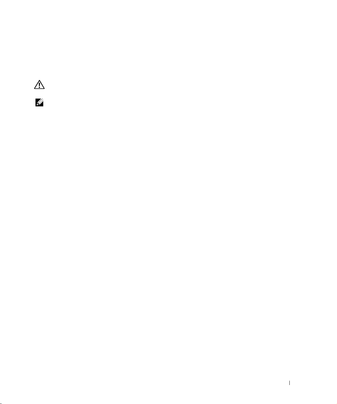
Rotate the backplane release latches up. See Figure 1-1.
14
Remove the power supply. See "Replacing the Power Supply" in your
Troubleshooting Guide
15
Remove the fan assemblies. See "Fan Assemblies" in your
.
Guide
16
Loosen the thumbscrew securing the system board to the chassis floor.
Installation and Troubleshooting Guide
.
Installation and Troubleshooting Guide
.
.
.
Installation and Troubleshooting Guide
.
.
Installation and
Installation and Troubleshooting
.
.
Replacing the System and Backplane Board Assemblies 3
Page 4
17
Loosen the two thumbscrews securing the riser board and disconnect it from the system
board card-edge connector. See "Removing the Riser Board" in your
Troubleshooting Guide.
18
Slide the backplane securing latch forward to the open position to allow the system
board/backplane board to move to the forward (unlatched) position.
19
Slide the system board/backplane board assembly forward, toward the front of the system and
lift the assembly up and out of the chassis. See Figure 1-1.
Figure 1-1. Removing the System Board/Backplane Board Assembly
www.dell.com | support.dell.com
Installation and
thumbscrew
backplane release latches (2)
20
Lay the system board/backplane board assembly down on a smooth, nonconductive work
surface.
21
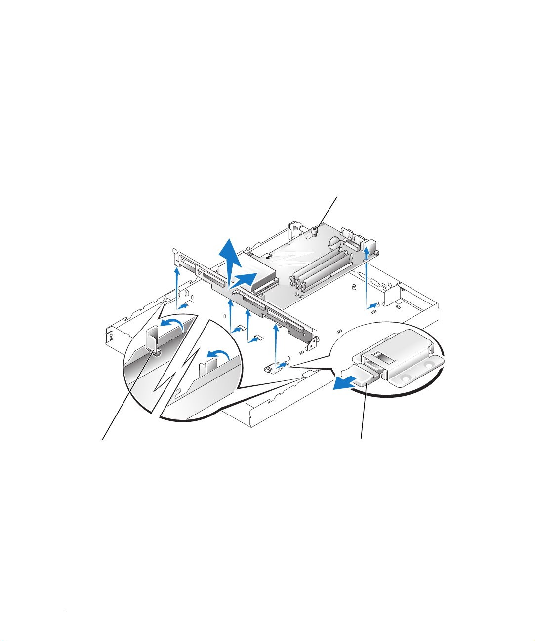
Remove the three Phillip screws that secure the system board to the backplane board. See
Figure 1-2.
4 Replacing the System and Backplane Board Assemblies
backplane securing latch
Page 5
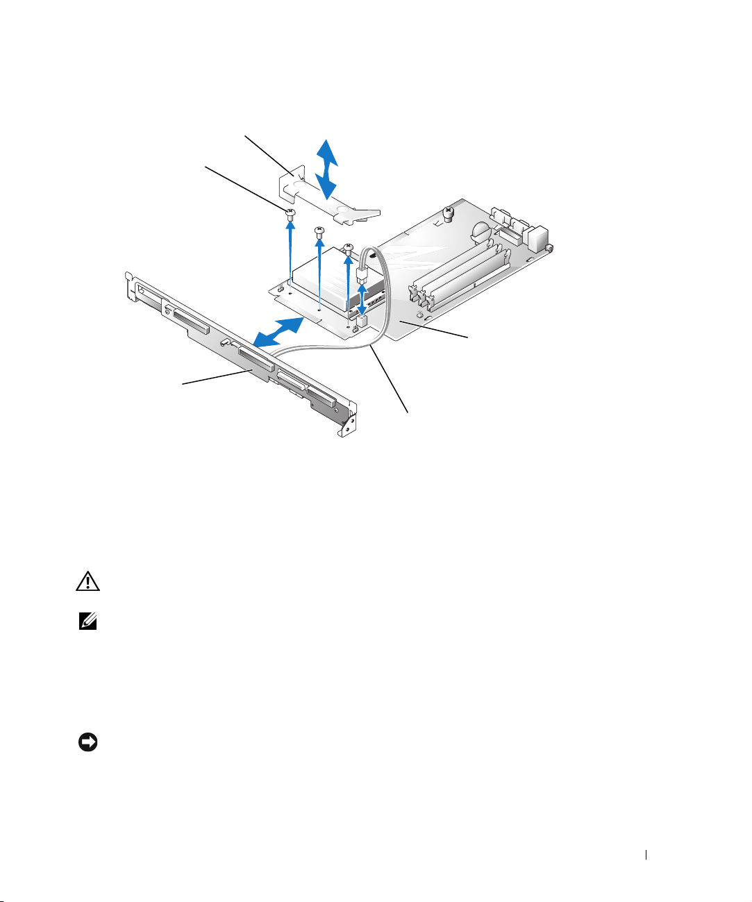
Figure 1-2. Separating the System/Backplane Board Assembly
shroud
screws (3)
system board
backplane board
power cable
22
Remove the power cable from the power connector on the system board. See Figure 1-2.
23
Release the plastic cable tie that secures the cable connector to connector U3 and remove the
free end of the power cable from the backplane board (connector U3).
24
Pull the backplane board away from the system board. See Figure 1-2.
Installing the System/Backplane Board Assembly
CAUTION: See your System Information Guide for complete information about safety precautions,
working inside the computer, and protecting against electrostatic discharge.
NOTE: It is not necessary to remove the hard drives or the CD/diskette drive from the system during this
procedure.
To install the system board/backplane board assembly, perform the following steps:
1
Connect the four-conductor power cable to the back of the backplane (connector U3). Secure
this connector with a plastic cable tie to the backplane.
2
Connect the system board to the backplane board. See Figure 1-2.
NOTICE: Use a screw only in the center screw hole to secure the system board/backplane board to the
chassis.
Using
one
3
secure the system board/backplane board to the chassis
Figure 1-3). Discard the other two screws.
of the three Phillips screws removed in step 21 of the board removal procedure,
using the center screw hole
Replacing the System and Backplane Board Assemblies 5
(see
Page 6

Figure 1-3. Joining the System/Backplane Board Assembly
screw
center screw
hole
www.dell.com | support.dell.com
backplane board
4
Connect the free end of the four-conductor power cable that you installed on the back of the
backplane (in step 1) to the power connector (CN2) on the system board.
5
Lower the system board/backplane board into the system chassis with the grounding posts
through the holes on the system board.
6
Slide the system board/backplane board assembly back towards the system back panel.
Ensure that the tabs on the backplane are installed through their slots on the system chassis,
and that the grounding posts are properly locked in their slotted holes on the system board.
shroud
system board
power cable
7
Secure the backplane securing latch by sliding it toward the backplane until it locks. See
Figure 1-1.
8
Secure the system board to the system chassis by tightening the thumbscrew. See Figure 1-1.
9
Lower the backplane releasing latches to the locked position. See Figure 1-2.
10
Install the riser board. See "Installing the Riser Board" in your
Guide
.
11
Install any expansion cards that were removed. See "Installing an Expansion Card" in your
Installation and Troubleshooting Guide
12
Replace the system battery, if it was removed. See "Replacing the Battery" in your
and Troubleshooting Guide
13
Replace the processor, if it was removed. See "Replacing the Processor" in your
and Troubleshooting Guide
.
.
.
6 Replacing the System and Backplane Board Assemblies
Installation and Troubleshooting
Installation
Installation
Page 7

14
Replace the cooling shrouds.
15
Install the memory modules, if they were removed. See "System Memory" in your
and Troubleshooting Guide
16
Connect the control panel cable to the front of the backplane. See "Installing the Control
Panel Assembly" in your
17
Connect the hard-drive interface cables either to the backplane or through the backplane to
.
Installation and Troubleshooting Guide
.
Installation
the hard-drive controller card, if one is installed.
18
Connect the hard-drives power cables from backplane connectors JP1 and JP2 to the hard
drives. See "Installing a Hard Drive" in your
19
Connect the CD/diskette drive interface cable to the backplane connector CN1.
20
Install the power supply. See "Replacing the Power Supply" in your
Troubleshooting Guide
21
Connect the power supply cable to the back of the backplane (connector J2). See "Replacing
the Power Supply" in your
22
Install the fan assemblies. See "Installing a Fan Assembly " in your
Troubleshooting Guide
23
Close the system. See "Closing the System" in your
24
Reconnect the system to its electrical outlet and turn the system on, including any attached
.
Installation and Troubleshooting Guide
.
Installation and Troubleshooting Guide
Installation and
.
Installation and
Installation and Troubleshooting Guide
peripherals.
.
.
Replacing the System and Backplane Board Assemblies 7
Page 8

www.dell.com | support.dell.com
8 Replacing the System and Backplane Board Assemblies
Page 9

Page 10

Printed in the U.S.A.
0G3929A00
www.dell.com | support.dell.com
Page 11

Page 12

Printed in Malaysia.
0G3929A00
www.dell.com | support.dell.com
Page 13

Page 14

Printed in China.
0G3929A00
www.dell.com | support.dell.com
Page 15

Page 16

Printed in Ireland.
0G3929A00
www.dell.com | support.dell.com
 Loading...