

Page 1

Dell Vostro 3750
Owner's Manual
Regulatory Model P13E
Regulatory Type P13E001
Page 2

Notes, Cautions, and Warnings
NOTE: A NOTE indicates important information that helps you make better use of your
computer.
CAUTION: A CAUTION indicates potential damage to hardware or loss of data if
instructions are not followed.
WARNING: A WARNING indicates a potential for property damage, personal injury, or
death.
Information in this publication is subject to change without notice.
© 2011 Dell Inc. All rights reserved.
Reproduction of these materials in any manner whatsoever without the written permission of Dell Inc. is
strictly forbidden.
Trademarks used in this text:
Latitude™, Latitude ON™, OptiPlex™, Vostro™, and Wi-Fi Catcher™ are trademarks of Dell Inc. Intel®,
Pentium®, Xeon®, Core™, Atom™, Centrino®, and Celeron® are registered trademarks or trademarks of Intel
Corporation in the U.S. and other countries. AMD® is a registered trademark and AMD Opteron™,
AMD Phenom™, AMD Sempron™, AMD Athlon™, ATI Radeon™, and ATI FirePro™ are trademarks of
Advanced Micro Devices, Inc. Microsoft®, Windows®, MS-DOS®, Windows Vista®, the Windows Vista start
button, and Office Outlook
United States and/or other countries.
(BDA) and licensed for use on discs and players. The
owned by the
registered trademark of Wireless Ethernet Compatibility Alliance, Inc.
Other trademarks and trade names may be used in this publication to refer to either the entities claiming the
marks and names or their products, Dell Inc. disclaims any proprietary interest in trademarks and trade
names other than its own.
Bluetooth
Dell™, the DELL logo, Dell Precision™, Precision ON™,ExpressCharge™,
®
are either trademarks or registered trademarks of Microsoft Corporation in the
®
SIG, Inc. and any use of such mark by Dell Inc. is under license.
Blu-ray Disc
™
is a trademark owned by the Blu-ray Disc Association
Bluetooth
®
word mark is a registered trademark and
Wi-Fi
®
is a
2011 – 06
Rev. A00
Page 3

Contents
Notes, Cautions, and Warnings..................................................................2
1 Working on Your Computer......................................................................9
Before Working Inside Your Computer.............................................................................9
Recommended Tools.......................................................................................................11
Turning Off Your Computer..............................................................................................11
After Working Inside Your Computer..............................................................................11
2 Battery........................................................................................................13
Removing The Battery.....................................................................................................13
Installing The Battery......................................................................................................14
3 Secure Digital (SD) Card.........................................................................15
Removing The Secure Digital (SD) Card.........................................................................15
Installing The Secure Digital (SD) Card...........................................................................16
4 ExpressCard..............................................................................................17
Removing The ExpressCard............................................................................................17
Installing The ExpressCard..............................................................................................18
5 Keyboard....................................................................................................19
Removing The Keyboard.................................................................................................19
Installing The Keyboard..................................................................................................26
6 Memory Door............................................................................................27
Removing The Memory Door...........................................................................................27
Installing The Memory Door............................................................................................28
7 Memory......................................................................................................29
Removing The Memory Module......................................................................................29
Page 4

Installing The Memory Module.......................................................................................30
8 Hard Drive..................................................................................................31
Removing The Hard Drive................................................................................................31
Installing The Hard Drive.................................................................................................33
9 Optical Drive..............................................................................................35
Removing The Optical Drive............................................................................................35
Installing The Optical Drive.............................................................................................37
10 Palm Rest.................................................................................................39
Removing The Palmrest..................................................................................................39
Installing The Palmrest....................................................................................................44
11 Hinge Cover.............................................................................................47
Removing The Hinge Cover.............................................................................................47
Installing The Hinge Cover..............................................................................................48
12 Wireless Local Area Network (WLAN) Card.....................................51
Removing the Wireless Local Area Network (WLAN) Card............................................51
Installing The Wireless Local Area Network (WLAN) Card............................................53
13 Display Assembly...................................................................................55
Removing The Display Assembly....................................................................................55
Installing The Display Assembly.....................................................................................58
14 Display Bezel...........................................................................................59
Removing The Display Bezel...........................................................................................59
Installing The Display Bezel............................................................................................60
15 Display Panel..........................................................................................63
Removing The Display Panel...........................................................................................63
Installing The Display Panel............................................................................................66
Page 5

16 Display Cable..........................................................................................69
Removing The Display Cable...........................................................................................69
Installing The Display Cable............................................................................................70
17 Display Brackets and Hinges...............................................................71
Removing The Display Brackets And Hinges..................................................................71
Installing The Display Brackets And Hinges...................................................................73
18 Camera.....................................................................................................75
Removing The Camera Module.......................................................................................75
Installing The Camera Module........................................................................................77
19 Camera Cable..........................................................................................79
Removing The Camera Cable..........................................................................................79
Installing The Camera Cable...........................................................................................80
20 System Fan..............................................................................................83
Removing The System Fan..............................................................................................83
Installing The System Fan...............................................................................................84
21 ExpressCard Cable.................................................................................87
Removing The ExpressCard Cable..................................................................................87
Installing The ExpressCard Cable...................................................................................88
22 ExpressCard Board................................................................................89
Removing The ExpressCard Board..................................................................................89
Installing The ExpressCard Board...................................................................................90
23 LED Board................................................................................................91
Removing The LED Board................................................................................................91
Installing The LED Board.................................................................................................92
24 System Board..........................................................................................93
Removing The System Board..........................................................................................93
Page 6

Installing The System Board...........................................................................................96
25 Heat Sink..................................................................................................99
Removing The Heatsink...................................................................................................99
Installing The Heatsink..................................................................................................100
26 PCH Heatsink........................................................................................103
Removing The PCH Heatsink.........................................................................................103
Installing The PCH Heatsink..........................................................................................104
27 Processor..............................................................................................107
Removing The Processor..............................................................................................107
Installing The Processor...............................................................................................108
28 Coin-Cell Battery..................................................................................111
Removing The Coin-Cell Battery...................................................................................111
Installing The Coin-Cell Battery.....................................................................................112
29 DC-In Port..............................................................................................115
Removing The DC-in Port..............................................................................................115
Installing The DC-in Port...............................................................................................116
30 Input/Output Board..............................................................................119
Removing The Input/Output (I/O) Panel.........................................................................119
Installing The Input/Output (I/O) Panel..........................................................................120
31 Sub-Woofer...........................................................................................123
Removing The SubWoofer............................................................................................123
Installing The SubWoofer..............................................................................................124
32 Speaker..................................................................................................125
Removing The Speakers................................................................................................125
Installing The Speakers.................................................................................................127
Page 7

33 System Setup........................................................................................129
System Setup Overview................................................................................................129
System Setup Enter.......................................................................................................129
System Setup Screens..................................................................................................130
System Setup Options...................................................................................................131
34 Diagnostics............................................................................................135
Device Status Lights......................................................................................................135
Battery Status Lights.....................................................................................................135
Diagnostic Beep Codes.................................................................................................135
35 Specifications.......................................................................................137
36 Contacting Dell.....................................................................................147
Contacting Dell..............................................................................................................147
Page 8

8
Page 9

1
Working on Your Computer
Before Working Inside Your Computer
Use the following safety guidelines to help protect your computer from potential
damage and to help to ensure your personal safety. Unless otherwise noted,
each procedure included in this document assumes that the following
conditions exist:
• You have performed the steps in Working on Your Computer.
• You have read the safety information that shipped with your computer.
• A component can be replaced or--if purchased separately--installed by
performing the removal procedure in reverse order.
WARNING: Before working inside your computer, read the safety information that
shipped with your computer. For additional safety best practices information, see
the Regulatory Compliance Homepage at www.dell.com/regulatory_compliance.
CAUTION: Many repairs may only be done by a certified service technician. You
should only perform troubleshooting and simple repairs as authorized in your
product documentation, or as directed by the online or telephone service and
support team. Damage due to servicing that is not authorized by Dell is not covered
by your warranty. Read and follow the safety instructions that came with the
product.
CAUTION: To avoid electrostatic discharge, ground yourself by using a wrist
grounding strap or by periodically touching an unpainted metal surface, such as a
connector on the back of the computer.
CAUTION: Handle components and cards with care. Do not touch the components
or contacts on a card. Hold a card by its edges or by its metal mounting bracket.
Hold a component such as a processor by its edges, not by its pins.
9
Page 10

CAUTION: When you disconnect a cable, pull on its connector or on its pull-tab, not
on the cable itself. Some cables have connectors with locking tabs; if you are
disconnecting this type of cable, press in on the locking tabs before you disconnect
the cable. As you pull connectors apart, keep them evenly aligned to avoid bending
any connector pins. Also, before you connect a cable, ensure that both connectors
are correctly oriented and aligned.
NOTE: The color of your computer and certain components may appear differently
than shown in this document.
To avoid damaging your computer, perform the following steps before you begin
working inside the computer.
1. Ensure that your work surface is flat and clean to prevent the computer
cover from being scratched.
2. Turn off your computer (see
Turning Off Your Computer
).
3. If the computer is connected to a docking device (docked) such as the
optional Media Base or Battery Slice, undock it.
CAUTION: To disconnect a network cable, first unplug the cable from your
computer and then unplug the cable from the network device.
4. Disconnect all network cables from the computer.
5. Disconnect your computer and all attached devices from their electrical
outlets.
6. Close the display and turn the computer upside-down on a flat work
surface.
NOTE: To avoid damaging the system board, you must remove the main battery
before you service the computer.
7. Remove the main battery.
8. Turn the computer top-side up.
9. Open the display.
10. Press the power button to ground the system board.
CAUTION: To guard against electrical shock, always unplug your computer from the
electrical outlet before opening the display.
CAUTION: Before touching anything inside your computer, ground yourself by
touching an unpainted metal surface, such as the metal at the back of the
computer. While you work, periodically touch an unpainted metal surface to
dissipate static electricity, which could harm internal components.
10
Page 11
11. Remove any installed ExpressCards or Smart Cards from the appropriate
slots.
Recommended Tools
The procedures in this document may require the following tools:
• Small flat-blade screwdriver
• #0 Phillips screwdriver
• #1 Phillips screwdriver
• Small plastic scribe
• Flash BIOS update program CD
Turning Off Your Computer
CAUTION: To avoid losing data, save and close all open files and exit all open
programs before you turn off your computer.
1. Shut down the operating system:
• In Windows Vista :
Click Start
Start menu as shown below, and then click Shut Down.
• In Windows XP:
Click Start → Turn Off Computer → Turn Off . The computer turns off
after the operating system shutdown process is complete.
2. Ensure that the computer and all attached devices are turned off. If your
computer and attached devices did not automatically turn off when you
shut down your operating system, press and hold the power button for
about 4 seconds to turn them off.
, then click the arrow in the lower-right corner of the
After Working Inside Your Computer
After you complete any replacement procedure, ensure you connect any
external devices, cards, and cables before turning on your computer.
11
Page 12

CAUTION: To avoid damage to the computer, use only the battery designed for this
particular Dell computer. Do not use batteries designed for other Dell computers.
1. Connect any external devices, such as a port replicator, battery slice, or
media base, and replace any cards, such as an ExpressCard.
2. Connect any telephone or network cables to your computer.
CAUTION: To connect a network cable, first plug the cable into the network device
and then plug it into the computer.
3. Replace the battery.
4. Connect your computer and all attached devices to their electrical outlets.
5. Turn on your computer.
12
Page 13
Battery
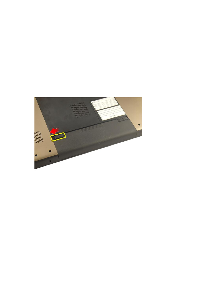
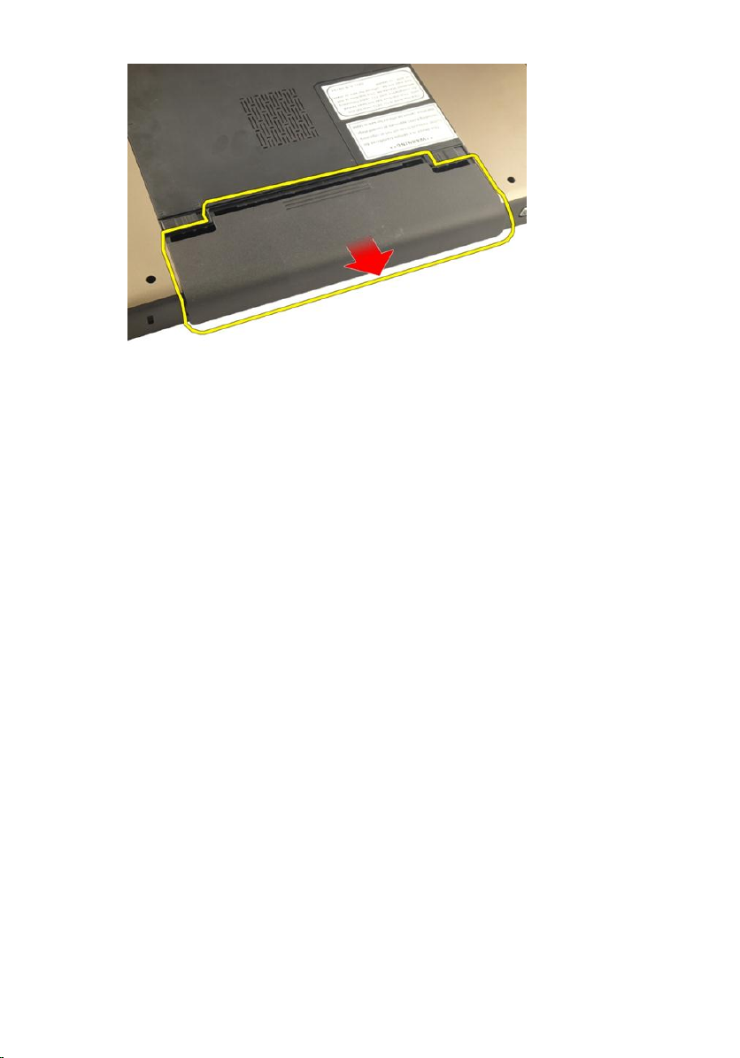
Removing The Battery
2
1. Follow the procedures in
2. Slide the release latches to unlock the battery.
3. Slide the battery out of the chassis and remove it from the computer.
Before Working On Your Computer
.
13
Page 14
Installing The Battery
1. Slide the battery into its slot until it clicks into place.
2. Follow the procedures in
After Working Inside Your Computer
.
14
Page 15
Secure Digital (SD) Card
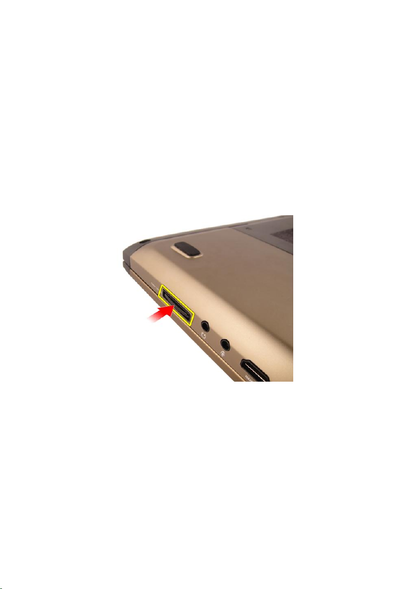
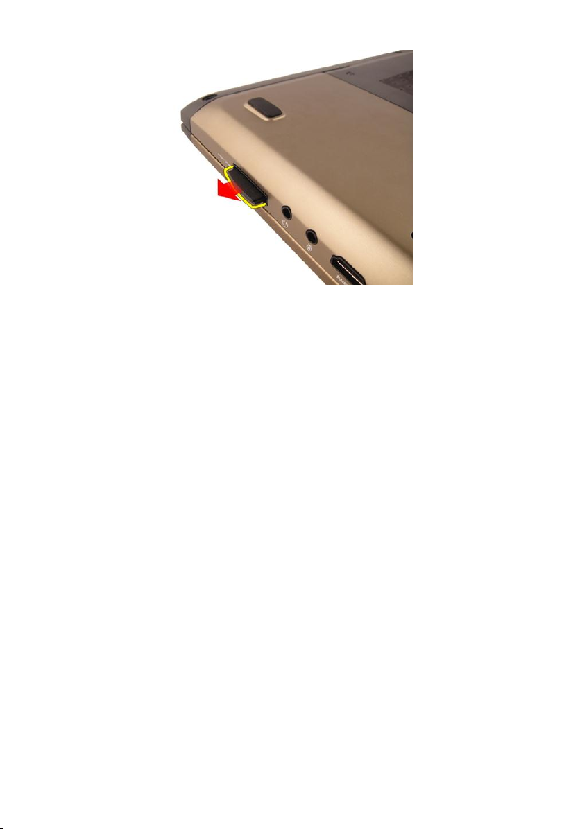
Removing The Secure Digital (SD) Card
3
1. Follow the procedures in
2. Remove the
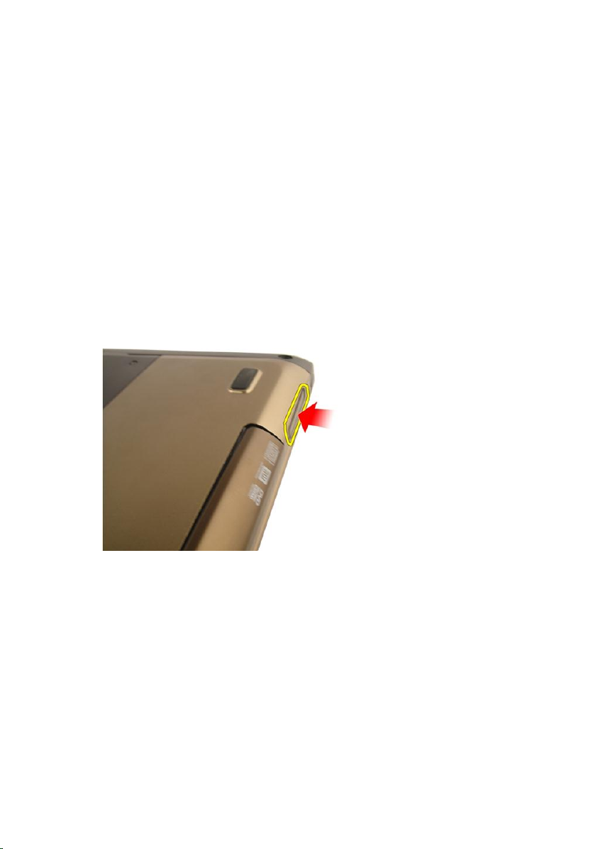
3. Press in on the SD card to release it from the computer.
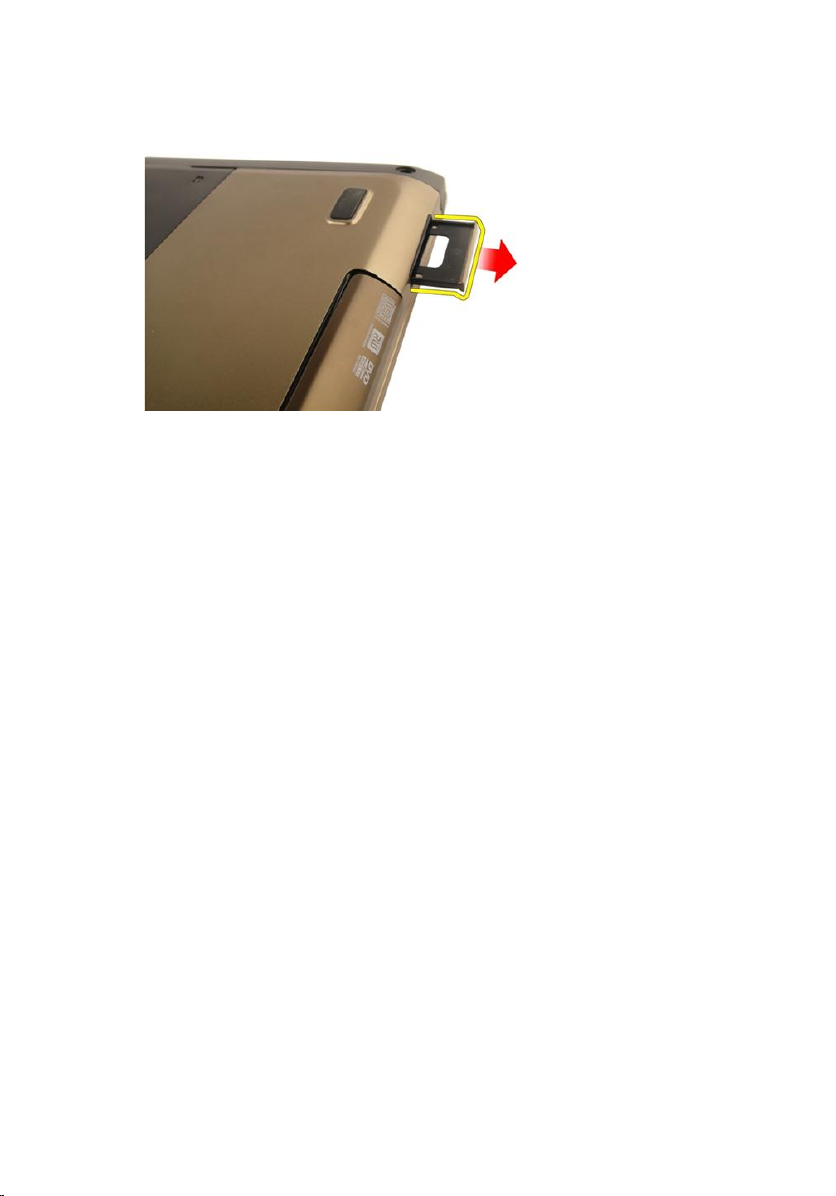
4. Remove the SD card from the computer.
battery
Before Working On Your Computer
.
.
15
Page 16
Installing The Secure Digital (SD) Card
1. Push the SD card into the slot until it clicks into place.
2. Install the
3. Follow the procedures in
battery
.
After Working Inside Your Computer
.
16
Page 17
ExpressCard
Removing The ExpressCard
4
1. Follow the procedures in
2. Remove the
3. Press the Express dummy card and the dummy card will pop out.
4. Take the Express dummy card out of the system.
battery
Before Working On Your Computer
.
.
17
Page 18
Installing The ExpressCard
1. Slide the ExpressCard into its slot until it clicks into place.
2. Install the
3. Follow the procedures in
battery
.
After Working Inside Your Computer
.
18
Page 19

Keyboard
Removing The Keyboard
5
1. Follow the procedures in
2. Remove the
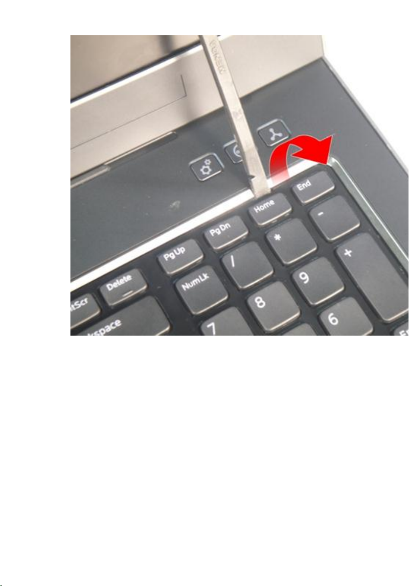
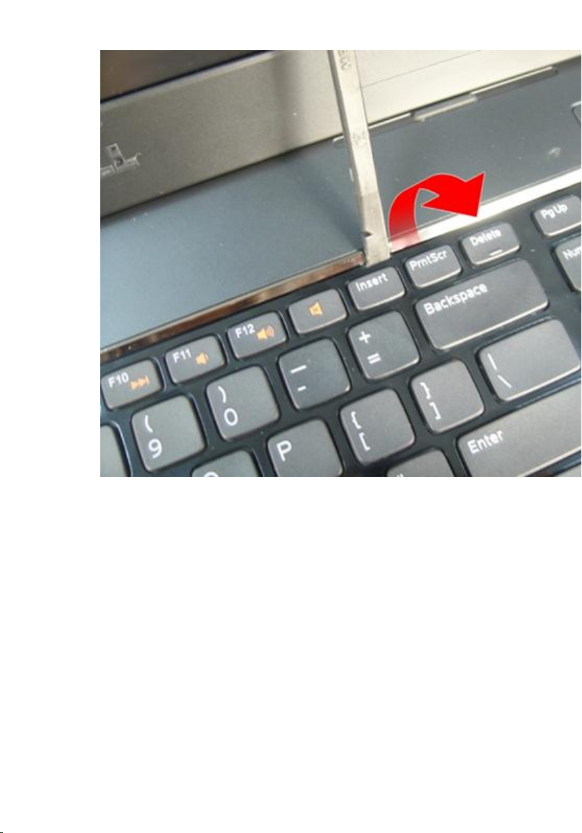
3. Press the keyboard down. Pry the keyboard with the use of a flat-head
screwdriver towards the display to reveal the first keyboard retainer.
battery
Before Working On Your Computer
.
.
19
Page 20
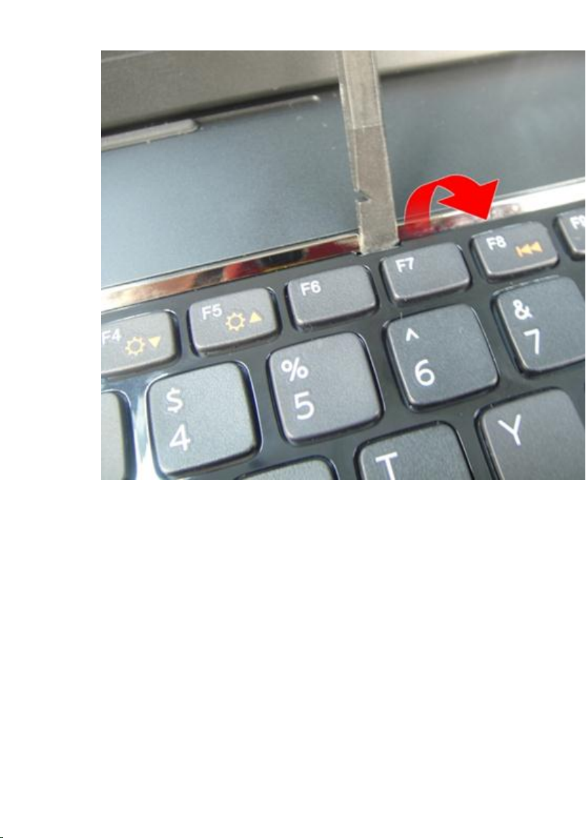
4. Pry up the second keyboard retainer.
20
Page 21
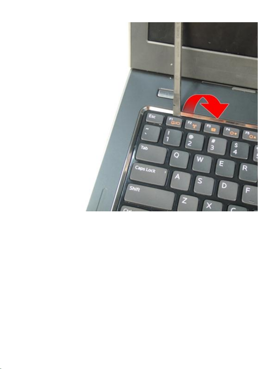
5. Pry up the third keyboard retainer.
21
Page 22
6. Pry up the fourth keyboard retainer.
22
Page 23
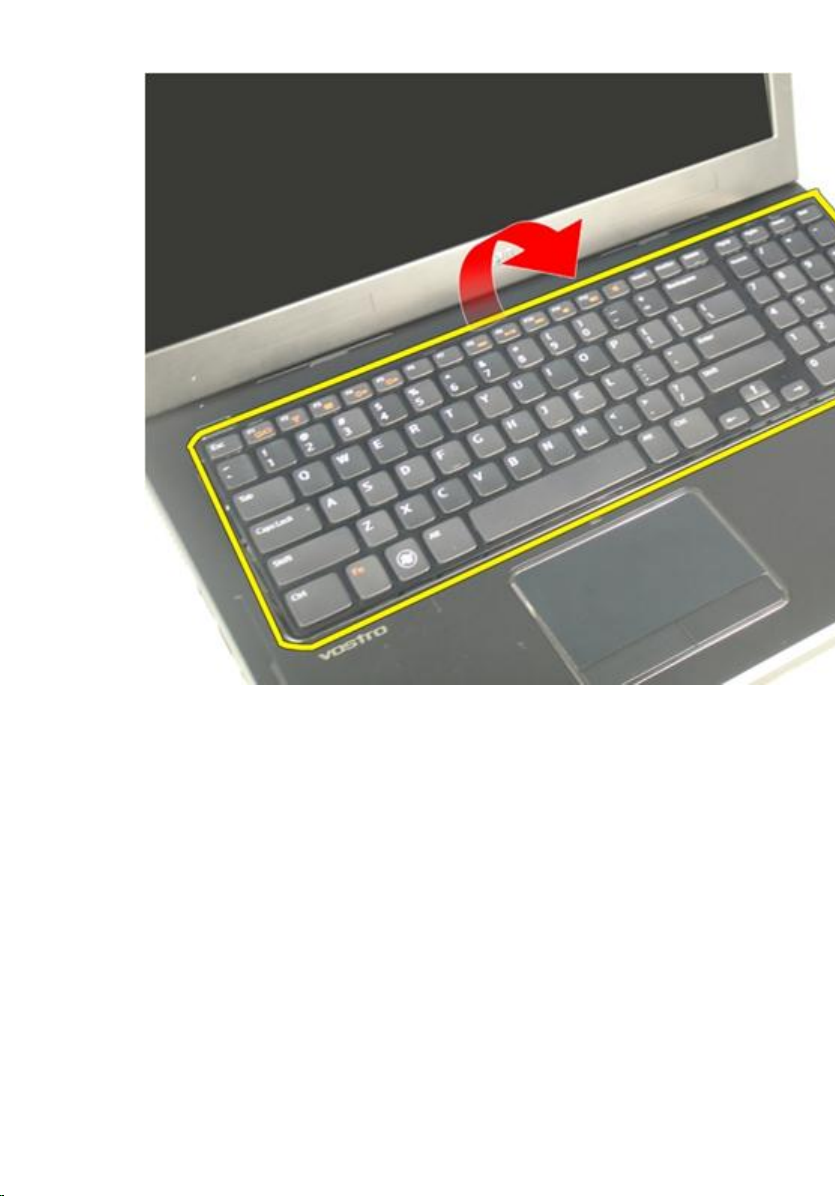
7. Pull up the keyboard from the palm rest.
23
Page 24
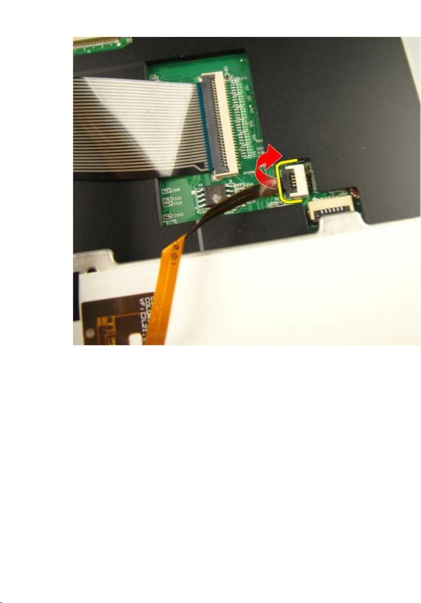
8. Release the latch on the system board connector then disconnect the
keyboard back-light cable.
24
Page 25
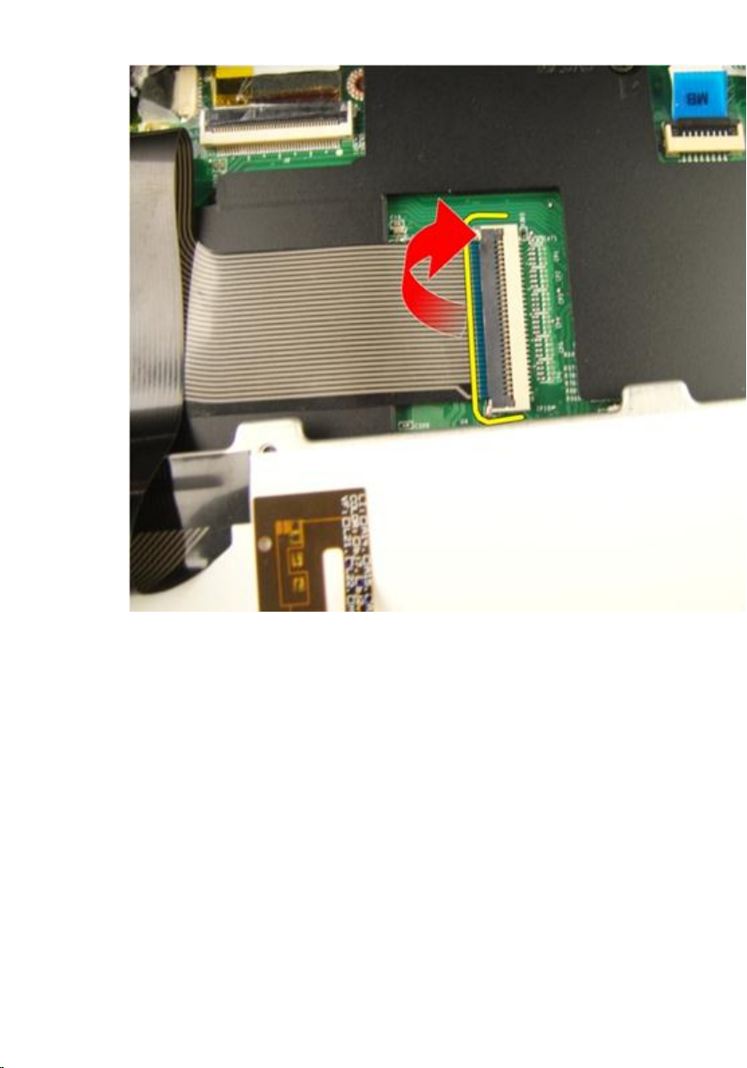
9. Release the latch on the system board connector and then disconnect the
keyboard cable.
25
Page 26
Installing The Keyboard
1. Connect the keyboard data cable to the back of the keyboard.
2. If your computer comes with a backlit keyboard, connect the keyboard
backlight cable.
3. Replace the adhesive tape to secure the keyboard data cable to the back of
the keyboard.
4. Install the keyboard.
5. Install the
6. Follow the procedures in
26
battery
.
After Working Inside Your Computer
.
Page 27
Memory Door
Removing The Memory Door
6
1. Follow the procedures in
2. Remove the
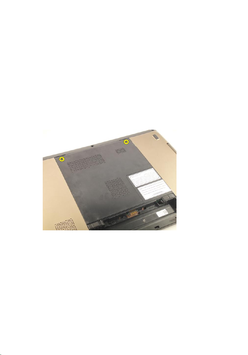
3. Loosen the screws that secure the memory door.
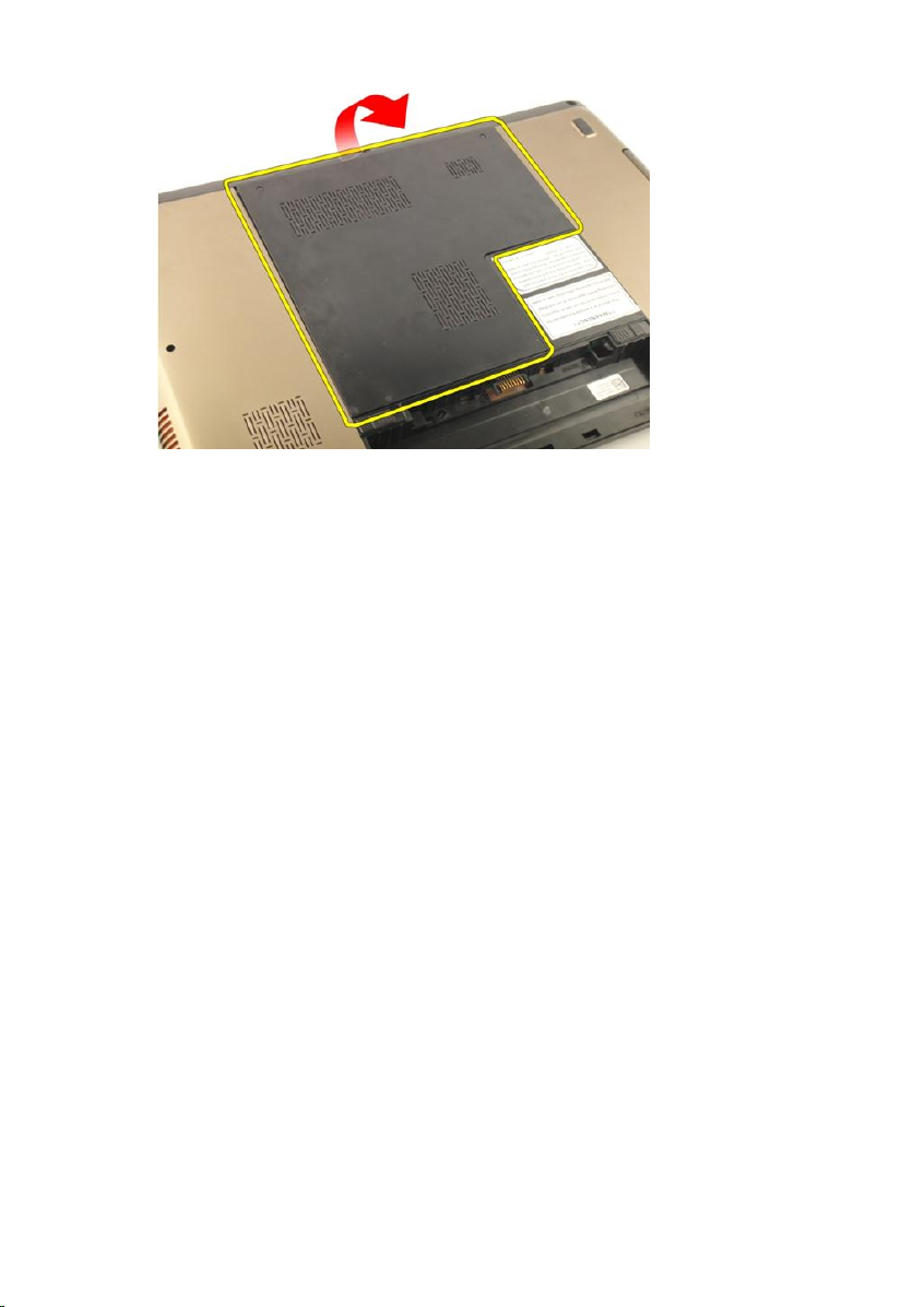
4. Pry up the memory door near the screw hole, lift, and remove it.
battery
Before Working On Your Computer
.
.
27
Page 28
Installing The Memory Door
1. Install the memory door on the back of the computer.
2. Install the screws securing the memory door.
3. Install the
4. Follow the procedures in
battery
.
After Working Inside Your Computer
.
28
Page 29
Memory
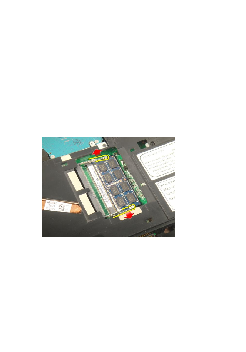
Removing The Memory Module
7
1. Follow the procedures in
2. Remove the
3. Remove the
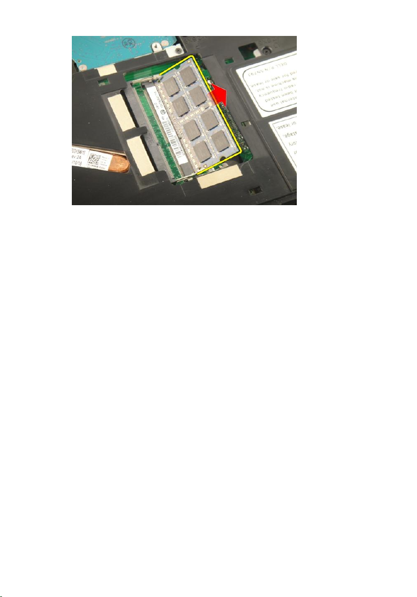
4. Pry the retention clips away from the memory module until it pops up.
5. Remove the memory module from its connector on the system board.
battery
memory door
Before Working On Your Computer
.
.
.
29
Page 30
Installing The Memory Module
1. Insert the memory module into the memory socket.
2. Press down on the memory module until the retention clips secure the
memory module in place.
3. Install the
4. Install the
5. Follow the procedures in
memory door
battery
.
.
After Working Inside Your Computer
.
30
Page 31

Hard Drive
Removing The Hard Drive
8
1. Follow the procedures in
2. Remove the
3. Remove the
4. Remove the screws that secure the hard-drive bracket.
5. Slide the hard drive module in the direction shown in the image below.
battery
memory door
Before Working On Your Computer
.
.
.
31
Page 32

6. Remove the hard drive module from the system board.
7. Remove the screws that secure the hard-drive bracket.
32
Page 33
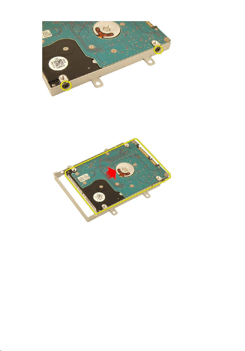
8. Slide the hard drive from the hard-drive bracket.
Installing The Hard Drive
1. Tighten the screws to secure the hard-drive bracket assembly.
2. Install the
3. Install the
4. Follow the procedures in
memory door
battery
.
.
After Working Inside Your Computer
.
33
Page 34

34
Page 35

Optical Drive
Removing The Optical Drive
9
1. Follow the procedures in
2. Remove the
3. Remove the
4. Remove the screw that secures the optical-drive bracket.
5. Pull out the optical drive module from the computer.
battery
memory door
Before Working On Your Computer
.
.
.
35
Page 36

6. Remove the screws that secure the optical-drive bracket.
7. Remove the optical-drive bracket from the optical drive module.
36
Page 37

8. Slide the optical-drive bracket off the optical drive module.
Installing The Optical Drive
1. Tighten the screws to secure the bracket to the back of the optical drive.
2. Slide the optical drive into the compartment on the right side of the chassis.
3. Tighten the screw to secure the optical drive to the computer.
4. Install the
5. Install the
6. Follow the procedures in
memory door
battery
.
.
After Working Inside Your Computer
.
37
Page 38

38
Page 39

Palm Rest
Removing The Palmrest
10
1. Follow the procedures in
2. Remove the
3. Remove the
4. Remove the
5. Remove the
6. Remove the rubbers from the bottom base.
battery
keyboard
memory door
optical drive
Before Working On Your Computer
.
.
.
.
.
39
Page 40

7. Remove the screws that secure the bottom base.
8. Flip the computer around and remove the screws that secure the palm rest.
40
Page 41

9. Release the latch on the system board connector and then disconnect the
power-button cable.
10. Release the latch on the system board connector and then disconnect the
touch pad cable.
41
Page 42

11. Release the latch on the system board connector and then disconnect the
fingerprint-reader cable.
12. Release the latch on the system board connector and then disconnect the
hot-key cable.
42
Page 43

13. Pry up the right side of the palm rest.
14. Pry up the left side of the palm rest.
43
Page 44
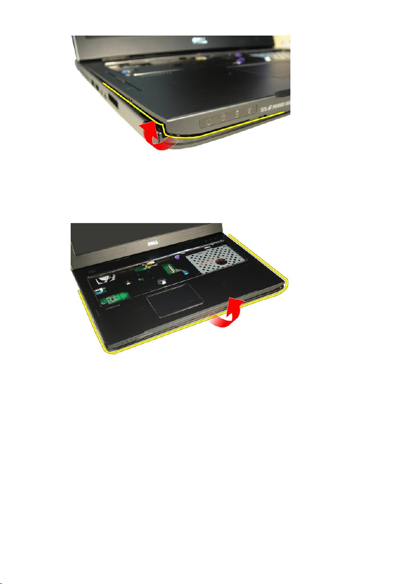
15. Pry up the sides of the palm rest and remove it.
Installing The Palmrest
1. Connect all cables to the palm rest.
2. Tighten the captive screws to secure the palm rest in place.
3. Tighten the screws on the bottom of the system that secure the palm rest.
4. Install the
5. Install the
6. Install the
44
optical drive
memory door
keyboard
.
.
.
Page 45

7. Install the
8. Follow the procedures in
battery
.
After Working Inside Your Computer
.
45
Page 46

46
Page 47
Hinge Cover
Removing The Hinge Cover
11
1. Follow the procedures in
2. Remove the
3. Remove the
4. Remove the
5. Remove the
6. Remove the
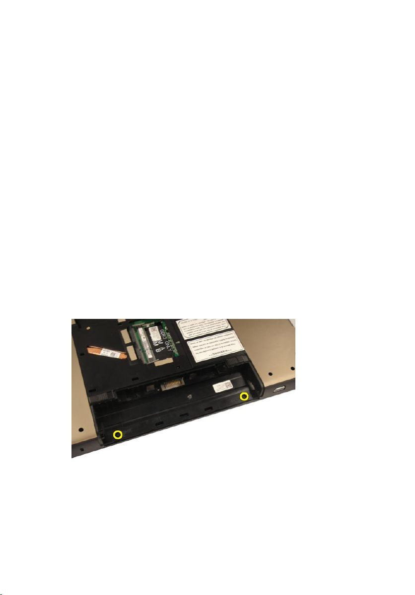
7. Remove the screws that secure the hinge cover from the battery
compartment.
battery
keyboard
optical drive
memory door
palm rest
Before Working On Your Computer
.
.
.
.
.
.
8. Press and hold the three hooks to disengage.
47
Page 48

9. Flip the computer around and remove the hinge cover.
Installing The Hinge Cover
1. Tighten the screws to secure the display hinges in place.
2. Install the
3. Install the
4. Install the
5. Install the
6. Install the
48
palm rest
.
memory door
optical drive
keyboard
battery
.
.
.
.
Page 49

7. Follow the procedures in
After Working Inside Your Computer
.
49
Page 50

50
Page 51

Wireless Local Area Network (WLAN) Card
Removing the Wireless Local Area Network (WLAN) Card
12
1. Follow the procedures in
2. Remove the
3. Remove the
4. Remove the
5. Remove the
6. Remove the
7. Disconnect the antenna cable from the WLAN card.
battery
keyboard
memory door
optical drive
palm rest
Before Working On Your Computer
.
.
.
.
.
.
8. Disconnect the antenna cable from the WLAN card.
51
Page 52

9. Remove the screw that secures the WLAN card.
10. Pull the WLAN card straight out of its socket and remove it.
52
Page 53

Installing The Wireless Local Area Network (WLAN) Card
1. Slide the WLAN card into its slot.
2. Tighten the screw that secures the WLAN card in place.
3. Connect the antenna cables according to the color code on the WLAN
card.
4. Install the
5. Install the
6. Install the
7. Install the
8. Install the
9. Follow the procedures in
palm rest
optical drive
memory door
keyboard
battery
.
.
.
.
.
After Working Inside Your Computer
.
53
Page 54

54
Page 55

Display Assembly
Removing The Display Assembly
13
1. Follow the procedures in
2. Remove the
3. Remove the
4. Remove the
5. Remove the
6. Remove the
7. Remove the
8. Remove the
9. Remove the screws that secure the display hinge.
battery
keyboard
memory door
optical drive
palm rest
hinge cover
WLAN card
Before Working On Your Computer
.
.
.
.
.
.
.
.
10. Release the latch on the system board and then disconnect the display
cable.
55
Page 56

11. Disconnect the camera cable from the system board.
12. Remove the screws that secure the left hinge.
56
Page 57

13. Remove the screws that secure the right hinge.
14. Lift up the display assembly and remove it from the computer.
57
Page 58

Installing The Display Assembly
1. Attach the display assembly to the computer.
2. Tighten the screws on the display assembly to secure it in place.
3. Tighten the screws on the bottom of the system to secure the display
assembly in place.
4. Install the
5. Install the
6. Install the
7. Install the
8. Install the
9. Install the
10. Install the
11. Follow the procedures in
WLAN card
hinge cover
palm rest
.
.
.
optical drive
memory door
keyboard
battery
.
.
.
.
After Working Inside Your Computer
.
58
Page 59

Display Bezel
Removing The Display Bezel
14
1. Follow the procedures in
2. Remove the
3. Remove the
4. Remove the
5. Remove the
6. Remove the
7. Remove the
8. Remove the
9. Remove the
10. Pry up the upper side of the bezel.
battery
keyboard
memory door
optical drive
palm rest
hinge cover
WLAN card
display assembly
Before Working On Your Computer
.
.
.
.
.
.
.
.
.
11. Pry up the sides of the bezel.
59
Page 60

12. Remove the display bezel from display hinge .
Installing The Display Bezel
1. Attach the display bezel to the display hinge.
2. Install the
3. Install the
4. Install the
5. Install the
6. Install the
60
display assembly
WLAN card
hinge cover
palm rest
optical drive
.
.
.
.
.
Page 61

7. Install the
8. Install the
9. Install the
10. Follow the procedures in
memory door
keyboard
battery
.
.
.
After Working Inside Your Computer
.
61
Page 62

62
Page 63

Display Panel
Removing The Display Panel
15
1. Follow the procedures in
2. Remove the
3. Remove the
4. Remove the
5. Remove the
6. Remove the
7. Remove the
8. Remove the
9. Remove the
10. Remove the
11. Remove the screw that secures the left-display bracket.
battery
keyboard
memory door
optical drive
palm rest
hinge cover
WLAN card
display assembly
display bezel
Before Working On Your Computer
.
.
.
.
.
.
.
.
.
.
12. Remove the screws that secure the left-display bracket.
63
Page 64

13. Remove the screw that secures the right-display bracket.
14. Remove the screws that secure the right-display bracket.
64
Page 65

15. Release the display cable from the trough as shown in the image.
16. Release the WLAN antenna cable from the trough as shown in the image
below.
65
Page 66

17. Lift and remove the display panel module from the display cover.
Installing The Display Panel
1. Connect the WLAN antenna cable though the trough.
2. Align the display bracket with the display panel and tighten the screws
securing the display bracket in place.
3. Install the
4. Install the
5. Install the
6. Install the
display bezel
.
display assembly
WLAN card
hinge cover
.
.
.
66
Page 67

7. Install the
8. Install the
9. Install the
10. Install the
11. Install the
12. Follow the procedures in
palm rest
.
optical drive
memory door
keyboard
battery
.
.
.
.
After Working Inside Your Computer
.
67
Page 68

68
Page 69
Display Cable
Removing The Display Cable
16
1. Follow the procedures in
2. Remove the
3. Remove the
4. Remove the
5. Remove the
6. Remove the
7. Remove the
8. Remove the
9. Remove the
10. Remove the
11. Remove the
12. Peel off the tape from the display cable.
battery
keyboard
memory door
optical drive
palm rest
hinge cover
WLAN card
display assembly
display bezel
display panel
Before Working On Your Computer
.
.
.
.
.
.
.
.
.
.
.
69
Page 70

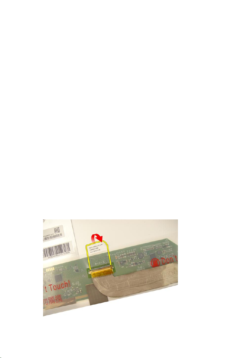
13. Disconnect the display cable from the display panel.
Installing The Display Cable
1. Connect the display cable to the display panel.
2. Affix the tape to the display cable.
3. Install the
4. Install the
5. Install the
6. Install the
7. Install the
8. Install the
9. Install the
10. Install the
11. Install the
12. Install the
13. Follow the procedures in
70
display panel
display bezel
display assembly
WLAN card
hinge cover
palm rest
optical drive
.
.
.
.
memory door
keyboard
battery
.
.
.
.
.
.
After Working Inside Your Computer
.
Page 71

Display Brackets and Hinges
Removing The Display Brackets And Hinges
17
1. Follow the procedures in
2. Remove the
3. Remove the
4. Remove the
5. Remove the
6. Remove the
7. Remove the
8. Remove the
9. Remove the
10. Remove the
11. Remove the
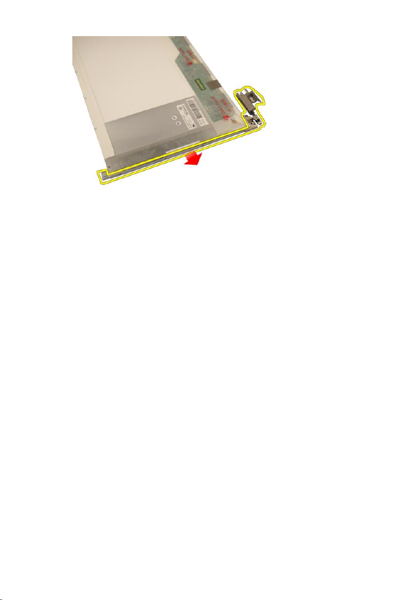
12. Remove the screws that secure the left-display bracket.
battery
keyboard
memory door
optical drive
palm rest
hinge cover
WLAN card
display assembly
display bezel
display panel
Before Working On Your Computer
.
.
.
.
.
.
.
.
.
.
.
71
Page 72

13. Remove the left-display bracket.
14. Remove the screws that secure the right-display bracket.
15. Remove the right-display bracket.
72
Page 73
Installing The Display Brackets And Hinges
1. Replace the screws to secure the left and the right display brackets.
2. Install the
3. Install the
4. Install the
5. Install the
6. Install the
7. Install the
8. Install the
9. Install the
10. Install the
11. Install the
12. Follow the procedures in
display panel
display bezel
.
.
display assembly
WLAN card
hinge cover
palm rest
optical drive
memory door
keyboard
battery
.
.
.
.
.
.
.
After Working Inside Your Computer
.
.
73
Page 74

74
Page 75

Camera
Removing The Camera Module
18
1. Follow the procedures in
2. Remove the
3. Remove the
4. Remove the
5. Remove the
6. Remove the
7. Remove the
8. Remove the
9. Remove the
10. Remove the
11. Remove the
12. Remove the
13. Remove the
14. Lift the camera module off the display cover.
battery
media dummy card
ExpressCard
keyboard
memory door
optical drive
palm rest
hinge cover
WLAN card
display assembly
display bezel
display panel
Before Working On Your Computer
.
.
.
.
.
.
.
.
.
.
.
.
.
75
Page 76

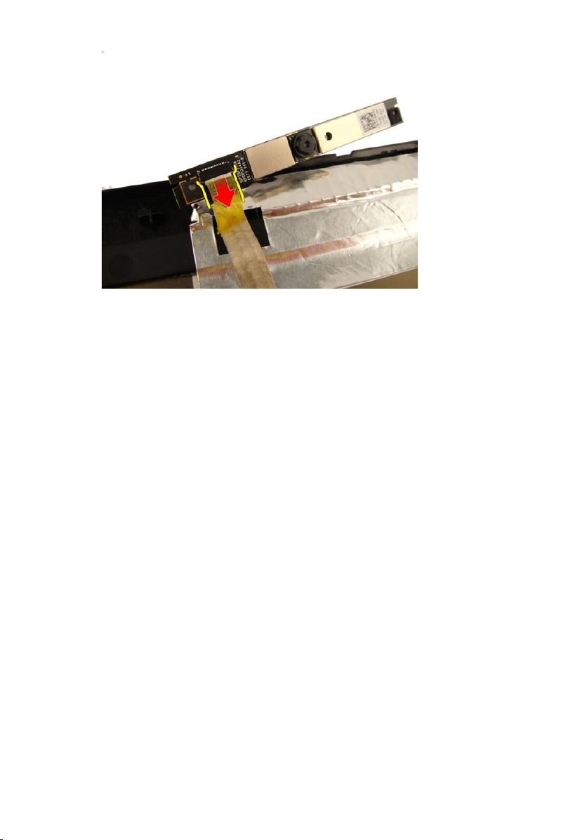
15. Remove the tape from the camera module.
16. Disconnect the camera cable and remove the camera module.
76
Page 77
Installing The Camera Module
1. Connect the camera cable and the camera module.
2. Affix the tape to the camera module.
3. Install the
4. Install the
5. Install the
6. Install the
7. Install the
8. Install the
9. Install the
10. Install the
11. Install the
12. Install the
13. Install the
14. Install the
15. Follow the procedures in
display panel
display bezel
display assembly
WLAN card
hinge cover
palm rest
optical drive
.
.
.
.
memory door
keyboard
ExpressCard
.
.
media dummy card
battery
.
.
.
.
.
.
After Working Inside Your Computer
.
77
Page 78

78
Page 79

Camera Cable
Removing The Camera Cable
19
1. Follow the procedures in
2. Remove the
3. Remove the
4. Remove the
5. Remove the
6. Remove the
7. Remove the
8. Remove the
9. Remove the
10. Remove the
11. Remove the
12. Remove the
13. Remove the
14. Remove the
15. Remove the tape securing the camera cable.
battery
media dummy card
ExpressCard
keyboard
memory door
optical drive
palm rest
hinge cover
WLAN card
display assembly
display bezel
display panel
camera module
Before Working On Your Computer
.
.
.
.
.
.
.
.
.
.
.
.
.
.
79
Page 80

16. Remove the camera cable off the display cover.
Installing The Camera Cable
1. Install the camera cable.
2. Attach the tape that secures the camera cable.
3. Install the
4. Install the
5. Install the
6. Install the
80
camera module
display panel
display bezel
.
.
.
display assembly
.
Page 81

7. Install the
8. Install the
9. Install the
10. Install the
11. Install the
12. Install the
13. Install the
14. Install the
15. Install the
16. Follow the procedures in
WLAN card
hinge cover
palm rest
optical drive
.
.
.
.
memory door
keyboard
ExpressCard
.
.
media dummy card
battery
.
.
.
After Working Inside Your Computer
.
81
Page 82

82
Page 83

System Fan
Removing The System Fan
20
1. Follow the procedures in
2. Remove the
3. Remove the
4. Remove the
5. Remove the
6. Remove the
7. Disconnect the fan cable from the system board.
8. Remove the screws that secure the system fan module.
battery
keyboard
memory door
optical drive
palm rest
Before Working On Your Computer
.
.
.
.
.
.
83
Page 84

9. Remove the system fan from the bottom base module.
Installing The System Fan
1. Tighten the screws that secure the system fan module to the base of the
computer.
2. Connect the system fan cable to the system board.
3. Install the
4. Install the
5. Install the
6. Install the
palm rest
.
optical drive
memory door
keyboard
.
.
.
84
Page 85

7. Install the
8. Follow the procedures in
battery
.
After Working Inside Your Computer
.
85
Page 86

86
Page 87

ExpressCard Cable
Removing The ExpressCard Cable
21
1. Follow the procedures in
2. Remove the
3. Remove the
4. Remove the
5. Remove the
6. Remove the
7. Release the latch on the system board connector and then disconnect the
ExpressCard board cable.
battery
keyboard
memory door
optical drive
palm rest
Before Working On Your Computer
.
.
.
.
.
.
8. Release the latch on the ExpressCard board connector and then disconnect
the ExpressCard cable.
87
Page 88

Installing The ExpressCard Cable
1. Tighten the latch on the ExpressCard board connector and then connect
the ExpressCard cable.
2. Tighten the latch on the system board connector and then connect the
ExpressCard board cable.
3. Install the
4. Install the
5. Install the
6. Install the
7. Install the
8. Follow the procedures in
palm rest
.
optical drive
memory door
keyboard
battery
.
.
.
.
After Working Inside Your Computer
.
88
Page 89

ExpressCard Board
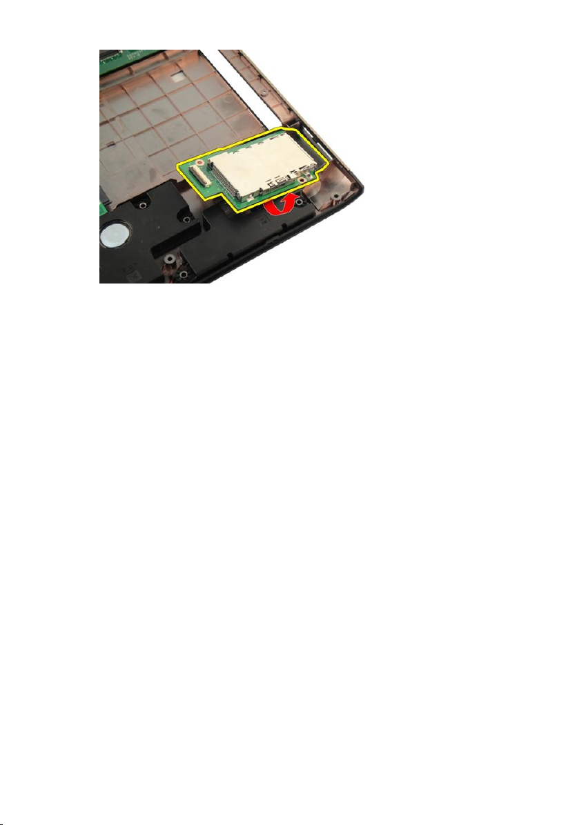
Removing The ExpressCard Board
22
1. Follow the procedures in
2. Remove the
3. Remove the
4. Remove the
5. Remove the
6. Remove the
7. Remove the
8. Remove the screws that secure the ExpressCard board.
battery
keyboard
memory door
optical drive
palm rest
ExpressCard cable
Before Working On Your Computer
.
.
.
.
.
.
.
9. Remove the ExpressCard board.
89
Page 90
Installing The ExpressCard Board
1. Install the screws securing the ExpressCard board to the computer.
2. Install the
3. Install the
4. Install the
5. Install the
6. Install the
7. Install the
8. Follow the procedures in
ExpressCard cable
palm rest
optical drive
memory door
keyboard
battery
.
.
.
.
.
After Working Inside Your Computer
.
.
90
Page 91

LED Board
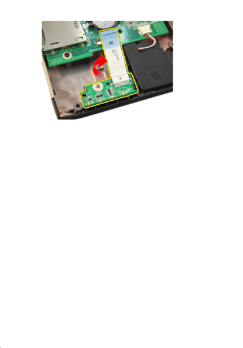
Removing The LED Board
23
1. Follow the procedures in
2. Remove the
3. Remove the
4. Remove the
5. Remove the
6. Remove the
7. Release the latch on system board connector and then disconnect the LED
cable.
battery
keyboard
memory door
optical drive
palm rest
Before Working On Your Computer
.
.
.
.
.
.
8. Remove the LED board from the chassis.
91
Page 92
Installing The LED Board
1. Align the LED board to the chassis.
2. Connect the LED cable to the system board connector.
3. Install the
4. Install the
5. Install the
6. Install the
7. Install the
8. Follow the procedures in
palm rest
.
optical drive
memory door
keyboard
battery
.
.
.
.
After Working Inside Your Computer
.
92
Page 93

System Board
Removing The System Board
24
1. Follow the procedures in
2. Remove the
3. Remove the
4. Remove the
5. Remove the
6. Remove the
7. Remove the
8. Remove the
9. Remove the
10. Remove the
11. Remove the
12. Remove the
13. Remove the
14. Disconnect the DC-in cable from the system board.
battery
media dummy card
ExpressCard
keyboard
memory door
optical drive
palm rest
hinge cover
WLAN card
display assembly
system fan
ExpressCard cable
Before Working On Your Computer
.
.
.
.
.
.
.
.
.
.
.
.
93
Page 94

15. Disconnect the speaker cable from the system board.
16. Disconnect the sub-woofer cable from the system board.
94
Page 95

17. Remove the screws that secure the system board.
18. Disconnect the system board connector from the Input/Output (I/O) panel.
95
Page 96

19. Lift and remove the system board from the chassis.
Installing The System Board
1. Install all the cables to the system board.
2. Install the screws securing the system board to the base of the computer.
3. Replace the speaker cable and the sub-woofer cables.
4. Install the
5. Install the
6. Install the
96
ExpressCard cable
system fan
display assembly
.
.
.
Page 97

7. Install the
8. Install the
9. Install the
10. Install the
11. Install the
12. Install the
13. Install the
14. Install the
15. Install the
16. Follow the procedures in
WLAN card
hinge cover
palm rest
optical drive
.
.
.
.
memory door
keyboard
ExpressCard
.
.
media dummy card
battery
.
.
.
After Working Inside Your Computer
.
97
Page 98

98
Page 99

Heat Sink
Removing The Heatsink
25
1. Follow the procedures in
2. Remove the
3. Remove the
4. Remove the
5. Remove the
6. Remove the
7. Remove the
8. Remove the
9. Remove the
10. Remove the
11. Remove the
12. Remove the
13. Remove the
14. Remove the
15. Remove the screws by following the sequence shown in the image.
battery
media dummy card
ExpressCard
keyboard
memory door
optical drive
palm rest
hinge cover
WLAN card
display assembly
system fan
ExpressCard cable
system board
Before Working On Your Computer
.
.
.
.
.
.
.
.
.
.
.
.
.
.
99
Page 100

16. Lift the heatsink up and remove it from the system board.
Installing The Heatsink
1. Install the screws securing the heatsink to the system board.
2. Install the
3. Install the
4. Install the
5. Install the
6. Install the
100
system board
.
ExpressCard cable
system fan
display assembly
WLAN card
.
.
.
.
 Loading...