

Page 1

Dell™ PowerConnect™ 35xx Systems
User’s Guide
www.dell.com | support.dell.com
Page 2

Notes, Cautions, and Warnings
NOTE: A NOTE indicates important information that helps you make better use of your computer.
CAUTION: A CAUTION indicates potential damage to hardware or loss of data if instructions are not followed.
WARNING: A WARNING indicates a potential for property damage, personal injury, or death.
____________________
Information in this document is subject to change without notice.
© 2007–2008 Dell Inc. All rights reserved.
Reproduction of these materials in any manner whatsoever without the written permission of Dell Inc. is strictly forbidden.
Trademarks used in this text: Dell, the DELL logo, Dell OpenManage, and PowerConnect are trademarks of Dell Inc. Microsoft and Windows
are either trademarks or registered trademarks of Microsoft Corporation in the United States and/or other countries.
Other trademarks and trade names may be used in this document to refer to either the entities claiming the marks and names or their products.
Dell Inc. disclaims any proprietary interest in trademarks and trade names other than its own.
December 2008 Rev. A01
Page 3

Contents
1 Introduction . . . . . . . . . . . . . . . . . . . . . . . . . . . . . . . . . 11
System Description. . . . . . . . . . . . . . . . . . . . . . . . . . . . . . . . 11
PowerConnect 3524
PowerConnect 3524P
PowerConnect 3548
PowerConnect 3548P
. . . . . . . . . . . . . . . . . . . . . . . . . . . . . 11
. . . . . . . . . . . . . . . . . . . . . . . . . . . . 11
. . . . . . . . . . . . . . . . . . . . . . . . . . . . . 12
. . . . . . . . . . . . . . . . . . . . . . . . . . . . 12
Stacking Overview
Understanding the Stack Topology
Stacking Failover Topology
Stacking Members and Unit ID
Removing and Replacing Stacking Members
Exchanging Stacking Members
. . . . . . . . . . . . . . . . . . . . . . . . . . . . . . . . 12
. . . . . . . . . . . . . . . . . . . . . 13
. . . . . . . . . . . . . . . . . . . . . . . . . 13
. . . . . . . . . . . . . . . . . . . . . . . 13
. . . . . . . . . . . . . . . 14
. . . . . . . . . . . . . . . . . . . . . . 15
Switching from the Stack Master to the Backup Stack Master
Features Overview
IP Version 6 (IPv6) Support
Power over Ethernet
Head of Line Blocking Prevention
Flow Control Support (IEEE 802.3X)
Back Pressure Support
Virtual Cable Testing (VCT)
MDI/MDIX Support
Auto Negotiation
MAC Address Supported Features
Layer 2 Features
VLAN Supported Features
Spanning Tree Protocol Features
Link Aggregation
Quality of Service Features
Device Management Features
Security Features
. . . . . . . . . . . . . . . . . . . . . . . . . . . . . . . . 17
. . . . . . . . . . . . . . . . . . . . . . . . . 17
. . . . . . . . . . . . . . . . . . . . . . . . . . . . 17
. . . . . . . . . . . . . . . . . . . . . 18
. . . . . . . . . . . . . . . . . . . . . 18
. . . . . . . . . . . . . . . . . . . . . . . . . . . 18
. . . . . . . . . . . . . . . . . . . . . . . . . 18
. . . . . . . . . . . . . . . . . . . . . . . . . . . . . 18
. . . . . . . . . . . . . . . . . . . . . . . . . . . . . . 18
. . . . . . . . . . . . . . . . . . . . . 19
. . . . . . . . . . . . . . . . . . . . . . . . . . . . . . 20
. . . . . . . . . . . . . . . . . . . . . . . . . 21
. . . . . . . . . . . . . . . . . . . . . . 21
. . . . . . . . . . . . . . . . . . . . . . . . . . . . . . 22
. . . . . . . . . . . . . . . . . . . . . . . . . 23
. . . . . . . . . . . . . . . . . . . . . . . 23
. . . . . . . . . . . . . . . . . . . . . . . . . . . . . . 25
. . . . . . 17
Additional CLI Documentation
. . . . . . . . . . . . . . . . . . . . . . . . . . 26
Contents 3
Page 4

2 Hardware Description . . . . . . . . . . . . . . . . . . . . . . . . . . 27
Port Description . . . . . . . . . . . . . . . . . . . . . . . . . . . . . . . . . 27
PowerConnect 3524 Port Description
The back panel contains an RPS connector, console port,
and power connector..
. . . . . . . . . . . . . . . . . . . . . . . . . . . 28
PowerConnect 3548 Port Description
SFP Ports
RS-232 Console Port
. . . . . . . . . . . . . . . . . . . . . . . . . . . . . . . . . . 29
. . . . . . . . . . . . . . . . . . . . . . . . . . . . 29
. . . . . . . . . . . . . . . . . . . 27
. . . . . . . . . . . . . . . . . . . 28
Physical Dimensions
LED Definitions
Gigabit Port LEDs
System LEDs
Power Supplies
Stack ID Button
Reset Button
Ventilation System
. . . . . . . . . . . . . . . . . . . . . . . . . . . . . . . 30
. . . . . . . . . . . . . . . . . . . . . . . . . . . . . . . . . . 30
. . . . . . . . . . . . . . . . . . . . . . . . . . . . . . 32
. . . . . . . . . . . . . . . . . . . . . . . . . . . . . . . . 33
. . . . . . . . . . . . . . . . . . . . . . . . . . . . . . . 35
. . . . . . . . . . . . . . . . . . . . . . . . . . . . . . . 36
. . . . . . . . . . . . . . . . . . . . . . . . . . . . . . . . 37
. . . . . . . . . . . . . . . . . . . . . . . . . . . . . 37
3 Installing the PowerConnect 3524/P and
PowerConnect 3548/P
Site Preparation . . . . . . . . . . . . . . . . . . . . . . . . . . . . . . . . . 39
Unpacking
Mounting the Device
. . . . . . . . . . . . . . . . . . . . . . . . . . . . . . . . . . . . 39
Package Contents
Unpacking the Device
. . . . . . . . . . . . . . . . . . . . . . . . . . . . . . . 40
Installing in a Rack
Installing on a Flat Surface
Installing the Device on a Wall
Connecting to a Terminal
. . . . . . . . . . . . . . . . . . . . . . . . . . 39
. . . . . . . . . . . . . . . . . . . . . . . . . . . . . . 39
. . . . . . . . . . . . . . . . . . . . . . . . . . . 40
. . . . . . . . . . . . . . . . . . . . . . . . . . . . . 40
. . . . . . . . . . . . . . . . . . . . . . . . . 41
. . . . . . . . . . . . . . . . . . . . . . . 42
. . . . . . . . . . . . . . . . . . . . . . . . . . 43
4 Contents
Connecting a Device to a Power Supply
Installing a Stack
Overview
. . . . . . . . . . . . . . . . . . . . . . . . . . . . . . . . 44
. . . . . . . . . . . . . . . . . . . . . . . . . . . . . . . . . . 44
. . . . . . . . . . . . . . . . . . . . 43
Stacking PowerConnect 35xx Series Systems Switches
Unit ID Selection Process
Starting and Configuring the Device
Connecting to the Device
. . . . . . . . . . . . . . . . . . . . . . . . . . 46
. . . . . . . . . . . . . . . . . . . . . . 47
. . . . . . . . . . . . . . . . . . . . . . . . . . 47
. . . . . . . . . . 44
Page 5

4 Configuring PowerConnect 3524/P and 3548/P . . . . . . . . . 49
Configuration Procedures . . . . . . . . . . . . . . . . . . . . . . . . . . . . 49
Booting the Switch
Initial Configuration
. . . . . . . . . . . . . . . . . . . . . . . . . . . . . 50
. . . . . . . . . . . . . . . . . . . . . . . . . . . . . 50
Advanced Configuration
Retrieving an IP Address From a DHCP Server
Receiving an IP Address From a BOOTP Server
Security Management and Password Configuration
Configuring Login Banners
Startup Procedures
Startup Menu Procedures
Software Download Through TFTP Server
Port Default Settings
Auto-Negotiation
MDI/MDIX
. . . . . . . . . . . . . . . . . . . . . . . . . . . . . . . . . . 66
Flow Control
Back Pressure
Switching Port Default Settings
. . . . . . . . . . . . . . . . . . . . . . . . . . . . . 54
. . . . . . . . . . . . . . . 54
. . . . . . . . . . . . . . 56
. . . . . . . . . . . . 56
. . . . . . . . . . . . . . . . . . . . . . . . . . . 59
. . . . . . . . . . . . . . . . . . . . . . . . . . . . . . . 59
. . . . . . . . . . . . . . . . . . . . . . . . . 59
. . . . . . . . . . . . . . . . . 63
. . . . . . . . . . . . . . . . . . . . . . . . . . . . . . . 65
. . . . . . . . . . . . . . . . . . . . . . . . . . . . . . 66
. . . . . . . . . . . . . . . . . . . . . . . . . . . . . . . . . 66
. . . . . . . . . . . . . . . . . . . . . . . . . . . . . . . 66
. . . . . . . . . . . . . . . . . . . . . . 67
5 Using Dell OpenManage Switch Administrator . . . . . . . . . 69
Starting the Application . . . . . . . . . . . . . . . . . . . . . . . . . . . . . 69
Understanding the Interface
Device Representation
. . . . . . . . . . . . . . . . . . . . . . . . . . . 69
. . . . . . . . . . . . . . . . . . . . . . . . . . . 71
Using the Switch Administrator Buttons
Information Buttons
Device Management Buttons
Field Definitions
. . . . . . . . . . . . . . . . . . . . . . . . . . . . . 72
. . . . . . . . . . . . . . . . . . . . . . . . 72
. . . . . . . . . . . . . . . . . . . . . . . . . . . . . . . . . 73
Accessing the Device Through the CLI
Terminal Connection
Telnet Connection
. . . . . . . . . . . . . . . . . . . . . . . . . . . . 73
. . . . . . . . . . . . . . . . . . . . . . . . . . . . . . 74
. . . . . . . . . . . . . . . . . . . . 72
. . . . . . . . . . . . . . . . . . . . . 73
Contents 5
Page 6

Using the CLI . . . . . . . . . . . . . . . . . . . . . . . . . . . . . . . . . . . 74
Command Mode Overview
User EXEC Mode
. . . . . . . . . . . . . . . . . . . . . . . . . . . . . . 75
Privileged EXEC Mode
Global Configuration Mode
. . . . . . . . . . . . . . . . . . . . . . . . . 74
. . . . . . . . . . . . . . . . . . . . . . . . . . . 75
. . . . . . . . . . . . . . . . . . . . . . . . . 76
6 Configuring System Information . . . . . . . . . . . . . . . . . . . 77
Defining General Switch Information . . . . . . . . . . . . . . . . . . . . . . 78
Viewing Switch Asset Information
Asset
. . . . . . . . . . . . . . . . . . . . . . . . . . . . . . . . . . . . 78
Defining System Time Settings
Viewing System Health Information
Managing Power over Ethernet
Viewing Version Information
Managing Stack Members
Resetting the Device
. . . . . . . . . . . . . . . . . . . . . . . . . . . 100
. . . . . . . . . . . . . . . . . . . . . 78
. . . . . . . . . . . . . . . . . . . . . . . 84
. . . . . . . . . . . . . . . . . . . . 90
. . . . . . . . . . . . . . . . . . . . . . 92
. . . . . . . . . . . . . . . . . . . . . . . . 98
. . . . . . . . . . . . . . . . . . . . . . . . . 99
Configuring SNTP Settings
Defining SNTP Global Settings
. . . . . . . . . . . . . . . . . . . . . . . . . . 101
. . . . . . . . . . . . . . . . . . . . . . 103
Defining SNTP Authentication Methods
Defining SNTP Servers
Defining SNTP Interfaces
Managing Logs
. . . . . . . . . . . . . . . . . . . . . . . . . . . . . . . . . 113
Defining Global Log Parameters
Viewing the RAM Log Table
Viewing the Log File Table
Viewing the Device Login History
. . . . . . . . . . . . . . . . . . . . . . . . . . 107
. . . . . . . . . . . . . . . . . . . . . . . . . 111
. . . . . . . . . . . . . . . . . . . . . 114
. . . . . . . . . . . . . . . . . . . . . . . . 118
. . . . . . . . . . . . . . . . . . . . . . . . 120
. . . . . . . . . . . . . . . . . . . . . 121
Modifying Remote Log Server Definitions
Defining IP Addressing
. . . . . . . . . . . . . . . . . . . . . . . . . . . . 128
Configuring the Internet Protocol Version 6 (IPv6)
Defining IPv4 Default Gateways
Defining IPv4 Interfaces
. . . . . . . . . . . . . . . . . . . . . 129
. . . . . . . . . . . . . . . . . . . . . . . . . 131
Defining DHCP IPv4 Interface Parameters
Defining IPv6 Interfaces
Defining IPv6 Default Gateway
Defining IPv6 ISATAP Tunnels
Defining IPv6 Neighbors
Viewing the IPv6 Routes Table
. . . . . . . . . . . . . . . . . . . . . . . . . 137
. . . . . . . . . . . . . . . . . . . . . . 142
. . . . . . . . . . . . . . . . . . . . . . 145
. . . . . . . . . . . . . . . . . . . . . . . . . 148
. . . . . . . . . . . . . . . . . . . . . . 152
. . . . . . . . . . . . . . . . . 105
. . . . . . . . . . . . . . . . 123
. . . . . . . . . . . . 129
. . . . . . . . . . . . . . . . 134
6 Contents
Page 7

Configuring Domain Name Systems . . . . . . . . . . . . . . . . . . . 154
Defining Default Domains
Mapping Domain Host
Defining ARP Settings
. . . . . . . . . . . . . . . . . . . . . . . . . 157
. . . . . . . . . . . . . . . . . . . . . . . . . . 159
. . . . . . . . . . . . . . . . . . . . . . . . . . 162
Running Cable Diagnostics
. . . . . . . . . . . . . . . . . . . . . . . . . . 165
Viewing Copper Cable Diagnostics
Viewing Optical Transceiver Diagnostics
Managing Management Security
Defining Access Profiles
. . . . . . . . . . . . . . . . . . . . . . . . . 170
Defining Authentication Profiles
Selecting Authentication Profiles
Managing Passwords
Displaying Active Users
. . . . . . . . . . . . . . . . . . . . . . . . . . . 184
. . . . . . . . . . . . . . . . . . . . . . . . . 187
Defining the Local User Databases
Defining Line Passwords
Defining Enable Passwords
Defining TACACS+ Settings
. . . . . . . . . . . . . . . . . . . . . . . . . 192
. . . . . . . . . . . . . . . . . . . . . . . . 194
. . . . . . . . . . . . . . . . . . . . . . . . 196
Configuring RADIUS Settings
Configuring LLDP and MED
Defining LLDP Properties
. . . . . . . . . . . . . . . . . . . . . . . . . . 205
. . . . . . . . . . . . . . . . . . . . . . . . . 207
Configuring LLDP Using CLI Commands
Defining LLDP Port Settings
Defining LLDP MED Network Policy
Defining LLDP MED Port Settings
Viewing the LLDP Neighbors Information
. . . . . . . . . . . . . . . . . . . . 165
. . . . . . . . . . . . . . . . 167
. . . . . . . . . . . . . . . . . . . . . . . 170
. . . . . . . . . . . . . . . . . . . . . 177
. . . . . . . . . . . . . . . . . . . . 181
. . . . . . . . . . . . . . . . . . . . 189
. . . . . . . . . . . . . . . . . . . . . . . 200
. . . . . . . . . . . . . . . . . 208
. . . . . . . . . . . . . . . . . . . . . . . 208
. . . . . . . . . . . . . . . . . . . 211
. . . . . . . . . . . . . . . . . . . . 213
. . . . . . . . . . . . . . . . 217
Defining SNMP Parameters
. . . . . . . . . . . . . . . . . . . . . . . . . . 219
Defining SNMP Global Parameters
Defining SNMP View Settings
Defining SNMP Access Control
Assigning SNMP User Security
Defining SNMP Communities
Defining SNMP Notification Filters
Defining SNMP Notification Recipients
Managing Files
Downloading Files
Uploading Files
Activating Image Files
. . . . . . . . . . . . . . . . . . . . . . . . . . . . . . . . . 246
. . . . . . . . . . . . . . . . . . . . . . . . . . . . 247
. . . . . . . . . . . . . . . . . . . . . . . . . . . . . . 250
. . . . . . . . . . . . . . . . . . . . . . . . . . 253
. . . . . . . . . . . . . . . . . . . . 220
. . . . . . . . . . . . . . . . . . . . . . 223
. . . . . . . . . . . . . . . . . . . . . 227
. . . . . . . . . . . . . . . . . . . . . 230
. . . . . . . . . . . . . . . . . . . . . . . 234
. . . . . . . . . . . . . . . . . . . . 238
. . . . . . . . . . . . . . . . . 240
Contents 7
Page 8

Copying Files . . . . . . . . . . . . . . . . . . . . . . . . . . . . . . . 255
Managing Device Files
. . . . . . . . . . . . . . . . . . . . . . . . . . 257
Configuring Advanced Settings
Configuring General Settings
. . . . . . . . . . . . . . . . . . . . . . . . 259
. . . . . . . . . . . . . . . . . . . . . . . 259
7 Configuring Switch Information. . . . . . . . . . . . . . . . . . . 261
Configuring Network Security. . . . . . . . . . . . . . . . . . . . . . . . . 261
Port Based Authentication
Configuring Advanced Port Based Authentication
Authenticating Users
Configuring Port Security
ACL Overview
. . . . . . . . . . . . . . . . . . . . . . . . . . . . . . . . . 276
Defining IP based ACLs
Defining MAC Based Access Control Lists
Defining ACL Binding
Configuring DHCP Snooping
Defining DHCP Snooping Global Parameters
Defining DHCP Snooping on VLANs
Defining Trusted Interfaces
Adding Interfaces to the DHCP Snooping Database
Configuring Ports
. . . . . . . . . . . . . . . . . . . . . . . . . . . . . . . . 297
Defining Port Configuration
Defining LAG Parameters
Enabling Storm Control
Defining Port Mirroring Sessions
. . . . . . . . . . . . . . . . . . . . . . . . 262
. . . . . . . . . . . . 268
. . . . . . . . . . . . . . . . . . . . . . . . . . . 271
. . . . . . . . . . . . . . . . . . . . . . . . . 273
. . . . . . . . . . . . . . . . . . . . . . . . . . 277
. . . . . . . . . . . . . . . . 283
. . . . . . . . . . . . . . . . . . . . . . . . . . . 286
. . . . . . . . . . . . . . . . . . . . . . . . . . 288
. . . . . . . . . . . . . . . 289
. . . . . . . . . . . . . . . . . . . 291
. . . . . . . . . . . . . . . . . . . . . . . . 292
. . . . . . . . . . . 294
. . . . . . . . . . . . . . . . . . . . . . . . 297
. . . . . . . . . . . . . . . . . . . . . . . . . 304
. . . . . . . . . . . . . . . . . . . . . . . . . . 308
. . . . . . . . . . . . . . . . . . . . . 312
8 Contents
Configuring Address Tables
Defining Static Addresses
Viewing Dynamic Addresses
Configuring GARP
. . . . . . . . . . . . . . . . . . . . . . . . . . . . . . . 321
Defining GARP Timers
. . . . . . . . . . . . . . . . . . . . . . . . . . 315
. . . . . . . . . . . . . . . . . . . . . . . . 315
. . . . . . . . . . . . . . . . . . . . . . . 318
. . . . . . . . . . . . . . . . . . . . . . . . . . 322
Configuring the Spanning Tree Protocol
Defining STP Global Settings
Defining STP Port Settings
Defining STP LAG Settings
Defining Rapid Spanning Tree
. . . . . . . . . . . . . . . . . . . . . . . 325
. . . . . . . . . . . . . . . . . . . . . . . . 331
. . . . . . . . . . . . . . . . . . . . . . . . 336
. . . . . . . . . . . . . . . . . . . . . . 339
. . . . . . . . . . . . . . . . . . . 325
Page 9

Configuring Multiple Spanning Tree . . . . . . . . . . . . . . . . . . . 343
Defining MSTP Interface Settings
. . . . . . . . . . . . . . . . . . . . 347
Configuring VLANs
Defining VLAN Membership
Defining VLAN Ports Settings
Defining VLAN LAGs Settings
. . . . . . . . . . . . . . . . . . . . . . . . . . . . . . . 351
. . . . . . . . . . . . . . . . . . . . . . . 352
. . . . . . . . . . . . . . . . . . . . . . . 357
. . . . . . . . . . . . . . . . . . . . . . . 359
Binding MAC Address to VLANs
Defining VLAN Protocol Groups
Adding Interfaces to Protocol Groups
Configuring GVRP Parameters
Configuring Voice VLAN
. . . . . . . . . . . . . . . . . . . . . . . . . . . . 374
. . . . . . . . . . . . . . . . . . . . . . 369
Defining Voice VLAN Global Parameters
Defining Voice VLAN Port Settings
Defining OUIs
Aggregating Ports
Defining LACP Parameters
Defining LAG Membership
Multicast Forwarding Support
. . . . . . . . . . . . . . . . . . . . . . . . . . . . . . . 379
. . . . . . . . . . . . . . . . . . . . . . . . . . . . . . . 382
. . . . . . . . . . . . . . . . . . . . . . . . 383
. . . . . . . . . . . . . . . . . . . . . . . . 385
. . . . . . . . . . . . . . . . . . . . . . . . . 387
Defining Multicast Global Parameters
Adding Bridge Multicast Address Members
Assigning Multicast Forward All Parameters
IGMP Snooping
Unregistered Multicast
. . . . . . . . . . . . . . . . . . . . . . . . . . . . . . 396
. . . . . . . . . . . . . . . . . . . . . . . . . . 401
. . . . . . . . . . . . . . . . . . . . . 362
. . . . . . . . . . . . . . . . . . . . . 364
. . . . . . . . . . . . . . . . . . 367
. . . . . . . . . . . . . . . . . 374
. . . . . . . . . . . . . . . . . . . . 377
. . . . . . . . . . . . . . . . . . 387
. . . . . . . . . . . . . . . 389
. . . . . . . . . . . . . . 394
8 Viewing Statistics . . . . . . . . . . . . . . . . . . . . . . . . . . . . 405
Viewing Tables . . . . . . . . . . . . . . . . . . . . . . . . . . . . . . . . . 405
Viewing Utilization Summary
Viewing Counter Summary
Viewing Interface Statistics
Viewing Etherlike Statistics
Viewing GVRP Statistics
Viewing EAP Statistics
Viewing EAP Statistics Using the CLI Commands
Viewing RMON Statistics
Viewing RMON Statistics Group
Viewing RMON History Control Statistics
. . . . . . . . . . . . . . . . . . . . . . . 405
. . . . . . . . . . . . . . . . . . . . . . . . 407
. . . . . . . . . . . . . . . . . . . . . . . 408
. . . . . . . . . . . . . . . . . . . . . . . . 411
. . . . . . . . . . . . . . . . . . . . . . . . . 414
. . . . . . . . . . . . . . . . . . . . . . . . . . 418
. . . . . . . . . . . . 419
. . . . . . . . . . . . . . . . . . . . . . . . . . . 420
. . . . . . . . . . . . . . . . . . . . . 420
. . . . . . . . . . . . . . . . 423
Contents 9
Page 10

Viewing the RMON History Table . . . . . . . . . . . . . . . . . . . . . 425
Defining Device RMON Events
Viewing the RMON Events Log
Defining RMON Device Alarms
. . . . . . . . . . . . . . . . . . . . . . 428
. . . . . . . . . . . . . . . . . . . . . . 430
. . . . . . . . . . . . . . . . . . . . . . 431
Viewing Charts
Viewing Port Statistics
Viewing LAG Statistics
Viewing the CPU Utilization
Viewing CPU Utilization Using CLI Commands
. . . . . . . . . . . . . . . . . . . . . . . . . . . . . . . . . 435
. . . . . . . . . . . . . . . . . . . . . . . . . . 436
. . . . . . . . . . . . . . . . . . . . . . . . . . 437
. . . . . . . . . . . . . . . . . . . . . . . . 438
. . . . . . . . . . . . . . 440
9 Configuring Quality of Service. . . . . . . . . . . . . . . . . . . . 441
Quality of Service (QoS) Overview . . . . . . . . . . . . . . . . . . . . . . 441
CoS Services
Configuring QoS Global Settings
Defining QoS Interface Settings
Defining Bandwidth Settings
Mapping CoS Values to Queues
Mapping DSCP Values to Queues
. . . . . . . . . . . . . . . . . . . . . . . . . . . . . . . 442
. . . . . . . . . . . . . . . . . . . . . . . 443
. . . . . . . . . . . . . . . . . . . . . 445
. . . . . . . . . . . . . . . . . . . . . . . 446
. . . . . . . . . . . . . . . . . . . . . 448
. . . . . . . . . . . . . . . . . . . . 450
10 Glossary . . . . . . . . . . . . . . . . . . . . . . . . . . . . . . . . . . . 453
A Device Feature Interaction Information
. . . . . . . . . . . . . 467
Index
10 Contents
. . . . . . . . . . . . . . . . . . . . . . . . . . . . . . . . . . . . . . . . 471
Page 11
Introduction
Dell™ PowerConnect™ 3524/3548 and PowerConnect 3524P/3548P are stackable, advanced
multi-layer devices. PowerConnect units can function either as stand-alone, multi-layer, switching
devices or stackable devices with up to eight stacking members.
This
User Guide
the device.
System Description
PowerConnect 3524/3548 and PowerConnect 3524P/3548P combine versatility with minimal
management. The PowerConnect 3524 and 3548 series include the following device types:
• PowerConnect 3524
• PowerConnect 3524P
• PowerConnect 3548
• PowerConnect 3548P
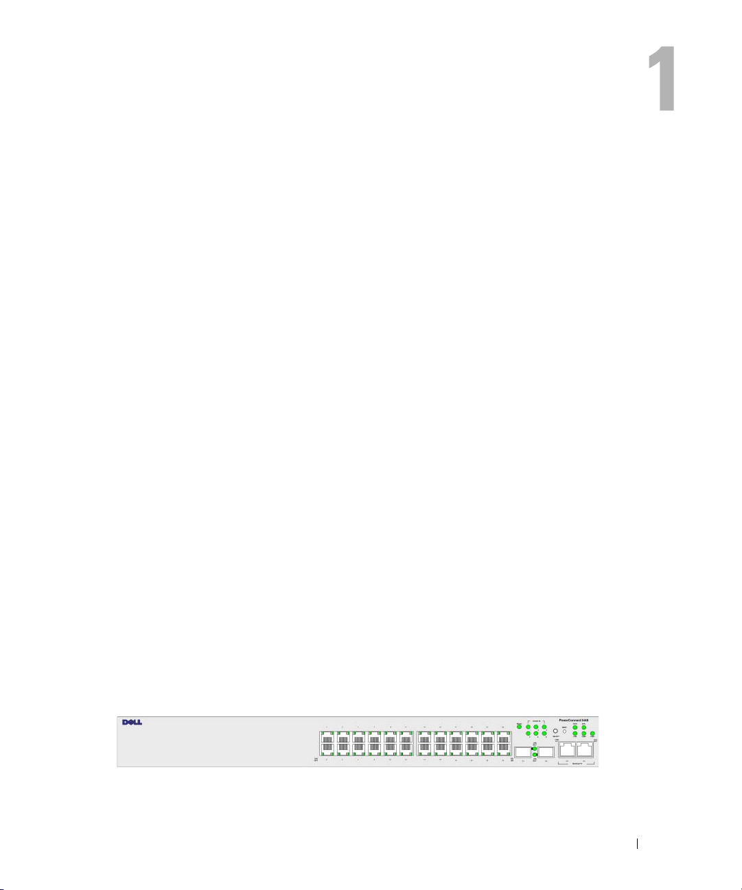
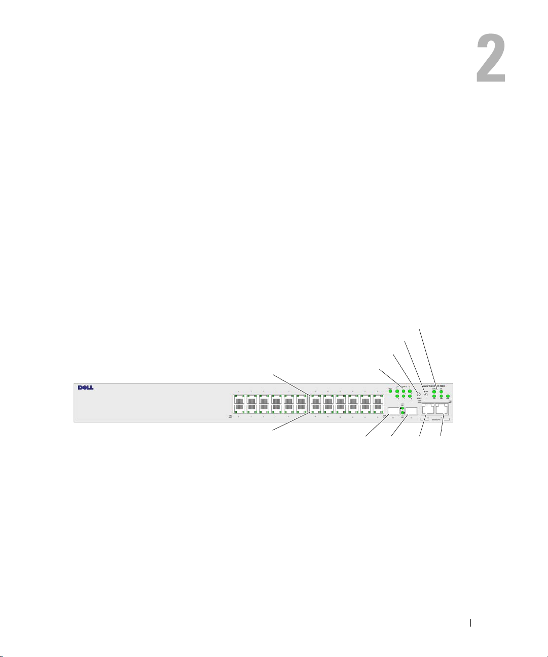
PowerConnect 3524
The PowerConnect 3524 provides 24 10/100Mbps ports plus two SFP ports, and two Copper ports
which can be used to forward traffic in a stand-alone device, or as stacking ports when the device is
stacked. The device also provides one RS-232 console port. The PowerConnect 3524 is a stackable
device, but also operates as a stand-alone device.
contains the information needed for installing, configuring, and maintaining
PowerConnect 3524P
The PowerConnect 3524P provides 24 10/100Mbps ports plus two SFP ports, and two Copper ports
which can be used to forward traffic in a stand-alone device, or as stacking ports when the device is
stacked. The device also provides one RS-232 console port. The PowerConnect 3524P is a stackable
device, but also operates as a stand-alone device. The PowerConnect 3524P also provides Power over
Ethernet (PoE).
Figure 1-1. PowerConnect 3524 and PowerConnect 3524P
Introduction 11
Page 12
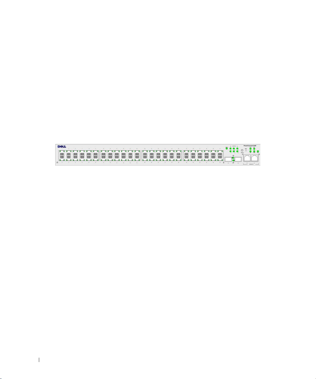
PowerConnect 3548
The PowerConnect 3548 provides 48 10/100Mbps ports plus two SFP ports, and two Copper ports which
can be used to forward traffic in a stand-alone device, or as stacking ports when the device is stacked.
The device also provides one RS-232 console port. The PowerConnect 3548 is a stackable device, but also
functions as a stand-alone device.
PowerConnect 3548P
The PowerConnect 3548P provides 48 10/100Mbps ports, two SFP ports, and two copper ports that can
be used to forward traffic when the device is in stand-alone mode, or as stacking ports when the device is
part of a stack. The device also provides one RS-232 console port. In addition, PowerConnect 3548P
provides PoE.
Figure 1-2. PowerConnect 3548 and PowerConnect 3548P
Stacking Overview
PowerConnect 3524/P and PowerConnect 3548/P stacking provides multiple switch management
through a single point as if all stack members are a single unit. All stack members are accessed through
a single IP address through which the stack is managed. The stack is managed from a:
• Web-based interface
• SNMP Management Station
• Command Line Interface (CLI)
PowerConnect 3524/P and PowerConnect 3548/P devices support stacking up to eight units per stack,
or can operate as stand-alone units.
During the Stacking setup, one switch is selected as the Stack Master and another stacking member can be
selected as the Backup Master. All other devices are selected as stack members, and assigned a unique
Unit ID.
Switch software is downloaded separately for each stack members. However, all units in the stack must be
running the same software version.
Switch stacking and configuration is maintained by the Stack Master. The Stack Master detects and
reconfigures the ports with minimal operational impact in the event of:
• Unit Failure
• Inter-unit Stacking Link Failure
• Unit Insertion
• Removal of a Stacking Unit
12 Introduction
Page 13

Understanding the Stack Topology
The PowerConnect 35xx series systems operates in a Ring topology. A stacked Ring topology is where all
devices in the stack are connected to each other forming a circle. Each device in the stack accepts data and
sends it to the device to which it is attached. The packet continues through the stack until it reaches its
destination. The system discovers the optimal path on which to send traffic.
Figure 1-3. Stacking Ring Topology
Ring Topology
Most difficulties incurred in Ring topologies occur when a device in the ring becomes non-functional,
or a link is severed. With the PowerConnect 3524/P and PowerConnect 3548/P stack, the system
automatically switches to a Stacking Failover topology without any system downtime. An SNMP message
is automatically generated, but no stack management action is required. However, the stacking link or
stacking member must be repaired to ensure the stacking integrity.
After the stacking issues are resolved, the device can be reconnected to the stack without interruption,
and the Ring topology is restored.
Stacking Failover Topology
If a failure occurs in the stacking topology, the stack reverts to Stacking Failover Topology. In the
Stacking Failover topology, devices operate in a chain formation. The Stack Master determines where the
packets are sent. Each unit is connected to two neighboring devices, except for the top and bottom units.
Stacking Members and Unit ID
Stacking Unit IDs are essential to the stacking configuration. The stacking operation is determined
during the boot process. The operation mode is determined by the Unit ID selected during the
initialization process. For example, if the user selected the stand-alone mode, the device boots in the
boot-up process as a stand-alone device.
Introduction 13
Page 14

The device units are shipped with a default Unit ID of the stand-alone unit. If the device is operating as
a stand-alone unit, all stacking LEDs are off.
Once the user selects a different Unit ID, it is not erased, and remains valid, even if the unit is reset.
Unit ID 1 and Unit ID 2 are reserved for Master enabled units. Unit IDs 3 to 8 can be defined for stack
members.
When the Master unit boots or when inserting or removing a stack member, the Master unit initiates
a stacking discovering process.
NOTE: If two members are discovered with the same Unit ID the stack continues to function, however only the unit
with the older join time joins the stack. A message is sent to the user, notifying that a unit failed to join the stack.
Removing and Replacing Stacking Members
Unit 1 and Unit 2 are Master enabled units. Unit 1 and Unit 2 are either designated as Master Unit or
Backup Master Unit. The stack Master assignment is performed during the configuration process.
One Master enabled stack member is elected as Master, and the other Master enabled stack member is
elected as Backup Master, according to the following decision process:
• If only one Stack Master enabled unit is present, it is elected as the Master.
• If two Master enabled stacking members are present, and one has been manually configured as the
Stack Master, the manually configured member is elected as Stack Master.
• If two Master enabled units are present and neither has been manually configured as the Master, the
one with the longer up-time is elected as the Stack Master.
• If two Master enabled units are present and both have been manually configured as the Master, the one
with the longer up-time is elected as the Stack Master.
• If the two Master enabled stacking members are the same age, Unit 1 is elected as the Stack Master.
NOTE: Two stacking member are considered the same age if they were inserted within a ten minute interval.
For example, Unit 2 is inserted in the first minute of a ten-minute cycle, and Unit 1 is inserted in fifth
minute of the same cycle, the units are considered to be the same age. If there are two Master enabled
stack members that are the same age, then Unit 1 is elected master.
The Stack Master and the Backup Master maintain a Warm Standby. The Warm Standby ensures that
the Backup Master takes over for the Stack Master if a failover occurs. This guarantees that the stack
continues to operate normally.
During the Warm Standby, the Master and the Backup Master are synchronized with the static
configuration only. When the Stacking Master is configured, the Stack Master must synchronize the
Stacking Backup Master. The Dynamic configuration is not saved, for example, dynamically learned
MAC addresses are not saved.
14 Introduction
Page 15

Each port in the stack has a specific Unit ID, port type, and port number, which are part of both the
configuration commands and the configuration files. Configuration files are managed only from the
device Stack Master, including:
• Saving to the FLASH
• Uploading Configuration files to an external TFTP Server/HTTP Client
• Downloading Configuration files from an external TFTP Server/HTTP Client
NOTE: Stack configuration for all configured ports is saved, even if the stack is reset and/or the ports are no
longer present.
Whenever a reboot occurs, topology discovery is performed, and the Master learns all units in the stack.
Unit IDs are saved in the unit and are learned through topology discovery. If a unit attempts to boot
without a selected Master, and the unit is not operating in stand-alone mode, the unit does not boot.
Configuration files are changed only through explicit user configuration. Configuration files are not
automatically modified when:
• Units are Added
• Units are Removed
• Units are reassigned Unit IDs
• Units toggle between Stacking Mode and Stand-alone Mode
Each time the system reboots, the Startup Configuration file in the Master unit is used to configure
the stack.
If a stack member is removed from the stack, and then replaced with a unit with the same Unit ID,
the stack member is configured with the original device configuration. Only ports which are physically
present are displayed in the PowerConnect OpenManage Switch Administrator home page, and can be
configured through the web management system. Non-present ports are configured through the CLI or
SNMP interfaces.
Exchanging Stacking Members
If a stack member with the same Unit ID replaces an existing Unit ID with the same Unit ID, the
previous device configuration is applied to the inserted stack member. If the new inserted device has
either more or fewer ports than the previous device, the relevant port configuration is applied to the new
stack member. For example,
• If a PowerConnect 3524/P replaces PowerConnect 3524/P, all port configurations remain the same.
• If a PowerConnect 3548/P replaces the PowerConnect 3548/P, all port configurations remain the same.
Introduction 15
Page 16
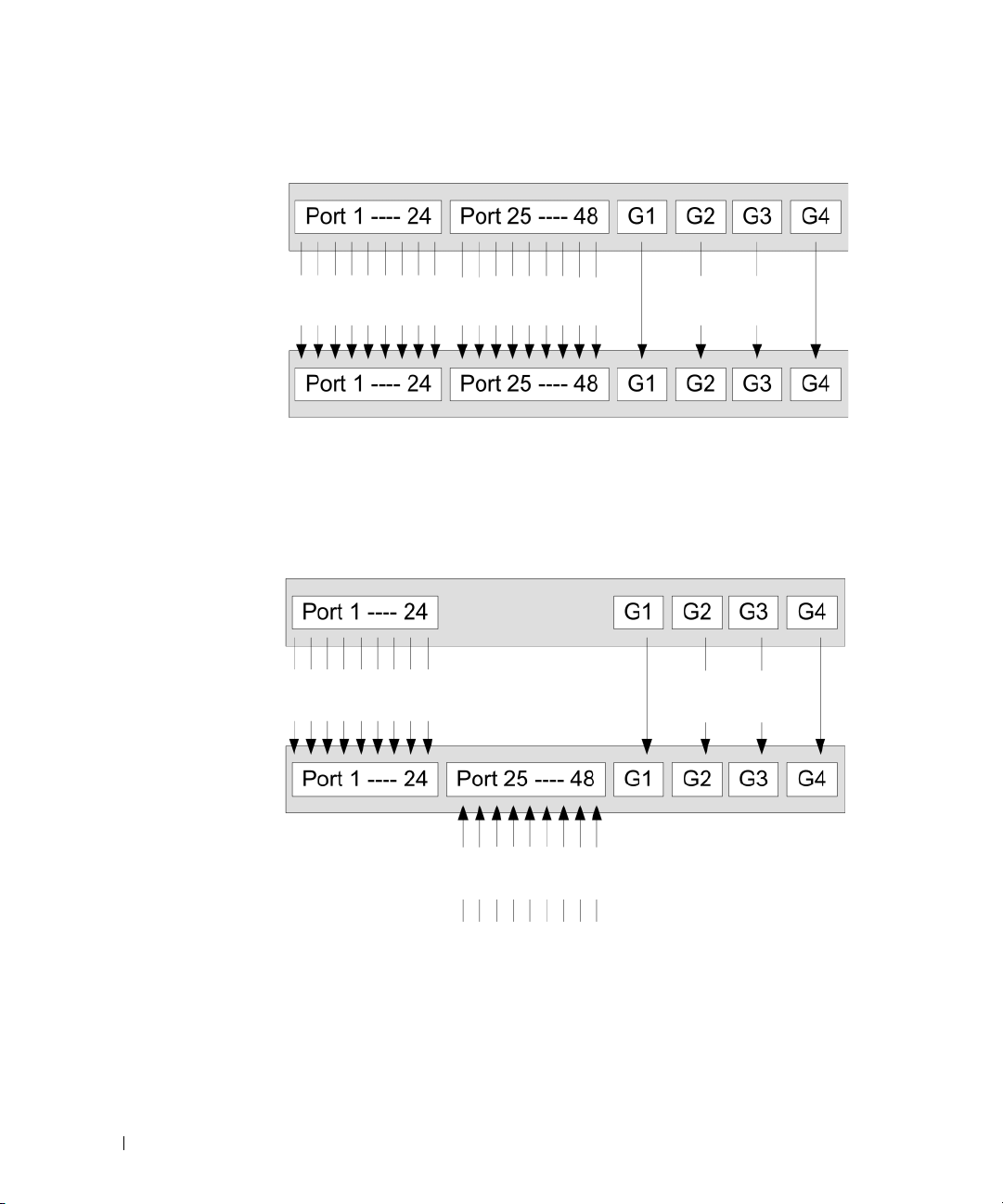
Figure 1-4. PowerConnect 3548/P replaces PowerConnect 3548/P
Same Configuration
Same Configuration
Same
Configuration
• If a PowerConnect 3548/P replaces PowerConnect 3524/P, the first 3548/P 24 FE ports receive the
3524/P 24 FE port configuration. The GE port configurations remain the same. The remaining ports
receive the default port configuration.
Figure 1-5. PowerConnect 3524/P port replaces PowerConnect 3548/P port
Same Configuration
Same Configuration
Default
Configuration
• If a PowerConnect 3524/P replaces PowerConnect 3548/P, the PowerConnect 3524/P 24 FE ports
receives the first 24 FE PowerConnect 3548/P port configuration. The GE port configurations remain
the same.
16 Introduction
Page 17
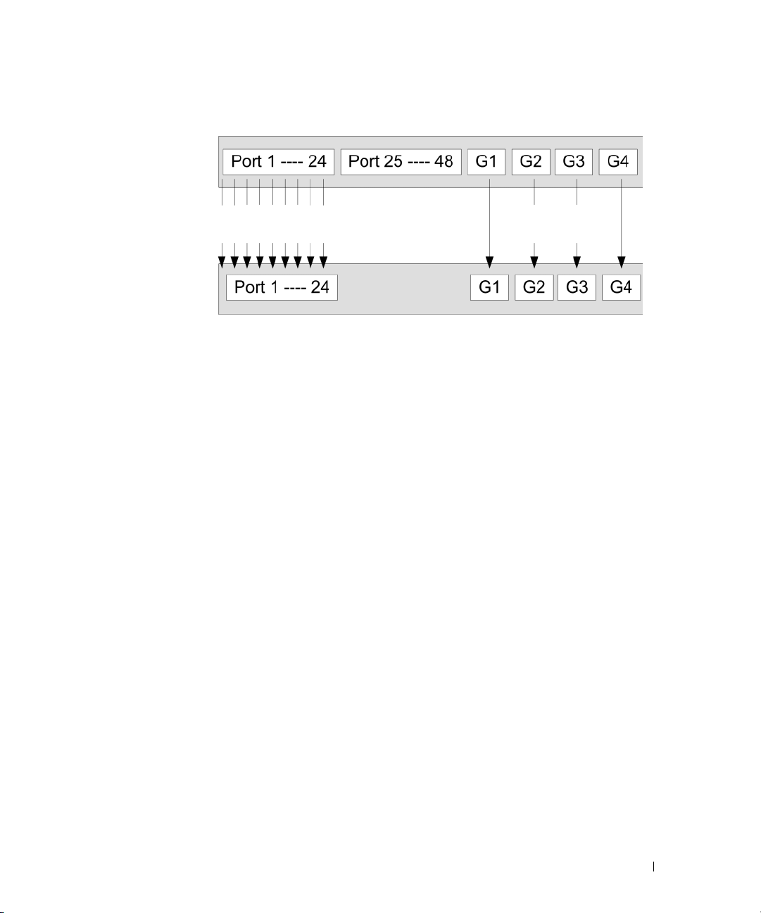
Figure 1-6. PowerConnect 3548/P port replaces PowerConect 3524/P Port
Same Configuration
Same
Configuration
Switching from the Stack Master to the Backup Stack Master
The Backup Master replaces the Stack Master if the following events occur:
• The Stack Master fails or is removed from the stack.
• Links from the Stack Master to the stacking members fails.
• A soft switchover is performed with either via web interface or the CLI.
Switching between the Stack Master and the Backup Master results in a limited service loss.
Any dynamic tables are relearned if a failure occurs. The running configuration file is synchronized
between Stack Master and the Backup Master, and continues running on the Backup Master.
Features Overview
This section describes the device features. For a complete list of all updated device features, see the latest
software version Release Notes.
IP Version 6 (IPv6) Support
The device functions as an IPv6 compliant Host, as well as an IPv4 Host (also known as dual stack).
This allows device operation in a pure IPv6 network as well as in a combined IPv4/IPv6 network.
Power over Ethernet
Power over Ethernet (PoE) provides power to devices over existing LAN cabling, without updating or
modifying the network infrastructure. PoE removes the need for placing network devices next to power
sources. PoE can be used in the following applications:
• IP Phones
• Wireless Access Points
•IP Gateways
Introduction 17
Page 18

•PDAs
• Audio and video remote monitoring
For more information about Power over Ethernet, see "Managing Power over Ethernet".
Head of Line Blocking Prevention
Head of Line (HOL) blocking results in traffic delays and frame loss caused by traffic competing for the
same egress port resources. To prevent HOL blocking the device queues packets, and the packets at the
head of the queue are forwarded before packets at the end of the queue.
Flow Control Support (IEEE 802.3X)
Flow control enables lower speed devices to communicate with higher speed devices, by requesting that
the higher speed device refrains from sending packets. Transmissions are temporarily halted to prevent
buffer overflows.
For information on configuring Flow Control for ports or LAGs, see "Defining Port Configuration" or
"Defining LAG Parameters."
Back Pressure Support
On half-duplex links, the receiving port prevents buffer overflows by occupying the link so that it is
unavailable for additional traffic.
For information on configuring Flow Control for ports or LAGs, see "Defining Port Configuration" or
"Defining LAG Parameters."
Virtual Cable Testing (VCT)
VCT detects and reports copper link cabling occurrences such as open cables and cable shorts. For more
information on testing cables, see "Running Cable Diagnostics".
MDI/MDIX Support
The device automatically detects whether the cable connected to an RJ-45 port is crossed or straight
through, when auto-negotiation is enabled.
Standard wiring for end stations is Media-Dependent Interface (MDI) and the standard wiring for hubs
and switches is known as Media-Dependent Interface with Crossover (MDIX).
For information on configuring MDI/MDIX for ports or LAGs, see "Defining Port Configuration" or
"Defining LAG Parameters."
Auto Negotiation
Auto negotiation allows the device to advertise modes of operation. The auto negotiation function
provides the means to exchange information between two devices that share a point-to-point link
segment, and to automatically configure both devices to take maximum advantage of their
transmission capabilities.
18 Introduction
Page 19

The PowerConnect 35xx series systems enhances auto negotiation by providing port advertisement.
Port advertisement allows the system administrator to configure the port speeds that are advertised.
For more information on auto-negotiation, see "Defining Port Configuration" or "Defining LAG Parameters."
Voice VLAN
Voice VLAN allows network administrators to enhance VoIP service by configuring ports to carry IP voice
traffic from IP phones on a specific VLAN. VoIP traffic has a preconfigured OUI prefix in the source
MAC address. Network Administrators can configure VLANs from which voice IP traffic is forwarded.
Non-VoIP traffic is dropped from the Voice VLAN in auto Voice VLAN secure mode. Voice VLAN also
provides QoS to VoIP, ensuring that the quality of voice does not deteriorate if the IP traffic is received
unevenly.
For more information, see "Configuring Voice VLAN" on page 374.
Guest VLAN
Guest VLAN provides limited network access to unauthorized ports. If a port is denied network access
via port-based authorization, but the Guest VLAN is enabled, the port receives limited network access.
MAC Address Supported Features
MAC Address Capacity Support
The device supports up to 8K MAC addresses. The device reserves specific MAC addresses for system
use.
Static MAC Entries
MAC entries can be manually entered in the Bridging Table, as an alternative to learning them from
incoming frames. These user-defined entries are not subject to aging, and are preserved across resets
and reboots.
For more information, see "Defining Static Addresses."
Self-Learning MAC Addresses
The device enables controlled MAC address learning from incoming packets. The MAC addresses are
stored in the Bridging Table.
Automatic Aging for MAC Addresses
MAC addresses, from which no traffic is received for a given period, are aged out. This prevents the
Bridging Table from overflowing.
For more information on configuring the MAC Address Age Out Time, see "Viewing Dynamic Addresses."
Introduction 19
Page 20

VLAN-aware MAC-based Switching
The device always performs VLAN-aware bridging. Classic bridging(IEEE802.1D) is not performed,
where frames are forwarded based only on their destination MAC address. However, a similar
functionality can be configured for untagged frames. Frames addressed to a destination MAC address
that is not associated with any port are flooded to all ports of the relevant VLAN.
MAC Multicast Support
Multicast service is a limited broadcast service, which allows one-to-many and many-to-many
connections for information distribution. Layer 2 Multicast service is where a single frame is addressed
to a specific Multicast address, from where copies of the frame are transmitted to the relevant ports.
When Multicast groups are statically enabled, you can set the destination port of registered groups,
as well as define the behavior of unregistered multicast frames.
For more information, see "Assigning Multicast Forward All Parameters."
Layer 2 Features
IGMP Snooping
Internet Group Membership Protocol (IGMP) Snooping examines IGMP frame contents, when they are
forwarded by the device from work stations to an upstream Multicast router. From the frame, the device
identifies work stations configured for Multicast sessions, and which Multicast routers are sending
Multicast frames. IGMP Querier simulates the behavior of a multicast router; this allows snooping of the
layer 2 multicast domain even if there is no multicast router.
For more information, see "IGMP Snooping."
Port Mirroring
Port mirroring monitors and mirrors network traffic by forwarding copies of incoming and outgoing
packets from a monitored port to a monitoring port. Users specify which target port receives copies of all
traffic passing through a specified source port.
For more information, see "Defining Port Mirroring Sessions."
Broadcast Storm Control
Storm Control enables limiting the amount of Multicast and Broadcast frames accepted and forwarded
by the device.
When Layer 2 frames are forwarded, Broadcast and Multicast frames are flooded to all ports on the
relevant VLAN. This occupies bandwidth, and loads all nodes connected on all ports.
For more information, see "Enabling Storm Control."
20 Introduction
Page 21

VLAN Supported Features
VLAN Support
VLANs are collections of switching ports that comprise a single broadcast domain. Packets are classified
as belonging to a VLAN based on either the VLAN tag or based on a combination of the ingress port and
packet contents. Packets sharing common attributes can be grouped in the same VLAN.
For more information, see "Configuring VLANs."
Port Based Virtual LANs (VLANs)
Port-based VLANs classify incoming packets to VLANs based on their ingress port.
For more information, see "Defining VLAN Ports Settings."
Full 802.1Q VLAN Tagging Compliance
IEEE 802.1Q defines an architecture for virtual bridged LANs, the services provided in VLANs, and the
protocols and algorithms involved in the provision of these services.
GVRP Support
GARP VLAN Registration Protocol (GVRP) provides IEEE 802.1Q-compliant VLAN pruning and
dynamic VLAN creation on 802.1Q trunk ports. When GVRP is enabled, the device registers and
propagates VLAN membership on all ports that are part of the active underlying "Spanning Tree
Protocol Features" on page 21 topology.
For more information, see "Configuring GVRP Parameters."
Private VLAN Edge
Ports can be assigned to Private VLAN Edge (PVE) groups. A port defined as PVE is protected by an
uplink, so that it is isolated from other ports within the same VLAN. The uplink must be a GE port.
For more information on Private VLANs, see "Configuring Ports" on page 297.
Spanning Tree Protocol Features
Spanning Tree Protocol (STP)
802.1d Spanning tree is a standard Layer 2 switch requirement that allows bridges to automatically
prevent and resolve L2 forwarding loops. Switches exchange configuration messages using specifically
formatted frames and selectively enable and disable forwarding on ports.
For more information, see "Configuring the Spanning Tree Protocol."
Introduction 21
Page 22

Fast Link
STP can take up to 30-60 seconds to converge. During this time, STP detects possible loops, allowing
time for status changes to propagate and for relevant devices to respond. 30-60 seconds is considered too
long of a response time for many applications. The Fast Link option bypasses this delay, and can be used
in network topologies where forwarding loops do not occur.
For more information enabling Fast Link for ports and LAGs, see "Defining STP Port Settings" or
"Defining Static Addresses."
IEEE 802.1w Rapid Spanning Tree
Spanning Tree can take 30-60 seconds for each host to decide whether its ports are actively forwarding
traffic. Rapid Spanning Tree (RSTP) detects uses of network topologies to enable faster convergence,
without creating forwarding loops.
For more information, see "Defining Rapid Spanning Tree."
IEEE 802.1s Multiple Spanning Tree
Multiple Spanning Tree (MSTP) operation maps VLANs into STP instances. MSTP provides differing
load balancing scenario. Packets assigned to various VLANs are transmitted along different paths within
MSTP Regions (MST Regions). Regions are one or more MSTP bridges by which frames can be
transmitted. The standard lets administrators assign VLAN traffic to unique paths.
For more information, see "Configuring the Spanning Tree Protocol."
Link Aggregation
Link Aggregation
Up to eight Aggregated Links may be defined, each with up to eight member ports, to form a single Link
Aggregated Group (LAG). This enables:
• Fault tolerance protection from physical link disruption
• Higher bandwidth connections
• Improved bandwidth granularity
• High bandwidth server connectivity
LAG is composed of ports with the same speed, set to full-duplex operation.
For more information, see "Defining LAG Parameters."
Link Aggregation and LACP
LACP uses peer exchanges across links to determine, on an ongoing basis, the aggregation capability of
various links, and continuously provides the maximum level of aggregation capability achievable between
a given pair of devices. LACP automatically determines, configures, binds, and monitors the port binding
within the system.
For more information, see "Aggregating Ports."
22 Introduction
Page 23

BootP and DHCP Clients
DHCP enables additional setup parameters to be received from a network server upon system startup.
DHCP service is an on-going process. DHCP is an extension to BootP.
For more information on DHCP, see "Defining DHCP IPv4 Interface Parameters."
Quality of Service Features
Class Of Service 802.1p Support
The IEEE 802.1p signaling technique is an OSI Layer 2 standard for marking and prioritizing network
traffic at the data link/MAC sub-layer. 802.1p traffic is classified and sent to the destination.
No bandwidth reservations or limits are established or enforced. 802.1p is a spin-off of the
802.1Q (VLANs) standard. 802.1p establishes eight levels of priority, similar to the IP Precedence
IP Header bit-field.
For more information, see "Configuring Quality of Service."
Device Management Features
SNMP Alarms and Trap Logs
The system logs events with severity codes and timestamps. Events are sent as SNMP traps to a Trap
Recipient List.
For more information on SNMP Alarms and Traps, see "Defining SNMP Parameters."
SNMP Versions 1, 2 and 3
Simple Network Management Protocol (SNMP) over the UDP/IP protocol controls access to the system,
a list of community entries is defined, each of which consists of a community string and its access
privileges. There are 3 levels of SNMP security read-only, read-write, and super. Only a super user can
access the community table.
For more information, see "Defining SNMP Parameters".
Web Based Management
With the web based management, the system can be managed from any web browser. The system
contains an Embedded Web Server (EWS), which serves HTML pages, through which the system can be
monitored and configured. The system internally converts web-based input into configuration
commands, MIB variable settings and other management-related settings.
Configuration File Download and Upload
The device configuration is stored in a configuration file. The Configuration file includes both system
wide and port specific device configuration. The system can display configuration files in the form of a
collection of CLI commands, which are stored and manipulated as text files.
For more information, see "Managing Files."
Introduction 23
Page 24

TFTP Trivial File Transfer Protocol
The device supports boot image, software, and configuration upload/download via TFTP.
Remote Monitoring
Remote Monitoring (RMON) is an extension to SNMP, which provides comprehensive network traffic
monitoring capabilities (as opposed to SNMP which allows network device management and
monitoring). RMON is a standard MIB that defines current and historical MAC-layer statistics and
control objects, allowing real-time information to be captured across the entire network.
For more information, see "Viewing Statistics."
Command Line Interface
Command Line Interface (CLI) syntax and semantics conform as much as possible to common industry
practice. CLI is composed of mandatory and optional elements. The CLI interpreter provides command
and keyword completion to assist user and shorten typing.
Syslog
Syslog is a protocol that enables event notifications to be sent to a set of remote servers, where they can
be stored, examined and acted upon. The system sends notifications of significant events in real time,
and keeps a record of these events for after-the-fact usage.
For more information on Syslog, see "Managing Logs."
SNTP
The Simple Network Time Protocol (SNTP) assures accurate network Ethernet Switch clock time
synchronization up to the millisecond. Time synchronization is performed by a network SNTP server.
Time sources are established by Stratums. Stratums define the distance from the reference clock.
The higher the stratum (where zero is the highest), the more accurate the clock.
For more information, see "Configuring SNTP Settings."
Domain Name System
Domain Name System (DNS) converts user-defined domain names into IP addresses. Each time a
domain name is assigned the DNS service translates the name into a numeric IP address. For example,
www.ipexample.com is translated to 192.87.56.2. DNS servers maintain domain name databases and
their corresponding IP addresses.
For more information, see "Configuring Domain Name Systems" on page 154.
Traceroute
Traceroute discovers IP routes that packets were forwarded along during the forwarding process. The CLI
Traceroute utility can be executed from either the user-exec or privileged modes.
24 Introduction
Page 25

802.1ab (LLDP-MED)
The Link Layer Discovery Protocol (LLDP) allows network managers to troubleshoot and enhance
network management by discovering and maintaining network topologies over multi-vendor
environments. LLDP discovers network neighbors by standardizing methods for network devices to
advertise themselves to other systems, and to store discovered information. The multiple advertisement
sets are sent in the packet Type Length Value (TLV) field. LLDP devices must support chassis and port
ID advertisement, as well as system name, system ID, system description, and system capability
advertisements.
LLDP Media Endpoint Discovery (LLDP-MED) increases network flexibility by allowing different
IP systems to co-exist on a single network LLDP. It provides detailed network topology information,
emergency call service via IP Phone location information, and troubleshooting information.
Security Features
SSL
Secure Socket Layer (SSL) is an application-level protocol that enables secure transactions of data
through privacy, authentication, and data integrity. It relies upon certificates and public and private keys.
Port Based Authentication (802.1x)
Port based authentication enables authenticating system users on a per-port basis via an external server.
Only authenticated and approved system users can transmit and receive data. Ports are authenticated via
the Remote Authentication Dial In User Service (RADIUS) server using the Extensible Authentication
Protocol (EAP). Dynamic VLAN Assignment (DVA) allows network administrators to automatically
assign users to VLANs during the RADIUS server authentication.
For more information, see "Port Based Authentication."
Locked Port Support
Locked Port increases network security by limiting access on a specific port only to users with specific
MAC addresses. These addresses are either manually defined or learned on that port. When a frame is
seen on a locked port, and the frame source MAC address is not tied to that port, the protection
mechanism is invoked.
For more information, see "Configuring Port Security."
RADIUS Client
RADIUS is a client/server-based protocol. A RADIUS server maintains a user database, which contains
per-user authentication information, such as user name, password and accounting information.
For more information, see "Configuring RADIUS Settings."
Introduction 25
Page 26

SSH
Secure Shell (SSH) is a protocol that provides a secure, remote connection to a device. SSH version 2 is
currently supported. The SSH server feature enables an SSH client to establish a secure, encrypted
connection with a device. This connection provides functionality that is similar to an inbound telnet
connection. SSH uses RSA and DSA Public Key cryptography for device connections and authentication.
TAC ACS+
TACACS+ provides centralized security for validation of users accessing the device. TACACS+ provides
a centralized user management system, while still retaining consistency with RADIUS and other
authentication processes.
For more information, see "Defining TACACS+ Settings."
Password Management
Password management provides increased network security and improved password control. Passwords
for SSH, Telnet, HTTP, HTTPS, and SNMP access are assigned security features. For more information
on Password Management, see "Managing Passwords".
Access Control Lists (ACL)
Access Control Lists (ACL) allow network managers to define classification actions and rules for specific
ingress ports. Packets entering an ingress port, with an active ACL, are either admitted or denied entry
and the ingress port is disabled. If they are denied entry, the user can disable the port.
For more information, see "ACL Overview" on page 276.
DHCP Snooping
DHCP Snooping expands network security by providing firewall security between untrusted interfaces
and DHCP servers. By enabling DHCP Snooping network administrators can differentiate between
trusted interfaces connected to end-users or DHCP Servers and untrusted interfaces located beyond the
network firewall.
For more information, see "Configuring DHCP Snooping" on page 288.
Additional CLI Documentation
The CLI Reference Guide, which is available on the Documentation CD, provides information about the
CLI commands used to configure the device. The document provides information about the command
description, syntax, default values, guidelines, and examples.
26 Introduction
Page 27
Hardware Description
Port Description
PowerConnect 3524 Port Description
The Dell™ PowerConnect™ 3524 device is configured with the following ports:
•
24 Fast Ethernet ports
•
2 Fiber ports
2 Gigabit ports
•
•
Console port
The following figure illustrates the PowerConnect 3524 front panel.
Figure 2-1. PowerConnect 3524 Front Panel
— Designated as 1000Base-X SFP ports
— Designated as 1000Base-T ports
— RS-232 based port
10/100 Base-T Ports 1, 3, 5, 7, ...23
— RJ-45 ports designated as 10/100Base-T ports
System LEDs
Reset Button
Stacking Button
Stacking LEDs
10/100 Base-T Ports 2, 4, 6, 8, ...24
The front panel contains 24 RJ-45 ports number 1-24. The upper row of ports is marked with
odd numbers 1-23, and the lower row of ports is marked with even numbers 2-24. In addition,
the front panel also contains ports G1 - G2 which are fiber ports and ports G3- G4 which are
copper ports. Ports G3 - G4 can either be used as stacking ports, or used to forward network traffic
in a stand-alone device.
G1
G2
G3
1000Base-X
SFP Ports
Stacking
Ports
Hardware Description 27
G4
Page 28
There are two buttons on the front panel. The Stack ID button is used to select the unit number.
The second button is the Reset Button which is used to manually reset the device. The Reset button
does not extend beyond the unit’s front panel surface, so reset by pressing it accidentally is prevented.
On the front panel are all the device LEDs.
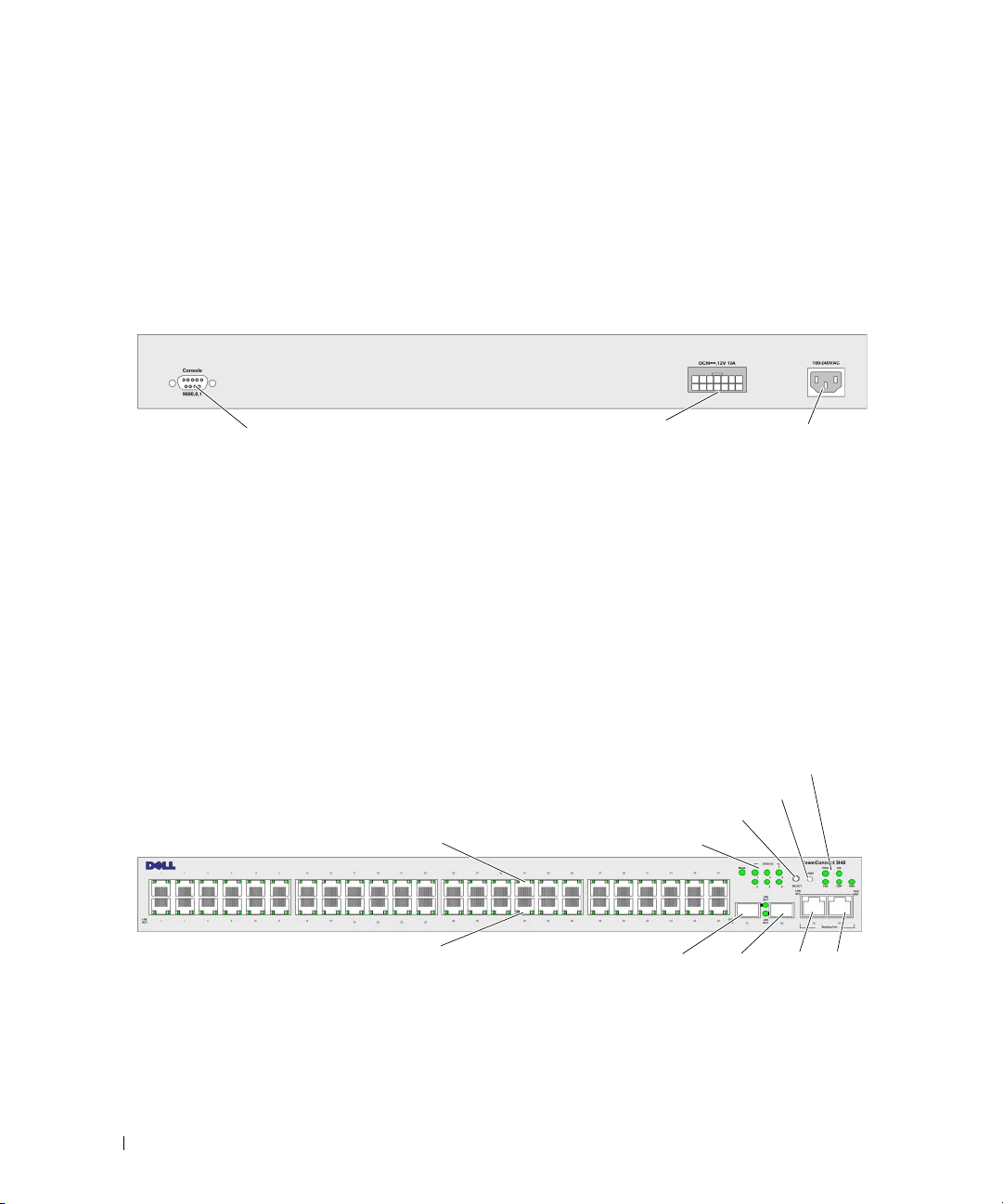
The following figure illustrates the PowerConnect 3524 back:
Figure 2-2. PowerConnect 3524 Back Panel
Console Port
RPS Connector
Power Connector
The back panel contains an RPS connector, console port, and power connector.
PowerConnect 3548 Port Description
The PowerConnect 3548 device is configured with the following ports:
•
48 FE ports
2 Fiber ports
•
•
2 Gigabit ports
•
Console port
The following figure illustrates the PowerConnect 3548 front panel.
Figure 2-3. PowerConnect 3548 Front Panel
10/100 Base-T Ports 2, 4, 6, 8, ...48
— RJ-45 ports designated as 10/100Base-T ports
— Designated as 1000Base-X SFP ports
— Designated as 1000Base-T ports
— RS-232 Console based port
10/100 Base-T Ports 1, 3, 5, 7, ...47
Stacking Button
Stacking LEDs
G1
1000Base-X
SFP Ports
System LEDs
Reset Button
G2
G3
G4
Stacking
Ports
28 Hardware Description
Page 29

The front panel contains 48 RJ-45 ports number 1-48. The upper row of ports is marked by odd numbers
1-47, and the lower row of ports is marked with even numbers 2-48. In addition, the front panel also
contains ports G1 - G2 which are fiber ports and ports G3- G4 which are copper ports. Ports G3- G4 can
either be used as stacking ports, or used to forward network traffic in a stand-alone device.
There are two buttons on the front panel. The Stack ID button is used to select the unit number.
The second button is the Reset Button which is used to manually reset the device. The Reset button
does not extend beyond the unit’s front panel surface, so reset by pressing it accidentally is prevented.
On the front panel are all the device LEDs.
The following figure illustrates the PowerConnect 3548 back panel:
Figure 2-4. PowerConnect 3548 Back Panel
Console Port
RPS Connector
Power Connector
The back panel contains an RPS connector, console port and power connector.
SFP Ports
The Small Form Factor Plugable (SFP) ports are fiber transceivers designated as 10000 Base-SX or LX.
They include TWSI (Two-Wire Serial Interface) and internal EPROM.
RS-232 Console Port
One DB-9 connector for a terminal connection is used for debugging, software download etc.
The default baud rate is 9,600 bps. The baud rate can be configured from 2400 bps up to 115,200 bps.
Figure 2-5. Console Port
Hardware Description 29
Page 30

Physical Dimensions
The PowerConnect 3524/P and PowerConnect 3548/P devices have the following physical dimensions:
PoE Model:
•
Width
— 440 mm (17.32 inch)
Depth
•
•
Non-PoE Device:
•
•
•
— 387 mm (15.236 inch)
Height
Width
Depth
Height
— 43.2 mm (1.7 inch)
— 440 mm (17.32 inch)
— 257 mm (10.118 inch)
— 43.2 mm (1.7 inch)
LED Definitions
The front panel contains light emitting diodes (LED) that indicate the status of links, power supplies,
fans, and system diagnostics.
Port LEDs
Each 10/100/1000 Base-T port and 10/100 Base-T port has two LEDs. The speed LED is located on the
left side of the port, while the link/duplex/activity LED is located on the right side.
The following figure illustrates the 10/100 Base-T port LEDs on The PowerConnect 3524 /P and
PowerConnect 3548/P switches:
Figure 2-6. RJ-45 Copper Based 10/100 BaseT LEDs
Speed/LNK/ACT
Speed/LNK/ACT
The RJ-45 100 Base-T port on the PowerConnect 3524 /P and PowerConnect 3548/P has two LEDs
marked as LNK/ACT.
30 Hardware Description
FDX
FDX
Page 31

The following figure illustrates the 100 Base-T LEDs.
Figure 2-7. RJ-45 1000 BaseT LED
The RJ-45 LED indications for PowerConnect 3524 and PowerConnect 3548 are described in the
following table:
Table 2-1. PowerConnect 3524 and PowerConnect 3548 RJ-45 100BaseT LED Indications
LED Color Description
Link/Activity/Speed Green Static The port is running at 100 Mbs.
Green Flashing The port is either transmitting or receiving data at 100 Mbps.
Amber Static The port is running at 10 Mbs.
Yellow Flashing The port is either transmitting or receiving data at 10 Mbps.
OFF The port is currently not operating.
FDX Green Static The port is currently operating in Full Duplex mode.
OFF The port is currently operating in Half Duplex mode,
Hardware Description 31
Page 32

The RJ-45 LED indications for PowerConnect 3524P and PowerConnect 3548P are described in the
following table:
Table 2-2. PowerConnect 3524P and PowerConnect 3548P RJ-45 Copper based 100BaseT LED Indications
LED Color Description
Speed/Link/Act Green Static The port is currently linked at 100 Mbps.
Green Flashing The ports is currently operating at 100 Mbps.
OFF The port is currently operating at 10 Mbps or is not linked.
FDX Green Static The Powered Device (PD) is detected and is operating at normal load. For more
information about Powered Devices, see "Managing Power over Ethernet".
Green Flashing The port is operating at transitional mode. The PD is being detected, or is faulty.
For more information about Power over Ethernet, see "Managing Power over
Ethernet".
Amber Static An overload or short has occurred on the Powered Device. For more information
about Power over Ethernet faults, see "Managing Power over Ethernet".
Amber
Flashing
OFF No powered device is detected.
The powered device power conception exceeds the predefined power allotment.
For more information about Power over Ethernet power allotments, see
"Managing Power over Ethernet".
Gigabit Port LEDs
The following table describes the Gigabit (stacking port) LEDs:
Table 2-3. PowerConnect 3524 and PowerConnect 3548 RJ-45 Copper based 100BaseT LED Indications
LED Color Description
Link/Activity/Speed Green Static The port is running at 1000 Mbs.
Green Flashing The port is either transmitting or receiving data at 1000 Mbps.
Yellow Static The port is running at 10 or 100Mbs.
Yellow Flashing The port is either transmitting or receiving data at 10 or 100 Mbps.
OFF The port is currently not operating.
FDX Green Static The port is currently operating in Full Duplex mode.
OFF The port is currently operating in Half Duplex mode.
32 Hardware Description
Page 33

SFP LEDs
The SFP ports each have one LED marked as LNK/ACT. On the PowerConnect 3524/P and
PowerConnect 3548/P devices, the LEDs are located between ports and are round in shape.
The following figures illustrate the LEDs on each device.
Figure 2-8. SFP Port LEDs
The SFP port LED indications are described in the following table:
Table 2-4. SFP Port LED Indications
LED Color Description
Link/Activity Green Static A link is established.
Green Flashing The port is currently transmitting or receiving data.
OFF The port is currently not linked.
System LEDs
The system LEDs of The PowerConnect 3524 /P and PowerConnect 3548/P devices provide information
about the power supplies, fans, thermal conditions, and diagnostics. The following figure illustrates the
system LEDS.
Figure 2-9. System LEDs
Hardware Description 33
Page 34

The following table describes the system LED indications.
Table 2-5. System LED Indicators
LED Color Description
Power Supply (PWR) Green Static The switch is turned on.
OFF The switch is turned off.
Redundant Power Supply (RPS)
(models: 3524 and 3548 )
Redundant Power Supply (RPS)
(models: 3524P and 3548P )
Diagnostics (DIAG) Green Flashing The system diagnostic test is currently in progress.
Temperature (TEMP) Red Static The device has crossed the permitted temperature
Fan (FAN) Green Static All device fans are operating normally.
Green Static The RPS is currently operating.
Red Static The RPS failed.
OFF The redundant power supply is not plugged in.
Green Static The RPS is currently operating.
OFF The redundant power supply has failed or is not
plugged in.
Green Static The system diagnostic test passed successfully.
Red Static The system diagnostic test failed.
OFF The system is operating normally.
range.
OFF The device is operating within the permitted
temperature range.
Red Static One or more of the device fans is not operating.
The Stacking LEDs indicate the unit position in the stack. The following figure illustrates the LEDs on
the front panel.
Figure 2-10. Stacking LEDs
34 Hardware Description
Page 35

The Stacking LEDs are numbered 1- 8. Each stacking unit has one stacking LED lit, indicating its Unit
ID number. If either Stacking LED 1 or 2 is lit, it indicates that the device is either the Stack Master or
Backup Master.
Table 2-6. Stacking LED Indications
LED Color Description
All Stacking LEDs OFF The switch is currently a stand-alone device.
Stacking LED 1-8 (S1-S8) Green Static The device is designated as Stacking Unit N.
OFF The device is not designated as Stacking Unit N.
Stacking Master LED Green Static The device is the Stack Master
OFF The device is not the Stack Master.
Power Supplies
The device has an internal power supply unit (AC unit) and a connector to connect PowerConnect
3524/P and PowerConnect 3548/P devices to a PowerConnect EPS-470 unit, or to connect
PowerConnect 3524 and PowerConnect 3548 devices to a PowerConnect RPS-600 unit.
The PowerConnect 3524/P and PowerConnect 3548/P devices have an internal power supply (12 Volt).
Operation with both power supply units is regulated through load sharing. Power supply LEDs indicate
the status of the power supply.
The PowerConnect 3524/P and PowerConnect 3548/P devices have an internal power supply of 470W
(12V/-48V), with a total of 370W for 24 ports PoE device.
AC Power Supply Unit
The AC power supply unit operates from 90 to 264 VAC, 47 to 63 Hz. The AC power supply unit uses a
standard connector. LED indicator is on the front panel and indicates whether the AC unit is connected.
DC Power Supply Unit
The PowerConnect 3524 and PowerConnect 3548 switches connect to an external RPS-600 unit to
provide a redundant power option. No configuration is required. The front panel "RPS" LED indicates
whether the external RPS-600 is connected. See Table 2-5 for RPS LED definition.
The PowerConnect 3524/P and PowerConnect 3548/P switches connect to an external EPS-470 unit to
provide a redundant power option. No configuration is required. The front panel "RPS" LED indicates
whether the external EPS-470 is connected. See Table 2-5 for RPS LED definition.
Hardware Description 35
Page 36

Figure 2-11. Power Connection
When the device is connected to a different power source, the probability of failure in the event of a
power outage decreases.
Stack ID Button
The device front panel contains a Stack ID button used to manually select the Unit ID for the Stack
Master and members.
The Stack Master and members must be selected within 15 seconds of booting the device. If the Stack
Master is not selected within 15 seconds, the device is booted in stand-alone mode. To select a Unit ID
for the device, reboot the device.
The Stack Master receives the Unit ID of 1 or 2. If both Unit 1 and Unit 2 are present, the unit that is not
elected functions as the Backup Master. Stack members receive a separate Unit ID (3-8). For example,
if there are four units in a stack, the Master unit is either 1 or 2, the backup Master is either 1 or 2
depending on the Unit ID of the Master unit, the third member is 3, and the fourth Stack member is 4.
NOTE: The device does not automatically detect a stand-alone unit. If a Unit ID has already been selected, press
the Stack ID button several times until no stacking LED is lit.
36 Hardware Description
Page 37

Reset Button
The PowerConnect 3524/P and PowerConnect 3548/P switches have a reset button, located on the front
panel, for manual reset of the device. If the Master device is reset, the entire stack is reset. If only a
member unit is reset, the remain stacking members are not reset.
The single reset circuit of the switch is activated by power-up or low-voltage conditions.
Ventilation System
The PowerConnect 3524/P and PowerConnect 3548/P switches with the PoE feature have five built-in
fans. The non-PoE PowerConnect 3524 and PowerConnect 3548 devices have two built-in fans.
Operation can be verified by observing the LED that indicates if one or more fans is faulty.
Hardware Description 37
Page 38

38 Hardware Description
Page 39

Installing the PowerConnect 3524/P and PowerConnect 3548/P
Site Preparation
The Dell™ PowerConnect™ 3524 /P and PowerConnect 3548/P devices can be mounted in a standard
48.26-am (19-inch) equipment rack, placed on a tabletop or mounted on a wall. Before installing the
unit, verify that the chosen location for installation meets the following site requirements:
•
Power
— The unit is installed near an easily accessible 100-240 VAC, 50-60 Hz outlet.
•
General
on the front panel are illuminated.
• PoE Models
are illuminated.
•
Clearance
power connections, and ventilation.
•
Cabling
broadcast amplifiers, power lines, and fluorescent lighting fixtures.
•
Ambient Requirements
113ºF) at a relative humidity of 10% to 90%, non-condensing.
— The Redundant Power Supply (RPS) is correctly installed by checking that the LEDs
— The RPS is currently installed by checking that the PoE LEDs on the front panel
— There is adequate frontal clearance for operator access. Allow clearance for cabling,
— The cabling is routed to avoid sources of electrical noise such as radio transmitters,
— The ambient unit operating temperature range is 0 to 45ºC (32 to
Unpacking
Package Contents
While unpacking the device, ensure that the following items are included:
• Device/Switch
• AC power cable
• RS-232 crossover cable
• Self-adhesive rubber pads
Installing the PowerConnect 3524/P and PowerConnect 3548/P 39
Page 40

• Rack-mount kit for rack installation or wall mounting kit
• Documentation CD
• Product Information Guide
Unpacking the Device
NOTE: Before unpacking the device, inspect the package and immediately report any evidence of damage.
1
Place the box on a clean flat surface.
2
Open the box or remove the box top.
3
Carefully remove the device from the box and place it on a secure and clean surface.
4
Remove all packing material.
5
Inspect the device and accessories for damage. Report any damage immediately.
Mounting the Device
The following mounting instructions apply to The PowerConnect 3524/P and PowerConnect 3548/P
devices. The Console port is on the back panel. The power connectors are positioned on the back panel.
Connecting a Redundant Power Supply (RPS) is optional, but is recommended. The RPS connector is
on the back panel of the devices.
Installing in a Rack
WARNING: Read the Safety Information included in the Product Information Guide for safety information on
devices connected to or that support the SWI.
WARNING: Disconnect all cables from the unit before mounting the device in a rack or cabinet.
WARNING: When mounting multiple devices into a rack, mount the devices from the bottom up.
40 Installing the PowerConnect 3524/P and PowerConnect 3548/P
Page 41

1
Place the supplied rack-mounting bracket on one side of the device, ensuring that the mounting holes
on the device line up to the mounting holes on the rack-mounting bracket.
The following figure illustrates where to mount the brackets.
Figure 3-1. Bracket Installation for Rack Mounting
2
Insert the supplied screws into the rack-mounting holes and tighten with a screwdriver.
3
Repeat the process for the rack-mounting bracket on the other side of the device.
4
Insert the unit into the 48.26 cm (19 inch) rack, ensuring that the rack-mounting holes on the device
line up to the mounting holes on the rack.
5
Secure the unit to the rack with the rack screws (not provided). Fasten the lower pair of screws before
the upper pair of screws. Ensure that the ventilation holes are not obstructed.
Installing on a Flat Surface
The device must be installed on a flat surface if it is not installed on a rack. The surface must be able to
support the weight of the device and the device cables.
1
Attach the self-adhesive rubber pads on each marked location on the bottom of the chassis.
2
Set the device on a flat surface, leaving 5.08 cm (2 inch) on each side and 12.7 cm (5 inch) at the back.
3
Ensure that the device has proper ventilation.
Installing the PowerConnect 3524/P and PowerConnect 3548/P 41
Page 42

Installing the Device on a Wall
1
Place the supplied wall-mounting bracket on one side of the device, ensuring that the mounting holes
on the device line up to the mounting holes on the rack-mounting bracket. The following figure
illustrates where to mount the brackets.
Figure 3-2. Bracket Installation for Mounting on a Wall
2
Insert the supplied screws into the rack-mounting holes and tighten with a screwdriver.
3
Repeat the process for the wall-mounting bracket on the other side of the device.
4
Place the device on the wall in the location where the device is being installed.
5
On the wall mark the locations where the screws to hold the device must be prepared.
6
Drill holes and place all plugs (not provided) in the holes, in the marked location.
7
Secure the unit to the wall with screws (not provided). Ensure that the ventilation holes are not
obstructed.
42 Installing the PowerConnect 3524/P and PowerConnect 3548/P
Page 43

Figure 3-3. Mounting a Device on a Wall
Fro n t P a n el
Drilled
Holes
Wal l
Drilled
Holes
Connecting to a Terminal
1
Connect an RS-232 crossover cable to the ASCII terminal or the serial connector of a desktop system
running terminal emulation software.
2
Connect the female DB-9 connector at the other end of the cable to the device serial port connector.
Installing the PowerConnect 3524/P and PowerConnect 3548/P 43
Page 44

Connecting a Device to a Power Supply
Connect the supplied AC power cable to the AC power connector on the back panel.
NOTE: Do not connect the power cable to a grounded AC outlet at this time. Connect the device to a power source
in the steps detailed in "Starting and Configuring the Device" on page 47.
Figure 3-4. Back-Panel Power Connector
Console Port
PowerConnect 3524/3548 Rear View
Console Port
PowerConnect 3524P/3548P Rear View
After connecting the device to a power source, confirm that the device is connected and operating
correctly by examining the LEDs on the front panel.
RPS Connector
EPS Connector
Power Connector
Power Connector
Installing a Stack
Overview
Each device can operate as a stand-alone device or can be a member in a stack. Up to eight devices or up
to 384 ports are supported per stack.
All stacks must have a Master unit, and may have a Master Backup unit, with any other devices
connected to the stack as Members.
44 Installing the PowerConnect 3524/P and PowerConnect 3548/P
Page 45

Stacking PowerConnect 35xx Series Systems Switches
Each PowerConnect 35xx series systems stack contains a single Master unit, and may have a Master
Backup unit, while the remaining units are considered stacking Members.
PowerConnect 35xx series systems switches use the RJ-45 Gigabit Ethernet ports (G3 and G4) for
stacking. This enables added stacking capabilities to the devices without adding additional device
accessories. To stack the devices together, insert a standard Category 5 cable into port G3 in the
uppermost device in the stack, and into port G4 of the device immediately below it in the stack. Repeat
this process until all devices are connected. Connect the bottommost device’s port G3 in the stack to
port G4 of the uppermost device in the stack.
Figure 3-5. Stacking Cable Diagram
NOTE: In stacking mode ports designated as G3 and G4 are not displayed in the EWS. The effect is of not being
present on the device. This is because the ports receive a different index for stacking.
Stack unit identification is performed on the device front panel using the Stack ID button.
Installing the PowerConnect 3524/P and PowerConnect 3548/P 45
Page 46

Figure 3-6. Stacking Configuration and Identification Panel
Each stack device has a unique identifying unit ID that defines the unit’s position and function in
the stack. If the device is a stand-alone unit, the Stack LED is not illuminated. The default setting
is stand-alone.
The unit ID is manually configured by using the Stack ID button. The unit ID is indicated by the Stack
ID LEDs. Unit ID 1 and 2 are reserved for the Master and Backup Master unit, and unit ID 3 to 8 are for
Member units.
Unit ID Selection Process
The unit ID selection process is as follows:
1
Ensure that the stand-alone/Master device Console port is connected to a VT100 terminal device or
VT100 terminal emulator via the RS-232 crossover cable.
2
Locate an AC power receptacle.
3
Deactivate the AC power receptacle.
4
Connect the device to the AC receptacle.
5
Activate the AC power receptacle.
When powering up, the configured LED number (corresponding to the previously saved unit ID) begins
to flash. The LED flashes for 15 seconds. During this period, select a specific Stack ID by pressing the
Stack ID button until the appropriate Stack ID LED is illuminated.
46 Installing the PowerConnect 3524/P and PowerConnect 3548/P
Page 47

6
Selection Process
— To advance the stacking ID LED number, continue pressing the Stack ID button.
When LED 8 is flashing, pressing the Stack ID button results in the device being configured as a stand-alone.
Pressing the Stack ID button again advances the Stack ID to 1. Unit 1 and Unit 2 are master-enabled units.
See "Stacking Overview" on page 12 master-election process.
7
End selection process
— The unit ID selection process is completed when the 15-second flashing
period has transpired. The Stack ID button becomes unresponsive and the unit ID is set to the
LED ID flashing at the end of the period.
NOTE: These steps should be performed one unit at a time until all stack members are powered up and their
Stack IDs are selected. Performing the steps one unit at a time will allow for sufficient time to select the Stack ID
for each unit. However, the entire stack should be cabled as per the "Stacking Cable Diagram" on page 45 before
powering up the devices.
Starting and Configuring the Device
After completing all external connections, connect a terminal to the device to configure the device.
Performing the additional advanced functions is described in the section "Advanced Configuration" on
page 54.
NOTE: Before proceeding, read the release notes for this product. Download the release notes from the Dell
Support website at support.dell.com.
NOTE: It is recommended that you obtain the most recent revision of the user documentation from the Dell Support
website at support.dell.com.
Connecting to the Device
To configure the device, the device must be connected to a console. However, if the device is part of
a stack, only one device called the Master unit in the stack needs to be connected to a terminal.
Because the stack operates as a single device, only the Master unit is configured.
Connecting the Terminal to the Device
The device provides a Console port that enables a connection to a terminal desktop system running
terminal emulation software for monitoring and configuring the device. The Console port connector is a
male DB-9 connector, implemented as a data terminal equipment (DTE) connector.
To use the Console port, the following is required:
• VT100-compatible terminal or a desktop or portable system with a serial port and running
VT100 terminal emulation software
• An RS-232 crossover cable with a female DB-9 connector for the Console port and the appropriate
connector for the terminal
To connect a terminal to the device Console port:
1
Connect the supplied RS-232 crossover cable to the terminal running VT100 terminal emulation
software.
2
Select the appropriate serial port (serial port 1 or serial port 2) to connect to the console.
Installing the PowerConnect 3524/P and PowerConnect 3548/P 47
Page 48

3
Set the data rate to 9600 baud.
4
Set the data format to 8 data bits, 1 stop bit, and no parity.
5
Set flow control to
6
Under Properties, select VT100 for Emulation mode.
7
Select Terminal keys for Function, Arrow, and Ctrl keys. Ensure that the setting is for Terminal keys
(
not
Windows keys).
CAUTION: When using HyperTerminal with Microsoft® Windows® 2000,ensure that you have Windows 2000 Service
Pack 2 or later installed. With Windows 2000 Service Pack 2, the arrow keys function properly in HyperTerminal’s
VT100 emulation. Go to www.microsoft.com for information on Windows 2000 service packs.
8
Connect the female connector of the RS-232 crossover cable directly to the device Console port on the
non
e.
Master unit/stand-alone device, and tighten the captive retaining screws. The PowerConnect 35xx
Series Systems Console port is on the rear panel.
Figure 3-7. Connecting to PowerConnect 35xx Series Systems Console Port
To VT100
Terminal
NOTE: A console can be connected to the Console port on any unit in the stack, but stack management is
performed only from the stack master (unit ID 1 or 2).
48 Installing the PowerConnect 3524/P and PowerConnect 3548/P
Back Panel
Page 49

Configuring PowerConnect 3524/P and 3548/P
Configuration Procedures
After all the device external connections are completed, a terminal is connected to the device to
monitor the boot and other procedures. The order of installation and configuration procedures is
illustrated in the following figure:
NOTE: Before proceeding, read the release notes for this product. Download the release notes from
support.dell.com.
Figure 4-1. Installation and Configuration Flow
Press Esc
Startup Menu (Special
Functions)
Reboot
Yes
Loading Program from
Initial Configuration:
Security Configuration
Connect Device and
Console
Power On
Suspend
Bootup
No
flash to RAM
Enter Wizard
No
IP Address, Subnet
mask, Users Basic
Advanced Configuration:
IP Address from DHCP,
IP address from bootp,
Security Management
Yes
Wizard Configuration
Process
Hardware
Setup
Standard
Device
Installation
Advanced
Device
Installation
Configuring PowerConnect 3524/P and 3548/P 49
Page 50

Booting the Switch
When the power is turned on with the local terminal already connected, the switch goes through
power-on self-test (POST). POST runs every time the device is initialized and checks hardware
components to determine if the device is fully operational before completely booting. If a critical
problem is detected, the program flow stops. If POST passes successfully, a valid executable image is
loaded into RAM. POST messages are displayed on the terminal and indicate test success or failure.
The boot process runs approximately 30 seconds.
Initial Configuration
NOTE: Before proceeding, read the release notes for this product. Download the release notes from the
Dell Support website at support.dell.com.
NOTE: The initial configuration assumes the following:
• The Dell™ PowerConnect™ device was never configured before and is in the same state as when you
received it.
• The PowerConnect device booted successfully.
• The console connection is established and the console prompt is displayed on the screen of a VT100
terminal device.
The initial device configuration is through the Console port. After the initial configuration, the device
can be managed either from the already connected Console port or remotely through an interface
defined during the initial configuration.
If this is the first time the device has booted up, or if the configuration file is empty because the device has
not been configured, the user is prompted to use the Setup Wizard. The Setup Wizard provides guidance
through the initial device configuration, and gets the device up and running as quickly as possible.
NOTE: Obtain the following information from the network administrator before configuring the device:
• The IP address to be assigned to the VLAN 1 interface through which the device is to be managed (by default,
every port is a member of the VLAN 1)
• The IP subnet mask for the network
• The default gateway (next hop router) IP address for configuring the default route.
• SNMP community string and SNMP management system IP address (optional)
• Username and password
The Setup Wizard guides you through the initial switch configuration, and gets the system up and
running as quickly as possible. You can skip the Setup Wizard, and manually configure the device
through the device CLI mode.
The Setup Wizard configures the following fields.
• SNMP Community String and SNMP Management System IP address (optional)
• Username and Password
50 Configuring PowerConnect 3524/P and 3548/P
Page 51

• Device IP address
• Default Gateway IP address
The following is displayed:
Welcome to Dell Easy Setup Wizard
The Setup Wizard guides you through the initial switch configuration,
and gets you up and running as quickly as possible. You can skip the
setup wizard, and enter CLI mode to manually configure the switch.
The system will prompt you with a default answer; by pressing enter,
you accept the default.
You must respond to the next question to run the setup wizard within
60 seconds, otherwise the system will continue with normal operation
using the default system configuration.
Would you like to enter the Setup Wizard (you must answer this
question within 60 seconds? (Y/N)[Y]Y
You can exit the Setup Wizard at any time by entering [ctrl+Z].
If you enter [N], the Setup Wizard exits. If there is no response within 60 seconds, the Setup Wizard
automatically exits and the CLI console prompt appears.
If you enter [Y], the Setup Wizard provides interactive guidance through the initial device configuration.
NOTE: If there is no response within 60 seconds, and there is a BootP server on the network, an address is
retrieved from the BootP server.
NOTE: You can exit the Setup Wizard at any time by entering [ctrl+z].
Wizard Step 1
The following is displayed:
The system is not setup for SNMP management by default.
To manage the switch using SNMP (required for Dell Network Manager)
you can
•
Setup the initial SNMP version 2 account now.
•
Return later and setup additional SNMP v1/v3 accounts.
For more information on setting up SNMP accounts, please see the user
documentation.
Would you like to setup the SNMP management interface now? (Y/N)[Y]Y
Enter [N] to skip to Step 2.
Configuring PowerConnect 3524/P and 3548/P 51
Page 52

Enter [Y] to continue the Setup Wizard. The following is displayed:
To setup the SNMP management account you must specify the management
system IP address and the "community string" or password that the
particular management system uses to access the switch. The wizard
automatically assigns the highest access level [Privilege Level 15]
to this account.
You can use Dell Network Manager or CLI to change this setting, and
to add additional management systems. For more information on adding
management systems, see the user documentation.
To add a management station:
Please enter the SNMP community string to be used:
[Dell_Network_Manager]
Please enter the IP address of the Management System (A.B.C.D) or
wildcard (0.0.0.0) to manage from any Management Station: [0.0.0.0]
Enter the following:
• SNMP community string, for example, Dell_Network_Manager.
• IP address of the Management System (A.B.C.D), or wildcard (0.0.0.0) to manage from any
Management Station.
NOTE: IP addresses and masks beginning with zero cannot be used.
Press Enter.
Wizard Step 2
The following is displayed:
Now we need to setup your initial privilege (Level 15) user account.
This account is used to login to the CLI and Web interface.
You may setup other accounts and change privilege levels later.
For more information on setting up user accounts and changing
privilege levels, see the user documentation.
To setup a user account:
Enter the user name<1-20>:[admin]
Please enter the user password:*
Please reenter the user password:*
Enter the following:
• User name, for example "admin"
• Password and password confirmation.
NOTE: If the first and second password entries are not identical, the user is prompted until they are identical.
Press Enter.
52 Configuring PowerConnect 3524/P and 3548/P
Page 53

Wizard Step 3
The following is displayed:
Next, an IP address is setup.
The IP address is defined on the default VLAN (VLAN #1), of which all
ports are members. This is the IP address you use to access the CLI,
Web interface, or SNMP interface for the switch.To setup an IP
address:
Please enter the IP address of the device (A.B.C.D):[1.1.1.1]
Please enter the IP subnet mask (A.B.C.D or nn): [255.255.255.0]
Enter the IP address and IP subnet mask, for example 1.1.1.1 as the IP address and 255.255.255.0 as the
IP subnet mask.
Press Enter.
Wizard Step 4
The following is displayed:
Finally, setup the default gateway.
Please enter the IP address of the gateway from which this network is
reachable (e.g. 192.168.1.1).Default gateway (A.B.C.D):[0.0.0.0]
Enter the default gateway.
Press Enter. The following is displayed (as per the example parameters described):
This is the configuration information that has been collected:
==============================================================
SNMP Interface = Dell_Network_Manager@0.0.0.0
User Account setup = admin
Password = *
Management IP address = 1.1.1.1 255.255.255.0
Default Gateway = 1.1.1.2
==============================================================
Wizard Step 5
The following is displayed:
If the information is correct, please select (Y) to save the
configuration, and copy to the start-up configuration file. If the
information is incorrect, select (N) to discard configuration and
restart the wizard: (Y/N)[Y]Y
Enter [N] to skip to restart the Setup Wizard.
Configuring PowerConnect 3524/P and 3548/P 53
Page 54

Enter [Y] to complete the Setup Wizard. The following is displayed:
Configuring SNMP management interface
Configuring user account......
Configuring IP and subnet......
Thank you for using Dell Easy Setup Wizard. You will now enter CLI
mode.
Wizard Step 6
The CLI prompt is displayed.
Advanced Configuration
This section provides information about dynamic allocation of IP addresses and security management
based on the Authentication, Authorization, and Accounting (AAA) mechanism, and includes the
following topics:
• Configuring IP Addresses through DHCP
• Configuring IP Addresses through BOOTP
• Security Management and Password Configuration
When configuring/receiving IP addresses through DHCP and BOOTP, the configuration received from
these servers includes the IP address and may include subnet mask and default gateway.
Retrieving an IP Address From a DHCP Server
When using the DHCP protocol to retrieve an IP address, the device acts as a DHCP client. When the
device is reset, the DHCP command is saved in the configuration file, but the IP address is not.
To retrieve an IP address from a DHCP server, perform the following steps:
1
Select and connect any port to a DHCP server or to a subnet that has a DHCP server on it, in order to
retrieve the IP address.
2
Enter the following commands to use the selected port for receiving the IP address. In the following
example, the commands are based on the port type used for configuration.
• Assigning Dynamic IP Addresses:
console# configure
console(config)# interface ethernet 1/e1
console(config-if)# ip address dhcp hostname powerconnect
console(config-if)# exit
console(config)#
54 Configuring PowerConnect 3524/P and 3548/P
Page 55

• Assigning Dynamic IP Addresses (on a VLAN):
console# configure
console(config)# interface ethernet vlan 1
console(config-if)# ip address dhcp hostname device
console(config-if)# exit
console(config)#
The interface receives the IP address automatically.
3
To verify the IP address, enter the
show ip interface
command at the system prompt as shown in the
following example.
console# show ip interface
IP Address I/F Type
------------- ------ -------
100.1.1.1/24 vlan 1 dynamic
NOTE: It is not necessary to delete the device configuration to retrieve an IP address for the DHCP server.
NOTE: When copying configuration files, avoid using a configuration file that contains an instruction to enable
DHCP on an interface that connects to the same DHCP server, or to one with an identical configuration. In this
instance, the device retrieves the new configuration file and boots from it. The device then enables DHCP as
instructed in the new configuration file, and the DHCP instructs it to reload the same file again.
NOTE: If you configure a DHCP IP address, this address is dynamically retrieved, and the ip address dhcp
command is saved in the configuration file. In the event of master failure, the backup will again attempt to retrieve
a DHCP address. This could result in one of the following:
• The same IP address may be assigned.
• A different IP address may be assigned, which could result in loss of connectivity to the management station.
• The DHCP server may be down, which would result in IP address retrieval failure, and possible loss of
connectivity to the management station.
Configuring PowerConnect 3524/P and 3548/P 55
Page 56

Receiving an IP Address From a BOOTP Server
The standard BOOTP protocol is supported and enables the device to automatically download its IP host
configuration from any standard BOOTP server in the network. In this case, the device acts as a BOOTP
client.
To retrieve an IP address from a BOOTP server:
1
Select and connect any port to a BOOTP server or subnet containing such a server, to retrieve the
IP address.
2
At the system prompt, enter the
Configuration from flash.
The device reboots with no configuration and in 60 seconds starts sending BOOTP requests.
The device receives the IP address automatically.
NOTE: When the device reboot begins, any input at the ASCII terminal or keyboard automatically cancels the
BOOTP process before completion and the device does not recieve an IP address from the BOOTP server.
The following example illustrates the process:
console> enable
console# delete startup-config
Startup file was deleted
console# reload
You haven’t saved your changes. Are you sure you want to continue
(y/n) [n]?
delete startup configuration
command to delete the Startup
This command will reset the whole system and disconnect your current
session. Do you want to continue (y/n) [n]?
******************************************************
/* the device reboots */
To verify the IP address, enter the show ip interface command.
The device is now configured with an IP address.
Security Management and Password Configuration
System security is handled through the Authentication, Authorization, and Accounting (AAA)
mechanism that manages user access rights, privileges, and management methods. AAA uses both local
and remote user databases. Data encryption is handled through the SSH mechanism.
The system is delivered with no default password configured; all passwords are user-defined. If a
user-defined password is lost, a password recovery procedure can be invoked from the Startup menu.
The procedure is applicable for the local terminal only and allows a one-time access to the device from
the local terminal with no password entered.
56 Configuring PowerConnect 3524/P and 3548/P
Page 57

Configuring Security Passwords
The security passwords can be configured for the following services:
• Terminal
• Telnet
• SSH
•HTTP
•HTTPS
NOTE: Passwords are user-defined.
NOTE: When creating a user name, the default priority is 1, which allows access but not configuration rights.
A priority of 15 must be set to enable access and configuration rights to the device. Although user names can
be assigned privilege level 15 without a password, it is recommended to always assign a password. If there is no
specified password, privileged users can access the Web interface with any password.
NOTE: Passwords can be secured by using password management commands to force aging-out of passwords,
or expiration of passwords. For more information, see "Security Management and Password Configuration" on
page 56.
Configuring an Initial Terminal Password
To configure an initial terminal password, enter the following commands:
console(config)# aaa authentication login default line
console(config)# aaa authentication enable default line
console(config)# line console
console(config-line)# login authentication default
console(config-line)# enable authentication default
console(config-line)# password george
• When initially logging on to a device through a terminal session, enter
prompt.
• When changing a device’s mode to enable, enter
Configuring an Initial Telnet Password
george
at the password prompt.
To configure an initial Telnet password, enter the following commands:
console(config)# aaa authentication login default line
console(config)# aaa authentication enable default line
console(config)# line telnet
console(config-line)# login authentication default
Configuring PowerConnect 3524/P and 3548/P 57
george
at the password
Page 58

console(config-line)# enable authentication default
console(config-line)# password bob
• When initially logging onto a device through a Telnet session, enter
• When changing a device mode to enable, enter
Configuring an Initial SSH password
bob
.
bob
To configure an initial SSH password, enter the following commands:
console(config)# aaa authentication login default line
console(config)# aaa authentication enable default line
console(config)# line ssh
console(config-line)# login authentication default
console(config-line)# enable authentication default
console(config-line)# password jones.
• When initially logging onto a device through a SSH session, enter
• When changing a device’s mode to enable, enter
Configuring an Initial HTTP Password
jones
.
jones
To configure an initial HTTP password, enter the following commands:
console(config)# ip http authentication local
console(config)# username admin password user1 level 15
at the password prompt.
at the password prompt.
Configuring an initial HTTPS password
To configure an initial HTTPS password, enter the following commands:
console(config)# ip https authentication local
console(config)# username admin password user1 level 15
Enter the following commands once when configuring to use a terminal, a Telnet, or an SSH session in
order to use an HTTPS session.
NOTE: In the Web browser enable SSL 2.0 or greater for the page content to be displayed.
console(config)# crypto certificate generate key_generate
console(config)# ip https server
When initially enabling an http or https session, enter admin for user name and user1 for password.
NOTE: Http and Https services require level 15 access and connect directly to the configuration level access.
58 Configuring PowerConnect 3524/P and 3548/P
Page 59

Configuring Login Banners
You can define 3 types of login banners:
•
Message-of-the-Day Banner:
logged in.
•
Login Banner:
•
Exec Banner:
methods).
To view and configure login banners:
console# banner motd Welcome
console# show banner motd
console# banner login Please log in
console# show banner login
console# banner exec Successfully logged in
console# show banner exec
Displayed after the Message-of-the-Day Banner, and before the user has logged in.
Displayed after successful login (in all privileged levels and in all authentication
Displayed when the user is connected to the device, before the user has
Startup Procedures
Startup Menu Procedures
The procedures called from the Startup menu cover software download, flash handling and password
recovery. The diagnostics procedures are for use by technical support personnel only and are not disclosed
in the document.
You can enter the Startup menu when booting the device. The user input is to be entered immediately
after the POST test.
To enter the Startup menu:
1
Turn the power on and watch for the auto-boot message.
**************************************************
***************** SYSTEM RESET *****************
**************************************************
Boot1 Checksum Test...............................PASS
Boot2 Checksum Test...............................PASS
Flash Image Validation Test.......................PASS
BOOT Software Version 1.0.0.05 Built 06-Jan-xxxx 14:46:49
Configuring PowerConnect 3524/P and 3548/P 59
Page 60

Ryan board, based on PPC8247
128 MByte SDRAM. I-Cache 16 KB. D-Cache 16 KB. Cache Enabled.
Autoboot in 2 seconds - press RETURN or Esc. to abort and enter prom.
When the auto-boot message appears, press
2
<Enter>
to get the Startup menu. The Startup menu
procedures can be done using the ASCII terminal or Windows HyperTerminal.
[1] Download Software
[2] Erase Flash File
[3] Password Recovery Procedure
[4] Enter Diagnostic Mode
[5] Set Terminal Baud-Rate
[6] Back
The following sections describe the available Startup menu options.
NOTE: When selecting an option from the Startup menu, take time-out into account: if no selection is made within
35 seconds (default), the device times out. This default value can be changed through CLI.
NOTE: Technical support personnel only can operate the Diagnostics Mode (option[4]). For this reason,
Enter Diagnostics Mode is not described in this guide.
Download Software - option[1]
The software download procedure is performed when a new version must be downloaded to replace the
corrupted files, update or upgrade the system software. To download software from the Startup menu:
1
From the Startup menu,
press [1]
. The following prompt appears:
Downloading code using XMODEM
******************************************************************
*** Running SW Ver. 21_08 Date 21-Aug-xxxx Time 17:22:25 ***
******************************************************************
HW version is 00.00.00
Base Mac address is: 00:14:47:78:89:96
Dram size is : 128M bytes
Dram first block size is : 102400K bytes
Dram first PTR is : 0x1800000
Dram second block size is : 4096K bytes
Dram second PTR is : 0x7C00000
60 Configuring PowerConnect 3524/P and 3548/P
Page 61

Flash size is: 16M
01-Jan-xxxx 01:01:07 %CDB-I-LOADCONFIG: Loading running
configuration.
01-Jan-xxxx 01:01:07 %CDB-I-LOADCONFIG: Loading startup
configuration.
Device configuration:
CPLD revision: 1.01
Slot 1 - PowerConnect 35xx HW Rev. 1.1
------------------------------------
-- Unit Standalone --
-----------------------------------Tapi Version: v1.3.3.1
Core Version: v1.3.3.1
01-Jan-xxxx 01:01:19 %INIT-I-InitCompleted: Initialization task is
completed
01-Jan-xxxx 01:01:19 %SNMP-I-CDBITEMSNUM: Number of running
configuration items loaded: 0
01-Jan-xxxx 01:01:19 %SNMP-I-CDBITEMSNUM: Number of startup
configuration items loaded: 0
01-Jan-xxxx 01:01:20 %Box-I-SFP-PRESENT-CHNG: unit_id 1 SFP 0 status
is not present.
01-Jan-xxxx 01:01:20 %Box-I-SFP-PRESENT-CHNG: unit_id 1 SFP 1 status
is not present.
When using the HyperTerminal, click
2
3
In the
Filename
4
Ensure that the Xmodem protocol is selected in the
5
Press
Send
NOTE: After software download, the device reboots automatically.
field, enter the file path for the file to be downloaded.
. The software is downloaded.
Transfer
on the HyperTerminal Menu Bar.
Protocol
Configuring PowerConnect 3524/P and 3548/P 61
field.
Page 62

Erase FLASH File - option[2]
In some cases, the device configuration must be erased. If the configuration is erased, all parameters
configured via CLI, EWS or SNMP must be reconfigured.
To erase the device configuration:
1
From the Startup menu,
press [2]
within two seconds to erase flash file. The following message is
displayed:
Warning! About to erase a Flash file.
Are you sure (Y/N)? y
Press Y. The following message is displayed.
2
Write Flash file name (Up to 8 characters, Enter for none.):config
File config (if present) will be erased after system initialization
======== Press Enter To Continue ========
Enter
3
4
Password Recovery - option[3]
config
Repeat the device initial configuration.
as the name of the flash file. The configuration is erased and the device reboots.
If a password is lost, the Password Recovery procedure can be called from the Startup menu.
The procedure enables entry to the device once without password.
To recover a lost password when entering the local terminal only:
1
From the Startup menu, type
Enter your choice or press
ESC
[3]
to exit
and press
<Enter>
. The password is deleted.
Current password will be ignored!
NOTE: To ensure device security, reconfigure passwords for applicable management methods.
Enter Diagnostic Mode - option[4]
For Technical Support only.
Set Terminal Baud-Rate - option[5]
To set the terminal baud-rate, type [5] and press <Enter>.
Enter your choice or press 'ESC' to exit:
Set new device baud-rate: 38,400
62 Configuring PowerConnect 3524/P and 3548/P
Page 63

Software Download Through TFTP Server
This section contains instructions for downloading device software (system and boot images) through a
TFTP server. The TFTP server must be configured before downloading the software.
System Image Download
The device boots and runs when decompressing the system image from the flash memory area where a
copy of the system image is stored. When a new image is downloaded, it is saved in the other area
allocated for the other system image copy.
On the next boot, the device will decompress and run from the currently active system image unless
chosen otherwise.
To download a system image through the TFTP server:
1
Ensure that an IP address is configured on one of the device ports and pings can be sent to a TFTP
server.
2
Make sure that the file to be downloaded is saved on the TFTP server (the
3
Enter the
show version
command to verify which software version is currently running on the device.
The following is an example of the information that appears:
console# show version
SW version 1.0.0.30 (date 27-Jan-xxxx time 13:42:41)
Boot version 1.0.0.05 (date 27-Jan-xxxx time 15:12:20)
HW version
arc
file).
Enter the
4
show bootvar
command to verify which system image is currently active. The following is an
example of the information that appears:
console# show bootvar
Images currently available on the Flash
Image-1 active (selected for next boot)
Image-2 not active
console#
Configuring PowerConnect 3524/P and 3548/P 63
Page 64

5
Enter the
copy tftp://{tftp address}/{file name} image command
to copy a new
system image to the device. When the new image is downloaded, it is saved in the area allocated for
the other copy of system image (image-2, as given in the example). The following is an example of the
information that appears:
console# copy tftp://176.215.31.3/file1.ros image
Accessing file ‘file1’ on 176.215.31.3Ö
Loading file1 from 176.215.31.3:
!!!!!!!!!!!!!!!!!!!!!!!!!!!!!!!!!!!!!!!!!!!!!!!!!!!!!!!!!!!!!!!!!!!!
!!!!!!!!!!!!!!!!!!!!!!!!!!!!!!!!!!!!!!!!!!!!!!!!!!!!!!!!!!!!!!!!
Copy took 00:01:11 [hh:mm:ss]
Exclamation symbols indicate that a copying process is in progress. Each symbol (!) corresponds to
512 bytes transferred successfully. A period indicates that the copying process is timed out. Many
periods in a row indicate that the copying process failed.
6
Select the image for the next boot by entering the
enter the
show bootvar
command to verify that the copy indicated as a parameter in the
boot system
command. After this command,
boot system
command is selected for the next boot.
The following is an example of the information that appears:
console# boot system image-2
console# show bootvar
Images currently available on the Flash
Image-1 active
Image-2 not active (selected for next boot)
If the image for the next boot is not selected by entering the boot system command, the system boots
from the currently active image.
7
Enter the reload command. The following message is displayed:
console# reload
This command will reset the whole system and disconnect your current
session. Do you want to continue (y/n) [n]?
Enter y. The device reboots.
8
64 Configuring PowerConnect 3524/P and 3548/P
Page 65

Boot Image Download
Loading a new boot image from the TFTP server and programming it into the flash updates the boot
image. The boot image is loaded when the device is powered on. A user has no control over the boot
image copies. To download a boot image through the TFTP server:
1
Ensure that an IP address is configured on one of the device ports and pings can be sent to
a TFTP server.
2
Ensure that the file to be downloaded is saved on the TFTP server (the
3
Enter the show version command to verify which software version is currently running on the device.
rfb
file).
The following is an example of the information that appears:
console# show version
SW version 1.0.0.30 (date 27-Jan-xxxx time 13:42:41)
Boot version 1.0.0.05 (date 27-Jan-xxxx time 15:12:20)
HW version
Enter the
4
copy tftp://{tftp address}/{file name} boot
command to copy the boot
image to the device. The following is an example of the information that appears:
console# copy tftp://176.215.31.3/332448-10018.rfb boot
Erasing file..done.
!!!!!!!!!!!!!!!!!!!!!!!!!!!!!!!!!!!!!!!!!!!!!!!!!!!!!!!!!!!!!!!!!!!!
!!!!!!!!!!!!!!!!!!!!!!!!!!!!!!!!!!!!!!!!!!!!!!!!!!!!!!!!!!!!!!!!
Copy: 2739187 bytes copied in 00:01:13 [hh:mm:ss]
Enter the reload command. The following message is displayed:
5
console# reload
This command will reset the whole system and disconnect your current
session. Do you want to continue (y/n) [n]?
Enter y. The device reboots.
6
Configuring PowerConnect 3524/P and 3548/P 65
Page 66

Port Default Settings
The general information for configuring the device ports includes the short description of the
auto-negotiation mechanism and the default settings for switching ports.
Auto-Negotiation
Auto-negotiation enables automatic detection of speed, duplex mode and flow control on all switching
10/100/1000BaseT ports. Auto-negotiation is enabled per port by default.
Auto-negotiation is a mechanism established between two link partners to enable a port to advertise its
transmission rate, duplex mode and flow control (the flow control default is disabled) abilities to its
partner. The ports then both operate at the highest common denominator between them.
If connecting a NIC that does not support auto-negotiation or is not set to auto-negotiation, both the
device switching port and the NIC must be manually set to the same speed and duplex mode.
If the station on the other side of the link attempts to auto-negotiate with a device 100BaseT port that is
configured to full duplex, the auto-negotiation results in the station attempting to operate in half duplex.
MDI/MDIX
The device supports auto-detection of straight through and crossed cables on all switching
10/100/1000BaseT ports. The feature is part of the Auto-negotiation and is enabled when
Auto-negotiation is enabled.
When the MDI/MDIX (Media Dependent Interface with Crossover) is enabled, the automatic
correction of errors in cable selection is possible, thus making the distinction between a straight
through cable and a crossover cable irrelevant. (The standard wiring for end stations is known as MDI
(Media Dependent Interface), and the standard wiring for hubs and switches is known as MDIX.
Flow Control
The device supports 802.3x Flow Control for ports configured with the Full Duplex mode. By default,
this feature is disabled. It can be enabled per port. The flow control mechanism allows the receiving side
to signal to the transmitting side that transmission must temporarily be halted to prevent buffer
overflow.
Back Pressure
The device supports back pressure for ports configured with the half duplex mode. By default, this
feature is disabled. It can be enabled per port. The back-pressure mechanism prevents the sender from
transmitting additional traffic temporarily. The receiver may occupy a link so it becomes unavailable for
additional traffic.
66 Configuring PowerConnect 3524/P and 3548/P
Page 67

Switching Port Default Settings
The following table gives the port default settings.
Table 4-1. Port Default Settings
Function Default Setting
Port speed and mode 10/100BaseT copper: auto-negotiation 100 Mbps full duplex
10/100/1000BaseT copper / SFP: auto-negotiation1000 Mbps full duplex
Port forwarding state Enabled
Port tagging No tagging
Flow Control Off (disabled on ingress)
Back Pressure Off (disabled on ingress)
Configuring PowerConnect 3524/P and 3548/P 67
Page 68

68 Configuring PowerConnect 3524/P and 3548/P
Page 69

Using Dell OpenManage Switch Administrator
This section provides an introduction to the Dell™ OpenManage™ Switch Administrator
user interface.
Starting the Application
NOTE: Before starting the application the IP address must be defined. For more information, see Initial
Configuration.
1
Open a web browser.
2
Enter the device’s IP address in the address bar and press <Enter>.
3
When the
NOTE: Passwords are both case sensitive and alpha-numeric.
4
Click OK.
The
Understanding the Interface
The home page contains the following views:
•
Tree view
of the features and their components.
•
Device view
device, an information or table area, and configuration instructions.
Log In
window displays, enter a user name and password.
Dell OpenManage Switch Administrator
— Located on the left side of the home page, the tree view provides an expandable view
— Located on the right side of the home page, the device view provides a view of the
home page displays.
Using Dell OpenManage Switch Administrator 69
Page 70

Figure 5-1. Switch Administrator Components
1
2
4
3
Table 5-1 lists the interface components with their corresponding numbers.
Table 5-1. Interface Components
Component Description
1 The tree view contains a list of the different device features. The branches in
the tree view can be expanded to view all the components under a specific
feature, or retracted to hide the feature's components. By dragging the
vertical bar to the right, the tree area can be expanded to display the full
name of a component.
2 The device view provides information about device ports, current
configuration and status, table information, and feature components.
Depending on the option selected, the area at the bottom of the device view
displays other device information and/or dialogs for configuring parameters.
3 The components list contains a list of the feature components. Components
can also be viewed by expanding a feature in the tree view.
4 The information buttons provide access to information about the device and
access to Dell Support. For more information, see "Information Buttons."
70 Using Dell OpenManage Switch Administrator
Page 71

Device Representation
The home page contains a graphical representation of the device front panel.
Figure 5-2. Dell PowerConnect™ Device Port Indicators
The port coloring indicates if a specific port is currently active. Ports can be the following colors:
Table 5-2. PowerConnect Port and Stacking Indicators
Component Description
Port Indicators
Green The port is currently enabled.
Red An error has occurred on the port.
Blue The port is currently disabled.
Red The device is not currently linked in a stack.
NOTE: The Port LEDs are not reflected in PowerConnect™ front panel in the OpenManage Switch Administrator.
LED status can only be determined by viewing the actual device. However, the Stacking LEDs reflect the Stacking
port status. For more information about LEDs, see LED Definitions.
Using Dell OpenManage Switch Administrator 71
Page 72

Using the Switch Administrator Buttons
This section describes the buttons found on the OpenManage Switch Administrator interface. Interface
buttons are divided into the following categories:
Information Buttons
Information buttons provide access to online support and online help, as well as information about the
OpenManage Switch Administrator interfaces.
Table 5-3. Information Buttons
Button Description
Support Opens the Dell Support page at support.dell.com
Help Online help that contains information to assist in configuring and managing the
device. The online help pages are context-sensitive. For example, if the IP Addressing
page is open, the help topic for that page displays when Help is clicked.
About Contains the version and build number and Dell copyright information.
Log Out Opens the Log Out window.
Device Management Buttons
Device Management buttons provide an easy method of configuring device information, and include
the following:
Table 5-4. Device Management Buttons
Button Description
Apply Changes Applies set changes to the device.
Add Adds information to tables or dialogs.
Te ln e t Starts a Telnet session.
Query Queries tables.
Show All Displays the device tables.
Left arrow/Right Arrows Moves information between lists.
Refresh Refreshes device information.
Reset All Counters Clears statistic counters.
Print Prints the Network Management System page and/or table information.
Draw Creates statistics charts on-the-fly.
Details Shows further details relevant to the current page.
Back Returns to the previous page.
72 Using Dell OpenManage Switch Administrator
Page 73

Field Definitions
Fields which are user-defined can contain between 1 -159 characters, unless otherwise noted on the
OpenManage Switch Administrator web page. All letters or characters can be used, except the following:
•\
•/
•:
•*
•?
•<
•>
•|
Accessing the Device Through the CLI
You can manage the device over a direct connection to the Terminal port or via a Telnet connection.
If access is via a Telnet connection, ensure that the device has an IP address defined and that
the workstation used to access the device is connected to the device prior to beginning using
CLI commands.
For information about configuring an initial IP Address, see "Initial Configuration" on page 50.
NOTE: Ensure that the software has been downloaded to the device before using the CLI to remotely access
the device.
Terminal Connection
1
Power on the device and wait until the startup is complete.
2
When the
3
Configure the device and enter the necessary commands to complete the required tasks.
4
When finished, enter the exit Privileged EXEC mode command.
The session quits.
NOTE: If a different user logs into the system in the Privileged EXEC command mode, the current user is logged off
and the new user is logged in.
Console>
prompt displays, type
enable
and press <Enter>.
Using Dell OpenManage Switch Administrator 73
Page 74

Telnet Connection
Telnet is a terminal emulation TCP/IP protocol. RS-232 terminals can be virtually connected to the local
device through a TCP/IP protocol network. Telnet is an alternative to a local login terminal where a
remote login is required.
The device supports up to four simultaneous Telnet sessions to manage the device. All CLI commands
can be used over a telnet session.
To start a Telnet session:
1
Select
Start→ Run
The
Run
window opens.
2
In the
Run
window, type
3
Click
OK.
The Telnet session begins.
.
Telnet <IP address>
in the
Open
field.
Using the CLI
This section provides information for using the CLI.
Command Mode Overview
The CLI is divided into command modes. Each command mode has a specific command set. Entering a
question mark at the terminal prompt displays a list of commands available for that particular
command mode.
In each mode, a specific command is used to navigate from one command mode to another.
During the CLI session initialization, the CLI mode is the User EXEC mode. Only a limited subset of
commands are available in the User EXEC mode. This level is reserved for tasks that do not change the
terminal configuration and is used to access configuration sub-systems such as the CLI. To enter the
next level, the Privileged EXEC mode, a password is required (if configured).
The Privileged EXEC mode provides access to the device global configuration. For specific global
configurations within the device, enter the next level, Global Configuration mode. A password is
not required.
The Global Configuration mode manages the device configuration on a global level.
The Interface Configuration mode configures the device at the physical interface level. Interface
commands which require subcommands have another level called the Subinterface Configuration mode.
A password is not required.
74 Using Dell OpenManage Switch Administrator
Page 75

User EXEC Mode
After logging into the device, the EXEC command mode is enabled. The user-level prompt consists of
the host name followed by the angle bracket (>). For example:
console>
NOTE: The default host name is console unless it has been modified during initial configuration.
The User EXEC commands permit connecting to remote devices, changing terminal settings on a
temporary basis, performing basic tests, and listing system information.
To list the User EXEC commands, enter a question mark at the command prompt.
Privileged EXEC Mode
Privileged access can be protected to prevent unauthorized access and ensure operating parameters.
Passwords are displayed on the screen, and are case sensitive.
To access and list the Privileged EXEC mode commands:
At the prompt type
1
2
When a password prompt displays, enter the password and press <Enter>.
The Privileged EXEC mode prompt displays as the device host name followed by #. For example:
console#
To list the Privileged EXEC commands, type a question mark at the command prompt.
enable
and press <Enter>.
To return from Privileged EXEC mode to User EXEC mode, type
The following example illustrates accessing privileged EXEC mode and then returning to the
User EXEC mode:
console> enable
Enter Password: ******
console#
console# disable
console>
Use the exit command to move back to a previous mode. For example, from Interface Configuration
mode to Global Configuration mode, and from Global Configuration mode to Privileged EXEC mode.
Using Dell OpenManage Switch Administrator 75
disable
and press <Enter>.
Page 76

Global Configuration Mode
Global Configuration commands apply to system features, rather than a specific protocol or interface.
To access Global Configuration mode, at the Privileged EXEC Mode prompt, type the configure
command and press <Enter>. The Global Configuration mode displays as the device host name
followed by (config) and the pound sign #.
console(config)#
To list the Global Configuration commands, enter a question mark at the command prompt.
To return from Global Configuration mode to Privileged EXEC mode, type the exit command or use the
<Ctrl>+<Z> key combination.
The following example illustrates how to access Global Configuration mode and return back to the
Privileged EXEC mode:
console#
console# configure
console(config)# exit
console#
For a complete list of the CLI modes, see the Dell™ PowerConnect™3524/P and PowerConnect 3548/P
CLI Guide.
76 Using Dell OpenManage Switch Administrator
Page 77

Configuring System Information
This section provides information This page provides links for defining system parameters including
security features, downloading switch software, and resetting the switch. To open the System page,
Click a link below to access on-line help for the indicated screen.
Click System in the tree view.
Figure 6-1. System
This section contians the following topics:
• "Defining General Switch Information" on page 78
• "Configuring SNTP Settings" on page 101
• "Managing Logs" on page 113
• "Defining IP Addressing" on page 128
• "Running Cable Diagnostics" on page 165
Configuring System Information 77
Page 78

• "Managing Management Security" on page 170
• "Configuring LLDP and MED" on page 205
• "Defining SNMP Parameters" on page 219
• "Managing Files" on page 246
• "Configuring Advanced Settings" on page 259
Defining General Switch Information
The General page contains links to pages that allow network managers to configure switch parameters.
This section contians the following topics:
• "Viewing Switch Asset Information" on page 78
• "Asset" on page 78
• "Defining System Time Settings" on page 84
• "Viewing System Health Information" on page 90
• "Managing Power over Ethernet" on page 92
• "Viewing Version Information" on page 98
• "Managing Stack Members" on page 99
• "Resetting the Device" on page 100
Viewing Switch Asset Information
Asset
The Asset page contains parameters for configuring and viewing general device information, including
the system name, location, and contact, the system MAC Address, System Object ID, date, time,
and System Up Time. To open the Asset page, click System
78 Configuring System Information
→ General → Asset in the tree view.
Page 79

Figure 6-2. Asset
The Asset page contains the following fields:
•
System Name (0-159 Characters)
System Contact (0-159 Characters)
•
•
System Location (0-159 Characters)
•
MAC Address
Sys Object ID
•
— Indicates the device MAC address.
— The vendor's authoritative identification of the network management subsystem
— Defines the user-defined device name.
— Indicates the name of the contact person.
— The location where the system is currently running.
contained in the entity.
•
Date
— The current date. The format is day, month, year, for example, 15/FEB/07 is February 15, 2007.
Time
•
— Indicates the time. The format is hour, minute, second, for example, 20:12:21 is eight twelve
and twenty-one seconds in the evening.
•
System Up Time
— Specifies the amount of time since the last device reset. The system time is
displayed in the following format: Days, Hours, Minutes and Seconds. For example, 41 days, 2 hours,
22 minutes and 15 seconds.
Configuring System Information 79
Page 80

•
Unit No.
•
Service Tag
Asset Tag (0-16 Characters)
•
•
Serial No.
Defining System Information
1
Open the
2
Define the relevant fields.
3
Click
— Indicates the unit number for which the device asset information is displayed.
— The service reference number used when servicing the device.
— Indicates the user-defined device reference.
— The device serial number.
Asset page
Apply Changes
.
.
The system parameters are defined, and the device is updated.
Initiating a Telnet Session
1
Open the
2
Click
Asset page
Te ln e t
.
.
A Telnet session is initiated.
Configuring device Information Using the CLI Commands
The following table summarizes the equivalent CLI commands for viewing and setting fields displayed
in the Asset page.
Table 6-1. Asset CLI Commands
CLI Command Description
hostname name Indicates or modifies the device host name.
snmp-server contact text Sets up a system contact.
snmp-server location text Enters information on where the device is located.
clock set hh:mm:ss day month year Manually sets the system clock and date.
show clock [detail] Displays the time and date from the system clock.
show system id Displays the service tag information.
show system Displays system information.
asset-tag text Sets the device asset tag.
show stack <1-8> Displays the system stack information.
show system [unit unit] Displays system information.
show system id [unit unit] Displays system identity information.
80 Configuring System Information
Page 81

The following is an example of defining the device host name, system contact and device location as well
as setting the time and date of the system clock using the CLI commands:
console(config)# hostname dell
dell (config)# snmp-server contact Dell_Tech_Supp
dell (config)# snmp-server location New_York
dell (config)# exit
Console(config)# snmp-server host 10.1.1.1 management 2
Console# clock set 13:32:00 7 Mar 2002
Console# show clock
15:29:03 Jun 17 2002
The following is an example of displaying system information for a stand-alone device using the CLI
commands:
console# show system id
Service tag :
Serial number : 51
Asset tag :
console# show system
System Description: Ethernet Switch
System Up Time
0,00:00:57
(days,hour:min:sec):
System Contact:
System Name: PowerConnect-1
System Location:
System MAC Address: 00:00:00:08:12:51
System Object ID: 1.3.6.1.4.1.674.10895.3006
Type: PowerConnect 3524
Configuring System Information 81
Page 82

Main Power Supply Status: OK
Fan 1 Status: NOT OPERATIONAL
Fan 2 Status: NOT OPERATIONAL
Temperature (Celsius): 30
Temperature Sensor Status: OK
The following is an example of displaying system information for a stacked devices using the CLI commands:
console# show system id
Unit Serial number Asset tag Service tag
---- ------------- --------- ----------1 893658972 mkt-1 89788978
2 893658973 mkt-2 89788979
3 893658974 mkt-3 89788980
4 893658975 mkt-4 89788981
5 893658976 mkt-5 89788982
6 893658977 mkt-6 89788983
7 893658978 mkt-7 89788984
8 893658979 mkt-8 89788985
console# show system
Unit Type
---- ----------------1 PowerConnect 3524
2 PowerConnect 3524
3 PowerConnect 3524
4 PowerConnect 3524P
5 PowerConnect 3524P
6 PowerConnect 3524P
7 PowerConnect 3524P
8 PowerConnect 3524P
82 Configuring System Information
Page 83

Unit Main Power Supply Redundant Power Supply
---- ----------------- ---------------------1OK
2OK
3OK
4OK
5OK OK
6OK OK
7OK OK
8OK OK
Unit Fan1 Fan2 Fan3 Fan4 Fan5
---- ---- ---- ---- ---- ---1OK OK
2OK OK
3OK OK
4OK OK
5OK OK OK OK OK
6OK OK OK OK OK
7OK OK OK OK OK
8OK OK OK OK OK
Unit
Temperature (Celsius)
Temperature Sensor Status
---- -------------------- ------------------------130 OK
230 OK
330 OK
430 OK
530 OK
630 OK
730 OK
830 OK
Configuring System Information 83
Page 84

Defining System Time Settings
The Time Synchronization page contains fields for defining system time parameters for both the local
hardware clock, and the external SNTP clock. If the system time is kept using an external SNTP clock,
and the external SNTP clock fails, and the system time reverts to the local hardware clock. Daylight
Savings Time can be enabled on the device. The following is a list of Daylight Time start and end times
in specific countries:
•
Albania
•
Australia
•
Australia
Armenia
•
•
Austria
•
Bahamas
Belarus
•
•
Belgium
•
Brazil
Daylight Saving Time, Brazilian clocks go forward one hour in most of the Brazilian southeast.
Chile
•
•
China
Canada
•
usually regulated by provincial and territorial governments. Exceptions may exist in certain
municipalities.
•
Cuba
•
Cyprus
Denmark
•
•
Egypt
•
Estonia
Finland
•
•
France
Germany
•
•
Greece
•
Hungary
India
•
•
Iran
•
Iraq
— Last weekend of March until the last weekend of October.
— From the end of October until the end of March.
- T
asmania
— Last weekend of March until the last weekend of October.
— Last weekend of March until the last weekend of October.
— From April to October, in conjunction with U.S. summer hours.
— Last weekend of March until the last weekend of October.
— Last weekend of March until the last weekend of October.
— From the 3rd Sunday in October until the 3rd Saturday in March. During the period of
— Easter Island 9th March 12th October. The first Sunday in March or after 9th March.
— China does not operate Daylight Saving Time.
— From the first Sunday in April until the last Sunday of October. Daylight Saving Time is
— From the last Sunday of March to the last Sunday of October.
— Last weekend of March until the last weekend of October.
— Last weekend of March until the last weekend of October.
— Last Friday in April until the last Thursday in September.
— Last weekend of March until the last weekend of October.
— Last weekend of March until the last weekend of October.
— Last weekend of March until the last weekend of October.
— Last weekend of March until the last weekend of October.
— Last weekend of March until the last weekend of October.
— Last weekend of March until the last weekend of October.
— India does not operate Daylight Saving Time.
— From 1st Farvardin until the 1st Mehr.
— From 1st April until 1st October.
— From beginning of October until the end of March.
84 Configuring System Information
Page 85

•
Ireland
•
Israel
Italy
•
•
Japan
•
Jordan
Latvia
•
•
Lebanon
Lithuania
•
•
Luxembourg
•
Macedonia
Mexico
•
•
Moldova
•
Montenegro
Netherlands
•
•
New Zealand
•
Norway
Paraguay
•
•
Poland
•
Portugal
Romania
•
•
Russia
•
Serbia
Slovak Republic
•
•
South Africa
•
Spain
Sweden
•
•
Switzerland
•
Syria
Ta i w an
•
•
Tu r k ey
•
United Kingdom
United States of America
•
— Last weekend of March until the last weekend of October.
— Varies year-to-year.
— Last weekend of March until the last weekend of October.
— Japan does not operate Daylight Saving Time.
— Last weekend of March until the last weekend of October.
— Last weekend of March until the last weekend of October.
— Last weekend of March until the last weekend of October.
— Last weekend of March until the last weekend of October.
— Last weekend of March until the last weekend of October.
— Last weekend of March until the last weekend of October.
— From the first Sunday in April at 02:00 to the last Sunday in October at 02:00.
— Last weekend of March until the last weekend of October.
— Last weekend of March until the last weekend of October.
— Last weekend of March until the last weekend of October.
— From the first Sunday in October until the first Sunday on or after 15th March.
— Last weekend of March until the last weekend of October.
— From 6th April until 7th September.
— Last weekend of March until the last weekend of October.
— Last weekend of March until the last weekend of October.
— Last weekend of March until the last weekend of October.
— From the 29th March until the 25th October.
— Last weekend of March until the last weekend of October.
— South Africa does not operate Daylight Saving Time.
— Last weekend of March until the last weekend of October.
— Last weekend of March until the last weekend of October.
— Last weekend of March until the last weekend of October.
— From 31st March until 30th October.
— Taiwan does not operate Daylight Saving Time.
— Last weekend of March until the last weekend of October.
November at 02:00.
— Last weekend of March until the last weekend of October.
— Last weekend of March until the last weekend of October.
— From the second Sunday of March at 02:00 to the first Sunday of
Configuring System Information 85
Page 86

For more information on SNTP, see "Configuring SNTP Settings" on page 104.
To open the Time Synchronization page, click System
→ General → Time Synchronization in the
tree view.
Figure 6-3. Time Synchronization
The Time Synchronization page contains the following fields:
•
Clock Source
–
Local
SNTP
–
— The source used to set the system clock. The possible field values:
— Specifies that the system time is not set by an external source.
— Specifies that the system time is set via an SNTP server. For more information,
see "Configuring SNTP Settings" on page 104.
Local Settings
•
Date
— Defines the system date. The field format is DD/MMM/YY, for example, 04/May/07.
Local Time
•
•
Time Zone Offset
— Defines the system time. The field format is HH:MM:SS, for example, 21:15:03.
— The difference between Greenwich Mean Time (GMT) and local time.
For example, the Time Zone Offset for Paris is GMT +1:00, while the local time in New York is
GMT –5:00.
86 Configuring System Information
Page 87

There are two types of daylight settings, either by a specific date in a particular year or a recurring setting
irrespective of the year. For a specific setting in a particular year complete the Daylight Savings area, and
for a recurring setting, complete the Recurring area.
•
Daylight Savings
— Enables the Daylight Savings Time (DST) on the device based on the device’s
location. The possible field values are:
USA
–
— The device switches to DST at 2 a.m. on the second Sunday of March, and reverts to
standard time at 2 a.m. on the first Sunday of November.
–
European
standard time at 1:00 am on the last Sunday in October. The
— The device switches to DST at 1:00 am on the last Sunday in March, and reverts to
European
option applies to
EU members, and other European countries using the EU standard.
–
Other
— The DST definitions are user-defined based on the device locality. If Other is selected,
the
From
and To fields must be defined.
•
Time Set Offset (1-1440)
— Indicates the difference in minutes between DST and the local
standard time. The default time is 60 minutes.
From
•
— Defines the time that DST begins in countries other than USA or Europe, in the format
DayMonthYear in one field and time in another. For example, DST begins on the 25th October 2007
5:00 am, the two fields will be 25Oct07 and 5:00. The possible field values are:
–
DD/MMM/YY
–
HH/MM
— The date , month, and year at which DST begins.
— The time (hour and minutes) at which DST begins. The field format is HH/MM,
for example, 05:30.
To
— Defines the time that DST ends in countries other than USA or Europe in the format
•
DayMonthYear in one field and time in another. For example, DST ends on the 23rd March 2008
12:00 am, the two fields will be 23Mar08 and 12:00. The possible field values are:
–
DD/MMM/YY
–
HH/MM
— The date , month, and year at which DST ends.
— The time (hour and minutes) at which DST ends. The field format is HH/MM,
for example, 05:30.
•
Recurring
— Defines the time that DST starts in countries other than USA or European where the
DST is constant year to year. The possible field values are:
Configuring System Information 87
Page 88

•
From
— Defines the time that DST begins each year. For example, DST begins locally every second
Sunday in April at 5:00 am. The possible field values are:
Day
–
— The day of the week from which DST begins every year. The possible field range is
Sunday-Saturday.
–
Week
— The week within the month from which DST begins every year. The possible field
range is 1-5.
–
Month
— The month of the year in which DST begins every year. The possible field range is
Jan.-Dec.
–
Time
— The time at which DST begins every year. The field format is Hour:Minute,
for example, 02:10.
•
To
— Defines the recurring time that DST ends each year. For example, DST ends locally every fourth
Friday in October at 5:00 am. The possible field values are:
–
Day
— The day of the week at which DST ends every year. The possible field range is
Sunday-Saturday.
–
Week
— The week within the month at which DST ends every year. The possible field range is 1-5.
–
Month
— The month of the year in which DST ends every year. The possible field range is
Jan.-Dec.
Time
–
— The time at which DST ends every year. The field format is Hour:Minute,
for example, 05:30.
Selecting a Clock Source
1
Open the
2
Define the
3
Click
Time Synchronization page.
Clock Source
Apply Changes
field.
.
The Clock source is selected, and the device is updated.
Defining Local Clock Settings
1
Open the
2
Define the fields.
3
Click
Time Synchronization page.
Apply Changes
.
The local clock settings are applied.
Defining Clock Settings Using CLI Commands
The following table summarizes the equivalent CLI commands for setting fields displayed in the Time
Synchronization page.
88 Configuring System Information
Page 89

The following steps must be completed before setting the summer clock:
1
Configure the summer time.
2
Define the time zone.
3
Set the clock.
For example:
console(config)# clock summer-time recurring usa
console(config)# clock time zone 2 zone TMZ2
console(config)# clock set 10:00:00 apr 15 2004
Table 6-2. Clock Setting CLI Commands
CLI Description
clock source sntp Configures an external time source for the system clock.
clock time zone hours-offset
[minutes minutes-
offset][zone acronym]
clock summer-time Configures the system to automatically switch to
clock summer-time recurring
{usa
| eu |
month hh:mm week day month
}
hh:mm
[zone
acronym]
clock summer-time date date
month year hh:mm date
month year hh:mm [offset
offset] [zone acronym]
week day
[offset offset]
Sets the time zone for display purposes.
summer time (Daylight Savings Time).
Configures the system to automatically switch to
summer time (according to the USA and European
standards).
Configures the system to automatically switch to
summer time (Daylight Savings Time) for a specific
period - date/month/year format.
The following is an example of the CLI commands:
console(config)# clock timezone -6 zone CST
console(config)# clock summer-time recurring first sun apr 2:00
last sun oct 2:00
console(config)# clock source sntp
console(config)# interface ethernet e14
console(config-if)# sntp client enable
console(config-if)# exit
console(config)# sntp broadcast client enable
Configuring System Information 89
Page 90

Viewing System Health Information
The System Health page displays physical device information, including information about the device’s
power and ventilation sources. To open the System Health page, click System
tree view.
Figure 6-4. System Health
The System Health page contains the following fields:
•
Unit No.
•
Power Supply Status
— Indicates the unit number for which the device health information is displayed.
— The device has two power supplies. The possible field values are:
– Checked — The power supply is operating normally.
– Unchecked — The power supply is not operating normally.
–
•
Fan Status
Not Present
— The power supply is currently not present.
— The non-PoE devices have two fans, while the PoE devices have five fans. Each fan is
denoted as fan plus the fan number in the interface. The possible field values are:
– Checked — The fan is operating normally.
– Unchecked — The fan is not operating normally.
–
•
Temperature
Not Present
— A fan is currently not present.
— The temperature at which the device is currently running. The device temperature is
displayed in Celsius. The device temperature threshold is 0-40 C (32-104 F). The following table
displays the temperature in Fahrenheit in increments of 5.
→ General→ Health in the
90 Configuring System Information
Page 91

Table 6-3. Celsius to Fahrenheit Conversion Table
Celsius Fahrenheit
0 32
541
10 50
15 59
20 68
25 77
30 86
35 95
40 104
Viewing System Health Information Using the CLI Commands
The following table summarizes the equivalent CLI commands for viewing fields displayed on the
System Health page.
Table 6-4. System Health CLI Command
CLI Command Description
show system
[unit
unit
] Displays system information.
The following is an example of the system health CLI command.
console# show system
Unit Type
1 PowerConnect
3524
Unit Main Power
Supply
Redundant
Power
Supply
1OK
Configuring System Information 91
Page 92

Fan1 Fan2 Fan3 Fan4 Fan5
1OK OK OK OK
Unit Temperature
(Celsius)
127 OK
Unit Up time
1 00,09:30:36
Temperature
Sensor
Status
Managing Power over Ethernet
Power over Ethernet (PoE) provides power to devices over existing LAN cabling, without updating or
modifying the network infrastructure. Power over Ethernet removes the necessity of placing network
devices next to power sources.
Powered Devices are devices which receive power from the PowerConnect power supplies, for example
IP phones. Powered Devices are connected to the PowerConnect device via Ethernet ports. Powered
devices are connected via either all PowerConnect 3524P’s 24 FE ports or all PowerConnect 3548P’s
48 FE ports.
To open the Power Over Ethernet page.
click System→ General→ Power over Ethernet in the tree view.
92 Configuring System Information
Page 93

Figure 6-5. Power Over Ethernet
The Power Over Ethernet page contains the following sections:
• Global
• Port Settings
Configuring System Information 93
Page 94

Global
The Power over Ethernet Global Settings section contains the following fields:
•
Power Status
On
–
–
Off
–
Faulty
— Indicates the inline power source status.
— Indicates that the power supply unit is functioning.
— Indicates that the power supply unit is not functioning.
— Indicates that the power supply unit is functioning, but an error has occurred.
For example, a power overload or a short circuit.
•
Nominal Power
— Indicates the actual amount of power the device can supply. The field value is
displayed in Watts.
•
Consumed Power
— Indicates the amount of the power used by the device. The field value is
displayed in Watts.
System Usage Threshold (1-99 Percent)
•
— Indicates the percentage of power consumed before an
alarm is generated. The field value is 1-99 percent. The default is 95 percent.
•
Tr ap s
— Enables or disables receiving PoE device traps.
–
Enable — Enables PoE traps on the device.
Disable — Disables PoE traps on the device. This is the default value.
–
Port Settings
•
Select a Port
— Indicates the specific interface for which PoE parameters are defined and assigned to
the powered interface connected to the selected port.
•
PoE Admin Status
Auto
–
— Enables the Device Discovery protocol, and provides power to the device using the PoE
— Indicates the device PoE mode. The possible field values are:
module. The Device Discovery Protocol enables the device to discover Powered Devices attached
to the device interfaces, and to learn their classification. This is the default setting.
–
Never
— Disables the Device Discovery protocol, and stops the power supply to the device using
the PoE module.
•
PoE Operational Status
– Disabled
Searching
–
—
— Indicates that the PowerConnect device is currently searching for a powered device.
— Indicates if the port is enabled to work on PoE. The possible field values are:
Searching is the default PoE operational status.
–
Delevering Power
Fault
–
— Indicates that the PowerConnect device has detected a fault on the powered device.
— Indicates that the PowerConnect device is delevering power.
For example, the powered device memory could not be read.
94 Configuring System Information
Page 95

– Test — Indicates the powered device is being tested. For example, a powered device is tested to
confirm it is receiving power from the power supply.
–Other Fault —
– Unknown —
Power Priority Level
•
— Determines the port priority if the power supply is low. The port power
priority is used if the power supply is low. The field default is low. For example, if the power supply
is running at 99% usage, and port 1 is prioritized as high, but port 3 is prioritized as low, port 1 is
prioritized to receive power, and port 3 may be denied power.
–
Critical — Assigns the highest power priority level.
–
High
— Assigns the second highest power priority level.
–
Low
— Assigns the lowest power priority level.
•
Power Classification
— Indicates the powered device is classed according to the following
classification:
–
Class 0: 0.44 – 12.95
— Indicates that the port is assigned a power consumption level of .44 to
12.95 Watts.
–
Class 1: 0.44 – 3.8
— Indicates that the port is assigned a power consumption level of .44 to
3.8 Watts.
–
Class 2: 3.84 – 6.49
— Indicates that the port is assigned a power consumption level of 3.84 to
6.49 Watts.
–
Class 3: 6.49 – 12.95 — Indicates that the port is assigned a power consumption level of 6.49 to
12.95 Watts.
•
Powered Device (0-24 characters)
— Provides a user-defined powered device description. The field
can contain up to 24 characters.
•
Overload Counter
•
Short Counter
•
Denied Counter
•
Absent Counter — Indicates the times the power supply was stopped to the powered device because
— Indicates the total power overload occurrences.
— Indicates the total power shortage occurrences.
— Indicates times the powered device was denied power.
the powered device was no longer detected.
•
Invalid Signature Counter
— Indicate the times an invalid signature was received. Signatures are
the means by which the powered device identifies itself to the PSE. Signatures are generated during
powered device detection, classification, or maintenance.
Configuring System Information 95
Page 96

Defining PoE Settings
1
Open the
2
Define the fields.
3
Click
Power Over Ethernet
Apply Changes
.
page.
PoE settings are defined, and the device is updated.
Displaying PoE Settings for All Ports
1
Open the
2
Click
The
Figure 6-6. Power Over Ethernet Table
Managing PoE Using the CLI Commands
Power Over Ethernet
Show All
.
Power Over Ethernet Table
page.
opens.
The following table summarizes the equivalent CLI commands for viewing fields displayed on the Power
Over Ethernet page.
Table 6-5. System Health CLI Commands
CLI Command Description
power inline {auto | never} Configures the administrative mode of the inline power on
an interface.
power inline powered-device
pd-type
power inline priority
{critical | high | low}
power inline usage-threshold Configures the threshold for triggering alarms
power inline traps enable Enables PoE device traps
show power inline [
interface
ethernet
]
Adds a description of the powered device type.
Configures the priority of the interface from the point of
view of inline power management.
Displays PoE configuration information
96 Configuring System Information
Page 97

The following is an example of the PoE CLI commands.
Console> enable
Console# show power inline
Unit Power Nominal Power Consumed Power Usage Threshold
1 On 370 Watts 0 Watts (0%) 95 Disable
2 Off 1 Watts 0 Watts (0%) 95 Disable
3 Off 1 Watts 0 Watts (0%) 95 Disable
4 Off 1 Watts 0 Watts (0%) 95 Disable
5 Off 1 Watts 0 Watts (0%) 95 Disable
6 Off 1 Watts 0 Watts (0%) 95 Disable
7 Off 1 Watts 0 Watts (0%) 95 Disable
8 Off 1 Watts 0 Watts (0%) 95 Disable
Port Powered Device State Status Prior
Class
ity
1/e1 Auto Searching low class0
1/e2 Auto Searching low class0
1/e3 Auto Searching low class0
1/e4 Auto Searching low class0
1/e5 Auto Searching low class0
1/e6 Auto Searching low class0
Configuring System Information 97
Page 98

Viewing Version Information
The Ver si on s page contains information about the hardware and software versions currently running.
To open the Versions page, click System → General → Ver s io ns in the tree view.
Figure 6-7. Versions
The Ver si on s page contains the following fields:
•
Unit No.
Software Version
•
•
Boot Version
•
Hardware Version
98 Configuring System Information
— Indicates the unit number for which the device versions are displayed.
— The current software version running on the device.
— The current Boot version running on the device.
— The current device hardware version.
Page 99

Displaying Device Versions Using the CLI
The following table summarizes the equivalent CLI commands for viewing fields displayed in the
Ver si on s page.
Table 6-6. Versions CLI Commands
CLI Command Description
show version Displays system version information.
The following is an example of the CLI commands:
console> show version
Unit SW version Boot version HW version
------------------- ------------------- ------------------- ----1 1.0.0.8 1.0.0.02 00.00.01
Managing Stack Members
The Stack Management page allows network managers to switch stack control between unit 1 and unit 2
in the stack. To open the Stack Management page, click System
tree view.
Figure 6-8. Stack Management
→ General → Stack Management in the
•
Switch Stack Control from Unit 1 to Unit 2
backup Master unit.
— Enables switching from the current stack Master to the
Configuring System Information 99
Page 100

Switching Between Stack Masters
1
Open the
2
Check the
3
Click
Stack Management page.
Switch Stack Control from Unit 1 to Unit 2
Apply Changes
.
check box.
A confirmation message displays.
4
Click OK.
The device is reset. After the device is reset, a prompt for a user name and password displays.
Managing Stacks Using the CLI Commands
The following table summarizes the equivalent CLI commands for viewing fields displayed in the Stack
Management page.
Table 6-7. Stack Management CLI Commands
CLI Command Description
stack reload Reloads stack members.
stack master Forces the stack master selection
Resetting the Device
The Reset page enables the device to be reset from a remote location. Save all changes to the Startup
Configuration file before resetting the device. This prevents the current device configuration from being
lost. For more information about saving Configuration files, see "Copy Files" on page 239
Reset page, click System
→ General → Reset in the tree view.
. To open the
Figure 6-9. Reset
The Reset page contains the following field:
Reset Unit No. — Resets the selected stacking member.
100 Configuring System Information
 Loading...