

Dell 210-ADYS User Manual

Dell UltraSharp U3415W
User’s Guide
Model: U3415W
Regulatory model: U3415Wb

Notes, Cautions, and Warnings
NOTE: A NOTE indicates important information that helps you make better
use of your computer.
CAUTION: A CAUTION indicates potential damage to hardware or loss of
data if instructions are not followed.
WARNING: A WARNING indicates a potential for property damage,
personal injury, or death.
____________________
Copyright © 2014 Dell Inc. All rights reserved.
Trademarks used in this text: Dell and the DELL logo are trademarks of Dell Inc.; Microsoft and
Windows are either trademarks or registered trademarks of Microsoft Corporation in the
United States and/or other countries, Intel is a registered trademark of Intel Corporation in
the U.S. and other countries; and ATI is a trademark of Advanced Micro Devices, Inc. ENERGY
STAR is a registered trademark of the U.S. Environmental Protection Agency. As an ENERGY
STAR partner, Dell Inc. has determined that this product meets the ENERGY STAR guidelines
for energy efficiency.
Other trademarks and trade names may be used in this document to refer to either the entities
claiming the marks and names or their products. Dell Inc. disclaims any proprietary interest
in trademarks and trade names other than its own.
2014 - 11 Rev. A0
1

Contents
1 About Your Monitor . . . . . . . . . . . . . . . . . . . . . . . . .5
Package Contents . . . . . . . . . . . . . . . . . . . . . . . . . . . . . . . . 5
Product Features . . . . . . . . . . . . . . . . . . . . . . . . . . . . . . . . 7
Identifying Parts and Controls . . . . . . . . . . . . . . . . . . . . . 8
Monitor Specifications . . . . . . . . . . . . . . . . . . . . . . . . . . . 11
Plug and Play Capability . . . . . . . . . . . . . . . . . . . . . . . . . . 21
Universal Serial Bus (USB) Interface . . . . . . . . . . . . . . . . 22
LCD Monitor Quality and Pixel Policy. . . . . . . . . . . . . . . 23
Maintenance Guidelines . . . . . . . . . . . . . . . . . . . . . . . . . .24
2 Setting Up the Monitor . . . . . . . . . . . . . . . . . . . . 25
Attaching the Stand. . . . . . . . . . . . . . . . . . . . . . . . . . . . . . 25
Connecting Your Monitor . . . . . . . . . . . . . . . . . . . . . . . . 28
Organizing Your Cables . . . . . . . . . . . . . . . . . . . . . . . . . . 34
Attaching the Cable Cover. . . . . . . . . . . . . . . . . . . . . . . . 34
Removing the Monitor Stand . . . . . . . . . . . . . . . . . . . . . 35
Removing the Cable Cover . . . . . . . . . . . . . . . . . . . . . . . 35
Wall Mounting (Optional) . . . . . . . . . . . . . . . . . . . . . . . . .36
3 Operating the Monitor. . . . . . . . . . . . . . . . . . . . . 37
Power On the Monitor . . . . . . . . . . . . . . . . . . . . . . . . . . . 37
Using the Front Panel Controls . . . . . . . . . . . . . . . . . . . . 37
Using the On-Screen Display (OSD) Menu . . . . . . . . . . 39
Setting the Maximum Resolution . . . . . . . . . . . . . . . . . . 56
Using the Tilt, Swivel, and Vertical Extension. . . . . . . . . 57
4 Troubleshooting . . . . . . . . . . . . . . . . . . . . . . . . . . 59
Self-Test . . . . . . . . . . . . . . . . . . . . . . . . . . . . . . . . . . . . . . . 59
Built-in Diagnostics . . . . . . . . . . . . . . . . . . . . . . . . . . . . . 61
Common Problems . . . . . . . . . . . . . . . . . . . . . . . . . . . . . 62
Product Specific Problems . . . . . . . . . . . . . . . . . . . . . . . 64
Universal Serial Bus (USB) Specific Problems . . . . . . . . 65
Mobile High-Definition Link (MHL) Specific Problems. 65
Speakers Specific Problems . . . . . . . . . . . . . . . . . . . . . . .66
Contents | 3

5 Appendix . . . . . . . . . . . . . . . . . . . . . . . . . . . . . . . . . 67
FCC Notices (U.S. Only) and Other Regulatory
Information. . . . . . . . . . . . . . . . . . . . . . . . . . . . . . . . . . . . . 67
Contact Dell . . . . . . . . . . . . . . . . . . . . . . . . . . . . . . . . . . . .67
Setting Up Your Monitor . . . . . . . . . . . . . . . . . . . . . . . . .68
4 | Contents
About Your Monitor
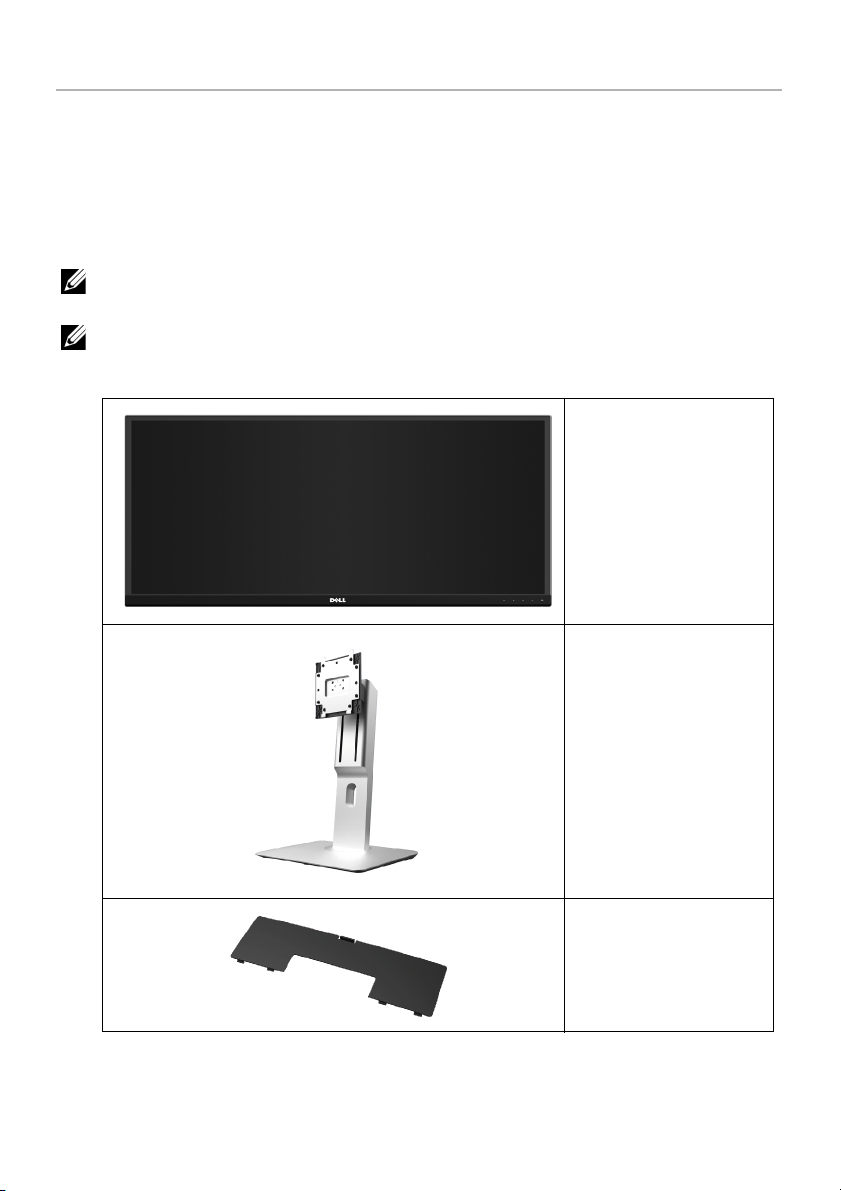
Package Contents
Your monitor ships with the components shown below. Ensure that you have received all
the components and
TE: Some items may be optional and may not ship with your monitor. Some
NO
features or media may not be available in certain countries.
NOTE: To set up with any other stand, please refer to the respective stand setup
guide for setup instructions.
Contact Dell
if something is missing.
Monitor
Stand
Cable Cover
About Your Monitor | 5
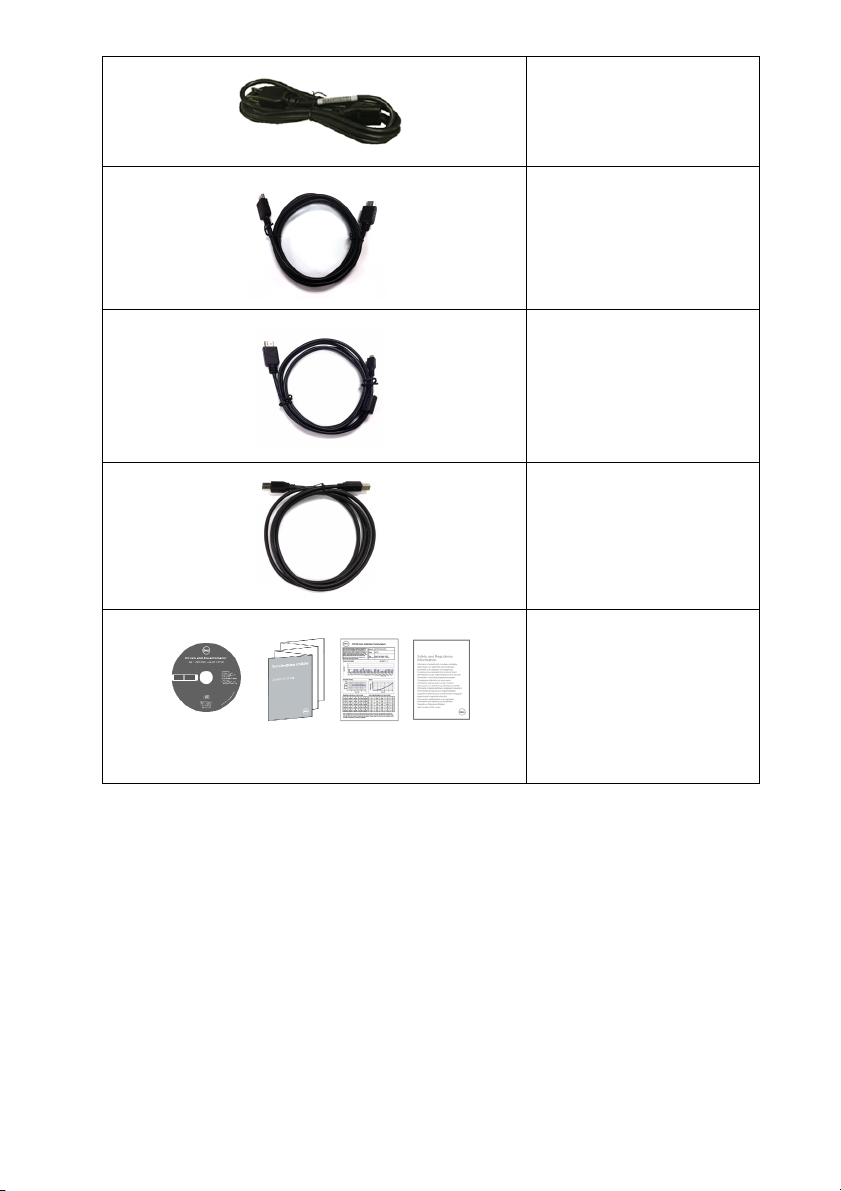
Power Cable (Varies by
Countr
ies)
HDMI Cable
DP Cable (Mini-DP to DP)
USB 3.0 Upstream Cable
(Enables
the Monitor)
• Drivers and
• Quick Setup
• Fa
• S
the USB Ports on
Documentation Media
Guide
ctory Calibration
Report
afety and Regulatory
Information
6 | About Your Monitor

Product Features
The Dell U3415W flat panel display has an active matrix, Thin-Film Transistor (TFT), Liquid
Crystal Display (LCD) and LED backlight. The monitor features include:
• 86.5 cm (34-inch) viewable area display (measured diagonally).
3440 x 1440 resolution, plus full-screen support for lower resolutions.
• Wide viewing angle to allow viewing from a sitting or standing position, or while
moving from side-to-side.
• Tilt, swivel, and vertical extension adjustment capabilities.
• Ultra-thi
set up with an elegant viewing experience.
• Removable stand and Video Electronics Standards Association (VESA™) 100 mm
mounting holes for flexible mounting solutions.
• Extensive all digital connectiv
USB 3.0 helps future proof your monitor.
• Equipped with 2 USB upstream ports and 4 USB downstream ports.
• Plug and
• Color gamut of 99% sRGB with an average Delta E < 3.
• On
• So
Matching File (ICM), and product documentation.
• Dell Display Manager Software included (comes in the CD shipped with the
monitor).
• Energy Saver feature for Energy Star compliance.
• Security loc
• Stand lock.
• Capability
the image quality.
• EP
• U3415W monitor is BFR/PVC-free (Halogen-free) excluding external cables.
• T
• Meets N
• Arsenic-Free glass and Mercury-Free for the panel only.
• H
• 0
• Energy Gauge shows the energy level being consumed by the monitor in real time.
• Suppor
n bezel minimizes the bezel gap in multi-monitor usage, enabling easier
ity with DisplayPort, mini DisplayPort, HDMI 2.0, MHL,
play capability if supported by your system.
-Screen Display (OSD) adjustments for ease of set-up and screen optimization.
ftware and documentation media includes an Information File (INF), Image Color
k slot.
to switch from wide aspect to standard aspect ratio while maintaining
EAT Gold Rating.
CO-Certified Displays.
FPA 99 leakage current requirements.
igh Dynamic Contrast Ratio (2,000,000:1).
.5 W standby power when in the sleep mode.
ts Picture by Picture (PBP) and Picture in Picture (PIP) Select mode.
About Your Monitor | 7
Identifying Parts and Controls
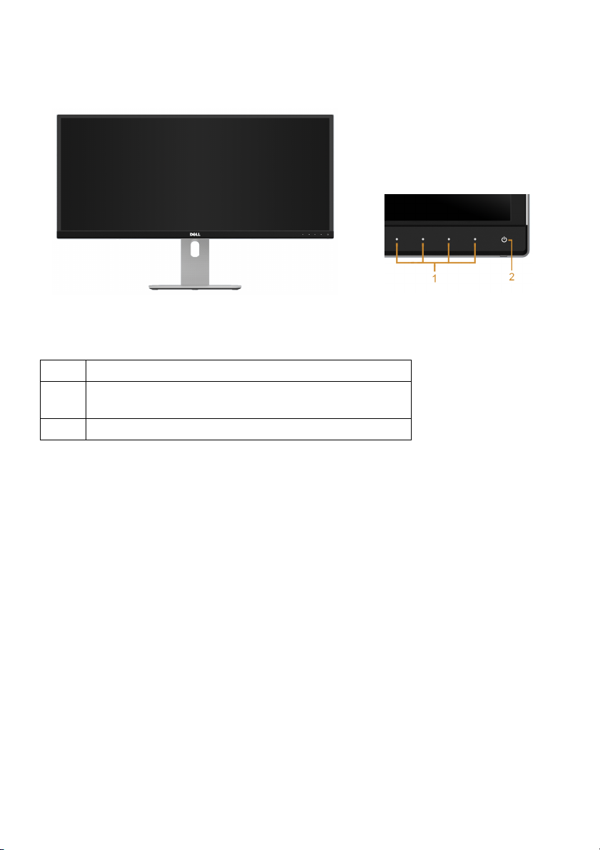
Front View
Label Description
1 Function buttons (For more information, see
Operating the Monitor
2 Power On/Off button (with LED indicator)
)
Front panel controls
8 | About Your Monitor
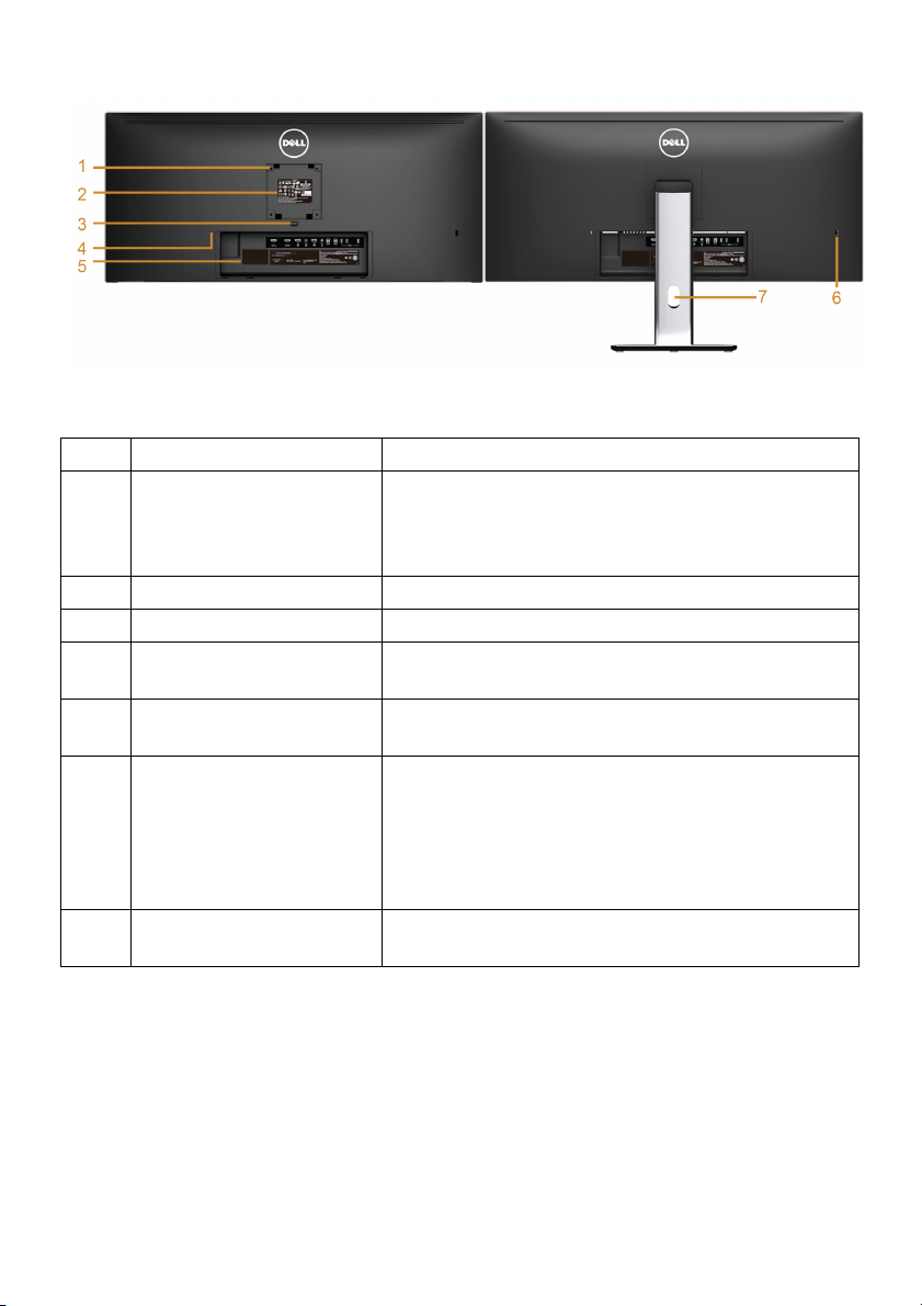
Back View
Back view with monitor stand
Label Description Use
1 VESA mounting holes
100 mm x 100 mm -
(
behind attached VESA
Cover)
2 Regulatory label Lists the regulatory approvals.
3 Stand release button Releases stand from monitor.
4 Security lock slot Secures monitor with security lock (security lock
5 Barcode serial number
l
labe
6 USB downstream port* Connect your USB device to this USB charging
7 Cable management slot Use to organize cables by placing them through
Wall mount monitor using VESA-compatible wall
mount kit (100 mm x 100 mm).
cluded).
not in
Refer to this label if you need to contact Dell for
technical support.
rt, which supports fast current charging
po
capability if the device is BC1.2 compatible. You
can only use this connector after you have
connected the USB cable to the computer and USB
upstream connector on the monitor.
the slot.
* It is recommended to use this port for your wireless USB device whenever possible.
About Your Monitor | 9
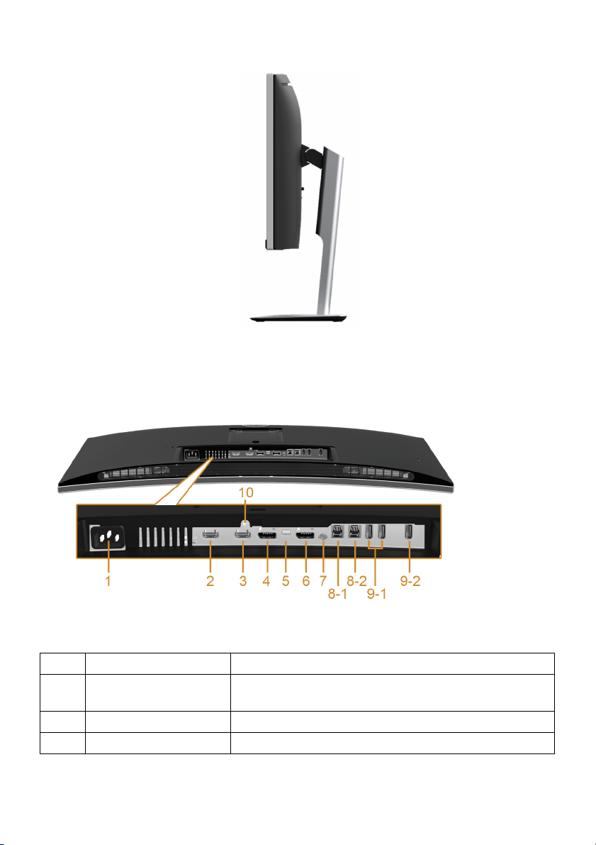
Side View
Bottom View
Bottom view without monitor stand
Label Description Use
1 AC power cord
ector
conn
2 MHL port connector Connect your MHL devices with MHL cable.
3 HDMI port connector Connect your computer with HDMI cable.
Connect the power cable.
10 | About Your Monitor
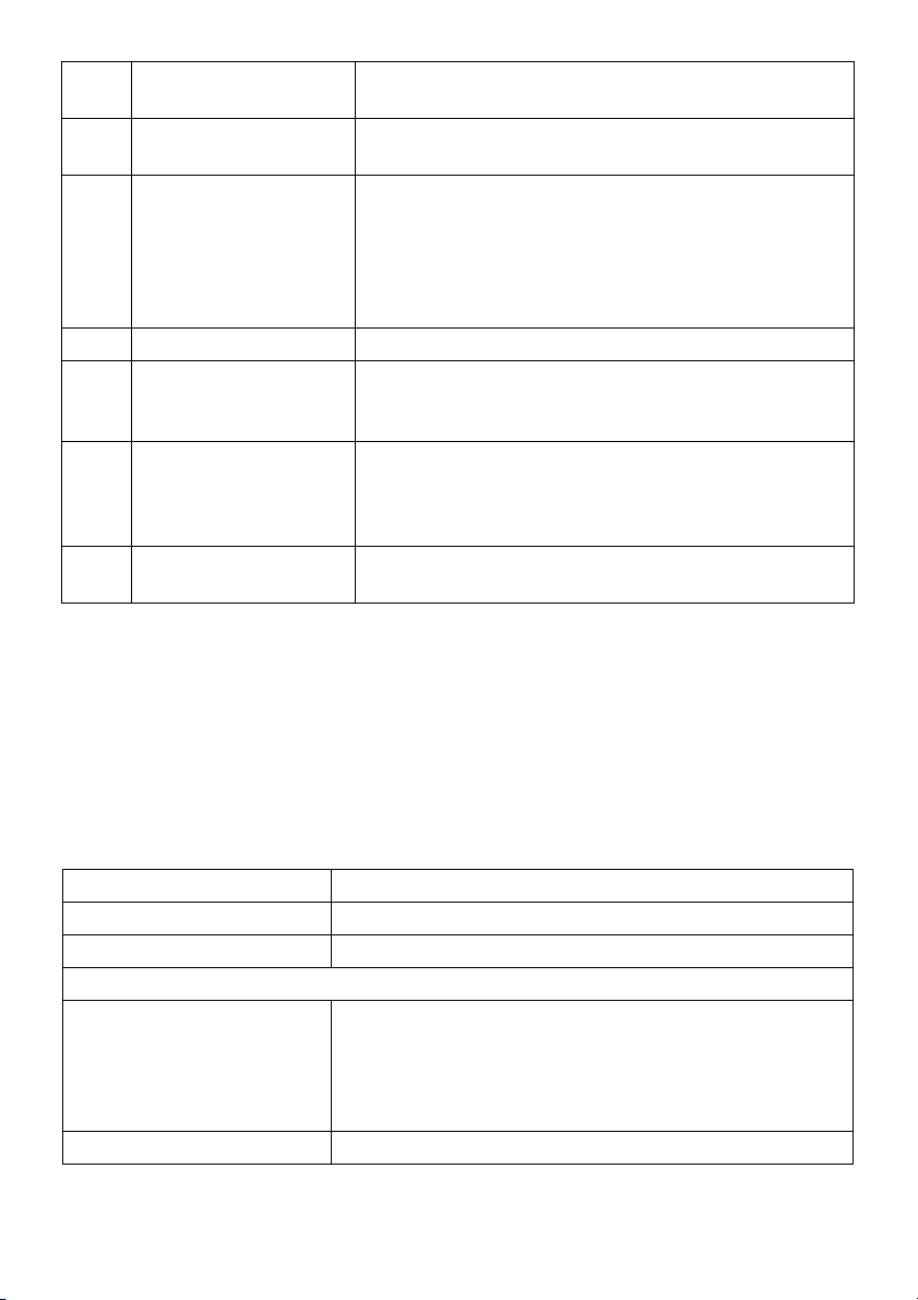
4 DisplayPort in
connector
5 Mini DisplayPort in
ector
conn
6 DisplayPort out (MST)
conn
ector
7 Audio-Line out Connect your speakers.*
USB upstream port Connect the USB cable that came with your monitor
8
, 2)
(1
USB downstream port Connect your USB device. You can only use this
9
, 2)
(1
10 Stand lock feature To lock the stand to the monitor using a M3 x 6 mm
* Headphone usage is not supported for the audio line out connector.
** It is recommended to use either the port (
side for your wireless USB device whenever possible.
Connect your computer with DP cable.
Connect your computer with Mini-DP to DP cable.
DisplayPort output for MST (Multi-Stream Transport)
capable monitor. DP 1.1 monitor can only be
connected as the last monitor in the MST chain. To
enable MST, refer to instruction on section
Connecting the monitor for DP Multi-Stream Transport
"
(MST) function
to the computer. Once this cable is connected, you
can use the USB connectors on the monitor.
connector after you have connected the USB cable to
the computer and USB upstream connector on the
monitor.**
crew (screw not included).
s
".
9-2) or the USB downstream port on the rear
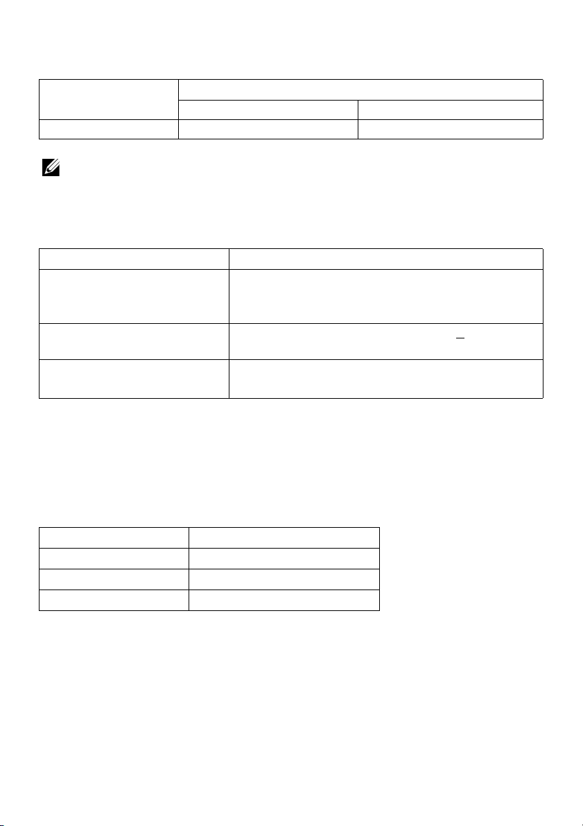
Monitor Specifications
Flat Panel Specifications
Model U3415W
Screen type Active matrix - TFT LCD
Panel type In Plane Switching
Viewable image
Diagonal
Horizontal, Active Area
Vertical, Active Area
Area
Pixel pitch 0.2325 mm x 0.2325 mm
865.56 mm (34.08 inches)
798.20 mm (31.43 inches)
334.80 mm (13.18 inches)
2
267237.36 mm
(414.22 inch2)
About Your Monitor | 11
Viewing angle 178° (vertical) typical
172° (horizontal) typical
Luminance output 300 cd/m² (typical)
Contrast ratio 1000 to 1 (typical)
2M to 1 (typical Dynamic Contrast On)
Faceplate coating Anti-Glare with 3H hardness
Backlight LED edgelight system
Response time 8 ms (typical) for NORMAL mode
5 ms (typical) for FAST mode
Color depth 1.074 billion colors
Color gamut CIE1976 (91%), CIE 1931 (76%
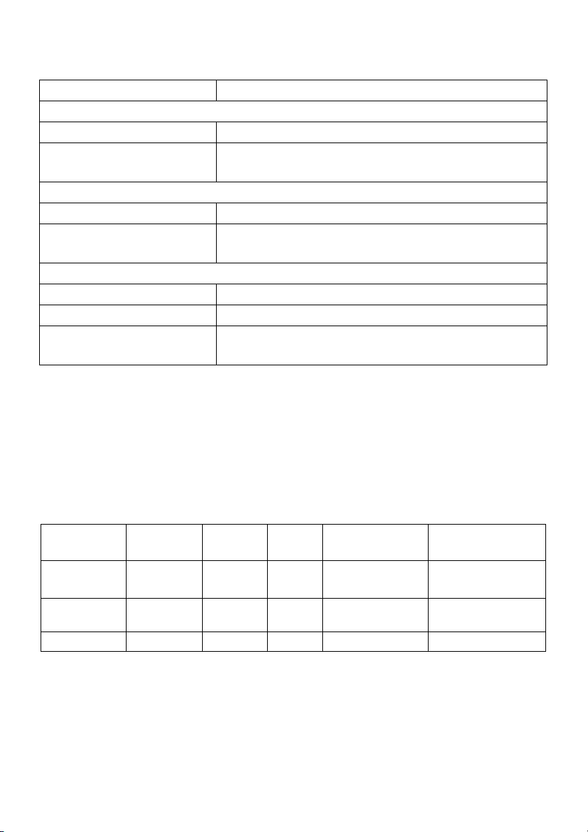
Resolution Specifications
Model U3415W
Horizontal scan range 30 kHz to 89 kHz (automatic)
Vertical scan range 48 Hz to 85 Hz (automatic)
Maximum preset resolution 3440 x 1440 at 60 Hz
Supported Video Modes
), and sRGB coverage 99%
Model U3415W
Video display capabilities
(HDMI & DP
playback)
480p, 480i, 576p, 720p, 1080p, 576i, 1080i
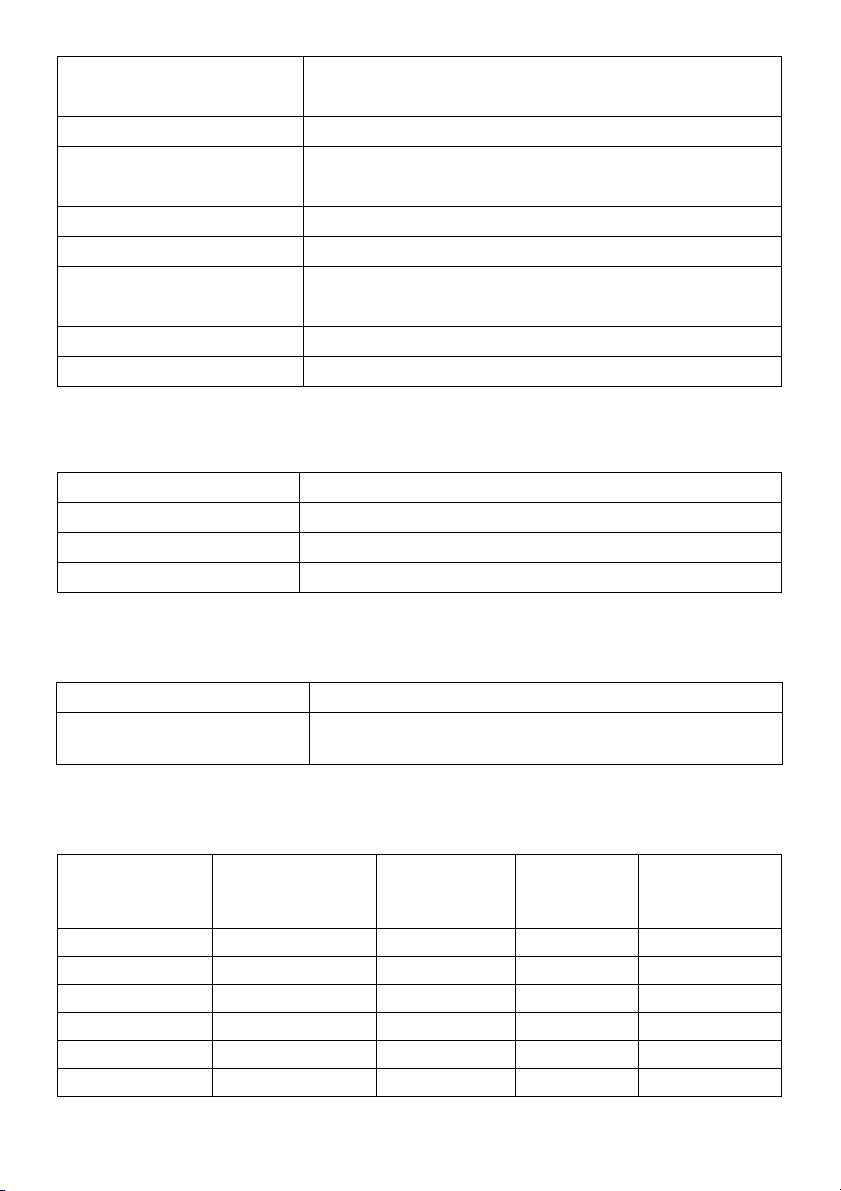
Preset Display Modes
Display Mode Horizontal
equency (kHz)
Fr
VESA, 720 x 400 31.5 70.1 28.3 -/+
VESA, 640 x 480 31.5 60.0 25.2 -/-
VESA, 640 x 480 37.5 75.0 31.5 -/-
VESA, 800 x 600 37.9 60.3 40.0 +/+
VESA, 800 x 600 46.9 75.0 49.5 +/+
VESA, 1024 x 768 48.4 60.0 65.0 -/-
Vertical
Frequency
(Hz)
12 | About Your Monitor
Pixel Clock
(MHz)
Sync Polarity
(Horizontal/
Vertical)
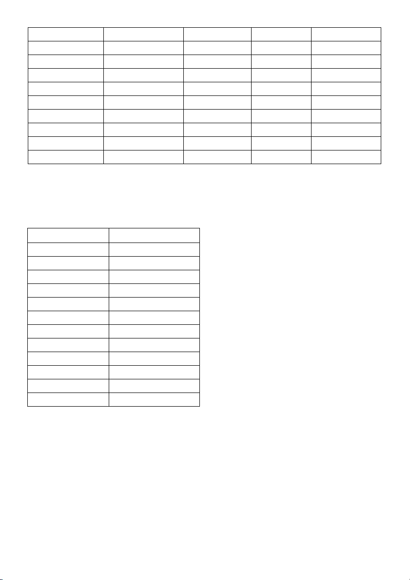
VESA, 1024 x 768 60.0 75.0 78.8 +/+
VESA, 1152 x 864 67.5 75.0 108.0 +/+
VESA, 1280 x 800 49.3 60.0 71.0 +/-
VESA, 1280 x 1024 64.0 60.0 108.0 +/+
VESA, 1280 x 1024 80.0 75.0 135.0 +/+
VESA, 1600 x 1200 75.0 60.0 162.0 +/+
VESA, 1920 x 1080 67.5 60.0 148.5 +/+
VESA, 2560 x 1440 88.8 60.0 241.5 +/-
VESA, 3440 x 1440 73.7 50.0 265.3 +/+
VESA, 3440 x 1440 88.8 60.0* 319.8 +/-
* Requires a graphics card that supports HDMI 2.0.
MHL Source Display Modes
Display Mode Frequency (Hz)
640 x 480p 60
720 x 480p 60
720 x 576p 50
1280 x 720p 60
1280 x 720p 50
1920 x 1080i 60
1920 x 1080i 50
1920 x 1080p 30
1920 x 1080p 60
1920 x 1080p 50
720 (1440) x 480i 60
720 (1440) x 576i 50
About Your Monitor | 13
Multi-Stream Transport (MST) Modes
MST Source
Monitor
3440 x 1440 at 60Hz 1 2
NOTE: Multi-Stream Transport modes are only available with DP1.2. See
Connecting the monitor for DP Multi-Stream Transport (MST) function
Maximum number of external monitor can be supported
3440 x 1440 at 60Hz 1920 x 1080 at 60Hz
for details.
Electrical Specifications
Model U3415W
Video input signals • Digital
• D
AC input voltage/frequency/
current
Inrush current • 120 V
* Support DP1.2 specification, include HBR2, MST and DP audio.
** Not Support HDMI optional specification, include HDMI Ethernet Channel (HEC),
Audio Return Channel (ARC), standard for 3D format and resolutions.
100 VAC to 240 VAC / 50 Hz or 60 Hz
(typical)
• 2
video signal for each differential line. Per
differential line at 100 ohm impedance.
P 1.2*/HDMI 2.0**/MHL 2.0 signal input support
+ 3 Hz / 1.5 A
: 40 A (Max.) at 0 °C (cold start)
40 V: 80 A (Max.) at 0 °C (cold start)
Speaker Specifications
Model U3415W
Speaker 2 x 9.0 W
Frequency Response 100 Hz - 20 kHz
Impedance 8 ohm
14 | About Your Monitor

Physical Characteristics
Model U3415W
Connector type DP, black connector (include DP in and DP
; Mini DisplayPort; HDMI; MHL; USB 3.0
out)
Signal cable type • Digital: detachable, HDMI
• Digital: detachable, MHL, 19 pins
• Digital:
• Univer
Dimensions (with stand)
Height (extended) 523.7 mm (20.62 inches)
Height (compressed) 408.7 mm (16.09 inches)
Width 824.7 mm (32.47 inches)
Depth 216.0 mm (8.50 inches)
Dimensions (without stand)
Height 372 mm (14.65 inches)
Width 824.7 mm (32.47 inches)
Depth 73.3 mm (2.89 inches)
Stand dimensions
Height (extended) 418.0 mm (16.46 inches)
Height (compressed) 370.8 mm (14.60 inches)
Width 245.0 mm (9.65 inches)
Depth 216.0 mm (8.50 inches)
Weight
Weight with packaging 17.50 kg (38.56 lb)
Weight with stand assembly and cables 11.25 kg (24.80 lb)
Weight without stand assembly (For wall
mount or VESA mount consi
no cables)
Weight of stand assembly 2.36 kg (5.20 lb)
Front frame gloss 8%-13% gloss unit
derations -
8.44 kg (18.60 lb)
detachable, Mini-DP to DP, 20
pins
sal Serial Bus: detachable, USB, 9
pins
, 19 pins
About Your Monitor | 15
Environmental Characteristics
Model U3415W
mpe ra tu re
Te
Operating 0 °C to 40 °C (32 °F to 104 °F)
Non-operating • Storage: -20 °C
ipping: -20 °C to 60 °C (-4 °F to 140 °F)
• Sh
to 60 °C (-4 °F to 140 °F)
Humidity
Operating 10% to 80% (non-condensing)
Non-operating • Stor
age: 5% to 90% (non-condensing)
ipping: 5% to 90% (non-condensing)
• Sh
Altitude
Operating 5,000 m (16,404 ft) (maximum)
Non-operating 12,192 m (40,000 ft) (maximum)
Thermal dissipation • 443
.58 BTU/hour (maximum)
• 187.67 BTU/hour (typical)
Power Management Modes
If you have VESA's DPM™ compliance display card or software installed in your PC, the
monitor can automatically reduce its power consumption when not in use. This is
referred to as Power Save Mode*. If the computer detects input from the keyboard,
mouse, or other input devices, the monitor automatically resumes functioning. The
following table shows the power consumption and signaling of this automatic power
saving feature.
VESA Modes Horizontal
Sync
Normal
operation
Active-off
mode
Switch off - - - Off Less than 0.5 W
Active Active Active White 130 W (maximum)**
Inactive Inactive Blanked White (glowing) Less than 0.5 W
* Zero power consumption in OFF mode can only
Vertical
Sync
Video Power
Indicator
be achieved by disconnecting the
Power
Consumption
55 W (typical)
main cable from the monitor.
** Maximum power consumption with max luminan
ce, and USB active.
The OSD functions only in the normal operation mode. When any button is pressed in
the Active-off mode, one of the following messages will be displayed:
16 | About Your Monitor
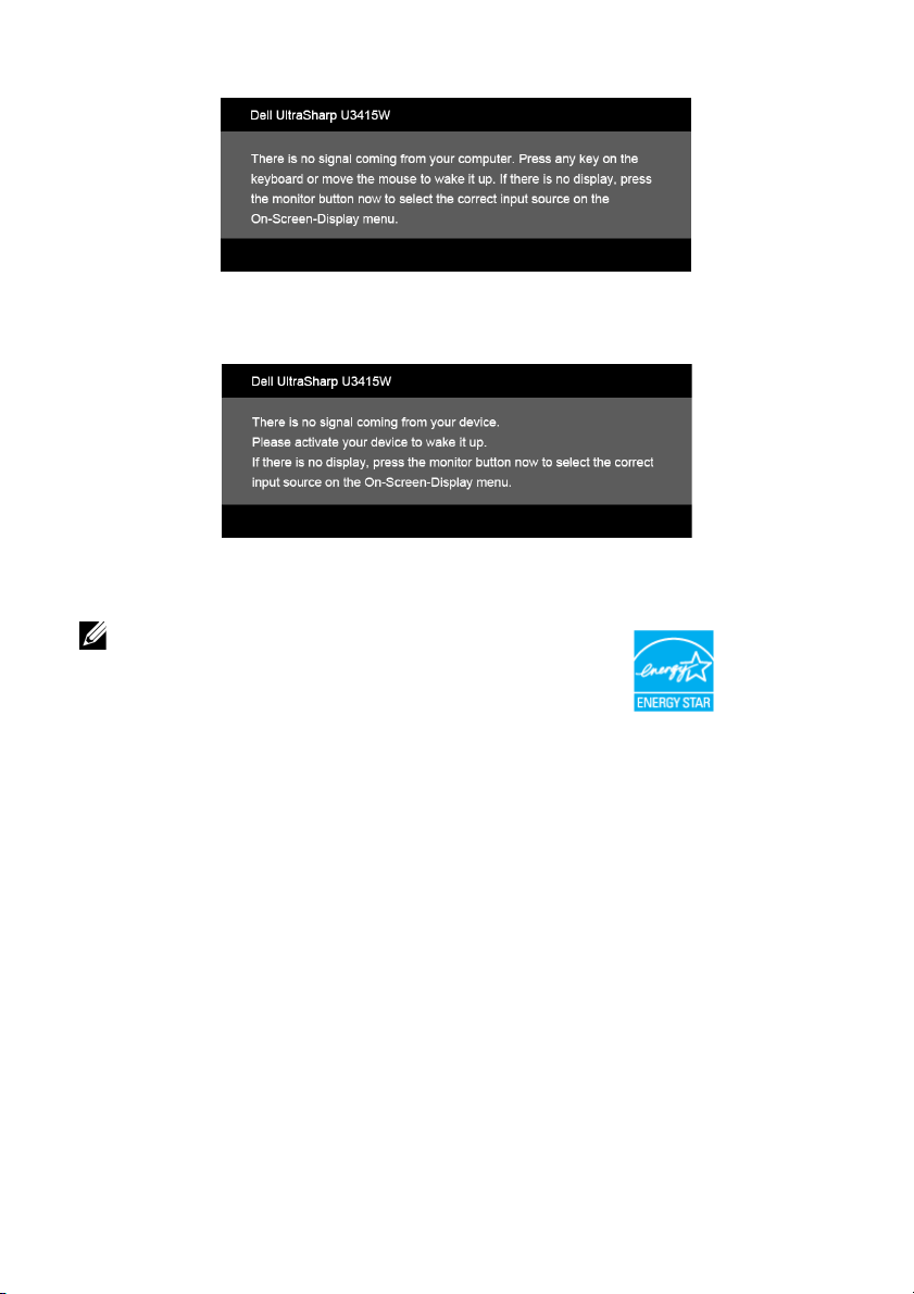
HDMI/MHL/Mini DisplayPort/DP input
HDMI/MHL input
Activate the computer and the monitor to gain access to the OSD.
NOTE: This moni
tor is ENERGY STAR®-compliant.
About Your Monitor | 17
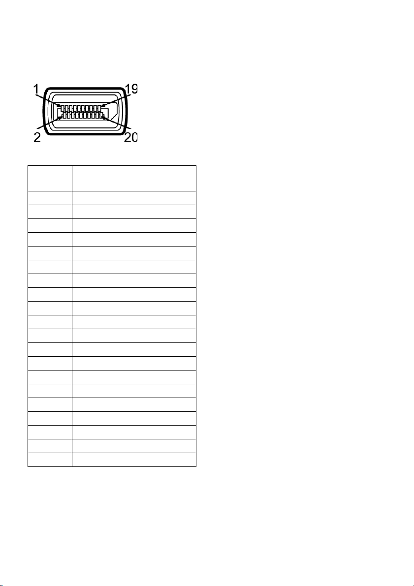
Pin Assignments
DisplayPort Connector
Pin
Number
1 ML0(p)
2 GND
3 ML0(n)
4 ML1(p)
5 GND
6 ML1(n)
7 ML2(p)
8 GND
9 ML2(n)
10 ML3(p)
11 GND
12 ML3(n)
13 GND
14 GND
15 AUX(p)
16 GND
17 AUX(n)
18 GND
19 Re-PWR
20 +3.3 V DP_PWR
20-pin Side of the
Con
nected Signal Cable
18 | About Your Monitor
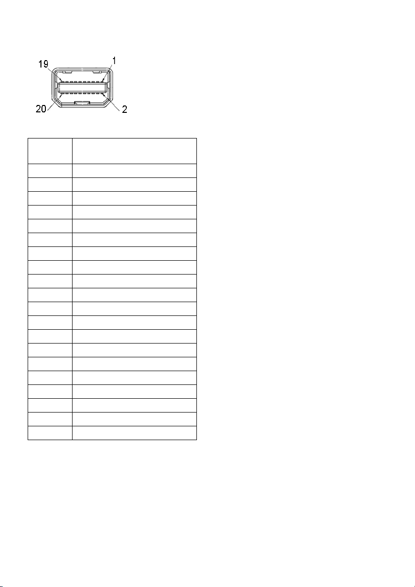
Mini DisplayPort Connector
Pin
Number
1 GND
2 Hot Plug Detect
3 ML3(n)
4 GND
5 ML3(n)
6 GND
7 GND
8 GND
9 ML2(n)
10 ML0(p)
11 ML2(p)
12 ML0(p)
13 GND
14 GND
15 ML1(n)
16 AUX(p)
17 ML1(p)
18 AUX(n)
19 GND
20 +3.3 V DP_PWR
20-pin Side of the
Con
nected Signal Cable
About Your Monitor | 19
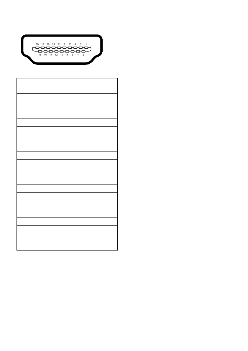
HDMI Connector
Pin
Number
1 TMDS DATA 2+
2 TMDS DATA 2 SHIELD
3 TMDS DATA 2-
4 TMDS DATA 1+
5 TMDS DATA 1 SHIELD
6 TMDS DATA 1-
7 TMDS DATA 0+
8 TMDS DATA 0 SHIELD
9 TMDS DATA 0-
10 TMDS CLOCK+
11 TMDS CLOCK SHIELD
12 TMDS CLOCK-
13 CEC
14 Reserved (N.C. on device)
15 DDC CLOCK (SCL)
16 DDC DATA (SDA)
17 DDC/CEC Ground
18 +5V POWER
19 HOT PLUG DETECT
19-pin Side of the
Con
nected Signal Cable
20 | About Your Monitor

MHL Connector
Pin
Number
1 TMDS DATA 2+
2 TMDS DATA 2 SHIELD
3 TMDS DATA 2-
4 TMDS DATA 1+
5 GND
6 TMDS DATA 1-
7 MHL+
8 TMDS DATA 0 SHIELD
9 MHL-
10 TMDS CLOCK+
11 GND
12 TMDS CLOCK-
13 CEC
14 Reserved (N.C. on device)
15 DDC CLOCK (SCL)
16 DDC DATA (SDA)
17 GND
18 VBUS (+5V, 900mA maximum)
19 CBUS
19-pin Side of the
nected Signal Cable
Con
Plug and Play Capability
You can install the monitor in any Plug and Play-compatible system. The monitor
automatically provides the computer system with its Extended Display Identification Data
(EDID) using Display Data Channel (DDC) protocols so the system can configure itself
and optimize the monitor settings. Most monitor installations are automatic; you can
select different settings if desired. For more information about changing the monitor
settings, see
Operating the Monitor
.
About Your Monitor | 21
 Loading...