

Dell 1800FP INSTALLATION

Norris Parts Repair Manual
Dell 1800FP Power Supply
Installation Instructions
1
Copyright©2006 – All Rights Reserved - Distribution or Dupli cation of this document is prohibited.

Norris Parts Repair Manual
2
The Dell UltraSharp 1800FP was designed for a wide variety of users ranging from the home to
corporate or financial trading environments. It utilizes an 18.1" Active Matrix TFT LCD that displays
brilliant images of text and graphics with a maximum resolution up to 1280 x 1024 pixels.
Common Problems associated with this model:
1. NO POWER.
2. No Indicator lights are green on front panel.
Resolving these issues (Part Replacement):
1. Replace the power supply P/N 6870T445D10.
This Power Supply works on the following models:
BRAND MODEL REMARK
DELL 1800FP 18.1" LCD MONITOR
Disassembly Instructions:
1. Place monitor face down on flat surface using a soft towel to avoid scratching the LCD screen.
2. Use a cup or other small container to hold the screws as they are removed.
3. It is recommended, not required, that you purchase a static wrist guard or other anti-static
guard. These can be purchased at a nominal cost at a computer hardware store or electronics
repair shop.
4. Make sure the unit is unplugged and the power supply/plug is removed from the unit.
5. Important: Do not apply force onto the LCD screen at anytime, this will cause permanent
damage.
6. This manual is provided as a reference guide. If you do not understand disassembly process
or you do not feel that you are competent to perform the repair, then you should have the
repair completed by a professional repair technician.
Disclaimer:
Norris Parts provides this manual for reference only. Norris Parts is not responsible for any actions
taken by the user of this manual. Norris Parts is not responsible for damage resulting from the repair
or use of any equipment referenced in this manual.
Copyright©2006 – All Rights Reserved - Distribution or Dupli cation of this document is prohibited.
Norris Parts Repair Manual
Disassembly
3
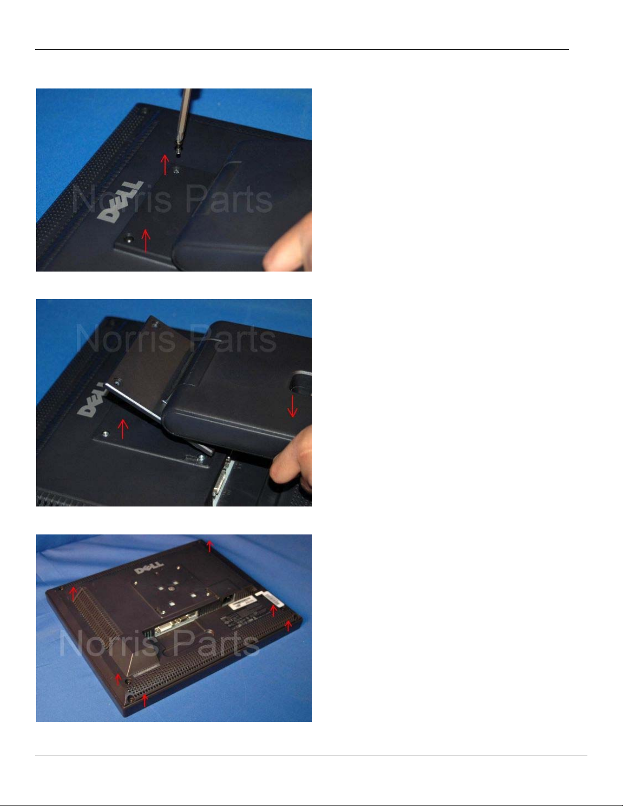
Step 1:
Remove the two (2) screws from the
top of the base.
Step 2:
Remove the base.
Step 3:
Remove the six (6) screws from the
back cover.
Copyright©2006 – All Rights Reserved - Distribution or Dupli cation of this document is prohibited.
 Loading...