

Page 1
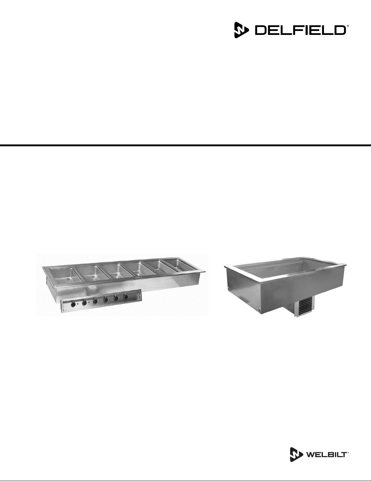
Drop Ins
8100-EF, N8000, N8000N, N8000-R, N8100B,
N8100-BR, N8100-FA, N8200, N8200G, N8200-ST,
N8600, N8700-D, N8700-DESP, N8700-R, N8800
Original Instructions
Service Manual
This manual is updated as new information and models are released. Visit our website for the latest manual.
Part Number: 8000_SM 07/18
Page 2
Safety Notices
Warning
n
Read this manual thoroughly before operating, installing
or performing maintenance on the equipment. Failure
to follow instructions in this manual can cause property
damage, injury or death.
DANGER
Keep power cord AWAY from HEATED surfaces. DO NOT
immerse power cord or plug in water. DO NOT let power
cord hang over edge of table or counter.
DANGER
Do not lift the condensing unit by the refrigerant tubing
or other components. These features will not support
the condensing unit weight. Injury and unit damage
may occur!
DANGER
Do not install or operate equipment that has been
misused, abused, neglected, damaged, or altered/
modified from that of original manufactured
specifications.
DANGER
All utility connections and fixtures must be maintained
in accordance with Local and national codes.
Warning
n
This appliance is not intended for use by persons
(including children) with reduced physical, sensory
or mental capabilities, or lack of experience and
knowledge, unless they have been given supervision
concerning use of the appliance by a person responsible
for their safety. Do not allow children to play with this
appliance.
Warning
n
This product contains chemicals known to the State
of California to cause cancer and/or birth defects or
other reproductive harm. Operation, installation, and
servicing of this product could expose you to airborne
particles of glasswool or ceramic fibers, crystalline
silica, and/or carbon monoxide. Inhalation of airborne
particles of glasswool or ceramic fibers is known to the
State of California to cause cancer. Inhalation of carbon
monoxide is known to the State of California to cause
birth defects or other reproductive harm.
Warning
n
Do not use electrical appliances or accessories other
than those supplied by the manufacturer.
Warning
n
Use caution when handling metal surface edges of all
equipment.
Warning
n
DO NOT touch refrigeration lines inside units; some may
exceed temperatures of 200°F (93.3°C).
Note
Proper installation, care and maintenance are
essential for maximum performance and trouble-free
operation of your equipment. Visit our website www.
mtwkitchencare.com for manual updates, translations,
or contact information for service agents in your area.
Warning
n
Do not store or use gasoline or other flammable vapors
or liquids in the vicinity of this or any other appliance.
Never use flammable oil soaked cloths or combustible
cleaning solutions, for cleaning.
Warning
n
Authorized Service Representatives are obligated to
follow industry standard safety procedures, including,
but not limited to, local/national regulations for
disconnection / lock out / tag out procedures for all
utilities including electric, gas, water and steam.
Page 3

Section 1
General Information
Section 2
Installation
Section 3
Operation
Table of Contents
Model Numbers .................................................................................................................. 5
Serial Number Location ..................................................................................................... 6
Warranty Information ........................................................................................................ 6
Regulatory Certifications ..................................................................................................6
Domestic Models ....................................................................................................................................6
Export Models .........................................................................................................................................6
Location ..............................................................................................................................8
Weight Of Equipment ........................................................................................................8
Dimensions ....................................................................................................................... 10
Clearance Requirements ..................................................................................................11
Cutout Installation Dimensions ......................................................................................12
Curved Drop-In Cutout Details ....................................................................................................... 15
Drop-In Counter Installation ...........................................................................................16
Ice Cooled Drop-In Units .................................................................................................................. 16
Self-Contained Refrigerated Drop-In Units ................................................................................ 17
Forced-Air Refrigerated Drop-In Units ......................................................................................... 19
Self-Contained Combo Hot/Cold Drop-In Units ...................................................................... 21
Hot Food Well Drop-In Units ........................................................................................................... 22
Electrical Service ..............................................................................................................23
Voltage .................................................................................................................................................... 23
Ground Fault Circuit Interrupter .................................................................................................... 23
Electrical Specifications Chart ........................................................................................................ 23
Refrigeration ....................................................................................................................25
Optional Auto Fill Installation .........................................................................................26
Applicable to N8600 & N8800 Models ......................................................................................... 26
Applicable to N8700 Models ........................................................................................................... 27
Product Quality in Cold Pans ...........................................................................................29
8100-EF(N) Series Operation ...........................................................................................30
Temperature Control & Display ...................................................................................................... 30
Changing Display from Fahrenheit to Celsius on ERC112 Control .................................... 31
N8100B, N8100-BR & N8100NB Operation ....................................................................32
N8100-FA Operation ........................................................................................................33
N8200 & N8200-ST Operation .........................................................................................33
Operation N8200G ...........................................................................................................33
8600 Hot/Cold Series Operation .....................................................................................34
N8700-D, N8700N, N8700-R & N8800 Series Operation ...............................................35
N8700-DESP Operation....................................................................................................36
Part Number: 8000_SM 07/18 3
Page 4

Section 4
Maintenance
Cleaning and Sanitizing Procedures ...............................................................................37
General .................................................................................................................................................... 37
Exterior Cleaning ................................................................................................................................. 38
Cleaning the Condenser Coil .......................................................................................................... 38
N8100-FA Series Drain Maintenance ............................................................................................ 38
Section 5
Troubleshooting
Problem -> Cause -> Correction Chart ............................................................................39
Section 6
Refrigeration
R404A
Refrigerant Recovery / Evacuation & Recharging .......................................................... 40
Charging Procedures .......................................................................................................40
System Contamination Clean-up ....................................................................................41
Mild System Contamination Clean-Up Procedure ......................................................... 42
Severe System Contamination Clean-Up Procedure .....................................................42
Filter Driers .......................................................................................................................43
Section 7
Component Check Procedures
Table of Contents (continued)
Mechanical Refrigeration Control ..................................................................................44
Electric/Solid State Refrigeration Control .....................................................................44
Unit Air Flow Design ........................................................................................................44
Section 8
Wiring Diagrams
Drop-In Series 8100-EF & 8100-EFN ...............................................................................45
Export Drop-In Series 8100-EF-E & 8100-EFN-E .............................................................47
Drop-In Series N8100B, N8100NB & N8100-BR .............................................................48
Export Drop-In Series N8100B-E & N8100NB-E .............................................................48
N8100-FA Series Models .................................................................................................49
Drop-In Frost Tops Series N8200 & N8200-ST ................................................................ 50
Drop-In Granite Cold Slabs Series N8200G ....................................................................50
Export Drop-In Frost Tops Series N8200-E ..................................................................... 51
Export Drop-In Granite Cold Slabs Series N8200G-E .....................................................51
N8600 Series ..................................................................................................................... 52
N8700D, N8700DESP, N8700-R & N8700N Series ..........................................................55
8700UM Series Models ....................................................................................................59
N8800 Series Models ....................................................................................................... 60
Section 9
Replacement Procedures
Self-Contained Refrigerated Drop-In Units & Self-Contained Combo Hot/Cold Drop-In
Units ......................................................................................................................................................... 44
Forced-Air Refrigerated Drop-In Units ......................................................................................... 44
Plumbing...........................................................................................................................62
Wiring ................................................................................................................................62
4 Part Number: 8000_SM 07/18
Page 5
Section 1
General Information
Model Numbers
8100-EF Series
LiquiTec® Eutetic Fluid Refrigerated Cold Pans - R404A
8118-EF 8132-EF 8145-EF
8159-EF 8172-EF 8186-EF
8100-EF-E Export Series
LiquiTec® Eutetic Fluid Refrigerated Cold Pans - R404A
8118-EF-E 8132-EF-E 8145-EF-E
8159-EF-E 8172-EF-E 8186-EF-E
8100-EFN Series
LiquiTec® Slim Line Eutetic Fluid Refrigerated Cold Pans -
R404A
8148-EFN 8169-EFN 8191-EFN
8100-EFN-E Export Series
LiquiTec® Slim Line Eutetic Fluid Refrigerated Cold Pans -
R404A
8148-EFN-E 8169-EFN-E 8191-EFN-E
N8000 Series
Ice Cooled Cold Pans
N8018 N8030 N8043
N8056 N8069 N8081
N8000N Series
Narrow Ice Cooled Cold Pans
N8046N N8068N
N8000-R Series
Curved Ice Cooled Cold Pans
N8044-R N8059-R N8076-R
N8094-R
N8100B Series
Self-Contained Mechanically Cooled Pans - R404A
N8118B N8130B N8143B
N8156B N8169B N8181B
N8100B-E Export Series
Self-Contained Mechanically Cooled Pans - R404A
N8118B-E N8130B-E N8143B-E
N8100B-E Export Series
Self-Contained Mechanically Cooled Pans - R134A
N8156B-E N8169B-E
N8100BR Series
Curved Self-Contained Mechanically Cooled Pans - R404A
N8144-BR N8159-BR N8176-BR
N8194-BR
N8100-FA Series
Forced Air Drop-In Mechanically Cooled Cold Pans - R404A
N8131-FA N8144-FA N8157-FA
N8169-FA N8182-FA
N8100NB Series
Self-Contained Mechanically Cooled Pans Narrow Style -
R404A
N8146NB N8168NB
N8100NB-E Export Series
Self-Contained Mechanically Cooled Pans Narrow Style -
R404A
N8146NB-E N8168NB-E
N8200 Series
Self-Contained Frost Tops - R404A
N8231 N8245 N8259
N8273 N8287
N8200-E Export Series
Self-Contained Frost Tops - R404A
N8231-E N8245-E N8259-E
N8273-E N8287-E
N8200G Series
Self-Contained Granite Cold Slabs
N8231G N8245G N8259G
N8273G
N8200G-E Export Series
Self-Contained Granite Cold Slabs - R404A
N8231G-E N8245G-E N8259G-E
N8200-ST Series
Self-Contained Frost Tops - R404A
N8230-ST N8240-ST N8256-ST
N8258-ST N8275-ST
N8600 Series
Self Contained Combination Hot/Cold Food Wells - R404A
N8630 N8643 N8656
N8669 N8681
N8700D Series
Individually Controlled Heated Food Wells
N8717-D N8731-D N8745-D
N8759-D N8773-D N8787-D
N8700D-E Export Series
Individually Controlled Heated Food Wells
N8717-D-E N8731-D-E N8745-D-E
N8759-D-E N8773-D-E N8787-D-E
N8700DESP Series
Individually Controlled Energy Savings Heated Food Wells
N8717-DESP N8731-DESP N8745-DESP
N8759-DESP N8773-DESP N8787-DESP
N8700-D-ESP-E Export Series
Individually Controlled Energy Savings Heated Food Wells
N8717-D-ESP-E N8731-D-ESP-E N8745-D-ESP-E
N8759-D-ESP-E N8773-D-ESP-E N8787-D-ESP-E
N8700N Series
Individually Controlled Heated Narrow Food Wells
N8746ND N8768N N8768ND
N8700-R Series
Curved Individually Controlled Heated Food Wells
N8744-R N8759-R N8776-R
N8794-R
N8800 Series
Single Tank Electric Hot Food Wells
N8831 N8845 N8859
N8873 N8887
N8800-E Export Series
Single Tank Electric Hot Food Wells
N8831-E N8845-E N8859-E
N8873-E N8887-E
Part Number: 8000_SM 07/18 5
Page 6
General Information Section 1
Serial Number Location
Ther serial number is listed on the serial tag. If applicable it
will also list the refrigerant used and the amount of charge.
• The serial tag on self-contained refrigerated units is
located near the condensing unit.
• The serial tag on ice cooled units and remote
refrigerated units is on the outside bottom of the food
well.
• On hot food pans and hot/cold combination pans, the
serial tag is located on the back of the control raceway
or remote panel.
Always have the serial number of your unit available
when calling for parts or service.
Warranty Information
• Register your product for warranty,
• Verify warranty information,
• View and download a copy of your warranty,
at www.delfield.com/warranty
Regulatory Certifications
DOMESTIC MODELS
All domestic models are certified by:
•
All domestic electrical models are certified by:
•
•
Domestic N8700DESP models are also certified by:
• Technical Inspection Association
• European Conformity
EXPORT MODELS
All export models are certified by:
•
• Technical Inspection Association
National Sanitation Foundation (NSF)
Underwriters Laboratories (UL)
Underwriters Laboratories of Canada (cUL)
National Sanitation Foundation (NSF)
• European Conformity
6 Part Number: 8000_SM 07/18
Page 7
Section 2
Installation
DANGER
Installation must comply with all applicable fire and
health codes in your jurisdiction.
DANGER
Use appropriate safety equipment during installation
and servicing.
Warning
n
Remove all removable panels before lifting and
installing.
Warning
n
If a refrigerated base does not have a condensate
evaporator supplied, you must connect the condensate
line to a suitable drain. Otherwise, water will collect on
the floor, causing a potentially hazardous situation.
Warning
n
Moisture collecting from improper drainage can create a
slippery surface on the floor and a hazard to employees.
It is the owner’s responsibility to provide a container or
outlet for drainage.
Warning
n
This equipment is intended for indoor use only. Do not
install or operate this equipment in outdoor areas.
Caution
,
The units with LiquiTec technology cold pans contain a
non-toxic eutectic fluid within a sealed inner liner. This
fluid may leak if the tank is punctured so care must be
taken when uncrating and setting in place. The eutectic
fluid is non-toxic and may be flushed down a disposal
drain. Units with a Eutectic Fluid Cold Pan require the
same precautions. The fluid is NOT refillable and loss of
fluid due to a puncture would cause irreparable damage.
If the LiquiTec unit cold pans leak, immediately call the
Delfield service department directly at 1-800-733-8821
not your local service agent.
Caution
,
Do not position the air intake vent near steam or heat
exhaust of another appliance.
Warning
n
Do not damage the refrigeration circuit when installing,
maintaining or servicing the unit.
Warning
n
This equipment must be positioned so that the plug is
accessible unless other means for disconnection from
the power supply (e.g., circuit breaker or disconnect
switch) is provided.
Warning
n
Adequate means must be provided to limit the
movement of this appliance without depending on or
transmitting stress to the electrical conduit.
Warning
n
To avoid instability the installation area must be capable
of supporting the combined weight of the equipment
and product. Additionally the equipment must be level
side to side and front to back.
Part Number: 8000_SM 07/18 7
Page 8
Installation Section 2
Location
The location selected for the equipment must meet the
following criteria. If any of these criteria are not met, select
another location.
• Units are intended for indoor use only.
• The location MUST be level, stable and capable of
supporting the weight of the equipment.
• The location MUST be free from and clear of
combustible materials.
• Equipment MUST be level both front to back and side to
side.
• Position the equipment so it will not tip or slide.
• Recommended air temperature is 41° - 86°F (5° - 30°C).
• Proper air supply for ventilation is REQUIRED AND
CRITICAL for safe and efficient operation. Refer to
Clearance Requirements chart on page 11.
• Do not obstruct the flow of ventilation air. Make sure the
air vents of the equipment are not blocked.
• Do not install the equipment directly over a drain.
Steam rising up out of the drain will adversely affect
operation, air circulation, and damage electrical /
electronic components.
Weight Of Equipment
Model Ship Weight
8100-EF Series
8118-EF 169lbs (77kg)
8132-EF 215lbs (98kg)
8145-EF 265lbs (120kg)
8159-EF 285lbs (130kg)
8172-EF 295lbs (134kg)
8186-EF 394lbs (179kg)
8100-EF-E Export Series
8118-EF-E 169lbs (77kg)
8132-EF-E 215lbs (98kg)
8145-EF-E 265lbs (120kg)
8159-EF-E 285lbs (130kg)
8172-EF-E 295lbs (134kg)
8186-EF-E 394lbs (179kg)
8100-EFN Series
8148-EFN 235lbs (107kg)
8169-EFN 285lbs (130kg)
8191-EFN 295lbs (134kg)
8100-EFN-E Export Series
8148-EFN-E 235lbs (107kg)
8169-EFN-E 285lbs (130kg)
8191-EFN-E 295lbs (134kg)
N8000 Series
N8018
N8030
N8043
N8056
N8069
N8081
N8000N Series
N8046N 100lbs (45kg)
N8068N 120lbs (55kg)
N8000-R Series
N8044-R 100lbs (45kg)
N8059-R 118lbs (53kg)
N8076-R 145lbs (65kg)
N8094-R 164lbs (74kg)
N8100B Series
N8118B 100lbs (45kg)
N8130B 140lbs (64kg)
N8143B 173lbs (78kg)
N8156B 205lbs (93kg)
N8169B 225lbs (102kg)
N8181B 258lbs (117kg)
N8100B-E Export Series - R404A
N8118B-E 100lbs (45kg)
N8130B-E 140lbs (64kg)
N8143B-E 173lbs (78kg)
N8100B-E Export Series - R134A
N8156B-E 205lbs (93kg)
N8169B-E 225lbs (102kg)
N8100BR Series
N8144-BR 161lbs (72kg)
N8159-BR 184lbs (83kg)
N8176-BR 233lbs (105kg)
N8194-BR 243lbs (109kg)
38lbs (17kg)
84lbs (38kg)
110lbs (50kg)
139lbs (63kg)
160lbs (73kg)
197lbs (89kg)
8 Part Number: 8000_SM 07/18
Page 9
Section 2 Installation
Model Ship Weight
N8100-FA Series
N8131-FA 168lbs (76kg)
N8144-FA 175lbs (79kg)
N8157-FA 225lbs (102kg)
N8169-FA 235lbs (107kg)
N8182-FA 406lbs (184kg)
N8100NB Series
N8146NB 175lbs (80kg)
N8168NB 240lbs (109kg)
N8100NB-E Export Series
N8146NB-E 175lbs (80kg)
N8168NB-E 240lbs (109kg)
N8200 Series
N8231 142lbs (64kg)
N8245 168lbs (76kg)
N8259 193lbs (88kg)
N8273 209lbs (95kg)
N8287 239lbs (108kg)
N8200-E Export Series
N8231-E 142lbs (64kg)
N8245-E 168lbs (76kg)
N8259-E 193lbs (88kg)
N8273-E 209lbs (95kg)
N8287-E 239lbs (108kg)
N8200G Series
N8231G 219lbs (99kg)
N8245G 284lbs (129kg)
N8259G 338lbs (153kg)
N8273G 425lbs (193kg)
N8200G-E Export Series
N8231G-E 219lbs (99kg)
N8245G-E 284lbs (129kg)
N8259G-E 338lbs (153kg)
N8200-ST Series
N8230-ST 142lbs (64kg)
N8240-ST 168lbs (76kg)
N8256-ST 193lbs (88kg)
N8258-ST 209lbs (95kg)
N8275-ST 239lbs (108kg)
N8600 Series
N8630 164lbs (74kg)
N8643 198lbs (90kg)
N8656 233lbs (106kg)
N8669 266lbs (121kg)
N8681 301lbs (137kg)
N8700D Series
N8717-D 41lbs (19kg)
N8731-D 99lbs (45kg)
N8745-D 134lbs (61kg)
N8759-D 166lbs (75kg)
N8773-D 186lbs (84kg)
N8787-D 236lbs (107kg)
N8700D-E Export Series
N8717-D-E 41lbs (19kg)
N8731-D-E 99lbs (45kg)
N8745-D-E 134lbs (61kg)
N8759-D-E 166lbs (75kg)
N8773-D-E 186lbs (84kg)
N8787-D-E 236lbs (107kg)
Model Ship Weight
N8700DESP Series
N8717-DESP 41lbs (19kg)
N8731-DESP 99lbs (45kg)
N8745-DESP 134lbs (61kg)
N8759-DESP 166lbs (75kg)
N8773-DESP 186lbs (84kg)
N8787-DESP 236lbs (107kg)
N8700-D-ESP-E Export Series
N8717-D-ESP-E 41lbs (19kg)
N8731-D-ESP-E 99lbs (45kg)
N8745-D-ESP-E 134lbs (61kg)
N8759-D-ESP-E 166lbs (75kg)
N8773-D-ESP-E 186lbs (84kg)
N8787-D-ESP-E 236lbs (107kg)
N8700N Series
N8746ND 100lbs (45kg)
N8768N 130lbs (59kg)
N8768ND 130lbs (59kg)
N8700-R Series
N8744-R 99lbs (45kg)
N8759-R 134lbs (61kg)
N8776-R 166lbs (75kg)
N8794-R 186lbs (84kg)
N8800 Series
N8831 100lbs (45kg)
N8845 136lbs (62kg)
N8859 158lbs (72kg)
N8873 195lbs (88kg)
N8887 224lbs (102kg)
N8800-E Export Series
N8831-E 100lbs (45kg)
N8845-E 136lbs (62kg)
N8859-E 158lbs (72kg)
N8873-E 195lbs (88kg)
N8887-E 224lbs (102kg)
Part Number: 8000_SM 07/18 9
Page 10
Installation Section 2
Dimensions
Model 12x20
Pans
8118-EF 1 18.20” (46cm)
8132-EF 2 31.76” (81cm)
8145-EF 3 45.32” (115cm)
8159-EF 4 58.88” (150cm)
8172-EF 5 72.44” (184cm)
8186-EF 6 86” (218cm)
8100-EF-E Export Series
8118-EF-E 1 18.20” (46cm)
8132-EF-E 2 31.76” (81cm)
8145-EF-E 3 45.32” (115cm)
8159-EF-E 4 58.88” (150cm)
8172-EF-E 5 72.44” (184cm)
8186-EF-E 6 86” (218cm)
8148-EFN 2 47.66” (121cm)
8169-EFN 3 69.22” (176cm)
8191-EFN 4 90.78” (231cm)
8100-EFN-E Export Series
8148-EFN-E 2 47.66” (121cm)
8169-EFN-E 3 69.22” (176cm)
8191-EFN-E 4 90.78” (231cm)
N8018 1 18“ (46cm)
N8030 2 30.75“ (78cm)
N8043 3 43.5“ (110cm)
N8056 4 56.25“ (143cm)
N8069 5 69“ (175cm)
N8081 6 81.75“ (208cm)
N8046N 2 46.75“ (119cm) 18“
N8068N 3 67.5“ (171cm)
N8044-R 2 40.48” (103cm)
N8059-R 3 57.22” (145cm)
N8076-R 4 73.68” (187cm)
N8094-R 5 89.89” (228cm)
N8118B 1 18” (46cm)
N8130B 2 30.75” (78cm)
N8143B 3 43.5” (110cm)
N8156B 4 56.25” (143cm)
N8169B 5 69” (175cm)
N8181B 6 81.75” (208cm)
N8100B-E Export Series - R404A
N8118B-E 1 18” (46cm)
N8130B-E 2 30.75” (78cm)
N8143B-E 3 43.5” (110cm)
N8100B-E Export Series - R134A
N8156B-E 4 56.25” (143cm) 26”
N8169B-E 5 69” (175cm)
N8144-BR 2 40.43” (103cm)
N8159-BR 3 57.22” (145cm)
N8176-BR 4 73.68” (187cm)
N8194-BR 5 89.86” (228cm)
Length Depth Height
8100-EF Series
8100-EFN Series
N8000 Series
N8000N Series
N8000-R Series
N8100B Series
N8100BR Series
26”
(66cm)
26”
(66cm)
18”
(46cm)
18”
(46cm)
26”
(66cm)
(46cm)
26.05”
(66cm)
26”
(66cm)
26”
(66cm)
(66cm)
26.05”
(66cm)
23.25”
(59cm)
23.25”
(59cm)
23.25”
(59cm)
23.25”
(59cm)
10.75”
(27cm)
10.75“
(27cm)
10.77”
(27cm)
21.87”
(56cm)
21.87”
(56cm)
21.87”
(56cm)
21.81”
(55cm)
Model 12x20
Pans
N8131-FA 2 31.25” (79cm)
N8144-FA 3 44” (112cm)
N8157-FA 4 56.75” (144cm)
N8169-FA 5 69.5” (177cm) 26.67”
N8182-FA 6 82.25” (209cm)
N8146NB 2 46.75” (119cm) 18”
N8168NB 3 67.5” (171cm)
N8100NB-E Export Series
N8146NB-E 2 46.75” (119cm) 18”
N8168NB-E 3 67.5” (171cm)
N8231 NA 31.75" (81cm)
N8245 NA 45.63” (116cm)
N8259 NA 59.5” (151cm)
N8273 NA 73.38" (186cm)
N8287 NA 87.25” (222cm)
N8200-E Export Series
N8231-E NA 31.75" (81cm)
N8245-E NA 45.63” (116cm)
N8259-E NA 59.5” (151cm)
N8273-E NA 73.38" (186cm)
N8287-E NA 87.25” (222cm)
N8231G NA 31.75” (81cm)
N8245G NA 45.63” (116cm)
N8259G NA 59.5” (151cm)
N8273G NA 73.38” (186cm)
N8200G-E Export Series
N8231G-E NA 31.75” (81cm)
N8245G-E NA 45.63” (116cm)
N8259G-E NA 59.5” (151cm)
N8230-ST NA 29.60" (75cm) 22”
N8240-ST NA 39.70” (101cm) 29.60”
N8256-ST NA 55.60” (141cm) 22”
N8258-ST NA 57.60" (146cm) 29.60”
N8275-ST NA 75.50" (192cm)
N8630 2 30.75” (78cm)
N8643 3 43.5” (110cm)
N8656 4 56.25” (143cm)
N8669 5 69” (175cm)
N8681 6 81.75” (208cm)
N8717-D 1 17.88” (45cm)
N8731-D 2 31.75” (81cm)
N8745-D 3 45.63” (116cm)
N8759-D 4 59.5” (151cm)
N8773-D 5 73.38” (186cm)
N8787-D 6 87.25” (222cm)
*14” Overall height including drain connection
Length Depth Height
N8100-FA Series
26.67”
(68cm)
(68cm)
N8100NB Series
(46cm)
(46cm)
N8200 Series
26”
(66cm)
26”
(66cm)
N8200G Series
25.87”
(66cm)
25.87”
(66cm)
N8200-ST Series
(56cm)
(75cm)
(56cm)
(75cm)
N8600 Series
26”
(66cm)
N8700D Series
26”
(66cm)
26.62”
(68cm)
28.62”
(73cm)
21.81”
(55cm)
21.81”
(55cm)
15.75”
(40cm)
15.75”
(40cm)
19”
(48cm)
19”
(48cm)
15.70”
(40cm)
23.75”
(60cm)
9.09”
(23cm)*
10 Part Number: 8000_SM 07/18
Page 11
Section 2 Installation
Model 12x20
Pans
N8700D-E Export Series
N8717-D-E 1 17.88” (45cm)
N8731-D-E 2 31.75” (81cm)
N8745-D-E 3 45.63” (116cm)
N8759-D-E 4 59.5” (151cm)
N8773-D-E 5 73.38” (186cm)
N8787-D-E 6 87.25” (222cm)
*14” Overall height including drain connection
N8717-DESP 1 17.89” (45cm)
N8731-DESP 2 31.76” (81cm)
N8745-DESP 3 45.63” (116cm)
N8759-DESP 4 59.50” (151cm)
N8773-DESP 5 73.37” (186cm)
N8787-DESP 6 87.24” (222cm)
*14” Overall height including drain connection
N8700-D-ESP-E Export Series
N8717-D-ESP-E 1 17.89” (45cm)
N8731-D-ESP-E 2 31.76” (81cm)
N8745-D-ESP-E 3 45.63” (116cm)
N8759-D-ESP-E 4 59.50” (151cm)
N8773-D-ESP-E 5 73.37” (186cm)
N8787-D-ESP-E 6 87.24” (222cm)
*14” Overall height including drain connection
N8746ND 2 45.61” (116cm)
N8768N 3 67.48” (172cm)
N8768ND 3 67.48” (172cm)
*14” Overall height including drain connection
N8744-R 2 40.48” (103cm) 26.05”
N8759-R 3 57.22” (145cm) 26.05”
N8776-R 4 73.68” (187cm) 26”
N8794-R 5 89.80” (228cm) 25.91”
*14” Overall height including drain connection
N8831 2 31.75” (81cm)
N8845 3 45.63” (116cm)
N8859 4 59.5” (151cm)
N8873 5 73.38” (186cm)
N8887 6 87.25” (222cm)
N8800-E Export Series
N8831-E 2 31.75” (81cm)
N8845-E 3 45.63” (116cm)
N8859-E 4 59.5” (151cm)
N8873-E 5 73.38” (186cm)
N8887-E 6 87.25” (222cm)
Length Depth Height
N8700DESP Series
N8700N Series
N8700-R Series
N8800 Series
26”
(66cm)
26”
(66cm)
26”
(66cm)
15.87”
(40cm)
(66cm)
(66cm)
(66cm)
(66cm)
26”
(66cm)
26”
(66cm)
9.09”
(23cm)*
7.83”
(20cm)*
7.83”
(20cm)*
9.09”
(23cm)*
9.09”
(23cm)*
11”
(28cm)
11”
(28cm)
Clearance Requirements
DANGER
Minimum clearance requirements are the same for
noncombustible locations as for combustible locations.
The flooring under the appliance must be made of a
noncombustible material.
DANGER
Risk of fire/shock. All minimum clearances must be
maintained. Do not obstruct vents or openings.
Heated & Combination Hot/Cold Food Wells
Bottom & Side Clearance
3” (76mm)
Cooled Pans, Frost Tops & Granite Cold Slabs
Clearance
0” (0cm)
• Keep the vents clean and free of obstruction.
Part Number: 8000_SM 07/18 11
Page 12
Installation Section 2
Cutout Installation Dimensions
Model Counter Cutout
Dimensions
8100-EF Series
8118-EF 17” x 25”
(43cm x 64cm)
8132-EF 30.75” x 25”
(78cm x 64cm)
8145-EF 44.25” x 25”
(112cm x 64cm)
8159-EF 57.87” x 25”
(147cm x 64cm)
8172-EF 71.5” x 25”
(182cm x 64cm)
8186-EF 85” x 25”
(216cm x 64cm)
8100-EF-E Export Series
8118-EF-E 17” x 25”
(43cm x 64cm)
8132-EF-E 30.75” x 25”
(78cm x 64cm)
8145-EF-E 44.25” x 25”
(112cm x 64cm)
8159-EF-E 57.87” x 25”
(147cm x 64cm)
8172-EF-E 71.5” x 25”
(182cm x 64cm)
8186-EF-E 85” x 25”
(216cm x 64cm)
8100-EFN Series
8148-EFN 46.88” x 17.25”
(119cm x 44cm)
8169-EFN 68.5” x 17.25”
(174cm x 44cm)
8191-EFN 90” x 17.25”
(229cm x 44cm)
8100-EFN-E Export Series
8148-EFN-E 46.88” x 17.25”
(119cm x 44cm)
8169-EFN-E 68.5” x 17.25”
(174cm x 44cm)
8191-EFN-E 90” x 17.25”
(229cm x 44cm)
N8000 Series
N8018
N8030
N8043
N8056
N8069
N8081
17” x 25”
(43cm x 64cm)
29.75” x 25”
(76cm x 64cm)
42.5” x 25”
(108cm x 64cm)
55.25” x 25”
(140cm x 64cm)
68” x 25”
(173cm x 64cm)
80.75” x 25”
(205cm x 64cm)
Control Panel Cutout
Dimensions
NA
NA
NA
NA
NA
Model Counter Cutout
Dimensions
N8000N Series
N8046N
N8068N
N8044-R
N8059-R
N8076-R
N8094-R
N8118B 17” X 25”
N8130B 29.75” x 25”
N8143B 42.50” X 25”
N8156B 55.25” x 25”
N8169B 68” X 25”
N8181B 80.75” x 25”
N8118B-E 17” X 25”
N8130B-E 29.75” x 25”
N8143B-E 42.50” X 25”
N8156B-E 55.25” x 25”
N8169B-E 68” X 25”
N8144-BR
N8159-BR
N8176-BR
N8194-BR
N8131-FA 30.25” x 25.5”
N8144-FA 43” x 25.5”
N8157-FA 55.75” x 25.5”
N8169-FA 68.5” x 25.5”
N8182-FA 81.25” x 25.5”
N8146NB 45.75” x 17”
N8168NB 66.5” x 17”
45.75” x 17”
(116cm x 43cm)
66.50” x 17”
(169cm x 43cm)
N8000-R Series
See drawing on
page 15
N8100B Series
(43cm x 64cm)
(76cm x 64cm)
(108cm x 64cm)
(140cm x 64cm)
(173cm x 64cm)
(205cm x 64cm)
N8100B-E Export Series - R404A
(43cm x 64cm)
(76cm x 64cm)
(108cm x 64cm)
N8100B-E Export Series - R134A
(140cm x 64cm)
(173cm x 64cm)
N8100BR Series
See drawing on
page 15
N8100-FA Series
(77cm x 65cm)
109cm x 65cm)
(142cm x 65cm)
174cm x 65cm)
(206cm x 65cm)
N8100NB Series
(116cm x 43cm)
(169cm x 43cm)
Control Panel Cutout
Dimensions
NA
NA
NA
NA
NA
NA
NA
NA
12 Part Number: 8000_SM 07/18
Page 13
Section 2 Installation
Model Counter Cutout
Dimensions
N8100NB-E Export Series
N8146NB-E 45.75” x 17”
(116cm x 43cm)
N8168NB-E 66.5” x 17”
(169cm x 43cm)
N8200 Series
N8231 30.75” x 25"
(78cm x 64cm)
N8245 44.63” x 25”
(113cm x 64cm)
N8259 58.50” x 25”
(149cm x 64cm)
N8273 72.38” x 25”
(184cm x 64cm)
N8287 86.25” x 25”
(219cm x 64cm)
N8200-E Export Series
N8231-E 30.75” x 25"
(78cm x 64cm)
N8245-E 44.63” x 25”
(113cm x 64cm)
N8259-E 58.50” x 25”
(149cm x 64cm)
N8273-E 72.38” x 25”
(184cm x 64cm)
N8287-E 86.25” x 25”
(219cm x 64cm)
N8200G Series
N8231G 30.75” X 25”
(78cm x 64cm)
N8245G 44.63” x 25”
(113cm x 64cm)
N8259G 58.5” x 25”
(149cm x 64cm)
N8273G 72.38” x 25”
(184cm x 64cm)
N8200G-E Export Series
N8231G-E 30.75” X 25”
(78cm x 64cm)
N8245G-E 44.63” x 25”
(113cm x 64cm)
N8259G-E 58.5” x 25”
(149cm x 64cm)
N8200-ST Series
N8230-ST 28.60” x 21.10"
(73cm x 54cm)
N8240-ST 38.65” x 28.75”
(98cm x 73cm)
N8256-ST 54.60” x 21.10”
(139cm x 54cm)
N8258-ST 56.60” x 28.75”
(144cm x 73cm)
N8275-ST 74.50" x 28.75"
(189cm x 73cm)
Control Panel Cutout
Dimensions
NA
NA
NA
NA
NA
NA
Model Counter Cutout
Dimensions
N8600 Series
N8630 29.75” X 25”
(76cm x 64cm)
N8643 42.50” x 25”
(108cm x 64cm)
N8656 55.25” x 25”
(140cm x 64cm)
N8669 68” x 25”
(173cm x 64cm)
N8681 80.75” x 25”
(205cm x 64cm)
N8700D Series
N8717-D 16.88” X 25”
(43cm x 64cm)
N8731-D 30.75” x 25”
(78cm x 64cm)
N8745-D 44.62” x 25”
(113cm x 64cm)
N8759-D 58.5” x 25”
(149cm x 64cm)
N8773-D 72.37” x 25”
(184cm x 64cm)
N8787-D 86.25” x 25”
(219cm x 64cm)
N8700D-E Export Series
N8717-D-E 16.88” X 25”
(43cm x 64cm)
N8731-D-E 30.75” x 25”
(78cm x 64cm)
N8745-D-E 44.62” x 25”
(113cm x 64cm)
N8759-D-E 58.5” x 25”
(149cm x 64cm)
N8773-D-E 72.37” x 25”
(184cm x 64cm)
N8787-D-E 86.25” x 25”
(219cm x 64cm)
N8700DESP Series
N8717-DESP 16.87” X 25”
(43cm x 64cm)
N8731-DESP 30.75” x 25”
(78cm x 64cm)
N8745-DESP 44.62” x 25”
(113cm x 64cm)
N8759-DESP 58.50” x 25”
(149cm x 64cm)
N8773-DESP 72.37” x 25”
(184cm x 64cm)
N8787-DESP 86.25” x 25”
(219cm x 64cm)
Control Panel Cutout
Dimensions
12.25” x 4.25” x 7”
(31cm x 11cm x 18cm)
7” x 4.62” x 7”
(18cm x 12cm x 18cm)
10.31” x 4.62” x 7”
(26cm x 12cm x 18cm)
14.5” x 4.62” x 7”
(37cm x 12cm x 18cm)
18.69” x 4.62” x 7”
(47cm x 12cm x 18cm)
22.88” x 4.62” x 7”
(58cm x 12cm x 18cm)
27” x 4.62” x 7”
(69cm x 12cm x 18cm)
7” x 4.62” x 7”
(18cm x 12cm x 18cm)
10.31” x 4.62” x 7”
(26cm x 12cm x 18cm)
14.5” x 4.62” x 7”
(37cm x 12cm x 18cm)
18.69” x 4.62” x 7”
(47cm x 12cm x 18cm)
22.88” x 4.62” x 7”
(58cm x 12cm x 18cm)
27” x 4.62” x 7”
(69cm x 12cm x 18cm)
5” x 6.88” x 7.50”
(13cm x 17cm x 19cm)
5” x 11.88” x 7.50”
(13cm x 30cm x 19cm)
5” x 17.38” x 7.50”
(13cm x 44cm x 19cm)
5” x 22.88” x 7.50”
(13cm x 58cm x 19cm)
5” x 28.38” x 7.50”
(13cm x 72cm x 19cm)
5” x 33.88”x 7.50”
(13cm x 86cm x 19cm)
Part Number: 8000_SM 07/18 13
Page 14
Installation Section 2
Model Counter Cutout
Dimensions
N8700-D-ESP-E Export Series
N8717-D-ESP-E 16.87” X 25”
(43cm x 64cm)
N8731-D-ESP-E 30.75” x 25”
(78cm x 64cm)
N8745-D-ESP-E 44.62” x 25”
(113cm x 64cm)
N8759-D-ESP-E 58.50” x 25”
(149cm x 64cm)
N8773-D-ESP-E 72.37” x 25”
(184cm x 64cm)
N8787-D-ESP-E 86.25” x 25”
(219cm x 64cm)
N8700N Series
N8746ND 44.62” x 15.0”
(113cm x 38cm)
N8768N 66.50” x 15.0”
(169cm x 38cm)
N8768ND 66.50” x 15.0”
(169cm x 38cm)
N8700-R Series
N8744-R See drawing on
page 15
N8759-R See drawing on
page 15
N8776-R See drawing on
page 15
N8794-R See drawing on
page 15
N8800 Series
N8831 30.75” X 25”
(78cm x 64cm)
N8845 44.63” x 25”
(113cm x 64cm)
N8859 58.5” x 25”
(149cm x 64cm)
N8873 72.38” x 25”
(184cm x 64cm)
N8887 86.25” x 25”
(219cm x 64cm)
N8800-E Export Series
N8831-E 30.75” X 25”
(78cm x 64cm)
N8845-E 44.63” x 25”
(113cm x 64cm)
N8859-E 58.5” x 25”
(149cm x 64cm)
N8873-E 72.38” x 25”
(184cm x 64cm)
N8887-E 86.25” x 25”
(219cm x 64cm)
Control Panel Cutout
Dimensions
5” x 6.88” x 7.50”
(13cm x 17cm x 19cm)
5” x 11.88” x 7.50”
(13cm x 30cm x 19cm)
5” x 17.38” x 7.50”
(13cm x 44cm x 19cm)
5” x 22.88” x 7.50”
(13cm x 58cm x 19cm)
5” x 28.38” x 7.50”
(13cm x 72cm x 19cm)
5” x 33.88”x 7.50”
(13cm x 86cm x 19cm)
10.31” x 4.62” x 7”
(26cm x 12cm x 18cm)
14.50” x 4.62” x 7”
(37cm x 12cm x 18cm)
14.50” x 4.62” x 7”
(37cm x 12cm x 18cm)
10.31” x 4.62” x 7”
(26cm x 12cm x 18cm)
14.5” x 4.62” x 7”
(37cm x 12cm x 18cm)
18.69” x 4.62” x 7”
(47cm x 12cm x 18cm)
22.88” x 4.62” x 7”
(58cm x 12cm x 18cm)
12.25” x 4.25” x 7”
(31cm x 11cm x 18cm)
12.25” x 4.25” x 7”
(31cm x 11cm x 18cm)
14 Part Number: 8000_SM 07/18
Page 15
Section 2 Installation
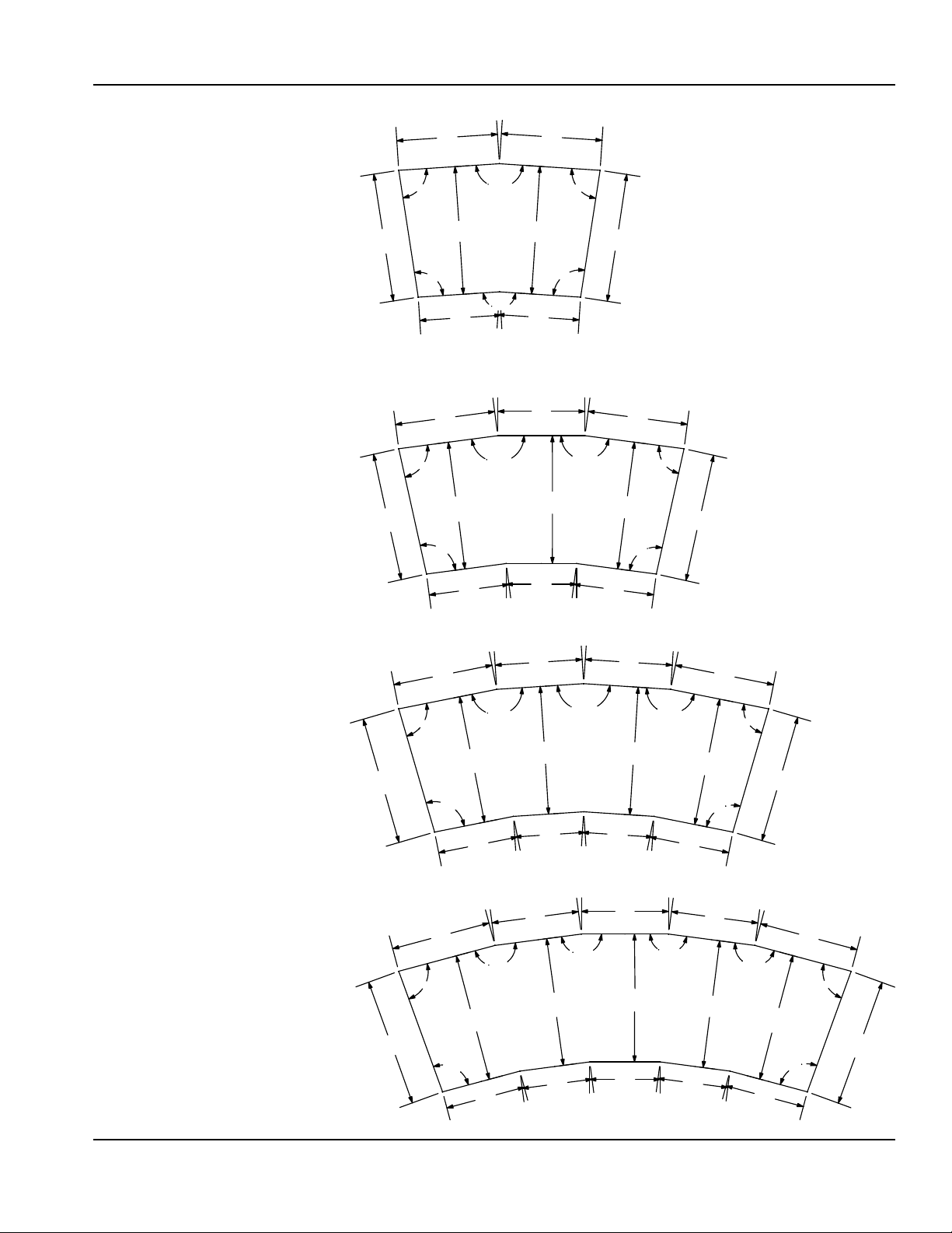
CURVED DROPIN CUTOUT DETAILS
2 pan standard curved drop-in cutout detail
for models:
• N8044-R
• N8144-BR
• N8744-R
3 pan standard curved drop-in cutout detail
for models:
• N8059-R
• N8159-BR
• N8759-R
25.10”
64cm
25.10”
64cm
85˚
85˚
95˚
19.75”
50cm
19.56”
50cm
95˚
25.00”
64cm
15.92”
40cm
25.00”
64cm
172.50˚
172.50˚
172.50˚
25.00”
64cm
15.92”
40cm
17.06”
43cm
19.75”
50cm
25.00”
64cm
95˚
85˚
172.50˚
25.10”
64cm
25.00”
64cm
19.56”
50cm
95˚
85˚
25.10”
64cm
4 pan standard curved drop-in cutout detail
for models:
• N8076-R
• N8176-BR
• N8776-R
5 pan standard curved drop-in cutout detail
or models:
• N8094-R
• N8194-BR
• N8794-R
25.10”
64cm
25.10”
64cm
85˚
172.50˚
172.50˚
13.78”
35cm
17.06”
43cm
25.00”
64cm
17.06”
43cm
13.78”
35cm
25.00”
64cm
13.78”
35cm
15.73”
40cm
19.56”
50cm
25.00”
64cm
95˚
15.73”
40cm
19.50”
50cm
85˚
25.00”
64cm
95˚
15.67”
40cm
172.50˚
172.50˚
15.73”
40cm
13.78”
35cm
17.06”
13.78”
17.06”
43cm
25.00”
64cm
43cm
25.00”
64cm
35cm
172.50˚
172.50˚
15.73”
40cm
13.78”
35cm
25.00”
64cm
17.06”
43cm
25.00”
64cm
19.56”
50cm
95˚
85˚
172.50˚
15.67”
40cm
25.10”
64cm
25.00”
64cm
95˚
19.50”
50cm
85˚
25.10”
64cm
Part Number: 8000_SM 07/18 15
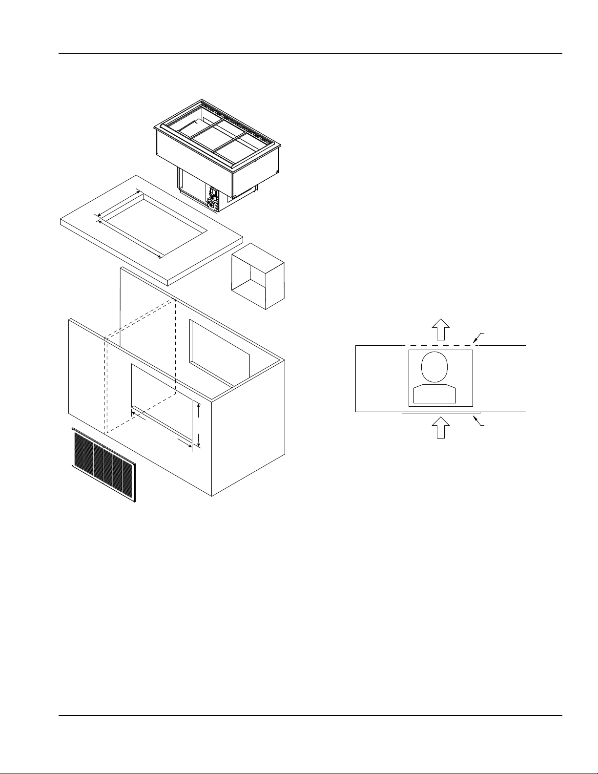
Page 16
Installation Section 2
Counter Cutout Dimensions
Are Model Specic
Drop-In Counter Installation
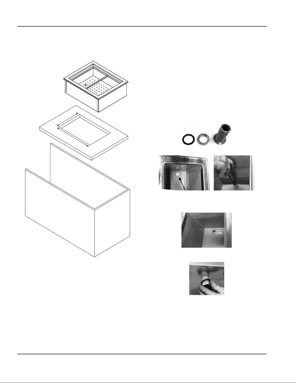
ICE COOLED DROPIN UNITS
N8000, N8000N, N8000-R
1. Place the ice cooled drop-in unit through the counter
cutout.
2. A gasket is installed in the flange of each unit.
The weight of the unit on the gasket forms a seal
preventing liquids from seeping into the cut-out
opening.
3. The 1” diameter drain on N8000, N8000N, N8000-R
models is shipped loose and must be connected during
installation.
A. Provided 1” (25mm) drain, nut and washer must
be field installed to an appropriate container or
floor drain following local code requirements.
Sinks come standard with 1-1/2” basket strainer
assemblies.
B. Remove/drill foam out of drain hole.
C. Apply thin ring of plumbers putty around the
drain.
D. From the inside drop the drain into the drain hole.
E. From the outside secure the drain with the washer
and nut.
F. Tighten the nut with channel locks, use a fork to
hold the drain in place if necessary.
G. Clean up excess plumbers putty.
16 Part Number: 8000_SM 07/18
Page 17
Section 2 Installation
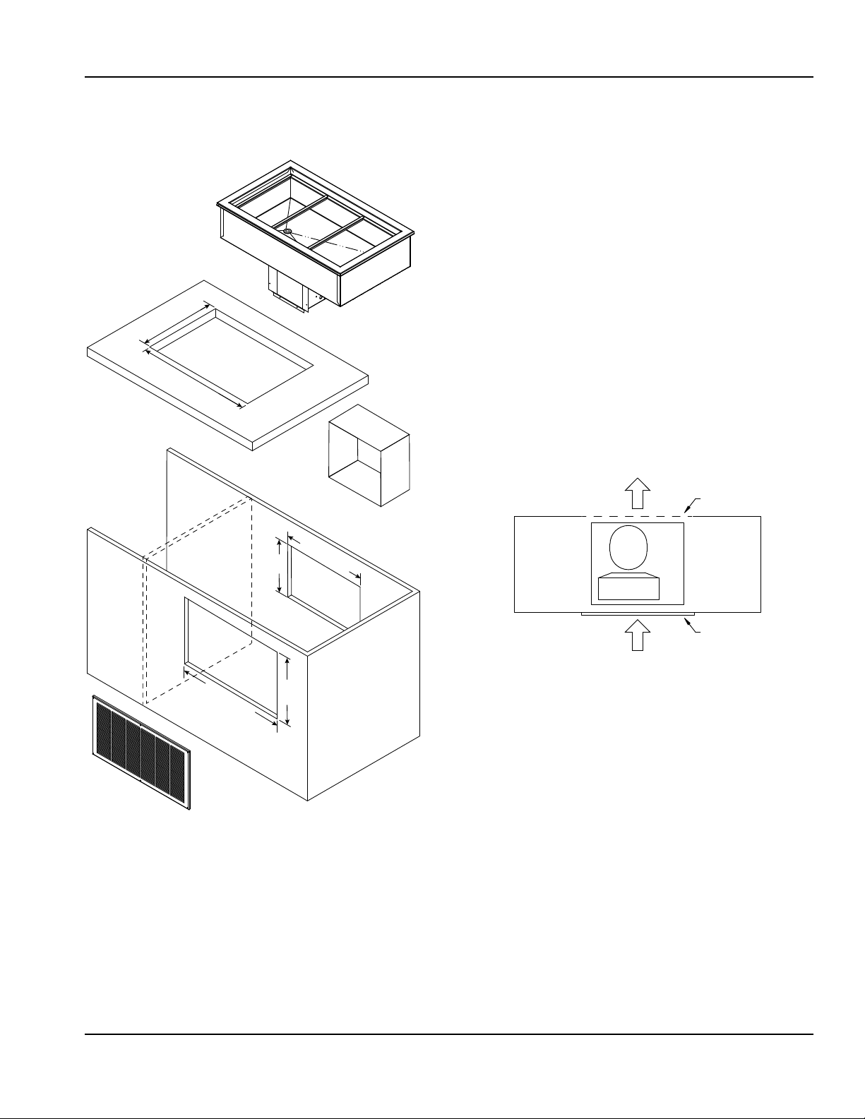
SELFCONTAINED REFRIGERATED DROPIN UNITS
8100-EF(N), N8100B, N8100-BR, N8100NB, N8200,
N8200G, N8200-ST
Counter Cutout Dimensions
Are Model Specic
Air duct dimensions
to match condenser face
11.00” (28cm)
8.00”
(20cm)
1. Install partitions between self-contained refrigerated
drop-in units and other electrical appliances if they
are located in the same cabinet. Partitions must fully
extend front to back and top to bottom.
2. Install a GFCI receptacle a minimum of 14” (36cm) up
from the cabinet bottom inside the partitions. Run the
outlet to a switch. With limited access to the control, a
switch will make it easy to turn the unit off for defrost.
3. The unit requires airflow to the compressor. One louver
is provided with each unit.
NOTE: Any restriction to the proper air flow will void the
compressor warranty.
• A 13” x 25” (33 cm x 64 cm) louver is provided by
Delfield and must be installed in the counter in front
of the condenser. The louver cutout dimension is 22”
x 11” (56 cm x 28 cm).
• The rear must have an opening for removal of
heated air. The opening must be at least 11” x 8”, a
total of 88 square inches (28cm x 20cm, a total of
566 square centimeters).
Discharge Air
Cutout
Condenser
22.0” (56cm)
11.00”
(28cm)
Louver
Fresh Air
4. Place the condensing unit through the counter cutout.
5. A gasket is installed in the flange of each unit.
The weight of the unit on the gasket forms a seal
preventing liquids from seeping into the cut-out
opening.
6. Plumb to a floor drain.
• 8100-EF(N) models have a 1/2” ID PVC drain.
• N8200 and N8200-ST models have a 1/2” OD
stainless steel drain. Use clear flexible tubing.
• N8200G models have a 3/4” drain located on end/
center. Use a 3/4” female coupling.
Part Number: 8000_SM 07/18 17
Page 18
Installation Section 2
to match condenser face
7. The 1” diameter drain on N8100B, N8100-BR and
N8100NB models is shipped loose and must be
connected during installation.
A. Provided 1” (25mm) drain, nut and washer must
be field installed to an appropriate container or
floor drain following local code requirements.
Sinks come standard with 1-1/2” basket strainer
assemblies.
B. Remove/drill foam out of drain hole.
C. Apply thin ring of plumbers putty around the
drain.
D. From the inside drop the drain into the drain hole.
8. Construct an air duct (not provided) connecting
the condenser face to the louver. This will prevent
recirculation of discharge air.
Air duct dimensions
E. From the outside secure the drain with the washer
and nut.
F. Tighten the nut with channel locks, use a fork to
hold the drain in place if necessary.
G. Clean up excess plumbers putty.
18 Part Number: 8000_SM 07/18
Page 19
Section 2 Installation
FORCEDAIR REFRIGERATED DROPIN UNITS
N8100-FA
Counter Cutout Dimensions
Are Model Specic
Air duct dimensions
to match condenser face
1. Install partitions between self-contained refrigerated
drop-in units and other electrical appliances if they
are located in the same cabinet. Partitions must fully
extend front to back and top to bottom.
2. Install a GFCI receptacle a minimum of 14” (36cm) up
from the cabinet bottom inside the partitions. Run the
outlet to a switch. With limited access to the control, a
switch will make it easy to turn the unit off for defrost.
3. The unit requires airflow to the compressor. One louver
is provided with each unit.
NOTE: Any restriction to the proper air flow will void the
compressor warranty.
• A 13” x 25” (33 cm x 64 cm) louver is provided by
Delfield and must be installed in the counter in front
of the condenser. The louver cutout dimension is 22”
x 11” (56 cm x 28 cm).
• The rear must have an opening for removal of
heated air. The opening must be at least 174in2
(1123cm2).
Discharge Air
Cutout
22.0” (56cm)
11.00”
(28cm)
Condenser
Louver
Fresh Air
4. Place the condensing unit through the counter cutout.
5. A gasket is installed in the flange of each unit.
The weight of the unit on the gasket forms a seal
preventing liquids from seeping into the cut-out
opening.
Part Number: 8000_SM 07/18 19
Page 20
Installation Section 2
6. The 1” diameter drain on N8100-FA models is shipped
loose and must be connected during installation.
N8157-FA, N8169-FA and N8182-FA have two 1” drains.
A. Provided 1” (25mm) drain, nut and washer must
be field installed to an appropriate container or
floor drain following local code requirements.
Sinks come standard with 1-1/2” basket strainer
assemblies.
B. Remove/drill foam out of drain hole.
C. Apply thin ring of plumbers putty around the
drain.
D. From the inside drop the drain into the drain hole.
7. Construct an air duct (not provided) connecting
the condenser face to the louver. This will prevent
recirculation of discharge air.
8. Inside the well, the fan assembly has standoff brackets
with tabs. The tabs should be bent up.
9. Place the coil assembly cover slots over the bracket
tabs. This will secure the cover is in the correct location
and will not disrupt the air flow.
10. The upright air diffuser will only fit one way on the
drain side.
Black Airow Extrusions
Perforated Pan Clip
Adapter Bars
E. From the outside secure the drain with the washer
and nut.
F. Tighten the nut with channel locks, use a fork to
hold the drain in place if necessary.
G. Clean up excess plumbers putty.
Coil Assembly Cover
Plexiglas
End Caps
Upright Air Diuser
With Air Deector
20 Part Number: 8000_SM 07/18
Page 21

Section 2 Installation
to match condenser face
SELFCONTAINED COMBO HOT/COLD DROPIN UNITS
N8600
Counter Cutout Dimensions
Are Model Specic
Air duct dimensions
to match condenser face
11.00” (28cm)
8.00”
(20cm)
Control Panel
Cutout Dimensions
Are Model Specic
22.0” (56cm)
11.00”
(28cm)
NOTE: Any restriction to the proper air flow will void the
compressor warranty.
• A 13” x 25” (33 cm x 64 cm) louver is provided by
Delfield and must be installed in the counter in front
of the condenser. The louver cutout dimension is 22”
x 11” (56 cm x 28 cm).
• The rear must have an opening for removal of
heated air. The opening must be at least 11” x 8”, a
total of 88 square inches (28cm x 20cm, a total of
566 square centimeters).
Discharge Air
Cutout
Condenser
Louver
Fresh Air
4. Orient the control panel with the indicator light for
each control to the right of the control. N8600 series
units have 40” (102cm) of conduit.
5. Place the control panel into the cutout from inside the
cabinet. Place the collar into the cutout from outside
the cabinet. Secure with two screws.
6. Place the condensing unit through the counter cutout.
7. A gasket is installed in the flange of each unit.
The weight of the unit on the gasket forms a seal
preventing liquids from seeping into the cut-out
opening.
8. N8600 wells are sloped to a 1” (25mm) male NPT
stainless steel drain. Plumb to a floor drain. Use a 1”
female coupling.
9. Construct an air duct (not provided) connecting
the condenser face to the louver. This will prevent
recirculation of discharge air.
1. Install partitions between self-contained refrigerated
drop-in units and other electrical appliances if they
are located in the same cabinet. Partitions must fully
extend front to back and top to bottom.
2. Install a GFCI receptacle a minimum of 14” (36cm) up
from the cabinet bottom inside the partitions.
3. The unit requires airflow to the compressor. One louver
is provided with each unit.
Part Number: 8000_SM 07/18 21
Air duct dimensions
Page 22

Installation Section 2
HOT FOOD WELL DROPIN UNITS
N8700-D, N8700-DESP, N8700N, N8700-R, N8800
Counter Cutout Dimensions
Are Model Specic
Control Panel
Cutout Dimensions
Are Model Specic
1. Orient the control panel with the indicator light for
each control to the right of the control.
• N8700 series units have 48” (122cm) of conduit.
• N8800 Series units have 34” (86cm) of conduit.
2. N8700 control panel is designed to be installed on the
side opposite the drains.
• Installed on the same side as the drains, the control
panel will either be upside down or the knobs will
control the opposite wells.
Control
panel
installed
opposite
drains
Drains
Infinite control shown, directions also apply to digital control
3. Place the control panel into the cutout from inside the
cabinet. Place the collar into the cutout from outside
the cabinet. Secure with two screws.
4. Place the hot food well drop-in unit through the
counter cutout.
5. A gasket is installed in the flange of each unit.
The weight of the unit on the gasket forms a seal
preventing liquids from seeping into the cut-out
opening.
6. Plumb to a floor drain.
• All N8700 series are equipped with 1/2” (13mm)
female NPT drains, one per well located right rear
corner, manifold to 1/2” (13mm) gate valve.
• N8800 wells are sloped to a 1” (25mm) male NPT
stainless steel drain. Use a 1” female coupling.
22 Part Number: 8000_SM 07/18
Page 23

Section 2 Installation
Electrical Service
DANGER
Check all wiring connections, including factory
terminals, before operation. Connections can become
loose during shipment and installation.
Warning
n
This appliance must be grounded and all field wiring
must conform to all applicable local and national
codes. Refer to rating plate for proper voltage. It is the
responsibility of the end user to provide the disconnect
means to satisfy the authority having jurisdiction.
VOLTAGE
All electrical work, including wire routing and grounding,
must conform to local, state and national electrical codes.
The following precautions must be observed:
• The equipment must be grounded.
• A separate fuse/circuit breaker must be provided for
each unit.
• A qualified electrician must determine proper wire size
dependent upon location, materials used and length
of run (minimum circuit ampacity can be used to help
select the wire size).
• The maximum allowable voltage variation is ±10% of
the rated voltage at equipment start-up (when the
electrical load is highest).
• Check all green ground screws, cables and wire
connections to verify they are tight before start-up.
GROUND FAULT CIRCUIT INTERRUPTER
Ground Fault Circuit Interrupter (GFCI/GFI) protection is
a system that shuts down the electric circuit (opens it)
when it senses an unexpected loss of power, presumably
to ground. Manitowoc does not recommend the use of
GFCI/GFI circuit protection to energize our equipment. If
code requires the use of a GFCI/GFI then you must follow
the local code. The circuit must be dedicated, sized
properly and there must be a panel GFCI/GFI breaker. We
do not recommend the use of GFCI/GFI outlets to energize
our equipment as they are known for more intermittent
nuisance trips than panel breakers.
ELECTRICAL SPECIFICATIONS CHART
Units with plugs are supplied with approximately 6ft
(183cm) cords.
Model Amps Watts V, Hz, Ph Plug
8100-EF Series
8118-EF
8132-EF
8145-EF
8159-EF
8172-EF
8186-EF 8.0
8118-EF-E
8132-EF-E
8145-EF-E
8159-EF-E
8172-EF-E
8186-EF-E
8148-EFN
8191-EFN
8148-EFN-E
8169-EFN-E
8191-EFN-E
N8118B
N8130B
N8143B
N8156B
N8169B
N8181B 7.3
N8118B-E
N8130B-E
N8143B-E
N8156B-E
N8169B-E
N8144-BR 4.0
N8159-BR 7.0
N8176-BR 7.3
N8194-BR 8.0
N8131-FA 7.8
N8144-FA
N8157-FA
N8169-FA
N8182-FA
N8146NB 3.7
N8168NB 5.6
7.5
8100-EF-E Export Series
2.5 600 230-240, 50, 1
7.5 - 115, 60, 1 NEMA 5-15P8169-EFN
8100-EFN-E Export Series
2.5 600 230-240, 50, 1
N8000N Series - NA
N8000-R Series - NA
3.7
5.6
N8100B-E Export Series - R404A
1.5 360 230-240, 50, 1
N8100B-E Export Series - R134A
2.5 600 230-240, 50, 1
9.2
14.8
- 115, 60, 1 NEMA 5-15P
8100-EFN Series
N8000 Series - NA
N8100B Series
- 115, 60, 1 NEMA 5-15P
N8100BR Series
- 115, 60, 1 NEMA 5-15P
N8100-FA Series
- 115, 60, 1 NEMA 5-15P
N8100NB Series
- 115, 60, 1 NEMA 5-15P
Varies Per
Destination
Varies Per
Destination
Varies Per
Destination
Varies Per
Destination
Part Number: 8000_SM 07/18 23
Page 24

Installation Section 2
Model Amps Watts V, Hz, Ph Plug
N8100NB-E Export Series
N8146NB-E
N8168NB-E
N8231
N8245
N8259
N8273
N8287 8.0
N8231-E
N8245-E 360
N8259-E
N8273-E 600
N8287-E 2.8 650
N8231G
N8245G
N8259G 8.0
N8273G 9.0
N8231G-E
N8245G-E
N8259G-E 2.8 672
N8230-ST
N8240-ST
N8256-ST
N8258-ST
N8275-ST
N8630 24.0 - 120, 60, 1
N8643
N8656
N8669
N8681
N8717-D 8.3
N8731-D 16.6
N8745-D 15.0/16.0
N8759-D 20.0/22.0
N8773-D 24.0/27.0
N8787-D 29.0/32.0
N8717-D-E 6.0 1450
N8731-D-E 12.1 2900
N8745-D-E 18.1 4350
N8759-D-E 24.2 5800
N8773-D-E 30.2 7250
N8787-D-E 36.3 8700
N8717-DESP 2.4/2.7
N8731-DESP 4.8/5.4
N8745-DESP 7.2/8.1
N8759-DESP 9.6/10.8
N8773-DESP 12.0/13.5
N8787-DESP 14.4/16.2
1.5 360 230-240, 50, 1
N8200 Series
7.5
N8200-E Export Series
1.5
2.5
7.5
N8200G-E Export Series
1.5 360
7.5 - 115, 60, 1 NEMA 5-15P
21.0
43.0
N8700D-E Export Series
- 115, 60, 1 NEMA 5-15P
360
230-240, 50, 1
600
N8200G Series
- 115, 60, 1 NEMA 5-15P
230-240, 50, 1
N8200-ST Series
N8600 Series
- 120/240, 60, 1
N8700D Series
- 120, 60, 1
- 208-230, 60, 1
240, 50, 1 Hard Wire
N8700DESP Series
- 208-230, 60, 1 Hard Wire
Destination
Destination
Destination
Varies Per
Varies Per
Varies Per
Hard Wire
Hard Wire
Model Amps Watts V, Hz, Ph Plug
N8700-D-ESP-E Export Series
N8717-D-ESP-E 2.1 500
N8731-D-ESP-E 4.2 1000
N8745-D-ESP-E 6.3 1500
N8759-D-ESP-E 8.4 2000
N8773-D-ESP-E 10.5 2500
N8787-D-ESP-E 12.6 3000
N8700N Series
N8746ND 17.0 - 120, 60, 1
N8768ND
N8744-R 16.6 - 120, 60, 1
N8759-R 15.0/16.0
N8794-R 24.0/27.0
N8831 17.0 - 120, 60, 1
N8845 15.0/16.0
N8859 20.0/22.0
N8873 24.0/27.0
N8887 29.0/32.0
N8831-E 12.1 2900
N8845-E 18.1 4350
N8859-E 24.2 5800
N8873-E 30.2 7250
N8887-E 36.3 8700
15.0/16.0 - 208-230, 60, 1
N8700-R Series
- 208-230, 60, 1N8776-R 20.0/22.0
N8800 Series
- 208-230, 60, 1
N8800-E Export Series
240, 50, 1 Hard Wire
240, 50, 1 Hard Wire
Hard WireN8768N
Hard Wire
Hard Wire
24 Part Number: 8000_SM 07/18
Page 25

Section 2 Installation
BTU
Refrigeration
Temperature Class for all Export units is N.
BTU
Model H.P.
8100-EF Series R404A
8118-EF 1/4 204 19/50º/-15° 928
8132-EF 1/4 379 26/42º/-7° 1112
8145-EF 1/4 569 35/36º/-1° 1259
8159-EF 1/4 758 43/32º/3° 1373
8172-EF 1/4 948 51/29º/6° 1469
8186-EF 1/3 1138 59/26º/9° 1529 24.0oz
8100-EF-E Export Series R404A
8118-EF-E 1/4 204 19/50º/-15° 928
8132-EF-E 1/4 379 26/42º/-7° 1112
8145-EF-E 1/4 569 35/36º/-1° 1259
8159-EF-E 1/4 758 43/32º/3° 1373
8172-EF-E 1/4 948 51/29º/6° 1469
8186-EF-E 1/3 1138 59/26º/9° 1529
8100-EFN Series R404A
8148-EFN 1/4 379 26/42º/-7° 1112
8191-EFN 1/4 758 43/32º/13° 1373
8100-EFN-E Export Series R404A
8148-EFN-E 1/4 379 26/42º/-7° 1112
8191-EFN-E 1/4 758 43/32º/13° 1373
N8000N Series - NA
N8000-R Series - NA
N8100B Series R404A
N8118B 1/5 204 19/38º/-3º 1010 6.0oz
N8130B 1/5 379 26/31º/4° 1298 7.5oz
N8143B 1/5 569 35/26º/9º 1298 9.2oz
N8156B 1/4 758 43/32º/3º 1961 6.5oz
N8169B 1/4 948 51/29º/6º 2088 6.5oz
N8181B 1/3 1138 59/32º/3º 2088 7.5oz
N8100B-E Export Series R404A
N8118B-E 1/5 204 19/38º/-3º 708
N8143B-E 1/5 569 35/26º/9º 889
N8100B-E Export Series R134A
N8156B-E 1/4 758 43/32º/3º 1373
N8169B-E 1/4 948 51/29º/6º 1469
N8100BR Series R404A
N8144-BR 1/5 379 26/31º/4° 812 9.4oz
N8159-BR 1/4 569 35/26º/9º 889 6.5oz
N8176-BR 1/3 758 43/32º/3º 1373 7.5oz
N8194-BR 1/3 948 51/29º/6º 1469 7.9oz
N8100-FA Series R404A
N8131-FA 1/4 1339 140/15º/20º 2154 16.0oz
N8144-FA 1/2 2035 140/22º/13º 3142 32.0oz
N8157-FA 1/2 2731 280/14º/21° 3806 32.0oz
N8169-FA 3/4 3374 280/20º/15° 5545 48.0oz
N8182-FA 3/4 4070 280/20º/15° 5545 48.0oz
N8100NB Series R134A
N8146NB 1/5 454 17/40º/-5º 680 8.5oz
N8168NB 1/5 676 26/31º/4º 804 6.5oz
N8100NB-E Export Series R404A
N8146NB-E 1/5 454 17/40º/-5º 680
N8168NB-E 1/5 676 26/31º/4º 804
Evap BTU/TD/
Load
N8000 Series NA
TEMP
Sys Cap
Refrig.
Charge
16.0oz
454g
16.0oz8169-EFN 1/4 569 35/36º/-1° 1259
454g8169-EFN-E 1/4 569 35/36º/-1° 1259
454gN8130B-E 1/5 379 26/31º/4° 812
227g
454g
Model H.P.
N8200 Series R404A
N8231 1/4 379 26/42º/-7° 1112
N8245 1/4 569 35/36º/-1° 1259
N8259 1/4 758 43/32º/3° 1373
N8273 1/4 948 51/29º/6° 1469
N8287 1/3 1138 59/30º/5° 1787 24.0oz
N8200-E Export Series R404A
N8231-E 1/5 379 26/42º/-7° 1112
N8245-E 1/5 569 35/36º/-1° 1259
N8259-E 1/4 758 43/32º/3° 1373
N8273-E 1/4 948 51/29º/6° 1469
N8287-E 1/3 1138 59/30º/5° 1787
N8200G Series R404A
N8231G 1/4 379 26/42º/-7° 1112 16.0oz
N8245G 1/4 569 35/36º/-1° 1259 16.0oz
N8259G 1/3 758 43/37º/-2° 1572 24.0oz
N8273G 1/2 948 51/43º/-8° 2183 40.0oz
N8200G-E Export Series R404A
N8231G-E 1/5 379 26/42º/-7° 1112
N8259G-E 1/3 758 43/37º/-2° 1572
N8200-ST Series R404A
N8230-ST 1/4 332 26/44°/-9° 1128
N8240-ST 1/4 559 35/37°/-2° 1295
N8256-ST 1/4 624 39/35°/0° 1359
N8258-ST 1/4 870 44/33°/2° 1422
N8275-ST 1/4 1140 53/29°/6° 1520
N8600 Series R404A
N8630 1/4 379 26/42º/-7° 1112
N8643 1/4 569 35/36º/-1° 1259
N8656 1/4 758 43/32º/3° 1373
N8669 1/4 948 51/29º/6° 1469
N8681 1/3 1138 59/30º/5° 1787 24.0oz
N8700D Series - NA
N8700D-E Export Series - NA
N8700DESP Series - NA
N8700-D-ESP-E Export Series - NA
N8700N Series - NA
N8700-R Series - NA
N8800 Series - NA
N8800-E Export Series
Load
Evap BTU/TD/
TEMP
Sys Cap
Refrig.
Charge
16.0oz
454g
454gN8245G-E 1/5 569 35/36º/-1° 1259
16.0oz
16.0oz
Part Number: 8000_SM 07/18 25
Page 26

Installation Section 2
Optional Auto Fill Installation
• Option is a loose parts kit. Installation requires a plumber.
• The purpose of the auto fill assembly is to maintain the level of water lost throughout operation as it steams away. If
using it to fill an empty unit it will fill slowly and you may want to start by manually filling the unit.
APPLICABLE TO N8600 & N8800 MODELS
1. Locate mounting holes on outside operator drop-in body and mount float and bracket using thumb screws.
2. Install drain plumbing as shown.
3. Connect clear plastic tubing to 1/2” copper stub and connect to the float. Use hose clamps to secure.
4. Connect fill line to 1/4” compression fitting.
5. Loosen thumb screws to achieve desired water level.
NO CONNECTION
NEEDED
26 Part Number: 8000_SM 07/18
Page 27

Section 2 Installation
Optional Auto Fill Installation
• Option is a loose parts kit. Installation requires a plumber.
• The purpose of the auto fill assembly is to maintain the level of water lost throughout operation as it steams away. If
using it to fill an empty unit it will fill slowly and you may want to start by manually filling the unit.
APPLICABLE TO N8700 MODELS
1. Locate mounting holes on outside operator drop-in body and mount float and bracket using thumb screws.
2. Install drain plumbing as shown.
3. Connect clear plastic tubing to 1/2” copper stub and connect to the float. Use hose clamps to secure.
4. Connect fill line to 1/4” compression fitting.
5. Loosen thumb screws to achieve desired water level.
NO CONNECTION
NEEDED
Part Number: 8000_SM 07/18 27
Page 28

Installation Section 2
THIS PAGE INTENTIONALLY LEFT BLANK
28 Part Number: 8000_SM 07/18
Page 29

Section 3
Operation
DANGER
The on-site supervisor is responsible for ensuring that
operators are made aware of the inherent dangers of
operating this equipment.
DANGER
Do not operate any appliance with a damaged cord
or plug. All repairs must be performed by a qualified
service company.
DANGER
Never stand on the unit! They are not designed to
hold the weight of an adult, and may collapse or tip if
misused in this manner.
Warning
n
Do not contact moving parts.
Warning
n
All covers and access panels must be in place and
properly secured, before operating this equipment.
Product Quality in Cold Pans
Warning
n
The operator of this equipment is solely responsible
for ensuring safe holding temperature levels for all
food items. Failure to do so could result in unsafe food
products for customers.
These units are not designed to cool warm food products.
Items should be placed in the unit pre-cooled at least to the
desired holding temperature, if not slightly colder. In some
applications, a gradual warming of product may occur,
particularly at the exposed top of the product. Stirring or
rotation of the product is necessary to maintain overall
temperature.
Warming of food product can occur very quickly outside of
the unit. When loading or rotating product, avoid leaving
food items in a non-refrigerated location for any length of
time to prevent warming or spoilage. To ensure product
quality product must be rotated every four hours.
Warning
n
Damp or wet hands may stick to cold surfaces.
Warning
n
Never use sharp objects or tools to remove ice or frost.
Do not use mechanical devices or other means to
accelerate the defrosting process.
Warning
n
Do not block the supply and return air grills or the air
space around the air grills. Keep plastic wrappings,
paper, labels, etc. from being airborne and lodging in
the grills. Failure to keep the air grills clear will result in
unsatisfactory operation of the system.
Caution
,
Units with pans should be operated with pans in place.
Operating the unit without all pans in place will lower
efficiency and may damage the unit.
Part Number: 8000_SM 07/18 29
Page 30

Operation Section 3
8100-EF(N) Series Operation
Note
The cold pan is not intended to be used with ice.
There is a switch on the compressor housing front to turn
the 8100-EF units on and off. The unit must be turned off
when not in use or overnight for defrosting and cleaning.
8100-EF Series LiquiTec® Eutetic fluid cold pans are adjusted
at the factory to provide proper operation without any
further adjustments.
The temperature control is located on the condensing
housing.
Power Switch & Temperature Control
1. At initial start-up or anytime power is disconnected,
then reconnected to the unit, the control will go into
normal cooling mode.
2. The temperature control will cycle the compressor and
condenser fan motor to maintain proper temperature.
Notice
Temperature displayed is for refrigeration set point
purposes only. Display does not reflect air or product
temps in unit.
TEMPERATURE CONTROL & DISPLAY
V
V
Operation / Indication
Status Displayed
Normal (°C) Temp. [°C] Unit depends on setting
Normal (°F) Temp. [°F]
Show set-point Temp.
Sensor 1 defect
Sensor 2 defect
Sensor 3 defect
Sensor 4 defect
High temperature
alarm
Low temperature alarm
Line voltage too high,
above 140 volts
Line voltage too low,
below 96 volts
Control calls for cooling
for more than 24 hours
straight
All alarms sound for approximately 10 seconds and then
E01
E02
E03
E04
Hi
Lo
uHi
uLi
LEA
X Air sensor
X Coil sensor
X Open
X Open
X Automatically switching
X
X
X
X Time includes defrost.
are silent for 50 seconds. It will do that for 15 cycles and
then remain silent. The alarm code will still be present on
the display until the fault clears.
Comments
(parameters in control)
at 2 sec rate
Error will go away if the
control cycles off the
compressor or if the
power is shut off. If error
is on a cold pan it could
be related to a high
ambient temperature or
not shutting the rail off
nightly.
30 Part Number: 8000_SM 07/18
Page 31

Section 3 Operation
Press upper or lower right button.
• Display show actual set-point (blinking).
• If buttons untouched for 3 seconds returns to
normal.
• Increase set-point by pressing upper button. Max value
depends on parameters in control.
• Decrease set-point by pressing lower button. Min value
depends on parameters in control.
• If buttons untouched for 3 seconds returns to
normal and stores new set-point.
Press lower left button for 5 seconds.
• Unit goes into stand-by mode.
• The display will read Off, then a period.
• Press the lower left button again for 5 seconds.
• The display will read On.
• The unit will then start up in normal cooling
mode.
Temperature Alarm
The alarm will sound and flash HI or LO 90 minutes after the
unit has reached its alarm temperature point or after any
power interruption if the temperature is above or below the
alarm set points.
CHANGING DISPLAY FROM FAHRENHEIT TO CELSIUS
ON ERC112 CONTROL
1. Simultaneously hold the up and down arrows for
5 seconds to access menu for password protected
parameters.
2. Screen should temporarily flash PAS and then move to
a numeric screen.
3. Scroll to 187 using the up/down arrows and push the
stand-by button (lower left button) to enter.
4. Scroll to dis using the up/down arrows and push the
stand-by button (lower left button) to enter into the
display menu.
5. Scroll to CFu using the up/down arrows and push the
stand-by button (lower left button) to enter the display
unit menu.
Part Number: 8000_SM 07/18 31
Page 32

Operation Section 3
6. -F should be displayed indicating Fahrenheit. Use
the down arrow to change it to -C for Celsius and hit
the stand-by button (lower left button) to enter the
change.
7. Push the defrost button (upper left button) to move
out of the display unit menu.
N8100B, N8100-BR & N8100NB Operation
The temperature control is used to turn the unit on and
off as well as control the temperature of the cold pan. The
control is located in the machine compartment. To turn the
cold pan off, turn the knob to the off position. The unit must
be turned off when not in use or overnight for defrosting
and cleaning.
If the cold pan is to be used with ice, it is recommended
that the optional perforated bottoms be used. These will
allow ice to melt properly.
These mechanically cooled cold pans are adjusted at
the factory to provide proper operation. However, if it
is necessary to adjust the temperature, turn the knob
clockwise as indicated on the control. Settings are from 1
thru 7 (7 being the coldest).
• Adjustments should be made gradually.
• Several small adjustments will be more effective than
one large adjustment.
• It may take an hour or longer to realize the temperature
change depending on the application and location of
the unit.
8. Push the defrost button (upper left button) to move
out of the display menu and back to the normal display.
NOTE: For steps 7 and 8, display will return back to normal
display after 30 seconds of inactivity.
32 Part Number: 8000_SM 07/18
Page 33

Section 3 Operation
N8100-FA Operation
There is a switch on the compressor housing front to turn
the N8100-FA units on and off. The unit must be turned off
when not in use or overnight for defrosting and cleaning.
NOTE: Food in the N8100-FA pans should not be loaded in
such a way as to interfere with the air curtain flowing over
the cold pans.
Defrost Timer
The recommended defrost timer setting is every 2 hours for
15 minutes.
Pressure Control
The temperature is controlled by an adjustable pressure
control located in the machine compartment and
adjustable control has the word COLDER near the knob,
with an arrow to indicate the adjustment direction. This
control is field adjustable and does not require a service
agent. If you have any questions, call an authorized service
agent.
In attempting to adjust the pressure control, you can
do damage to the unit by accidentally adjusting the
differential.
NOTE: Delfield is not responsible for charges incurred while
adjusting the pressure control.
Factory settings are:
• 30 psi (207 kPa) differential
• 80 psi (552 kPa) cut-in
• 50 psi (345 kPa) cut-out
N8200 & N8200-ST Operation
N8200 and N8200-ST series frost tops are designed to
maintain an even layer of frost to pleasantly display
product. Once turned on, the compressor will run
continuously. There is no temperature control. The ON/OFF
switch is the only means available to cycle the unit.
Since it takes time for the frost to accumulate initially, the
unit should be turned on approximately one hour before it
is required. Product should not be placed on the frost top
prior to turning the unit on, because it may freeze to the
surface of the unit.
The unit must be turned off when not in use or overnight
for defrosting and cleaning.
Operation N8200G
N8200G Series granite cold slabs are designed to maintain
a low temperature surface for quick turn products such
as ice cream. Frost patterns will vary depending on room
conditions such as temperature, humidity and airflow. The
work zone of the granite surface is considered to be inside a
2.0” (5.1cm) perimeter. Temperatures in the perimeter zone
may be higher and again the frost patterns in this area will
vary based on room conditions.
Unit is controlled by an on/off switch. Once turned on, the
unit will run continuously. There is no temperature control
in this unit. Turn the unit on approximately two hours prior
to use to allow for ample cool down time. At 75˚F ambient
temperature the unit will reach operating temperature of
0˚F to 20˚F in 2 hours.
The unit must be turned off when not in use or overnight
for defrosting and cleaning.
Cut In Knob
Controlled
Dierential
Part Number: 8000_SM 07/18 33
Page 34

Operation Section 3
8600 Hot/Cold Series Operation
Hot Operation
DANGER
When operated at the highest temperature setting, the
top of the unit will become very hot. Staff and customers
using the equipment should be informed about this.
Caution
,
Never use anything other than plain water in the wells
or tank. Failure to observe this warning may result in
personal injury or damage to the unit.
Caution
,
Using ice in a hot food well can cause condensation and
damage to the well over time.
N8600 Series hot and cold combination pans must be
operated with water in the well for proper hot operation.
Fill well with a minimum of 4.0” (10.2cm) of water. Place
function switch in HOT position to begin heating. Turn
thermostat dial to the desired temperature.
To turn unit off, simply move the function switch to OFF
position. Drain water and allow unit to cool before cleaning
or switching to cold operation.
Switching From Hot To Cold Operation
1. Place the function switch in the OFF position and drain
out hot water.
2. Allow the unit to cool until it can be safely cleaned.
3. When clean up procedures are complete, unit will be
ready for cold operation. This takes about one hour.
Switching From Cold To Hot Operation
No special procedure is required to switch from the cold to
hot operation. Be certain to fill with a minimum of 4.0” of
water.
Note
The unit is designed so that the compressor and the
heating elements cannot operate at the same time.
Continued operation of the compressor in the hot
position is not normal. Call for service if this happens.
The unit must be turned off when not in use or overnight
for defrosting and cleaning.
N8600 Immersion Heater High Limit
As a safety feature, the N8600 food well immersion heater
includes a high limit safety switch. If the heater gets too
hot the safety switch will trip and turn the heater off. A
pilot light on the control panel will illuminate when the
safety switch is tripped. To reset the safety switch, first turn
OFF the thermostat or Power switch and then determine
if low water is the cause. If low water is not the cause,
contact service for resolution. If low water is the cause,
carefully remove food pans and refill the water. This will
allow the immersion heater to cool and the safety switch
will automatically reset. The unit must be turned OFF
as directed or safety switch will not reset even if water
is refilled to proper level. Replace food pans and turn
thermostat or Power switch back on.
Caution
,
To assure maximum compressor life, do not switch
from “hot” to “cold” operation without allowing a cool
down period. Never switch from hot to cold operation
while hot water remains in the pans. Failure to observe
this warning will greatly reduce compressor life and
eventually cause premature compressor failure.
Cold Operation
Simply place the function switch to the COLD position.
The compressor controller has been factory set and no
temperature adjustment should be necessary.
If the cold pan is to be used with ice, it is recommended
that the optional perforated bottoms be used. These will
allow ice to melt properly.
34 Part Number: 8000_SM 07/18
Page 35

Section 3 Operation
N8700-D, N8700N, N8700-R & N8800 Series
Operation
These units are designed to hold warm food product
between 140ºF to 160ºF (60ºC to 71ºC).
N8700-D, N8700N and N8700-R series individually heated
hot food units may be operated wet (with water in the
wells) or dry. Wet operation is recommended for better
performance.
N8800 Series single tank hot food units are designed to be
operated wet (with water in the tank) only.
Note
Proper water level is approximately 2.0” (5.1cm). It must
be maintained to prevent damage to the tank on the
N8800 Series units.
After the unit is hard wired to the electrical system, select
desired temperature by rotating temperature control. A
knob and indicator light are provided for each individual
heated food well.
First Time Use
Before the unit is used the first time for serving, turn the
temperature knob to HI and heat the well for 20 to 30
minutes.
Any residue or dust that adhered to the heater element(s)
will be burned off during this initial preheat period.
When serving thick sauces always use the hot food well in
wet operation. This provides more uniform temperature for
the sauce.
Note
Never place food directly in well. Always use pans.
For most efficient operation, keep covered inserts in each
well during preheating or when empty.
Always place covers on pans when not serving to prevent
food from drying out.
Wet Operation
DANGER
When operated at the highest temperature setting, the
top of the unit will become very hot. Staff and customers
using the equipment should be informed about this.
DANGER
Steam can cause serious burns. Always use some type
of protective covering on your hands and arms when
removing lids from the unit. Lift the lid in a way that will
direct escaping steam away from your face and body.
Caution
,
Never use anything other than plain water in the wells
or tank. Failure to observe this warning may result in
personal injury or damage to the unit.
Caution
,
Using ice in a hot food well can cause condensation and
damage to the well over time.
Fill the food well with a minimum of 2.0” (5.1cm) of water
and cover with lid or empty pan. To preheat water, set
temperature control at HI. With pans in place, wells will boil
water. Food temperature will vary depending on type and
amount of product. To minimize steam and water usage,
set control at lowest setting that will maintain proper food
temperature. To reduce preheating time, use hot water to
fill the well.
Dry Operation N8700 Series only
DANGER
When operated dry, the well bottoms become very
hot. Do not allow unprotected skin to contact any well
surface.
Wet operation is usually much more efficient and is
preferred. However, these units may be operated without
water with no damage to the unit.
When operated dry, the bottom of the well will discolor. To
clean, use a stainless steel cleaner or mild abrasive.
Part Number: 8000_SM 07/18 35
Page 36

Operation Section 3
N8700-DESP Operation
These units are designed to hold warm food product
between 140ºF to 160ºF (60ºC to 71ºC).
N8700-DESP series individually heated hot food units may
be operated wet (with water in the wells) or dry. However,
dry operation using 6.0” deep pans produces optimum
performance.
A power switch and digital control are provided for each
individual heated food well. After the unit is hard wired to
the electrical system, turn the power switch ON to energize
the control; the digital display will read OFF. Press Set and
then use the arrows to select the desired temperature
setting (1-10). The new temperature setting is entered 3
seconds after the last button is pressed. When the power
switch is used to turn the well OFF and back ON the
temperature setting will remain.
Note
Never place food directly in well. Always use pans.
For most efficient operation, keep covered inserts in each
well during preheating or when empty.
Always place covers on pans when not serving to prevent
food from drying out.
Dry Operation
Caution
,
Never use anything other than plain water in the wells
or tank. Failure to observe this warning may result in
personal injury or damage to the unit.
Caution
,
Using ice in a hot food well can cause condensation and
damage to the well over time.
Fill the food well with a minimum of 2” (5cm) of water
and cover with lid or empty pan. To preheat water, set
temperature control at 3. With pans in place, wells will boil
water. Food temperature will vary depending on type and
amount of product. To minimize steam and water usage,
set control at lowest setting that will maintain proper food
temperature. To reduce preheating time, use hot water to
fill the well. Preheating time with room temperature water
is one hour.
N8700-DESP Temperature Control Operation
LOAD
DANGER
When operated dry, the well bottoms become very
hot. Do not allow unprotected skin to contact any well
surface.
Dry operation is more efficient and is preferred.
When operated dry, the bottom of the well will discolor. To
clean, use a stainless steel cleaner or mild abrasive.
Wet Operation
DANGER
When operated at the highest temperature setting, the
top of the unit will become very hot. Staff and customers
using the equipment should be informed about this.
DANGER
Steam can cause serious burns. Always use some type
of protective covering on your hands and arms when
removing lids from the unit. Lift the lid in a way that will
direct escaping steam away from your face and body.
SET
• LED DISPLAY: Indicates the temperature setting 0-10. At
the first startup the display will read OFF.
• SET: When SET is depressed, the temperature setting is
displayed and can be adjusted with the arrows.
• LOAD LIGHT: Lit when well is heating.
• ARROWS: After pressing SET, press the Up-Arrow to
increase the temperature setting, press the DownArrow to decrease the temperature setting. The new
temperature setting is entered 3 seconds after the last
arrow is pressed.
Food Well Bottom Surface Temperatures
NOTE: Temperatures correspond to the food well bottom
surface; they do not represent product temperatures.
Control °F °C Control °F °C
1 161 72 6 266 130
2 182 83 7 287 142
3 203 95 8 308 153
4 224 107 9 329 165
5 245 118 10 350 177
36 Part Number: 8000_SM 07/18
Page 37

Section 3 Operation
Part Number: 8000_SM 07/18 37
Page 38

Section 4
Maintenance
DANGER
It is the responsibility of the equipment owner to
perform a personal protective equipment hazard
assessment to ensure adequate protection during
maintenance procedures.
DANGER
Failure to disconnect the power at the main power
supply disconnect could result in serious injury or death.
The power switch DOES NOT disconnect all incoming
power.
DANGER
Disconnect electric power at the main power disconnect
for all equipment being serviced. Observe correct
polarity of incoming line voltage. Incorrect polarity can
lead to erratic operation.
Warning
n
Never use sharp objects or tools to remove ice or frost.
Do not use mechanical devices or other means to
accelerate the defrosting process.
Cleaning and Sanitizing Procedures
Caution
,
Maintenance and servicing work other than cleaning as
described in this manual must be done by an authorized
service personnel.
GENERAL
Warning
n
When using cleaning fluids or chemicals, rubber gloves
and eye protection (and/or face shield) must be worn.
You are responsible for maintaining the equipment
in accordance with the instructions in this manual.
Maintenance procedures are not covered by the warranty.
Maintenance Daily Weekly Monthly
Exterior X X X
Gasket X X X
N8100-FA Series
Drain
Condenser Coil X X X
38 Part Number: 8000_SM 07/18
X X X
After Prolonged
Shutdown
At Start-Up
Page 39

Section 4 Maintenance
EXTERIOR CLEANING
Warning
n
When cleaning the unit, care should be taken to avoid
the front power switch and the rear power cord. Keep
water and/or cleaning solutions away from these parts.
Warning
n
Never use a high-pressure water jet for cleaning or
hose down or flood the units with water. Do not use
power cleaning equipment, steel wool, scrapers or wire
brushes on stainless steel or painted surfaces.
Caution
,
Never use an acid based cleaning solution, including a
delimer! Acid will deteriorate the finish and damage the
heating element. Food products can also be acidic, keep
equipment clean of ALL food products.
Clean the area around the unit as often as necessary to
maintain cleanliness and efficient operation.
Gaskets require daily cleaning to prevent mold and
mildew build up and also to retain the elasticity of the
gasket. Gasket cleaning can be done with the use of warm
soapy water (no citrus based cleaners). Avoid full strength
cleaning products on gaskets as this can cause them to
become brittle and crack. Never use sharp tools or knives to
scrape or clean the gasket.
Wipe surfaces with a damp cloth rinsed in water to remove
dust and dirt from the unit. Always rub with the “grain” of
the stainless steel to avoid marring the finish. If a greasy
residue persists, use a damp cloth rinsed in a mild dish soap
and water solution. Wipe dry with a clean, soft cloth.
Never use steel wool or abrasive pads for cleaning. Never
use chlorinated, citrus based or abrasive cleaners.
Stainless steel has a clear coating that is stain resistant and
easy to clean. Products containing abrasives will damage
the coating and scratch the panels. Daily cleaning may be
followed by an application of stainless steel cleaner which
will eliminate water spotting and fingerprints. Early signs of
stainless steel breakdown are small pits and cracks. If this
has begun, clean thoroughly and start to apply stainless
steel cleaners in attempt to restore the steel.
N8600 Immersion Heater
Follow the same as instructions as the rest of the food well:
Wipe surfaces with a damp cloth rinsed in water to remove
dust and dirt from the unit. If a greasy residue persists, use
a damp cloth rinsed in a mild dish soap and water solution.
Wipe dry with a clean, soft cloth. Never use steel wool or
abrasive pads for cleaning. Never use chlorinated, citrus
based or abrasive cleaners.
Defrosting
Refrigerated cold pans should be defrosted daily. Never
use sharp objects or tools to clean or scrape ice/frost build
up from the refrigerated cold pans. A puncture to the pan
could cause irreparable damage to the refrigeration system.
Units with a Eutectic Fluid Cold Pan require the same
precautions. The fluid is NOT refillable and loss of fluid due
to a puncture would cause irreparable damage.
CLEANING THE CONDENSER COIL
In order to maintain proper refrigeration performance, the
condenser fins must be cleaned of dust, dirt and grease
regularly. It is recommended that this be done monthly. If
conditions are such that the condenser is totally blocked
in a month, the frequency of cleaning should be increased.
Clean the condenser with a vacuum cleaner or stiff brush. If
extremely dirty, a commercially available condenser cleaner
may be required.
Failure to maintain a clean condenser coil can initially cause
high temperatures and excessive run times. Continuous
operation with a dirty or clogged condenser coil can
result in compressor failure. Neglecting the condenser coil
cleaning procedures will void any warranties associated
with the compressor and cost to replace the compressor.
N8100FA SERIES DRAIN MAINTENANCE
Each N8100-FA unit has a drain located inside the unit that
removes the condensation from the evaporator coil and
routes it to an external condensate evaporator pan. Each
drain can become loose or disconnected during normal use.
If you notice water accumulation under the unit, be sure the
drain tube is connected to the evaporator drain pan and the
end of the drain tube is in the condensate evaporator. The
leveling of the unit is important as the units are designed to
drain properly when level. Be sure all drain lines are free of
obstructions.
Part Number: 8000_SM 07/18 39
Page 40

Section 5
Troubleshooting
Problem -> Cause -> Correction Chart
Problem Cause Correction
Not running Fuse blown or circuit breaker tripped. Replace fuse or reset circuit breaker.
Power cord unplugged. Plug in power cord.
Power cord can also be unplugged from the unit.
Check both ends
Thermostat set too high. Set thermostat to lower temperature.
Main power switch turned off. Turn main power switch on.
Control is turned off
- indicated by singe blue dot.
Condensing
unit runs
without cooling
continuously
Temperature is too
high
Food temping too
high
Cabinet is noisy Loose part(s). Locate and tighten loose part(s).
Poor airflow to condenser coil or recirculation of
Make sure food is cold before loading into well.
Make sure no air is blowing onto well
Dirty condenser coil. Clean the condenser coil.
condenser air back through the coil.
Thermostat set too high. Set thermostat to lower temperature.
Warm product placed in well. Remove warm product and change with cold product,
Dirty condenser coil. Clean the condenser coil.
Iced over. Turn unit off and allow to defrost.
from vents or other equipment.
Turn control on by holding down the power button
(lower left button)
Provide fresh air to condenser.
See installation instructions.
preferably 34°-36°.
Stir food occasionally to help maintain product temp or
change product when out of temp.
Refrigerator is
freezing product
Compressor will
not start
Compressor will
not start and trips
overload
Thermostat is set too low. Set thermostat to higher temperature.
Product left in the well too long. Remove product at night or change when out of temp.
Stir food occasionally to help maintain product temp or
change product when out of temp.
Low voltage to cabinet. Check and correct incoming voltage to cabinet.
Low pressure switch open (R290 units). Check refrigerant level.
Open compressor windings, locked rotor
condition, or defective start components.
Check windings for open condition, check amp draw for
locked rotor condition, if none of the above exist change start
components.
Page 41

Section 6
Refrigeration
R404A
Refrigerant Recovery / Evacuation &
Recharging
Do not purge refrigerant to the atmosphere. Capture
refrigerant using recovery equipment by specific
manufacturer’s recommendations.
Important
We assume no responsibility for the use of contaminated
refrigerant. Damage resulting from the use of
contaminated refrigerant is the sole responsibility of the
servicing company.
Connections
1. Suction side of the compressor through the suction
service valve.
2. Discharge side of the compressor through the
discharge service valve.
Self-Contained Recovery/Evacuation
1. Disconnect power to the unit.
2. Install manifold gauges, charging cylinder/scale, and
recovery unit or two-stage vacuum pump.
3. Perform recovery or evacuation:
H. Recovery: Operate the recovery unit as directed by
the manufacturer’s instructions.
I. Evacuation prior to recharging:
Pull the system down to 250 microns. Then, allow
the pump to run for an additional half hour. Turn
off the pump and perform a standing vacuum leak
check.
NOTE: Check for leaks using halide or electronic leak
detector after charging the Reach-In.
Charging Procedures
Important
The charge is critical on all Reach-In units. Use a scale or a
charging cylinder to ensure the proper charge is installed.
1. Disconnect power to the unit.
2. Close the vacuum pump valve, the low side service
valve, and the low side manifold gauge valve.
3. Open the high side manifold gauge valve and the high
side service valve.
4. Open the charging cylinder and add the proper
refrigerant charge (shown on nameplate) through the
discharge service valve.
5. Let the system “settle” for 2 to 3 minutes.
6. Connect power up the unit.
7. Close the high side valve on the manifold gauge set.
Add any remaining vapor charge through the suction
service valve (if necessary).
NOTE: Manifold gauges must be removed properly to
ensure that no refrigerant contamination or loss occurs.
8. Make sure that all the vapor in the charging hoses
is drawn into the Reach-In before disconnecting the
charging hoses.
A. Run the Reach-In cooling mode.
B. Close the high side service valve at the Reach-In.
C. Open the low side service valve at the Reach-In.
D. Open the high and low side valves on the manifold
gauge set. Any refrigerant in the lines will be pulled
into the low side of the system.
E. Allow the pressures to equalize while the Reach-In
is running.
F. Close the low side service valve at the Reach-In.
G. Remove the hoses from the Reach-In and install
the caps.
Part Number: 8000_SM 07/18 41
Page 42

Refrigeration Section 6
System Contamination Clean-up
This section describes the basic requirements for restoring
contaminated systems to reliable service.
Important
We assume no responsibility for the use of contaminated
refrigerant. Damage resulting from the use of
contaminated refrigerant is the sole responsibility of the
servicing company.
Determining Severity Of Contamination
Either moisture or residue generally causes system
If either condition is found, or if contamination is suspected,
use a Total Test Kit from Totaline or a similar diagnostic tool.
Follow the manufacturer’s directions. These devices sample
refrigerant, eliminating the need to take an oil sample.
If a refrigerant test kit indicates harmful levels of
contamination, or if a test kit is not available, inspect the
compressor oil.
1. Remove the refrigerant charge from the Reach-In.
2. Remove the compressor from the system.
3. Check the odor and appearance of the oil.
4. Inspect the suction and discharge lines at the
contamination from compressor burnout entering the
refrigeration system.
5. If no signs of contamination are present, perform an
Inspection of the refrigerant usually provides the first
indication of system contamination. Obvious moisture or an
acrid odor in the refrigerant indicates contamination.
Contamination/Clean-up Chart
Symptoms/Findings Required Cleanup Procedure
No Symptoms or suspicion of contamination Normal evacuation/recharging procedure
Moisture/Air Contamination symptoms
• Refrigeration system open to atmosphere for prolonged periods
• Refrigeration test kit and/or acid oil test shows contamination
• Leak in water-cooled condenser
• No burnout deposits in open compressor lines
Mild Compressor Burnout symptoms
• Oil appears clean but smells acrid
• Refrigeration test kit or acid oil test shows harmful acid content
• No burnout deposits in open compressor lines
Severe Compressor Burnout symptoms
• Oil is discolored and smells acrid
• Refrigeration test kit or acid oil test shows harmful acid content
• Burnout deposits found in the compressor and lines, and in other components
Check the chart below to determine the type of cleanup
required.
compressor for burnout deposits.
acid oil test.
Mild contamination clean-up procedure
Mild contamination clean-up procedure
Severe contamination clean-up procedure
42 Part Number: 8000_SM 07/18
Page 43

Section 6 Refrigeration
Mild System Contamination Clean-Up
Procedure
1. Replace any failed components.
2. If the compressor is good, change the oil.
3. Replace the liquid line drier.
NOTE: If the contamination is from moisture, use heat
lamps during evacuation. Position them at the compressor,
condenser and evaporator prior to evacuation.
Important
Dry nitrogen is recommended for this procedure. This
will prevent CFC release.
4. Follow the normal evacuation procedure, except
replace the evacuation step with the following:
A. Pull vacuum to 1000 microns. Break the vacuum
with dry nitrogen and sweep the system. Pressurize
to a minimum of 5 PSI.
B. Pull vacuum to 500 microns. Break the vacuum
with dry nitrogen and sweep the system. Pressurize
to a minimum of 5 PSI.
C. Change the vacuum pump oil.
Severe System Contamination Clean-Up
Procedure
1. Remove the refrigerant charge.
2. Remove the compressor.
3. Remove the liquid line drier.
4. Replace the capillary tube.
5. Wipe away any burnout deposits from suction and
discharge lines at compressor.
6. Sweep through the open system with dry nitrogen.
Important
Refrigerant sweeps are not recommended, as they
release CFC’s into the atmosphere.
7. Install a new compressor and new start components.
8. Install a suction line filter-drier (with acid and moisture
removal capability) of adequate size. Place the filter
drier as close to the compressor as possible.
9. Install inlet and outlet access valves.
10. Install a new liquid line drier.
11. Follow the normal evacuation procedure, except
replace the evacuation step with the following:
D. Pull vacuum to 250 microns. Run the vacuum
pump for ½ hour on self-contained models, 1 hour
on remotes.
NOTE: You may perform a standing vacuum test to make a
preliminary leak check. You should use an electronic leak
detector after system charging to be sure there are no leaks.
5. Charge the system with the proper refrigerant to the
nameplate charge.
6. Operate the Reach-In unit.
A. a) Pull vacuum to 1000 microns. Break the vacuum
with dry nitrogen and sweep the system. Pressurize
to a minimum of 5 PSI.
B. Change the vacuum pump oil.
C. Pull vacuum to 500 microns. Break the vacuum
with dry nitrogen and sweep the system. Pressurize
to a minimum of 5 PSI.
D. Change the vacuum pump oil.
E. Pull vacuum to 250 microns. Run the vacuum
pump for ½ hour on self-contained models, 1 hour
on remotes.
NOTE: You may perform a standing vacuum test to make a
preliminary leak check. You should use an electronic leak
detector after system charging to be sure there are no leaks.
12. Charge the system with the proper refrigerant to the
nameplate charge.
13. Operate the Reach-In unit for one hour. Then check the
pressure drop across the suction line filter-drier.
A. If the pressure drop is less than 1 PSI, the filter-drier
should be adequate for complete clean up.
B. If the pressure drop exceeds 1 PSI, change the
suction line filter-drier and the liquid line drier.
Part Number: 8000_SM 07/18 43
Page 44

Refrigeration Section 6
Repeat steps 8 through 13 until the pressure drop
is acceptable.
14. Operate the Reach-In unit for 48-72 hours. Then remove
the suction line filter-drier and change the liquid line
drier.
15. Follow normal evacuation procedures.
Filter Driers
The size of the filter-drier is important. Using an improperly
sized filter-drier will cause the Reach-In unit to be
improperly charged with refrigerant.
Important
Driers are covered as a warranty part. Driers must be
replaced any time the system is opened for repairs.
44 Part Number: 8000_SM 07/18
Page 45

Section 7
Component Check Procedures
Mechanical Refrigeration Control
Mechanical controls will have a capillary line that goes into
a tube connected to the suction line coming from the cold
well. As temperature increases a gas inside the capillary
expands and forces a bellows to close the contacts. As
temperature decreases the gas will contract and cause the
contacts to open. Contacts send power to the compressor
and condenser motor when closed.
Electric/Solid State Refrigeration Control
Electric/solid state control requires a power supply for
the control to operate. The control has a sensor that reads
suction line temperature in the well. A set of contacts in
the control will open or close depending on temperature
of the suction line and the ohm reading from the sensor.
There will be a delay on power up before the contacts close
and a delay between cycles. Contacts send power to the
compressor and condenser motor when closed.
Unit Air Flow Design
FORCEDAIR REFRIGERATED DROPIN UNITS
Black Airow Extrusions
Perforated Pan Clip
Adapter Bars
Coil Assembly Cover
Upright Air Diuser
With Air Deector
Plexiglas
End Caps
SELFCONTAINED REFRIGERATED DROPIN UNITS &
SELFCONTAINED COMBO HOT/COLD DROPIN UNITS
Discharge Air
Cutout
Condenser
Louver
Fresh Air
Upright air diffuser
Air deflector
Coil assembly cover
slot over tab
• The coil assembly cover has slots to be set over tabs.
This will hold the cover in place, allowing proper air
flow.
• The upright air diffuser with air deflector also facilitate
proper air flow.
Part Number: 8000_SM 07/18 45
Page 46

Drop-In Series 8100-EF & 8100-EFN
NOTE: Built after 6-1-17.
Control Diagram
Section 8
Wiring Diagrams
Page 47

Section 8 Wiring Diagrams
Drop-In Series 8100-EF & 8100-EFN
NOTE: Built after 6-1-17.
Compressor Diagram
Models 8118-EF, 8132-EF, 8145-EF, 8159-EF, 8172-EF, 8148-EFN, 8169-EFN, 8191-EFN
Model 8186-EF
Part Number: 8000_SM 07/18 47
Page 48

Wiring Diagrams Section 8
Drop-In Series 8100-EF & 8100-EFN
NOTE: Built before 6-1-17.
On/O Switch
L1
Cooling Thermostat
N
G
Export Drop-In Series 8100-EF-E & 8100-EFN-E
On/O Switch
L1
Cooling T'Stat
Condenser Fan
S
C
R
Compressor
120V
Condenser Fan
S
C
R
Compressor
N
G
48 Part Number: 8000_SM 07/18
Page 49

Section 8 Wiring Diagrams
Drop-In Series N8100B, N8100NB & N8100-BR
Condenser Fan
S
L1
Cooling Thermostat
N
G
C
R
Compressor, 115V
Export Drop-In Series N8100B-E & N8100NB-E
On/O Switch
L1
N
G
Cooling T'Stat
Condenser Fan
S
C
R
Compressor
Part Number: 8000_SM 07/18 49
Page 50

Wiring Diagrams Section 8
N8100-FA Series Models
L1
1
2
35
Defrost Timer
15 Minutes every 2hrs
Cut in = 80lbs
Diff = 30lbs
Pressure
Control
Condensing Unit
Cooling Fans
N
G
50 Part Number: 8000_SM 07/18
Page 51

Section 8 Wiring Diagrams
Drop-In Frost Tops Series N8200 & N8200-ST
Drop-In Granite Cold Slabs Series N8200G
Condenser Fan
On/O Switch
L1
N
G
S
C
R
Compressor
115V
Part Number: 8000_SM 07/18 51
Page 52

Wiring Diagrams Section 8
Export Drop-In Frost Tops Series N8200-E
Export Drop-In Granite Cold Slabs Series N8200G-E
Condenser Fan
On/O Switch
L1
N
G
S
C
R
Compressor
52 Part Number: 8000_SM 07/18
Page 53

Section 8 Wiring Diagrams
N8600 Series
Model N8630
Limit is located inside
heating element and is
not replaceable
Part Number: 8000_SM 07/18 53
Page 54

Wiring Diagrams Section 8
Models N8643 & N8656
Limit is located inside
heating element and is
not replaceable
54 Part Number: 8000_SM 07/18
Page 55

Section 8 Wiring Diagrams
Models N8669 & N8681
Limit is located inside
heating element and is
not replaceable
Part Number: 8000_SM 07/18 55
Page 56

Wiring Diagrams Section 8
N8700D, N8700DESP, N8700-R & N8700N Series
Models with Energy Savings Power (ESP)/Low Watt Heating Elements
240V
Service Notes
• The temperature probes (thermocouples) are mounted directly to the heat pad and can only be tested with a meter that
can read type J thermocouples. When testing the thermocouple read the temperature of the hot food well to determine
what the mV reading should be.
• When replacing the well not to apply pressure directly to the pad.
• Heater Resistance: 240 Volt Heaters Min 109.20 ~ Max 120.80
56 Part Number: 8000_SM 07/18
Page 57

Section 8 Wiring Diagrams
Models with 120, 208-230, or 120/208-230 Voltage, 60 Cycle, 1 Phase
(excluding energy savings power (ESP)/low watt heating element models)
Neutral Wire For 120 Volt Options
Neutral
L2
L1
GND
O
Lo
Hi
6
5
1
2
3
4
(DPST Switch) Master On/O Switch 1
Units With 1, 2, 3 Or 4 Food Wells Have 1 Master On/o Switch
Switches Are Standard On Some, Optional On Others
(DPST Switch) Master On/O Switch 2
Units With 5 Or 6 Food Wells Have 2 Master On/o Switches
Switches Are Standard On Some, Optional On Others
Pilot Light
Innite Control
H2
L2
L1
P
H1
Limit Switch
Heater
Food Well
Pilot Light
Innite Control
H2
L2
L1
P
H1
Limit Switch
Heater
Food Well
L2
L1
P
L2
L1
P
L2
L1
P
Innite Control
H2
H1
Food Well
Innite Control
H2
Hl
Food Well
Innite Control
H2
H1
Food Well
Pilot Light
Limit Switch
Heater
Pilot Light
Limit Switch
Heater
Pilot Light
Limit Switch
Heater
Innite Control
L2
L1
P
Amperes In Line Wires
# of Food
Wells
120V
1 Phase
208V
1 Phase
1 10.0 5.0 5.5
2 20.0 10.0 11.0
3 30.0 15.0 16.0
4 40.0 20.0 22.0
5 24.0 27.0
6 29.0 32.0
H2
H1
Pilot Light
Limit Switch
Heater
230V
1 Phase
Part Number: 8000_SM 07/18 57
Page 58

Wiring Diagrams Section 8
Models with 208-230 Voltage, 60 Cycle, 3 Phase
Amperes In Line Wires
# of Food
Wells
2 6.0/7.3 3.0/3.6 3.0/3.6
3 9.0/11.0 9.0/11.0 9.0/11.0
4 9.0/11.0 9.0/11.0 6.0/7.3
5 17.0/20.0 9.0/11.0 9.0/11.0
6 17.0/20.0 17.0/20.0 17.0/20.0
208-230V, 3 Phase
Line1 Line2 Line3
58 Part Number: 8000_SM 07/18
Page 59

Section 8 Wiring Diagrams
Models with 240 Volt, 50 Cycle, 1 Phase
Control BoxUnit
Thermostat
H1
Heating Element
Pilot
L1
Innite
Control
L2
H2
GRN W/ YLW 16GA - #MCP00195
Pilot Light
Thermostat
H1
Heating Element
Pilot
L1
Innite
Control
L2
H2
Pilot Light
Thermostat
H1
Heating Element
Pilot
L1
Innite
Control
L2
H2
GRN W/ YLW 16GA - #MCP00195
Pilot Light
Thermostat
Innite
Control
H1
Heating Element
Pilot
L2
L1
H2
Pilot Light
Thermostat
H1
Heating Element
Pilot
L1
Innite
Control
L2
H2
Wires From Cord
Or Breaker
Pilot Light
Thermostat
H1
Heating Element
Pilot
L1
Innite
Control
L2
H2
Pilot Light
Part Number: 8000_SM 07/18 59
Page 60

Wiring Diagrams Section 8
8700UM Series Models
120 Volt Models
G L1
240 Volt Models
G L1 L2
N
60 Part Number: 8000_SM 07/18
Page 61

Section 8 Wiring Diagrams
Thermostat
L1 G
L2
Switch
N8800 Series Models
120Volt, 60Hertz, 1 Phase
208-230Volt, 60Hertz, 1 Phase
Switch
Thermostat
L1 G
Thermostat
L1 G
L2
N
Double Pole
Thermostat On
Models N8873 &
N8887 Only
Part Number: 8000_SM 07/18 61
Page 62

Wiring Diagrams Section 8
Thermostat
L1 G
L2
Double Pole
Thermostat On
Models N8873 &
N8887 Only
Switch
240Volt, 50Hertz, 1 Phase
Switch
Thermostat
L1 G
N
Double Pole
Thermostat On
Models N8873 &
N8887 Only
62 Part Number: 8000_SM 07/18
Page 63

Section 9
Replacement Procedures
Plumbing
Depending on site access unit may need to be removed
from counter to do plumbing repairs. Close drain valve and
fill well with water to leak check before returning hot well to
service.
Wiring
If replacing any wiring or connectors use wire and
connectors of the same size/rating.
Part Number: 8000_SM 07/18 63
Page 64

DELFIELD
980 SOUTH ISABELLA ROAD, MOUNT PLEASANT, MI 48858
800-733-8821
WWW.DELFIELD.COM
WWW.WELBILT.COM
Welbilt provides the world’s top chefs, and premier chain operators or growing independents with industry leading equipment and solutions.
Our cutting-edge designs and lean manufacturing tactics are powered by deep knowledge, operator insights, and culinary expertise.
All of our products are backed by KitchenCare® – our aftermarket, repair, and parts service.
CLEVELAND
CONVOTHERM®
©2017 Welbilt Inc. except where explicitly stated otherwise. All rights reserved. Continuing product improvement may necessitate change of specications without notice.
Part Number: 8000_SM 07/18
DELFIELD®
FITKITCHEN™
FRYMASTER®
GARLAND
KOLPAK®
LINCOLN
MANITOWOC®
MERCO®
MERRYCHEF®
MULTIPLEX®
Page 65

 Loading...