


Delem Machine Parameters
Version 3
DA-65W
DA-66W
DA-69W
Manual version V0908

PREFACE
In this machine parameter manual you find the explanation on:
• the input and output signals (X- and Y-axis and general);
• the selection possibilities of the machine parameter menu;
• the value and function of the machine parameters of the X- and Y-axis;
• the auxiliary axes with corresponding parameters.
The first chapter describes the function of the general input and output signals and the input
and output signals of the X- and Y-axis and in what way these signals should be connected to
the axis module.
The High Speed Bus (HSB) takes care of the communication between the control and the
modules. Via this HSB line the modules are programmed with the appropriate machine
parameter values to control the axes. The programmed values of the axes are compared with
the actual axes positions and the machine parameter settings. If the 'new' values are within
the range the 'new' values become the actual values.
The machine parameters (including all axis parameters) are programmed in the machine
parameter menu of the control. Besides the programming of the machine parameters you
have several other selection possibilities in this machine parameter menu. These selection
possibilities are explained in chapter 2.
The basic machine parameters are to control the Y-axis. In chapters 3 and 4 these machine
parameters are explained. The explanation comprises the parameter range, the default value,
the parameter function and a description.
From chapter 5 until chapter 10 the parameters of the auxiliary axes and special functions are
given. The auxiliary axes are grouped per type of axis. The next type of axes and special
functions are explained:
• auxiliary axes (chapter 5);
• axes types and parameters (chapter 6);
• crowning (chapter 7);
• digital outputs (chapter 8);
• I-axes (chapter 9);
• part support (chapter 10);
This manual is valid for the following Delem control types:
• DA-65W (V3)
• DA-66W (V3)
• DA-69W (V3)
V0908, 0.2

Table of contents
1. Input and output signals . . . . . . . . . . . . . . . . . . . . . . . . . . . . . . . . . . . . . 1.1
1.1. Introduction . . . . . . . . . . . . . . . . . . . . . . . . . . . . . . . . . . . . . . . . . . . . . . . . . 1.1
1.2. Y-axis input signals . . . . . . . . . . . . . . . . . . . . . . . . . . . . . . . . . . . . . . . . . . 1.1
1.3. Y-axis output signals . . . . . . . . . . . . . . . . . . . . . . . . . . . . . . . . . . . . . . . . . 1.2
1.4. X-axis signals . . . . . . . . . . . . . . . . . . . . . . . . . . . . . . . . . . . . . . . . . . . . . . . 1.4
1.5. Axis signals . . . . . . . . . . . . . . . . . . . . . . . . . . . . . . . . . . . . . . . . . . . . . . . . 1.4
1.6. Various input and output signals . . . . . . . . . . . . . . . . . . . . . . . . . . . . . . . . 1.4
1.7. Conventional systems . . . . . . . . . . . . . . . . . . . . . . . . . . . . . . . . . . . . . . . 1.11
2. Machine parameters menu . . . . . . . . . . . . . . . . . . . . . . . . . . . . . . . . . . . . 2.1
2.1. Introduction . . . . . . . . . . . . . . . . . . . . . . . . . . . . . . . . . . . . . . . . . . . . . . . . . 2.1
2.2. Selection procedure of machine parameters menu . . . . . . . . . . . . . . . . . . 2.1
2.3. General parameters . . . . . . . . . . . . . . . . . . . . . . . . . . . . . . . . . . . . . . . . . . 2.2
2.4. Y-axis parameters . . . . . . . . . . . . . . . . . . . . . . . . . . . . . . . . . . . . . . . . . . . 2.2
2.5. Auxiliary Axes . . . . . . . . . . . . . . . . . . . . . . . . . . . . . . . . . . . . . . . . . . . . . . . 2.2
2.6. Module configuration . . . . . . . . . . . . . . . . . . . . . . . . . . . . . . . . . . . . . . . . . 2.2
2.7. Machine parameters backup . . . . . . . . . . . . . . . . . . . . . . . . . . . . . . . . . . . 2.3
2.8. Changing the access code . . . . . . . . . . . . . . . . . . . . . . . . . . . . . . . . . . . . . 2.4
2.9. Options . . . . . . . . . . . . . . . . . . . . . . . . . . . . . . . . . . . . . . . . . . . . . . . . . . . . 2.4
2.10. Gauge . . . . . . . . . . . . . . . . . . . . . . . . . . . . . . . . . . . . . . . . . . . . . . . . . . . . 2.5
2.11. Leaving the machine parameters menu . . . . . . . . . . . . . . . . . . . . . . . . . . 2.5
3. General parameters . . . . . . . . . . . . . . . . . . . . . . . . . . . . . . . . . . . . . . . . . 3.1
3.1. Introduction . . . . . . . . . . . . . . . . . . . . . . . . . . . . . . . . . . . . . . . . . . . . . . . . . 3.1
3.2. The Machine page . . . . . . . . . . . . . . . . . . . . . . . . . . . . . . . . . . . . . . . . . . . 3.2
3.3. Tools page . . . . . . . . . . . . . . . . . . . . . . . . . . . . . . . . . . . . . . . . . . . . . . . . 3.15
3.4. Serial ports page . . . . . . . . . . . . . . . . . . . . . . . . . . . . . . . . . . . . . . . . . . . 3.21
3.5. Sequencer page . . . . . . . . . . . . . . . . . . . . . . . . . . . . . . . . . . . . . . . . . . . . 3.24
4. Y-axis parameters . . . . . . . . . . . . . . . . . . . . . . . . . . . . . . . . . . . . . . . . . . . 4.1
4.1. Introduction . . . . . . . . . . . . . . . . . . . . . . . . . . . . . . . . . . . . . . . . . . . . . . . . . 4.1
4.2. Parameters for a KO-table in the 7000-range . . . . . . . . . . . . . . . . . . . . . . 4.2
4.2.1. Introduction . . . . . . . . . . . . . . . . . . . . . . . . . . . . . . . . . . . . . . . . . . . . . . . . . . . 4.2
4.2.2. The General page . . . . . . . . . . . . . . . . . . . . . . . . . . . . . . . . . . . . . . . . . . . . . . 4.3
4.2.3. The Feedback page . . . . . . . . . . . . . . . . . . . . . . . . . . . . . . . . . . . . . . . . . . . 4.15
4.2.4. The Pressure valve page . . . . . . . . . . . . . . . . . . . . . . . . . . . . . . . . . . . . . . . 4.20
4.2.5. The Pressure sensors page . . . . . . . . . . . . . . . . . . . . . . . . . . . . . . . . . . . . . 4.31
4.2.6. The Closing page . . . . . . . . . . . . . . . . . . . . . . . . . . . . . . . . . . . . . . . . . . . . . 4.39
4.2.7. The Pressing page . . . . . . . . . . . . . . . . . . . . . . . . . . . . . . . . . . . . . . . . . . . . 4.54
4.2.8. The Decompression page . . . . . . . . . . . . . . . . . . . . . . . . . . . . . . . . . . . . . . 4.66
4.2.9. The Opening page . . . . . . . . . . . . . . . . . . . . . . . . . . . . . . . . . . . . . . . . . . . . 4.74
4.3. Y-axis adjustment procedure . . . . . . . . . . . . . . . . . . . . . . . . . . . . . . . . . . 4.85
4.3.1. Introduction . . . . . . . . . . . . . . . . . . . . . . . . . . . . . . . . . . . . . . . . . . . . . . . . . . 4.85
4.3.2. Analysis tool . . . . . . . . . . . . . . . . . . . . . . . . . . . . . . . . . . . . . . . . . . . . . . . . . 4.85
4.3.3. General preparations Y-axis . . . . . . . . . . . . . . . . . . . . . . . . . . . . . . . . . . . . . 4.86
4.3.4. Fast closing . . . . . . . . . . . . . . . . . . . . . . . . . . . . . . . . . . . . . . . . . . . . . . . . . 4.86
4.3.5. Pressing . . . . . . . . . . . . . . . . . . . . . . . . . . . . . . . . . . . . . . . . . . . . . . . . . . . . 4.89
4.3.6. Decompression . . . . . . . . . . . . . . . . . . . . . . . . . . . . . . . . . . . . . . . . . . . . . . . 4.90
4.3.7. Opening . . . . . . . . . . . . . . . . . . . . . . . . . . . . . . . . . . . . . . . . . . . . . . . . . . . . 4.90
4.4. Parameters for other KO-tables . . . . . . . . . . . . . . . . . . . . . . . . . . . . . . . . 4.92
V0908, 0.3

4.4.1. Introduction . . . . . . . . . . . . . . . . . . . . . . . . . . . . . . . . . . . . . . . . . . . . . . . . . . 4.92
4.4.2. The General page . . . . . . . . . . . . . . . . . . . . . . . . . . . . . . . . . . . . . . . . . . . . . 4.93
4.4.3. Feedback page . . . . . . . . . . . . . . . . . . . . . . . . . . . . . . . . . . . . . . . . . . . . . . 4.107
4.4.4. Pressure valve page . . . . . . . . . . . . . . . . . . . . . . . . . . . . . . . . . . . . . . . . . . 4.108
4.4.5. Pressure sensors page . . . . . . . . . . . . . . . . . . . . . . . . . . . . . . . . . . . . . . . . 4.109
4.4.6. Fast closing page . . . . . . . . . . . . . . . . . . . . . . . . . . . . . . . . . . . . . . . . . . . . 4.111
4.4.7. Pressing page . . . . . . . . . . . . . . . . . . . . . . . . . . . . . . . . . . . . . . . . . . . . . . . 4.124
4.4.8. Dwell time (level 3 only) . . . . . . . . . . . . . . . . . . . . . . . . . . . . . . . . . . . . . . . 4.136
4.4.9. Decompression (level 3 only) . . . . . . . . . . . . . . . . . . . . . . . . . . . . . . . . . . . 4.139
4.4.10. Opening page . . . . . . . . . . . . . . . . . . . . . . . . . . . . . . . . . . . . . . . . . . . . . . 4.146
4.4.11. Manual movement (level 3 only) . . . . . . . . . . . . . . . . . . . . . . . . . . . . . . . . 4.157
4.5. Conventional parameters . . . . . . . . . . . . . . . . . . . . . . . . . . . . . . . . . . . 4.161
4.5.1. Introduction . . . . . . . . . . . . . . . . . . . . . . . . . . . . . . . . . . . . . . . . . . . . . . . . . 4.161
4.5.2. General page . . . . . . . . . . . . . . . . . . . . . . . . . . . . . . . . . . . . . . . . . . . . . . . 4.162
4.5.3. Feedback page . . . . . . . . . . . . . . . . . . . . . . . . . . . . . . . . . . . . . . . . . . . . . . 4.165
4.5.4. Output page . . . . . . . . . . . . . . . . . . . . . . . . . . . . . . . . . . . . . . . . . . . . . . . . 4.170
5. Auxiliary axes . . . . . . . . . . . . . . . . . . . . . . . . . . . . . . . . . . . . . . . . . . . . . . 5.1
5.1. Introduction . . . . . . . . . . . . . . . . . . . . . . . . . . . . . . . . . . . . . . . . . . . . . . . . 5.1
5.2. Configuration procedure of modules . . . . . . . . . . . . . . . . . . . . . . . . . . . . . 5.2
5.3. Backgauge finger configuration . . . . . . . . . . . . . . . . . . . . . . . . . . . . . . . . . 5.5
5.4. Configuration procedure of axes . . . . . . . . . . . . . . . . . . . . . . . . . . . . . . . . 5.9
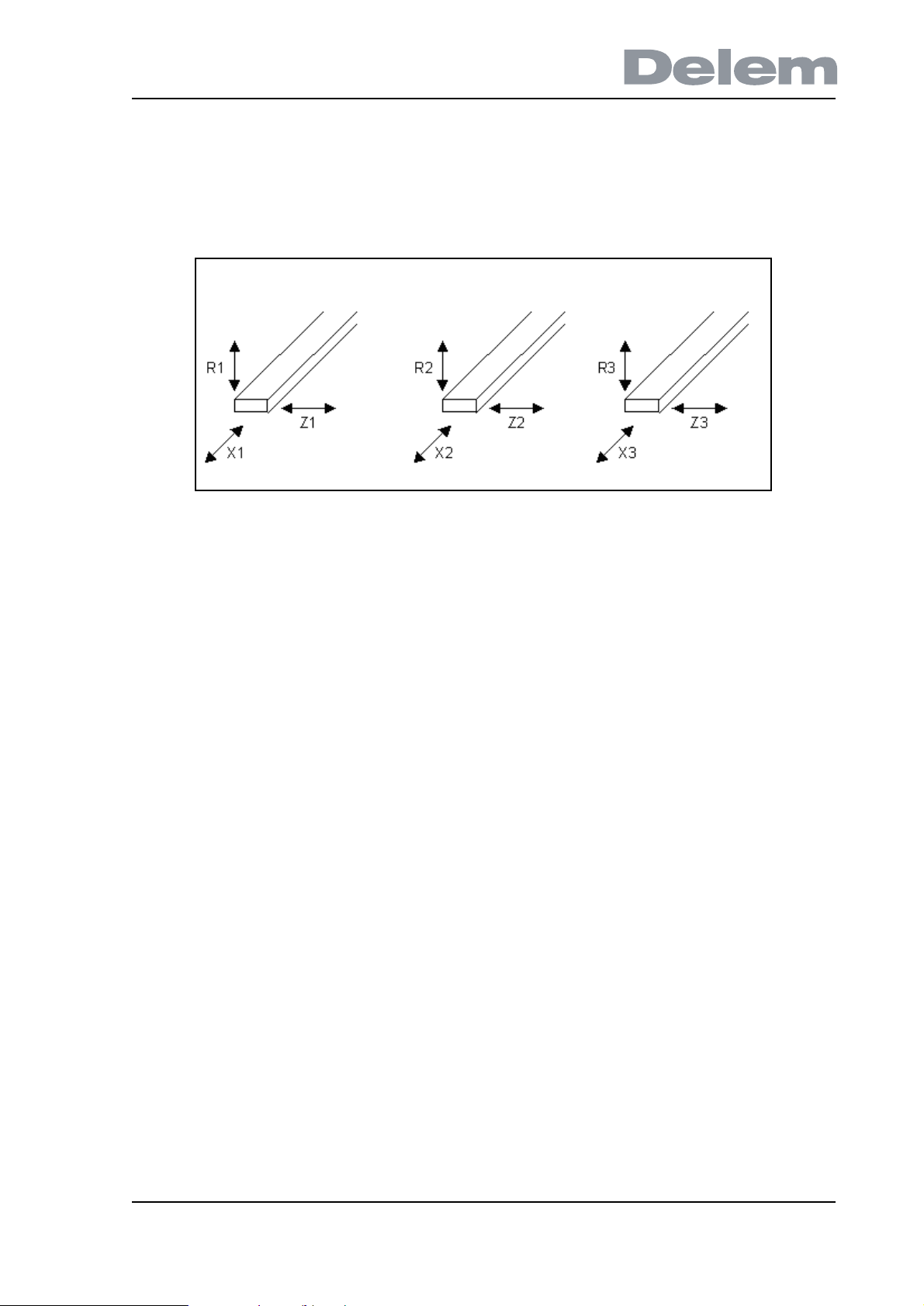
5.5. R-axis specific parameters . . . . . . . . . . . . . . . . . . . . . . . . . . . . . . . . . . . 5.11
5.6. Z-axis specific parameters . . . . . . . . . . . . . . . . . . . . . . . . . . . . . . . . . . . . 5.12
5.7. Parameters for a servo axis . . . . . . . . . . . . . . . . . . . . . . . . . . . . . . . . . . . 5.15
5.8. Parameters AC axes . . . . . . . . . . . . . . . . . . . . . . . . . . . . . . . . . . . . . . . . 5.15
5.9. X1X2 difference programming (option) . . . . . . . . . . . . . . . . . . . . . . . . . . 5.18
5.10. The spindle correction table . . . . . . . . . . . . . . . . . . . . . . . . . . . . . . . . . 5.19
6. Auxiliary axes parameters . . . . . . . . . . . . . . . . . . . . . . . . . . . . . . . . . . . . 6.1
6.1. Introduction . . . . . . . . . . . . . . . . . . . . . . . . . . . . . . . . . . . . . . . . . . . . . . . . 6.1
6.2. The General page . . . . . . . . . . . . . . . . . . . . . . . . . . . . . . . . . . . . . . . . . . . 6.1
6.3. The feedback page . . . . . . . . . . . . . . . . . . . . . . . . . . . . . . . . . . . . . . . . . . 6.9
6.4. The Control page . . . . . . . . . . . . . . . . . . . . . . . . . . . . . . . . . . . . . . . . . . . 6.21
6.5. Control fine tuning . . . . . . . . . . . . . . . . . . . . . . . . . . . . . . . . . . . . . . . . . . 6.33
6.6. The output page . . . . . . . . . . . . . . . . . . . . . . . . . . . . . . . . . . . . . . . . . . . 6.36
6.7. The safety page . . . . . . . . . . . . . . . . . . . . . . . . . . . . . . . . . . . . . . . . . . . . 6.52
7. Crowning . . . . . . . . . . . . . . . . . . . . . . . . . . . . . . . . . . . . . . . . . . . . . . . . . . 7.1
7.1. Introduction . . . . . . . . . . . . . . . . . . . . . . . . . . . . . . . . . . . . . . . . . . . . . . . . 7.1
7.2. Hydraulic crowning device . . . . . . . . . . . . . . . . . . . . . . . . . . . . . . . . . . . . . 7.2
7.2.1. Introduction . . . . . . . . . . . . . . . . . . . . . . . . . . . . . . . . . . . . . . . . . . . . . . . . . . . 7.2
7.2.2. Hydraulic crowning parameters . . . . . . . . . . . . . . . . . . . . . . . . . . . . . . . . . . . 7.3
7.2.3. Hydraulic crowning adjustment . . . . . . . . . . . . . . . . . . . . . . . . . . . . . . . . . . . 7.17
7.3. Motorised crowning AC . . . . . . . . . . . . . . . . . . . . . . . . . . . . . . . . . . . . . . 7.18
7.3.1. Introduction . . . . . . . . . . . . . . . . . . . . . . . . . . . . . . . . . . . . . . . . . . . . . . . . . . 7.18
7.3.2. Parameters AC crowning . . . . . . . . . . . . . . . . . . . . . . . . . . . . . . . . . . . . . . . 7.19
7.3.3. Crowning device adjustment for computed purposes . . . . . . . . . . . . . . . . . . 7.23
7.3.4. Crowning device adjustment for non-computed purposes . . . . . . . . . . . . . . 7.24
7.4. Dynamic crowning . . . . . . . . . . . . . . . . . . . . . . . . . . . . . . . . . . . . . . . . . . 7.25
7.4.1. Introduction . . . . . . . . . . . . . . . . . . . . . . . . . . . . . . . . . . . . . . . . . . . . . . . . . . 7.25
7.4.2. Parameters . . . . . . . . . . . . . . . . . . . . . . . . . . . . . . . . . . . . . . . . . . . . . . . . . . 7.26
7.4.3. Dynamic crowning adjustment . . . . . . . . . . . . . . . . . . . . . . . . . . . . . . . . . . . 7.28
8. Digital outputs . . . . . . . . . . . . . . . . . . . . . . . . . . . . . . . . . . . . . . . . . . . . . . 8.1
V0908, 0.4

8.1. Introduction . . . . . . . . . . . . . . . . . . . . . . . . . . . . . . . . . . . . . . . . . . . . . . . . . 8.1
8.2. Digital R-axis . . . . . . . . . . . . . . . . . . . . . . . . . . . . . . . . . . . . . . . . . . . . . . . 8.1
8.3. On/off outputs . . . . . . . . . . . . . . . . . . . . . . . . . . . . . . . . . . . . . . . . . . . . . . . 8.5
9. I-axes . . . . . . . . . . . . . . . . . . . . . . . . . . . . . . . . . . . . . . . . . . . . . . . . . . . . . 9.1
9.1. Introduction . . . . . . . . . . . . . . . . . . . . . . . . . . . . . . . . . . . . . . . . . . . . . . . . . 9.1
9.2. I-axis with 1 speed AC motor with potentiometer feedback . . . . . . . . . . . . 9.1
9.3. Digital I-axis parameters . . . . . . . . . . . . . . . . . . . . . . . . . . . . . . . . . . . . . . . 9.3
10. Part support . . . . . . . . . . . . . . . . . . . . . . . . . . . . . . . . . . . . . . . . . . . . . . 10.1
10.1. Introduction . . . . . . . . . . . . . . . . . . . . . . . . . . . . . . . . . . . . . . . . . . . . . . . 10.1
10.2. Parameters digital part support . . . . . . . . . . . . . . . . . . . . . . . . . . . . . . . 10.2
10.3. Adjustment procedures . . . . . . . . . . . . . . . . . . . . . . . . . . . . . . . . . . . . 10.28
10.4. Extra info and recommendations . . . . . . . . . . . . . . . . . . . . . . . . . . . . . 10.31
10.5. Additional part support axes . . . . . . . . . . . . . . . . . . . . . . . . . . . . . . . . . 10.34
V0908, 0.5

V0908, 0.6

Parameter index
This appendix contains a list of all
parameters described in this manual, in
alphabetic order.
Acceleration ramp . . . . . . . . . . . . . . . . .6.39
Acceleration, 0 to max. speed . . . . . . . .4.41
Acceleration, 0 to max. speed . . . . . . . .4.56
Acceleration, 0 to max. speed . . . . . . . .4.67
Acceleration, 0 to max. speed . . . . . . . .4.76
Acceleration, 0 to max. speed . . . . . . . .6.28
Adjustment mode . . . . . . . . . . . . . . . . . .10.6
AD-max . . . . . . . . . . . . . . . . . . . . . . . . .6.20
AD-max . . . . . . . . . . . . . . . . . . . . . . . . .7.21
AD-min . . . . . . . . . . . . . . . . . . . . . . . . . .6.19
AD-min . . . . . . . . . . . . . . . . . . . . . . . . . .7.20
Anti backbend dist. . . . . . . . . . . . . . . . .4.171
Automatic R-axis correction (0/1) . . . . . .7.10
Axis retract programmable . . . . . . . . . . . .6.8
Axis speed programmable . . . . . . . . . . . .6.7
Balance pressure . . . . . . . . . . . . . . . . . .4.34
Braking Ramp . . . . . . . . . . . . . . . . . . . .6.51
Braking time max . . . . . . . . . . . . . . . . .4.102
Braking time max . . . . . . . . . . . . . . . . . .4.12
Break point high speed (Bfs)< . . . . . . . .6.45
Break point high speed (Bfs)> . . . . . . . .6.43
Break point low speed (Bss)< . . . . . . . .6.44
Break point low speed (Bss)> . . . . . . . .6.42
Calibrate valves . . . . . . . . . . . . . . . . . .4.103
Calibrate valves . . . . . . . . . . . . . . . . . . .4.13
Calibration . . . . . . . . . . . . . . . . . . . . . . .4.22
Closing brake ramp . . . . . . . . . . . . . . .4.119
Closing brake ramp trim . . . . . . . . . . . .4.117
Closing gain . . . . . . . . . . . . . . . . . . . . .4.120
Closing gain trim . . . . . . . . . . . . . . . . .4.118
Closing parallelism gain . . . . . . . . . . . .4.121
Closing pressure . . . . . . . . . . . . . . . . .4.122
Closing ramp offset . . . . . . . . . . . . . . .4.115
Closing speed . . . . . . . . . . . . . . . . . . .4.112
Closing speed incr. . . . . . . . . . . . . . . .4.113
Control margin . . . . . . . . . . . . . . . . . . . .4.35
Count direction . . . . . . . . . . . . . . . . . . .4.169
Count direction . . . . . . . . . . . . . . . . . . . .6.18
Count direction left (Y1) . . . . . . . . . . . . .4.18
Count direction right (Y2) . . . . . . . . . . . .4.19
Crowning set before bending . . . . . . . . . .7.5
Crowning value . . . . . . . . . . . . . . . . . . . .7.4
DA-max . . . . . . . . . . . . . . . . . . . . . . . . .7.16
DA-min . . . . . . . . . . . . . . . . . . . . . . . . . .7.15
DA-out linear/table . . . . . . . . . . . . . . . . .7.14
Dc high speed < . . . . . . . . . . . . . . . . . . .6.48
Dc high speed > . . . . . . . . . . . . . . . . . . .6.50
Dc low speed < . . . . . . . . . . . . . . . . . . .6.47
Dc low speed > . . . . . . . . . . . . . . . . . . .6.49
Deceleration, max. speed to 0 . . . . . . . .4.42
Deceleration, max. speed to 0 . . . . . . . .4.57
Deceleration, max. speed to 0 . . . . . . . 4.68
Deceleration, max. speed to 0 . . . . . . . 4.77
Deceleration, max. speed to 0 . . . . . . . 6.29
Decimal point pos. . . . . . . . . . . . . . . . . . 6.2
Decimal point pos. . . . . . . . . . . . . . . . . . 7.6
Decompression gain . . . . . . . . . . . . . . 4.140
Decompression parallelism gain . . . . . 4.141
Decompression position offset . . . . . . 4.144
Decompression speed increment . . . . 4.143
Default value . . . . . . . . . . . . . . . . . . . . . 10.8
Default value . . . . . . . . . . . . . . . . . . . . . . 6.5
Default value . . . . . . . . . . . . . . . . . . . . . . 7.9
Default value . . . . . . . . . . . . . . . . . . . . . . 8.4
Default value . . . . . . . . . . . . . . . . . . . . . . 8.7
Del. before closing . . . . . . . . . . . . . . . 4.116
Del. before opening . . . . . . . . . . . . . . . 4.150
Delay after decompression . . . . . . . . . . 4.72
Delay at end of decompression . . . . . 4.142
Delay before closing . . . . . . . . . . . . . . . 4.47
Delay before opening . . . . . . . . . . . . . . 4.82
Delay before pressing . . . . . . . . . . . . . 4.126
Delay before pressing . . . . . . . . . . . . . . 4.63
Delay before pressing force . . . . . . . . 4.127
Delay before retour factor . . . . . . . . . . . 10.5
Die clamp pressure . . . . . . . . . . . . . . . . 3.20
Differential gain max . . . . . . . . . . . . . . 10.26
Differential gain min . . . . . . . . . . . . . . 10.25
Direction . . . . . . . . . . . . . . . . . . . . . . . . . 4.6
Direction . . . . . . . . . . . . . . . . . . . . . . . . 4.96
Direction pin up/down . . . . . . . . . . . . . . 6.41
Drive type . . . . . . . . . . . . . . . . . . . . . . . 6.25
Dwell time gain closing . . . . . . . . . . . . 4.137
Dwell time gain opening . . . . . . . . . . . 4.138
Dwell time programmable . . . . . . . . . . 4.163
Emergency deceleration time . . . . . . . . 6.30
Encoder mounted . . . . . . . . . . . . . . . . 4.166
External mute adjust . . . . . . . . . . . . . . 4.100
External mute adjust . . . . . . . . . . . . . . . 4.52
Feedforward friction value . . . . . . . . . . . 4.44
Feedforward friction value . . . . . . . . . . . 4.60
Feedforward friction value . . . . . . . . . . . 4.70
Feedforward friction value . . . . . . . . . . . 4.79
Feedforward gain max . . . . . . . . . . . . 10.24
Feedforward gain min . . . . . . . . . . . . . 10.23
Feedforward speed gain . . . . . . . . . . . . 4.45
Feedforward speed gain . . . . . . . . . . . . 4.61
Feedforward speed gain . . . . . . . . . . . . 4.71
Feedforward speed gain . . . . . . . . . . . . 4.80
Following error enabled . . . . . . . . . . . . 6.34
Following error margin . . . . . . . . . . . . . 6.35
Force maximum . . . . . . . . . . . . . . . . . . 4.24
Force Middle . . . . . . . . . . . . . . . . . . . . . 4.25
Force minimum . . . . . . . . . . . . . . . . . . . 4.26
Force programmable . . . . . . . . . . . . . . 4.164
Hysteresis . . . . . . . . . . . . . . . . . . . . . . . 7.22
Hysteresis mute-output . . . . . . . . . . . . 4.175
Hysteresis udp-output . . . . . . . . . . . . . 4.176
I-action gain . . . . . . . . . . . . . . . . . . . . 4.133
V0908, 0.7

I-gain . . . . . . . . . . . . . . . . . . . . . . . . . . 4.59
I-gain . . . . . . . . . . . . . . . . . . . . . . . . . . 6.32
In Position tolerance . . . . . . . . . . . . . . 10.7
In position tolerance . . . . . . . . . . . . . . . 6.37
Inertia under beam . . . . . . . . . . . . . . . . 3.11
Inertia upper beam . . . . . . . . . . . . . . . . 3.12
Ls FD output . . . . . . . . . . . . . . . . . . . . . 9.5
M_OPTION 1 - 64 . . . . . . . . . . . . . . . . 3.25
Machine length between cylinders . . . . 3.10
Machine name . . . . . . . . . . . . . . . . . . . . 3.8
Manual gain closing . . . . . . . . . . . . . . 4.158
Manual gain opening . . . . . . . . . . . . . 4.159
Manual parallelism gain . . . . . . . . . . . 4.160
Manual speed high . . . . . . . . . . . . . . . . . 6.6
Max. AD-value . . . . . . . . . . . . . . . . . . 10.18
Max. Angle . . . . . . . . . . . . . . . . . . . . . 10.11
Max. angle speed . . . . . . . . . . . . . . . . 10.13
Max. pressing speed . . . . . . . . . . . . . 4.125
Max. value . . . . . . . . . . . . . . . . . . . . . . . 6.4
Max. value . . . . . . . . . . . . . . . . . . . . . . . 7.8
Maximum . . . . . . . . . . . . . . . . . . . . . . . . 4.5
Maximum . . . . . . . . . . . . . . . . . . . . . . . 4.95
Maximum current . . . . . . . . . . . . . . . . . 7.13
Maximum I-action . . . . . . . . . . . . . . . . 4.134
Maximum operating speed . . . . . . . . . . 4.40
Maximum operating speed . . . . . . . . . . 4.55
Maximum operating speed . . . . . . . . . . 4.75
Maximum operating speed . . . . . . . . . . 6.27
Maximum valve pressure . . . . . . . . . . . 4.36
Maximum voltage . . . . . . . . . . . . . . . . . 7.12
Maximum Y1Y2 difference . . . . . . . . . . . 4.8
Maximum Y1Y2 difference . . . . . . . . . . 4.98
Mean angle speed high . . . . . . . . . . . 10.20
Mean angle speed low . . . . . . . . . . . . 10.19
Middle valve pressure . . . . . . . . . . . . . 4.37
Min. AD-value . . . . . . . . . . . . . . . . . . 10.17
Min. Angle . . . . . . . . . . . . . . . . . . . . . 10.10
Min. value . . . . . . . . . . . . . . . . . . . . . . . . 6.3
Min. value . . . . . . . . . . . . . . . . . . . . . . . . 7.7
Minimum . . . . . . . . . . . . . . . . . . . . . . . . 4.4
Minimum . . . . . . . . . . . . . . . . . . . . . . . 4.94
Minimum valve pressure . . . . . . . . . . . 4.38
Motor drive type . . . . . . . . . . . . . . . . . . 6.40
Mute changed tolerance . . . . . . . . . . . 4.51
Mute changed tolerance . . . . . . . . . . . 4.99
Mute programmable each step . . . . . . . 4.7
Mute programmable each step . . . . . . 4.97
Mute-2 offset . . . . . . . . . . . . . . . . . . . 4.123
Nbr positions . . . . . . . . . . . . . . . . . . . . . 9.4
Number of FD outputs . . . . . . . . . . . . . . 8.6
Number of slaves . . . . . . . . . . . . . . . . . 10.9
Offset ldp-output . . . . . . . . . . . . . . . . 4.173
Offset mute position . . . . . . . . . . . . . . . 4.49
Offset mute-2 output . . . . . . . . . . . . . . 4.50
Offset mute-output . . . . . . . . . . . . . . . 4.172
Offset udp-output . . . . . . . . . . . . . . . . 4.174
Opening brake ramp . . . . . . . . . . . . . 4.153
Opening gain . . . . . . . . . . . . . . . . . . . 4.154
Opening gain trim . . . . . . . . . . . . . . . . 4.152
Opening parallelism gain . . . . . . . . . . . 4.155
Opening pressure . . . . . . . . . . . . . . . . 4.148
Opening ramp offset . . . . . . . . . . . . . . 4.149
Opening speed . . . . . . . . . . . . . . . . . . 4.147
Opening speed above UDP . . . . . . . . . 4.10
Output for maximum speed . . . . . . . . . . 6.38
Output maximum . . . . . . . . . . . . . . . . . . 4.27
Output middle . . . . . . . . . . . . . . . . . . . . 4.28
Output minimum . . . . . . . . . . . . . . . . . . 4.29
Output type . . . . . . . . . . . . . . . . . . . . . . 7.11
Overrun . . . . . . . . . . . . . . . . . . . . . . . . . 6.23
Overrun wait time . . . . . . . . . . . . . . . . . 6.24
Parallelism gain . . . . . . . . . . . . . . . . . . . 4.46
Parallelism gain . . . . . . . . . . . . . . . . . . . 4.62
Parallelism gain . . . . . . . . . . . . . . . . . . . 4.81
Parallelity switch . . . . . . . . . . . . . . . . . 4.104
P-gain . . . . . . . . . . . . . . . . . . . . . . . . . . 4.43
P-gain . . . . . . . . . . . . . . . . . . . . . . . . . . 4.58
P-gain . . . . . . . . . . . . . . . . . . . . . . . . . . 4.69
P-gain . . . . . . . . . . . . . . . . . . . . . . . . . . 4.78
P-gain . . . . . . . . . . . . . . . . . . . . . . . . . . 6.31
Position 1...4 . . . . . . . . . . . . . . . . . . . . . . 9.7
Position measurement system . . . . . . . 6.10
Position measurement system. . . . . . . 10.14
Positioning time . . . . . . . . . . . . . . . . . . . . 9.6
Positioning tolerance . . . . . . . . . . . . . . . 4.64
Positioning tolerance . . . . . . . . . . . . . . . 6.26
Pre scaling . . . . . . . . . . . . . . . . . . . . . 4.167
Pre scaling . . . . . . . . . . . . . . . . . . . . . . 6.11
Pressing -> dwell time offset . . . . . . . . 4.132
Pressing brake ramp . . . . . . . . . . . . . . 4.129
Pressing gain . . . . . . . . . . . . . . . . . . . 4.130
Pressing gain trim . . . . . . . . . . . . . . . . 4.128
Pressing parallelism gain . . . . . . . . . . 4.131
Pressure . . . . . . . . . . . . . . . . . . . . . . . . 4.48
Pressure . . . . . . . . . . . . . . . . . . . . . . . . 4.83
Pressure at full scale of sensor . . . . . . . 4.33
Pressure balance enable . . . . . . . . . . 4.110
Pressure balance enable . . . . . . . . . . . 4.32
Pressure delay . . . . . . . . . . . . . . . . . . . 4.73
Pressure ramp . . . . . . . . . . . . . . . . . . . . 4.30
Pressure valve control type . . . . . . . . . . 4.21
Proportional gain max . . . . . . . . . . . . . 10.22
Proportional gain min . . . . . . . . . . . . . 10.21
Punch clamp pressure . . . . . . . . . . . . . 3.19
Ref. search direction . . . . . . . . . . . . . . . 6.13
Reference left (Y1) . . . . . . . . . . . . . . . . 4.16
Reference position . . . . . . . . . . . . . . . 10.16
Reference position . . . . . . . . . . . . . . . 4.168
Reference position . . . . . . . . . . . . . . . . 6.12
Reference right (Y2) . . . . . . . . . . . . . . . 4.17
Reference search speed . . . . . . . . . . . . 6.17
Relaxation Stiffness . . . . . . . . . . . . . . . 3.13
Retour movement gain . . . . . . . . . . . . 10.27
RSD switch mounted . . . . . . . . . . . . . . . 6.14
Safety direction . . . . . . . . . . . . . . . . . . . 6.53
Safety distance . . . . . . . . . . . . . . . . . . . 6.54
V0908, 0.8

Safety speed . . . . . . . . . . . . . . . . . . . . .6.55
Safety stop angle . . . . . . . . . . . . . . . . .10.12
Select KO-table . . . . . . . . . . . . . . . . . . . .3.7
Sequencer debug . . . . . . . . . . . . . . . . . .3.6
Sequencer from USB memory . . . . . . . . .3.5
Serial port 1 . . . . . . . . . . . . . . . . . . . . . .3.22
Serial port 2 . . . . . . . . . . . . . . . . . . . . . .3.23
Service row . . . . . . . . . . . . . . . . . . . . . . .3.3
Sheet follow function on/off . . . . . . . . . .10.4
Spindle allowance . . . . . . . . . . . . . . . . .6.22
Start I-action . . . . . . . . . . . . . . . . . . . . .4.135
Stiffness of frame . . . . . . . . . . . . . . . . . .3.14
Stop time . . . . . . . . . . . . . . . . . . . . . . . .6.46
Tandem . . . . . . . . . . . . . . . . . . . . . . . .4.101
Tandem . . . . . . . . . . . . . . . . . . . . . . . . .4.11
Tool Reference . . . . . . . . . . . . . . . . . . .3.16
Tool Reference correction . . . . . . . . . . .3.17
Total machine length . . . . . . . . . . . . . . . .3.9
Tracking error difference . . . . . . . . . . . .4.14
Tracking error limitation . . . . . . . . . . . . .4.53
Tracking error limitation . . . . . . . . . . . . .4.65
UDP position offset . . . . . . . . . . . . . . . .4.84
Upper beam corr. calculation . . . . . . . . .7.27
Valve deflection during delay . . . . . . . .4.145
Valve ramp closing . . . . . . . . . . . . . . . .4.114
Valve ramp opening . . . . . . . . . . . . . . .4.156
Valve scaling . . . . . . . . . . . . . . . . . . . .4.106
Y-ref search speed . . . . . . . . . . . . . . . .4.151
Y-ref search speed . . . . . . . . . . . . . . . . . .4.9
V0908, 0.9

V0908, 0.10

1. Input and output signals
1.1. Introduction
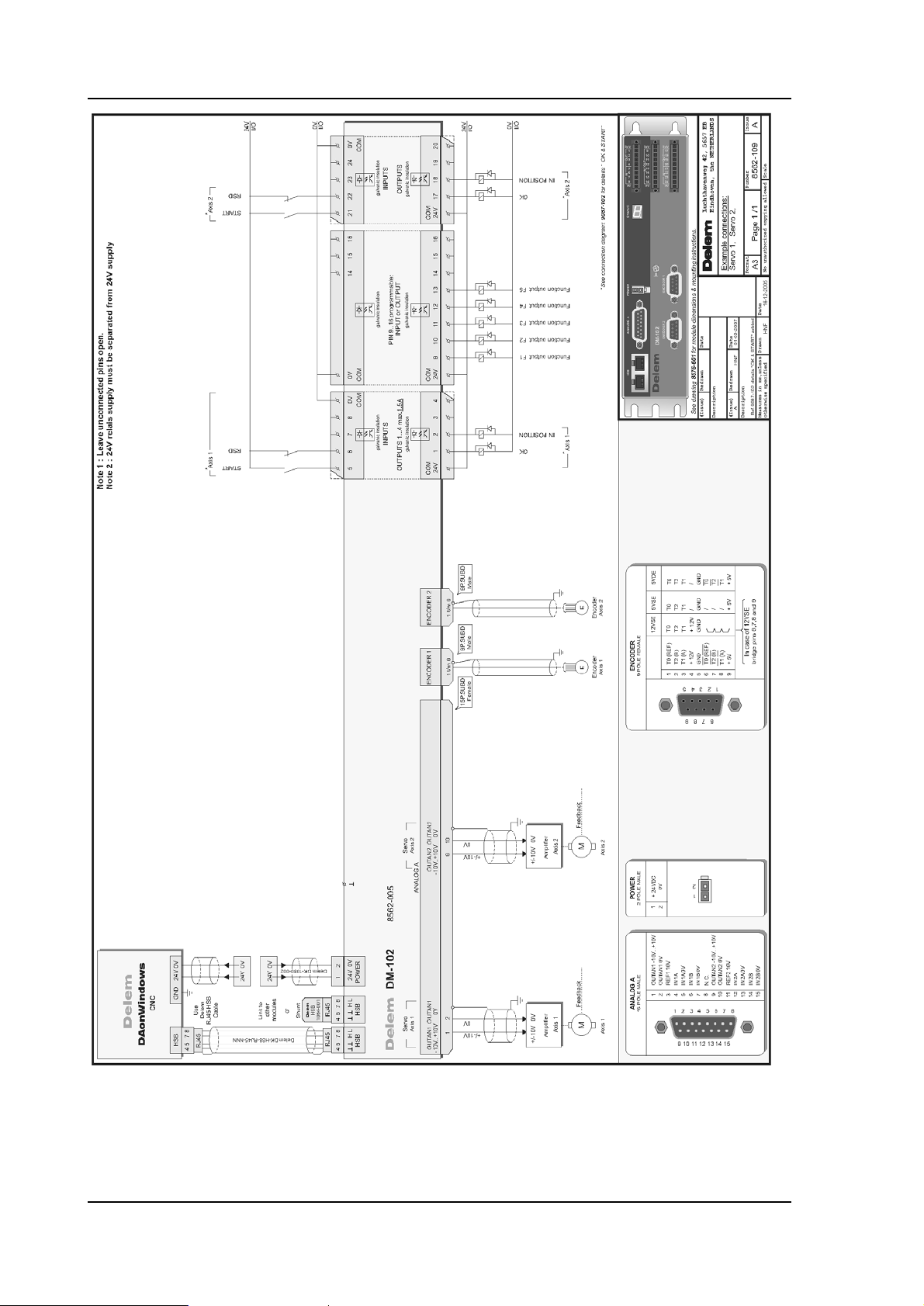
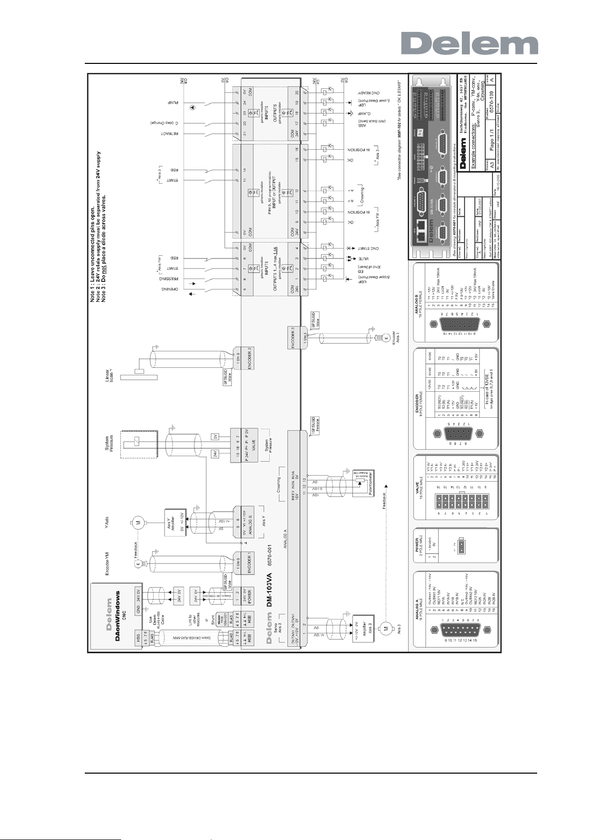
In this chapter the input and output signals of the Delem system are explained. See the
installation manual of the control for the locations of the various connectors.
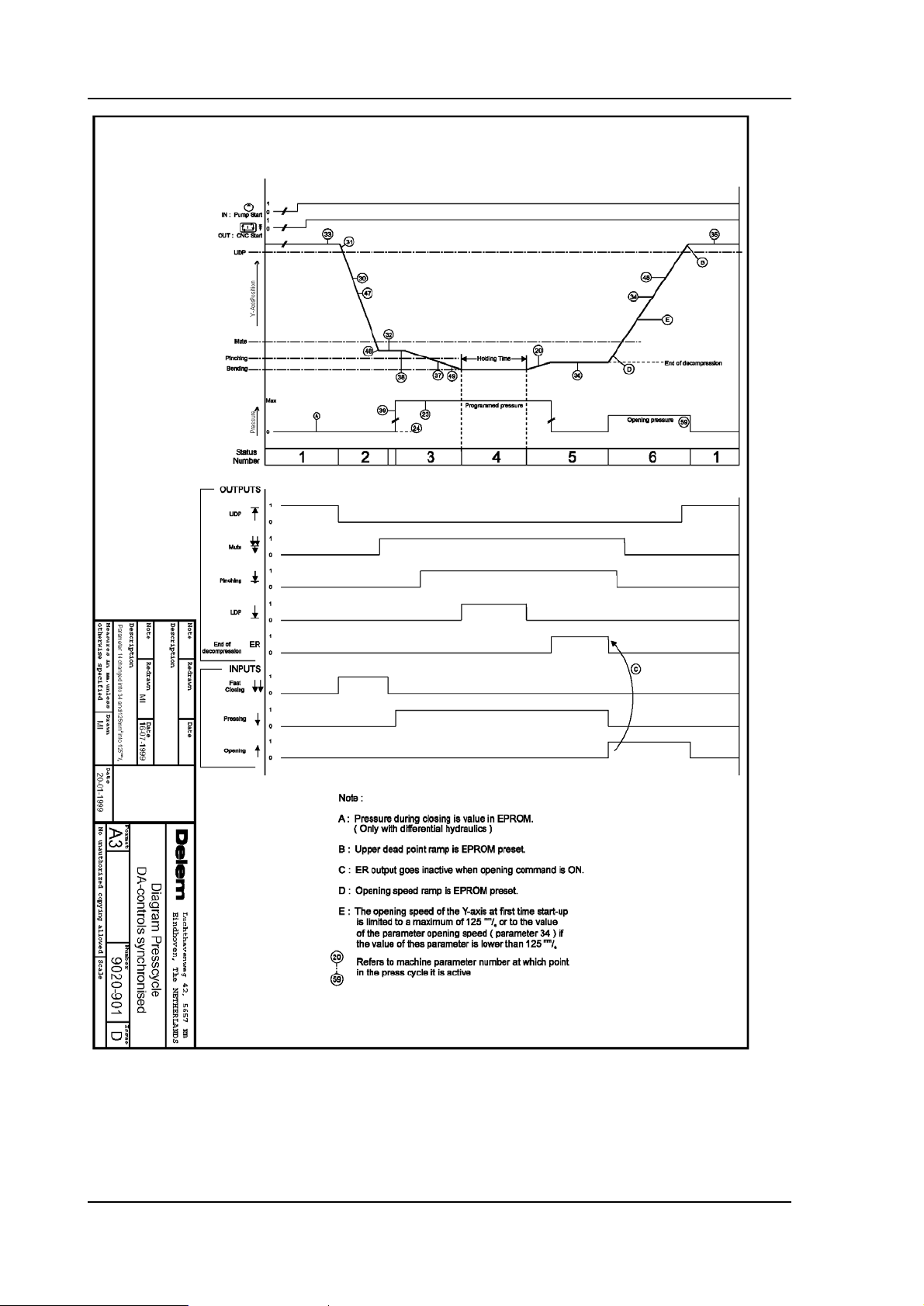
There is a strong relation between the Y-axis signals. This relation has been laid down in the
timing diagram of the press cycle.
The timing diagram of the CNC-RDY signal has also been included. This signal indicates that
the active bend program can be executed. The CNC-RDY signal depends on the status of the
start button, the position of the Y-axis and the position of the X-axis.
1.2. Y-axis input signals
Symbol Function
Opening command. This input must be active when the beam has
to move in the opening direction (Y-axis status 6).
Pressing command. This input must be active to move the press
beam during the pressing phase (Y-axis status 3). This input must
also stay active during the holding time (dwell time) at bend position
and during decompression (Y-axis status 4 and 5).
Fast closing command. This input must be active when the beam
has to move with high speed in the closing direction (Y-axis status
2).
Manual. This input must be active when the beam must be moved
manually with the handwheel. This is only possible when the control
is in Manual mode and the beam is below the mute position. When
this input is active this is displayed with the text 'adjust' in the lower
right corner of the control screen.
= Parallelism switch input. See description of Y-axis machine
parameter 'parallelism switch'.
V0908, 1.1
1.3. Y-axis output signals
Symbol Function
Upper dead point. This output is active when the beam is at the
programmed upper dead point or higher.
ER End of decompression. This output becomes active after the beam
has reached the bending position, the holding time has elapsed and
the decompression distance is completed. It goes low again
(inactive) when the opening input ( ) becomes active.
Mute output. This output becomes active when the beam reached
the muting point. This output stays active as long as the beam is
below the mute position.
CNC-started. This output is active when the start button on the DAcontrol is pressed.
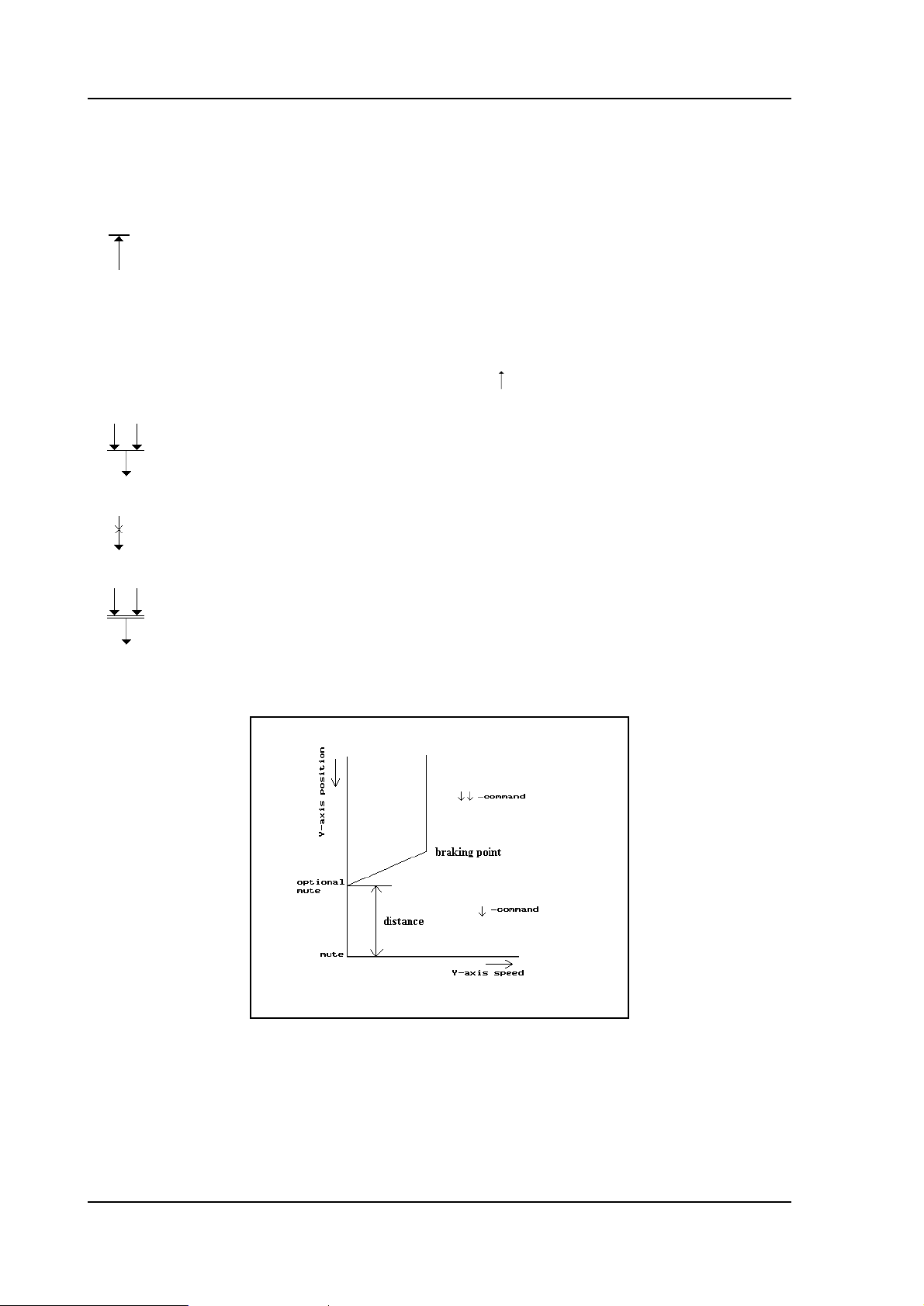
Special mute output / 2nd mute (for servo hydraulics). An optional
mute output can be used to obtain that the beam will stop more
accurate at the muting point. This feature can be useful when using
servo hydraulics. The optional mute output will be active from a
certain distance before the actual muting point.
1.a
The braking ramp for stopping at the optional muting point is computed automatically by the
control. The distance between the two muting points is programmable, the default value is 0
mm. This means that the two mute outputs become active at the same time.
V0908, 1.2
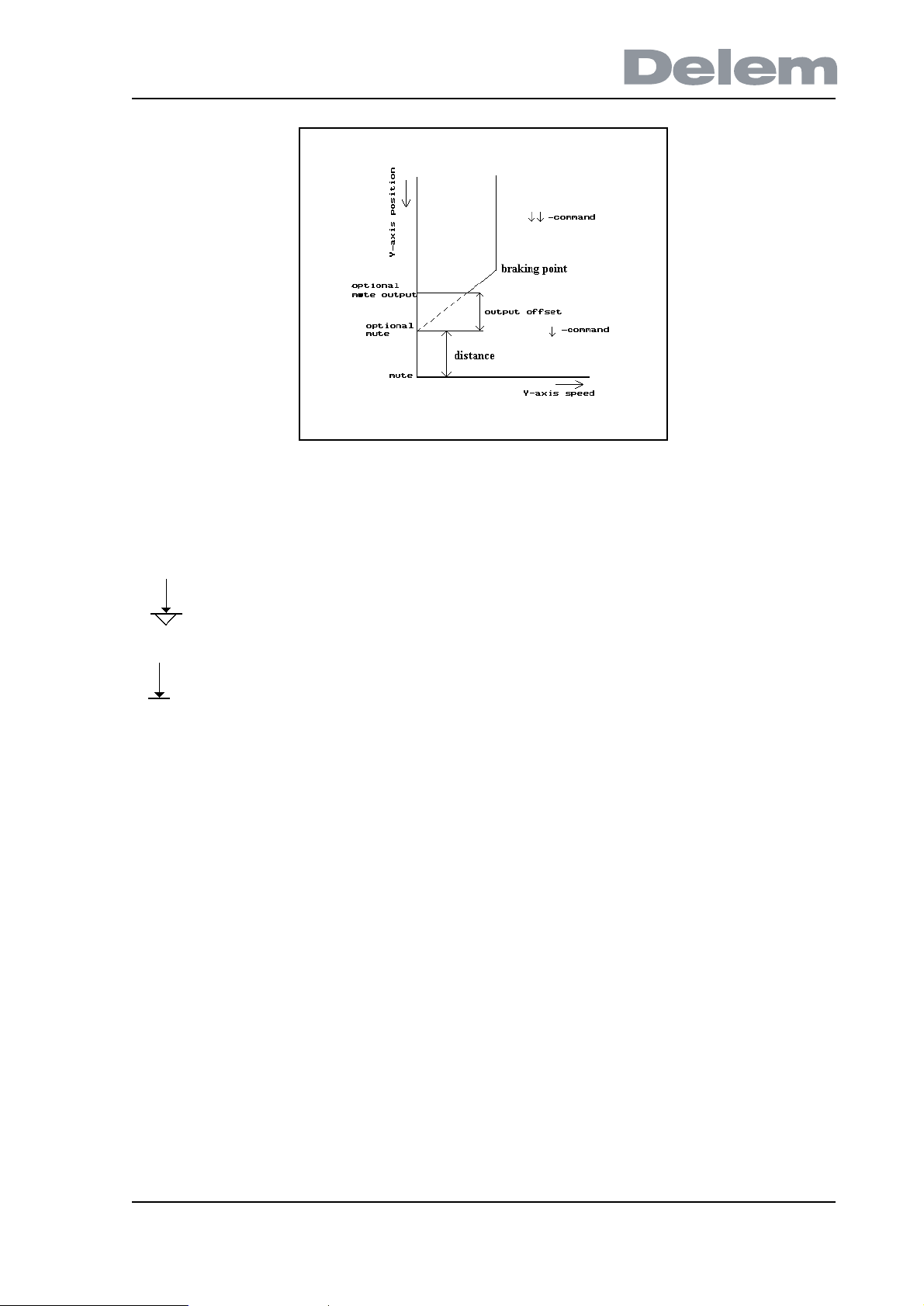
1.b
The point at which the optional mute output becomes active can also be shifted with an offset.
This offset does not shift the computed braking point. It can be programmed with the
parameter “Offset mute-2 output”. The default setting is 0.
Clamping (pinching) point output. This output becomes active when the
beam reaches the clamping (pinching) point and stays active as long as the
beam is below the clamping point.
Lower dead point output. This output becomes active at the end position of
the press beam. This output is active during Y-axis status 4.
V0908, 1.3
1.4. X-axis signals
Symbol Function
R-in R-axis positive input. This input must be active (+24V) to have the
X-axis moving within the safety zone of the applied die. Otherwise
the X-axis will not move within this zone and as a result the CNCRDY output will never become active!
When the R-axis is negative and the R-in input is active, the R-axis
will first move to a positive position before the X-axis will move to a
position within the safety zone.
1.5. Axis signals
Symbol Function
IP This output is active when the actual position value of the axis is
within the in position tolerance range of the programmed position.
This in position tolerance range can be set with the machine
parameter ‘In position tolerance’ (parameter 12).
START Input for an axis module, to signal that equipment is ready and the
module can start positioning the axis. Can be used to monitor
‘ready’ signal from a motor drive.
RSD To take the reference marker from the encoder you can connect this
input to the reference search direction switch. The reference search
cycle is then as described at the machine parameter 17 (RSDswitch). The RSD input can also be taken from an End Of Travel
switch.
1.6. Various input and output signals
V0908, 1.4

Pump started. This input must be active to be able to press the start
button on the DA-control. When this input is not active
the start button will not be accepted and the control will
display the message **machine not started**.
T Tandem input. Tandem input for tandem or robot applications. See
description of parameter 10 of the Y-axis parameters
menu. For robot applications ask for the special robot
function manual.
C Cycle input. This input can be used to realise an external step
change. This is done by programming the program
specific CX-code parameter in the programs.
CNC-START. The start command for the control. This output can only
be active (start button on control) when the pump start
input is active.
FUNCTION OUTPUTS
F1, F2, F3, F4 These are general purpose outputs. When you use a motorized
crowning unit then outputs F3 and F4 are not available, because
they are reserved for crowning usage.
CNC-RDY This output can only become active when the control is in a
production mode (automatic or step-by-step) and the following
conditions are met:
• the control has been started
• the X-axis is in position
• the beam is in the upper dead point (UDP signal is high)
• the beam is not opening (the 'open' command is not active)
• the sequencer signal C_HOLD_BEND is not active (optional,
in case sequencer is modified)
• the part support is down (optional, in case part support is
installed)
If the control is in manual mode the same conditions apply, except
in manual mode the UDP signal is not necessary for the CNC-RDY.
OK Module
initialisation
ready.
Output signal from a module, to indicate that the module is
properly initialised and is ready for action. Can be used as enable
signal to e.g. a motordrive.
V0908, 1.5
V0908, 1.6
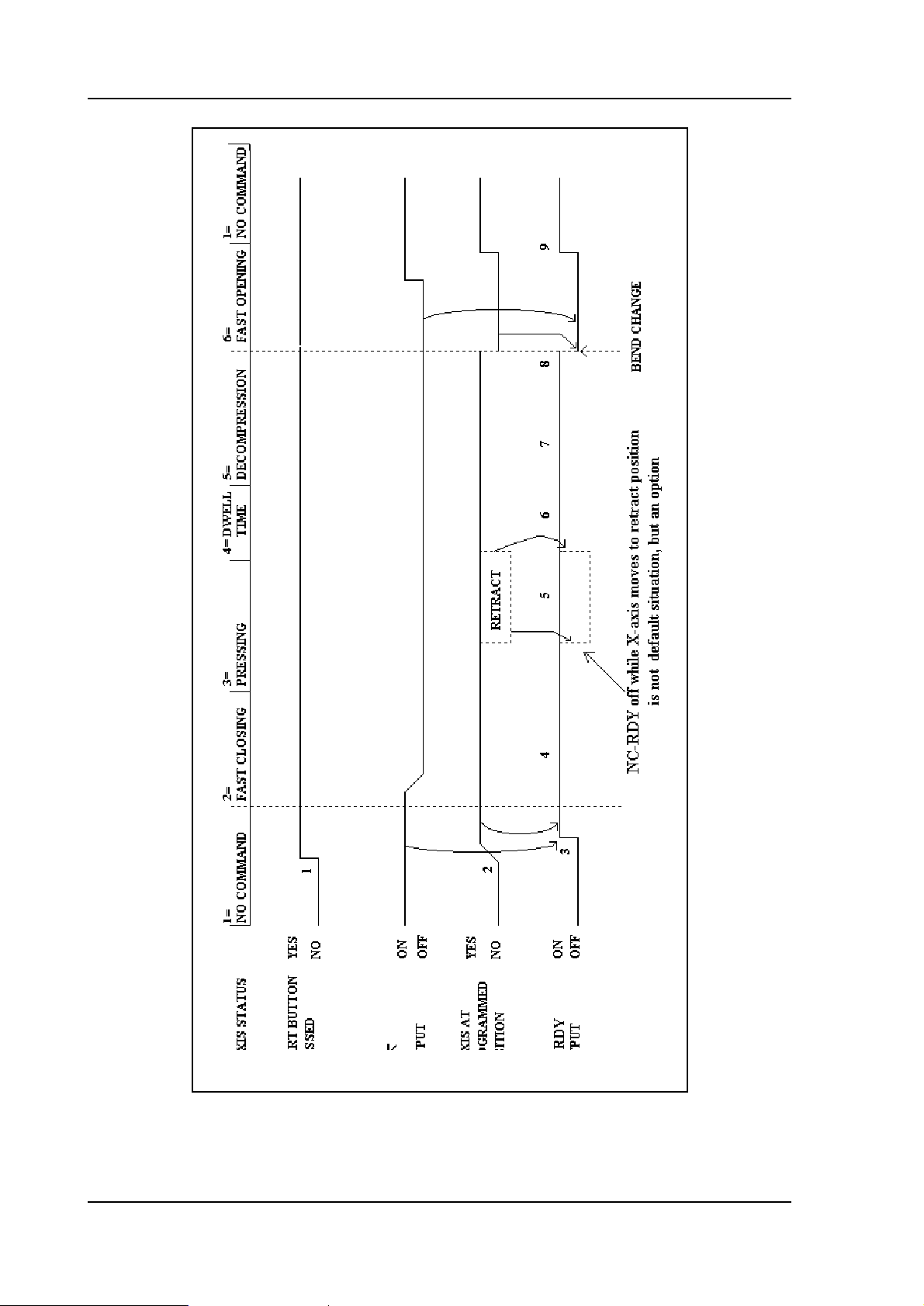
1.c

Explanation of CNC-RDY timing diagram
• Y-axis status. The Y-axis status is the number of the Y-axis control program, which
depends on the Y-axis command inputs. The number is shown on the service row (when
activated) in the header of the screen.
• Upper dead point. Y-axis output indicating that press beam is in the upper dead point
position.
• X-axis at programmed position. This line shows the actual X-axis position. This is the
same as the programmed position.
The start button must be pressed (1). When in this case the press beam is in the upper dead
point (output active) and the X-axis reaches the programmed position (2) the CNC-RDY
output becomes active (3). The CNC-RDY output stays active during fast closing of the press
beam (4), pressing (5) (when no X-axis retraction is programmed), dwell time (6) and
decompression (7).
The CNC-RDY becomes inactive after decompression of the beam (ER output active) at the
step change position where the X-axis moves to the next programmed position. Depending on
the Step change code this can take place at:
• end of decompression;
• mute (passed in opening direction);
• upper dead point.
The CNC-RDY signal becomes active again (9) when the X-axis is at its programmed position
and the Y-axis is in the upper dead point.
CNC-RDY signal during pressing with retraction programmed
There are two situations during pressing with rectraction programmed (point 5 of CNC-RDY
cyclus).
• The press beam does not wait at the pinching point for X-axis retraction to complete
(“Wait for retract” is off). The CNC-RDY output stays active while the X-axis moves to
the retract position.
• The press beam stops at the pinching point and waits until X-axis retraction is
completed (“Wait for retract” is on). The CNC-RDY output stays active while the X-axis
is moving to the retract position. The press beam moves again when the X-axis has
reached the retract position.
There is also a third situation, but this is an option.
• The press beam stops at the pinching point and waits until the X-axis rectraction has
been completed (“Wait for retract” is on). The CNC-RDY output is off while the X-axis is
moving to the retract position. The CNC-RDY output becomes active again when the Xaxis has reached the retract position.
V0908, 1.7
V0908, 1.8

V0908, 1.9
V0908, 1.10
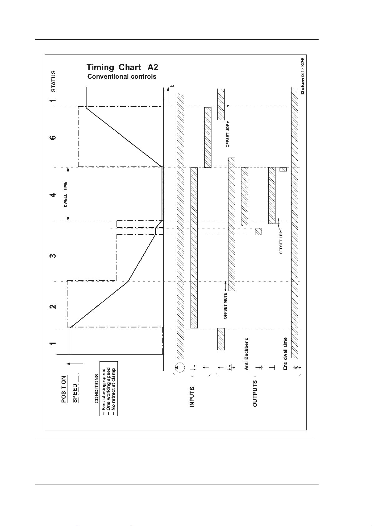
1.7. Conventional systems
Beside controls for synchronised Y-axis control, there are also Delem controls for
conventional pressbrake machines. These controls have a different set of machine
parameters for Y-axis control. The use of some parameters is related to the equipment that is
installed.
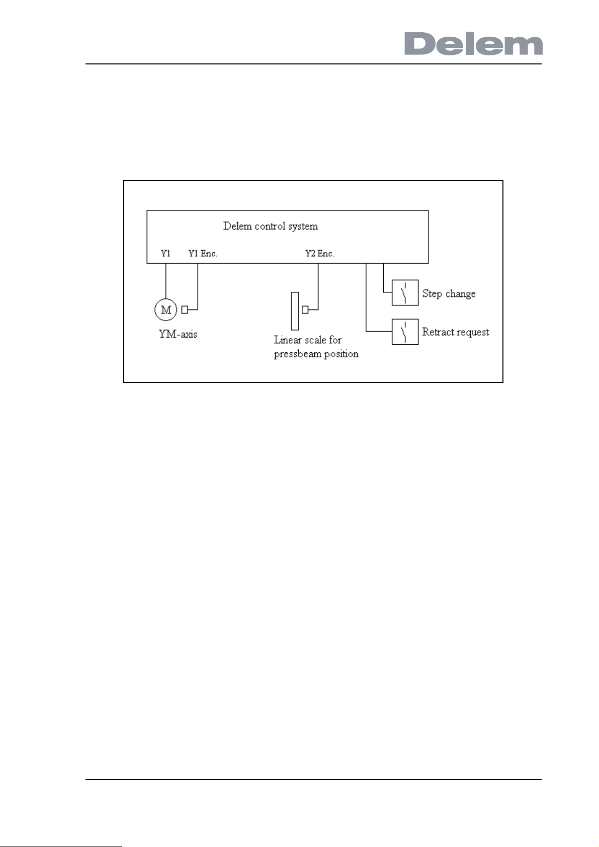
1.d
•YM-axis
A mechanical stop for the Y-axis can be programmed as an auxiliary axis (axis type YM). This
axis is controlled through the circuitry for Y1: the valve voltage output is used to control the
motor, the encoder input for Y1. The YM axis is programmed as a standard auxiliary axis. On
a DAonWindows control this auxiliary axis must be assigned to the Y-axis module. The
parameters for this axis are all standard servo parameters, which are described in chapter 5.
• Pressbeam position feedback
A conventional pressbrake machine can be equipped with a linear or rotary encoder scale for
position feedback.
If no linear scale is used, positioning of the pressbeam must be arranged externally. In that
case, a switch for 'step change' must be installed to signal to the control that a bending has
been carried out and the next step can be done. If the retract function is necessary in the
machine, a switch for a 'retract request' must be installed.
If a linear scale for position feedback is installed, these switches are not necessary. The
control can use the position information to generate a retract and a step change.
Whether or not positioning control is used is programmed with the parameter "Encoder
mounted".
See section 4.12 for more information about conventional parameters.
V0908, 1.11
V0908, 1.12
V0908, 1.13

V0908, 1.14

2. Machine parameters menu
2.1. Introduction
In this chapter the selection possibilities of the machine parameters menu are explained. The
next selection possibilities are discussed:
• selection procedure machine parameters menu (section 2.2);
• a brief introduction on the Y-axis and general parameters (section 2.3);
• a brief introduction on the auxiliary axes (section 2.5);
• notes about module configuration and module software (section 2.6);
• machine parameters backup procedure (section 2.7);
• changing the access code (section 2.8);
• viewing options (section 2.9).
2.2. Selection procedure of machine parameters menu
The selection procedure of the machine parameters menu is the same for each type of control
of the DAonWindows series.
Do the following to get access to the machine parameter menu:
• Select the programming mode.
• Enter 19 to select the machine parameter menu.
• Enter the access code.
• Press the enter key.
The default access code is 14753 for changing a basic set of machine parameters. The
machine parameters followed by (2) cannot be changed with this code. When you want to
change all the machine parameters you require the special factory code. This code may only
be used by authorised people.
There is a third access code available, which gives access to a third level of parameters.
Normally these parameters are set to factory default values and need no adjustment. In order
to view and adjust these parameters, you need to enter the menu with a level 3 access code.
You will see additional parameters, which are followed by a (3). This code may also be used
only by authorised people.
In the machine parameter main menu you also find the versions of the current KO-table and
the sequencer file. For detailed information upon the KO-table and Sequencer file version
please contact Delem.
In figure 2.a you see the main machine parameter menu of the control.
V0908, 2.1
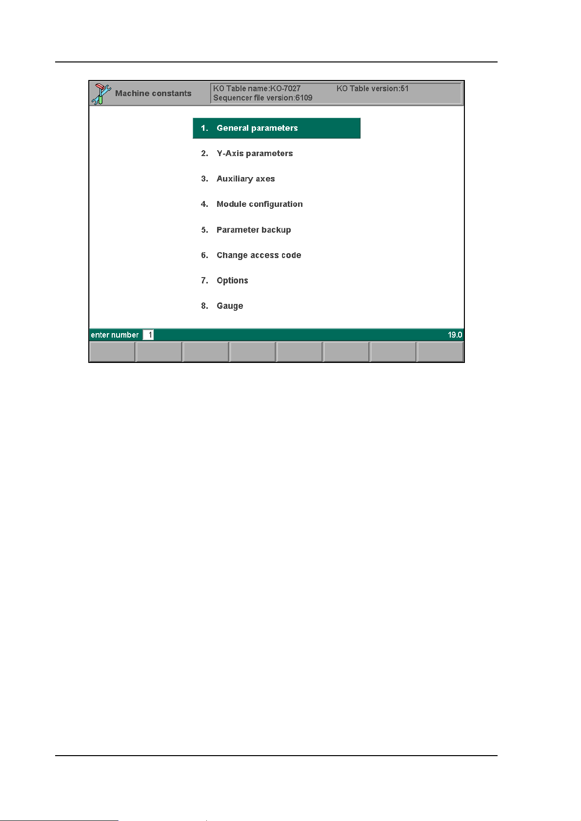
2.a
2.3. General parameters
Behind this selection possibility you find the basic machine parameters to program the press
brake specifications, such as dimensions. See chapter 3 for full explanation upon the
parameters.
2.4. Y-axis parameters
Behind this selection possibility you find the machine parameters to control the Y-axis. See
chapter 4 for full explanation upon the parameters.
2.5. Auxiliary Axes
Per type of control you can activate a number of auxiliary axes. An auxiliary axis is not active
when it is disabled in the axes menu. The required function of an auxiliary axis is determined
by the axis type.
Based on the available types the chapters 5 until 9 have been defined. In these chapters you
find explanation on the parameters in more detail.
To install auxiliary axes, three steps must be taken:
• the modules must be selected through menu 4: 'module configuration',
• the configuration of backgauges must be programmed through menu 8: 'gauge',
• the intended axes must be programmed through menu 3: 'auxiliary axes'.
See chapter 5 about auxiliary axis configuration.
2.6. Module configuration
V0908, 2.2
This function serves to select the connected modules in the system and assign the proper
axes to those modules.
Chapter 5 contains a detailed description of module configuration. This should be done first,
because otherwise no axis can be controlled.
Modules can be upgraded with new software. The procedure to upgrade a module is
explained in chapter 5.
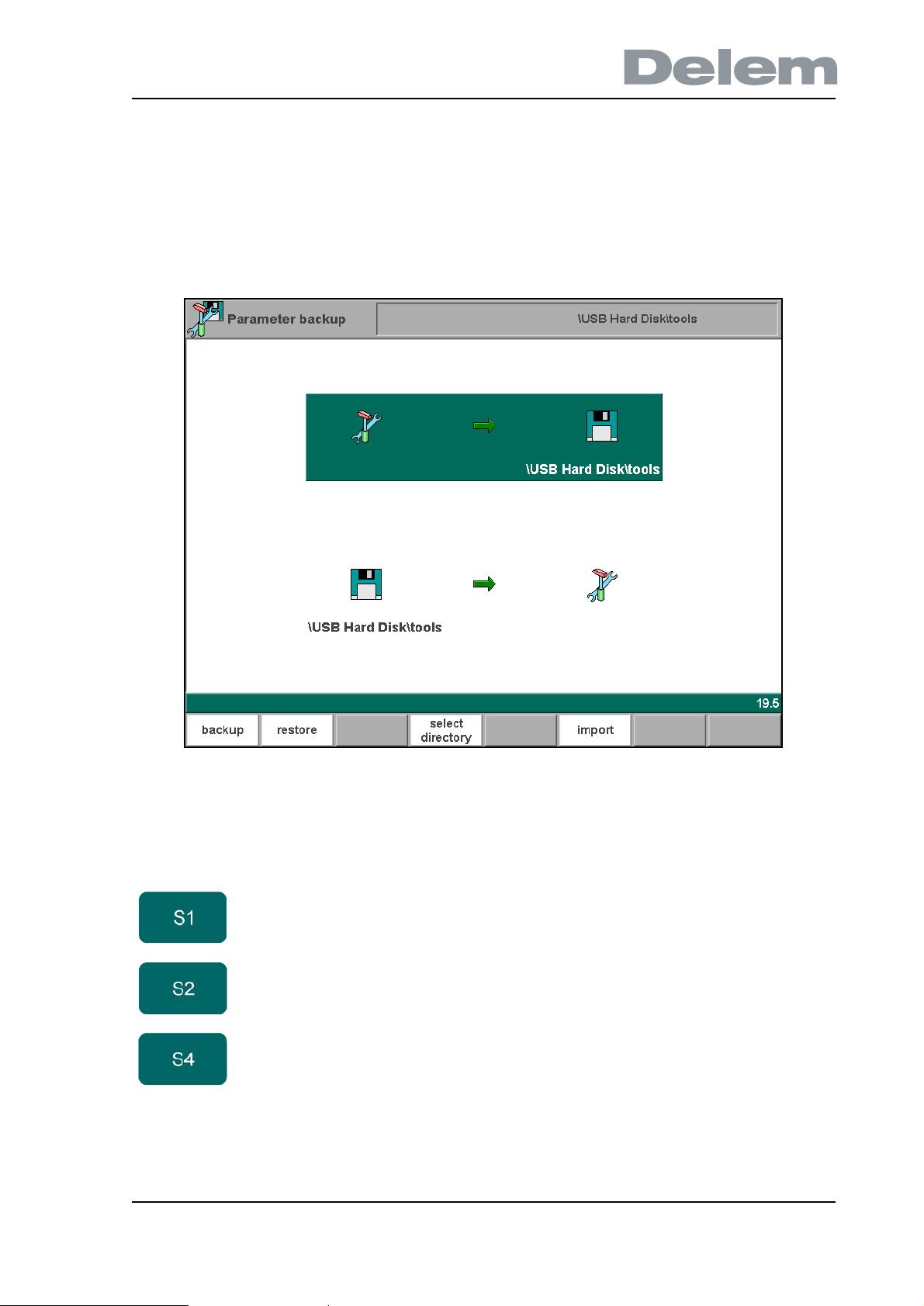
2.7. Machine parameters backup
2.b
It is very important to make a backup of the machine parameters each time they have been
changed.
Function keys:
backup To save the machine parameters to back-up location.
restore To load the machine parameters from back-up location.
select
directory
To choose the location (directory) where parameters must
be stored or read.
V0908, 2.3
2.8. Changing the access code
You can change the access code of the machine parameters menu. The procedure is as
follows:
• enter old code;
• enter new code;
• (re)enter new code;
press the enter key to accept the new value.
Without the correct access code it is impossible to enter the machine parameters menu.
Therefore, be sure if you want to change the default access code (14753).
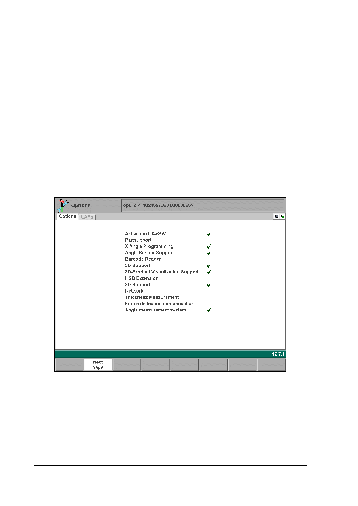
2.9. Options
The standard functionality of the Delem control can be expanded with extra options. A new
option can only be used when the option has been enabled in the control. If you wish to
activate an option, contact Delem to obtain an option voucher.
Installation of options is described in the installation manual of the DAonWindows controls.
The options with the √ - sign are already enabled in the control and can be used.
V0908, 2.4
2.c
2.10. Gauge
In this menu the configuration of backgauges and auxiliary axes must be programmed. This
programming facility offers a flexible way to describe the available backgauges and by which
axes they are moved.
2.d
See chapter 5 for information about gauge programming.
2.11. Leaving the machine parameters menu
When leaving the machine parameters menu, beware of two things.
• The control checks if all programmed axes are properly assigned to DM modules. If this
is not the case, the control issues a warning. See also chapter 5.
• If no machine parameter has been changed, the control returns to the main menu. If any
parameter has been changed, the control will reset. If ‘enter’ is pressed while the cursor
is on a machine parameter, the control will assume this parameter has been changed
and will reset itself when the menu is left.
V0908, 2.5

V0908, 2.6

3. General parameters
3.1. Introduction
In this chapter the general machine parameters are described. Each parameter explanation
comprises the following items:
• Parameter number. Each parameter has a unique number or code.
• Parameter name. Each parameter has a unique name.
• Range. The maximal value and minimal value that can be programmed.
• Default. The initial value of this parameter. This is also the value after an initialisation.
• Units. The unit of the parameter (s, mm, kg, DA-points, etcetera).
• Function. The function of the parameter.
• Description. Full description of the use and meaning of the parameter.
Standard all parameters are valid for all controls mentioned in this manual. If there are
exceptions then this is indicated.
V0908, 3.1
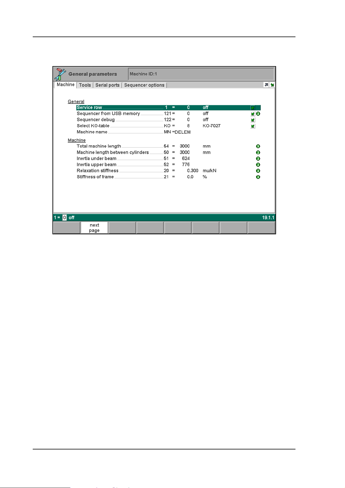
3.2. The Machine page
3.a
V0908, 3.2

Parameter: 1
Service row
Range : 0-1
Default : 0
Units : -
Function
To display the actual Y-axis linear scale readings, status and cycle numbers on the screen.
There are two possibilities:
1 = Service row present
0 = Service row not present
Press the key to select the required setting.
Description
The service row is displayed on the upper row of the screen. When switched on the actual Yaxis linear scale readings, the status and cycle numbers are displayed on the screen.
On the control the following line is displayed.
Y1 = 123.15 Y2 = 123.21 status= 1 cyclus = 0 Idle
The service row contains 5 information fields:
Y1 = left side linear scale reading
Y2 = right side linear scale reading
Status = status number
Cyclus = cycle number
Idle = communication information
The fields status, cyclus and communication information can have several values:
The status number gives information about the Y-axes servo valve control.
1 = no valve control
2 = fast closing
3 = pressing (working stroke)
4 = holding at bending position
5 = decompression
6 = fast opening
7 = manual positioning mode
8 = reference opening Y-axis (not for KO-table 7xxx)
9 = reference closing Y-axis (not for KO-table 7xxx)
The cyclus number gives information about the backgauge status.
0 = No movement control of X-axis
-1 = Manual mode
-2 = Control waits until auxiliary axes have passed reference
1 = Control waits until backgauge is in position, the beam is in UDP, and the opening
command is released
2 = Control waits until beam is at muting
3 = Control waits until beam is at clamping point
4 = Control waits until retract of backgauge is completed
V0908, 3.3

5 = Control waits until beam is at bending position, and decompression is completed
6 = Control waits until beam is at muting point after bending (in opening direction of beam)
7 = Control waits until upperbeam has moved from muting to UDP in opening direction
8 = Control waits in UDP until dwell time in UDP has been expired.
11 = Wait until beam is in UDP in case of step-by-step mode when no auto-step-change is
selected.
12 = Waiting for C-input active in case step-change code CX = 4 or 5 is selected.
14 = Clamp is active, waiting until retract is finished.
20 = Waiting until all axes have been started.
50 = Sequencer functions are being excuted.
Note:
When an optional second servo axis is enabled, this will have consequences for cycle
numbers -2, and -1:
-2 = Control waits until X-axis and second servo-axis references are passed. (e.g. X2- or Raxis)
-1 = Control waits until X-axis and second servo axis are both in position, the beam is in UPD
and the opening command is released.
When the second servo axis is configured as X2-axis also cycle number 4 is affected.
4 = Control waits until retraction of X-axis and X2-axis are both completed.
V0908, 3.4

Parameter: 121
Sequencer from USB memory
Range : 0 - 1
Default : 0
Units : -
Function
To read the sequencer file from an external USB device.
Description
During the development and testing of the sequencer file, it can be useful to read this file from
an external device, without having to modify the existing application. This possibility can be
selected by adjusting this machine parameter.
0 = using sequencer file from the internal application
1 = loading sequencer file from external USB device
Press the key to select the required setting.
With this parameter set to 1 the sequencer file is only read from USB disk during start up.
After testing the sequencer file you should set this parameter to 0 again. Put all required
sequencer files on the hard disk of the control and restart the control.
Note:
For more information about working with the sequencer file please refer to the sequencer
manual. This manual can be requested at Delem.
V0908, 3.5

Parameter: 122
Sequencer debug
Range : 0 - 1
Default : 0
Units : -
Function
To activate the sequencer debug facility. Press the key to select the required setting.
Description
When the sequencer debug facility has been switched on (=1) a soft key appears in the
manual mode. Activating this key will generate a test row on top of the screen. In this row you
can check the equations of the sequencer. This test row overwrites the service row (in case
the service row is active).
See also the Delem Sequencer manual for more information.
V0908, 3.6

Parameter: KO
Select KO-table
Range : Default : -
Units : -
Function
To choose the desired KO-table with machine settings. Press the key to select the required
setting.
Description
With this parameter the desired KO-table is selected. When activated, a pop-up list is offered
with a list of available KO-tables. The list will show all KO-table files that are present on the
control disk.
V0908, 3.7

Parameter: MN
Machine name
Range : Default : -
Units : -
Function
Name or description of the current machine. The maximum length is 25 characters.
V0908, 3.8

Parameter: 54
Total machine length
Range : 0 - 15000
Default : 2000
Units : mm
Function
Total machine length for check in relation with the product length.
Description
When the operator programs a bending length longer than the programmed total machine
length a warning appears on the screen.
V0908, 3.9

Parameter: 50
Machine length between cylinders
Range : 0 - 15000
Default : 2000
Units : mm
Function
The length of machine table between the cylinders will be used to compute the table
deflection.
Description
This parameter is used to compute the machine table deflection. The table deflection is only
computed when a crowning adjustment device is connected. (See chapter 6).
You have to program the machine length between the mid position of the 2 cylinders. See also
machine parameters ‘Inertia under beam’, and ‘Inertia upper beam’.
3.b
V0908, 3.10

Parameter: 51
Inertia under beam
Range : 0 - 99999
Default : 624
Units : 1000 cm
Function
The inertia of the machine table is used to compute table deflection.
Description
This parameter is used to compute the machine table deflection. The table deflection is only
computed when a crowning adjustment device is connected (see chapter 6).
See also machine parameters ‘Machine length between the cylinders’ and ‘Inertia upper
beam’.
Example
Inertia = 1349000
Program: 1349
4
V0908, 3.11

Parameter: 52
Inertia upper beam
Range : 0 - 99999
Default : 776
Units : 1000 cm
Function
The inertia of the machine upper beam is used to compute table deflection.
Description
This parameter is used to compute the machine table deflection. The table deflection is only
computed when a crowning adjustment device is connected. (See chapter 6).
See also machine parameters ‘Inertia under beam’ and ‘Machine length between the
cylinders’.
Example
Inertia = 1349000
Program: 1349
4
V0908, 3.12

Parameter: 20
Relaxation Stiffness
Range : 0.000-99.900
Default : 0.300
Units : µm/kN
Function
Stiffness of frame used to compute decompression.
Description
The stiffness of the frame is used to compute the decompression distance. This value will be
multiplied with computed force to obtain decompression distance.
V0908, 3.13

Parameter: 21
Stiffness of frame
Range : 0.0-100.0
Default : 0.0
Units : %
Function
Stiffness of frame, used for Y-axis depth computation.
Description
When you program bending angles, the corresponding bending depth is computed
automatically. Stiffness of frame is used to compute a correction for this bending depth due to
the deflection of the frame.
The deflection compensation arm will not fully compensate the deflection of the side frame in
order to compensate the Y-axis bend position. Bending the same metal with length of 0,5
meter must have the same angle when bending it with a length of 1 meter or longer.
The difference between the two bends is the tonnage. With 1 meter length the frame will
deflect more because it requires more tonnage when bending 0,5 meter.
The value programmed for this parameter must be the deflection of the side frame which is
not compensated by the compensation arm. This value is programmed as a percentage of the
value programmed for the machine parameter ‘Relaxation Stiffness’.
V0908, 3.14
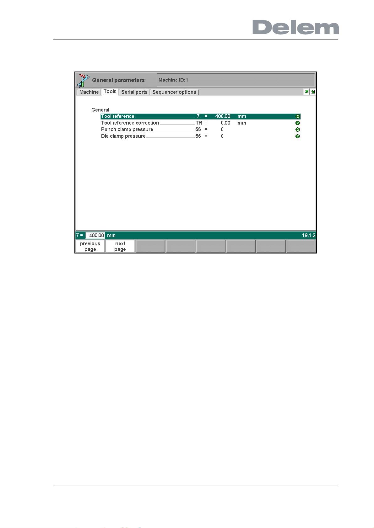
3.3. Tools page
3.c
V0908, 3.15
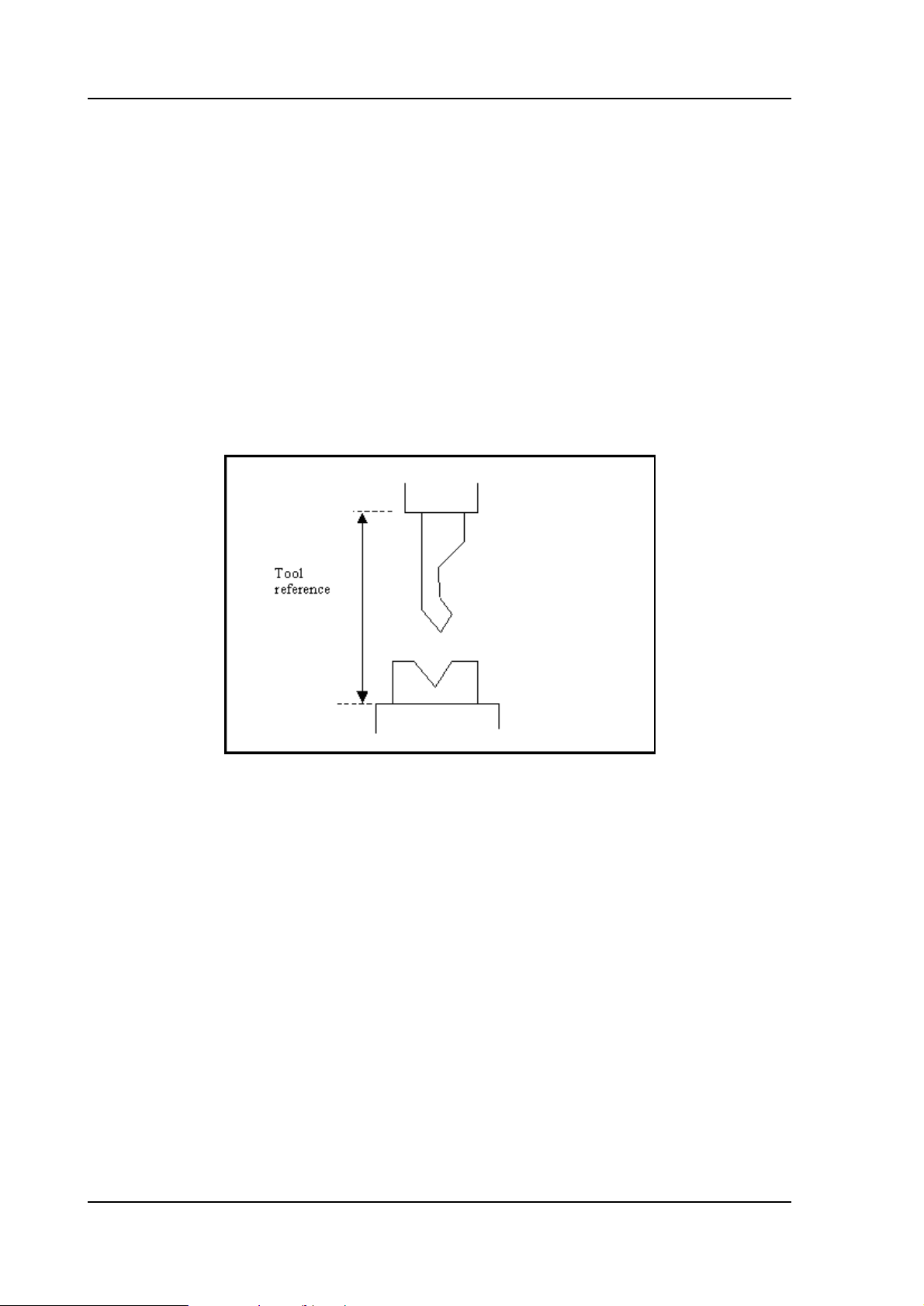
Parameter: 7
Tool Reference
Range : 0.00-9999.99
Default : 320.00
Units : mm
Function
The machine opening between upper beam and table.
Description
This is the opening between upper beam and table when the Y-axis is at zero. This value is
used in the computation of the bending depth, mute point and clamping point.
3.d
V0908, 3.16

Parameter: TR
Tool Reference correction
Range : 0.00-9.99
Default : 0.00
Units : mm
Function
A correction of the Tool Reference value for head mounted punches.
Description
The control can make a distinction between ‘head mounted’ punches and ‘shoulder mounted’
punches.
In case of a shoulder mounted punch (default situation), the control uses the Tool reference
and the Tool height to compute the correct Y-axis position. Since the Tool height is measured
from the punch’ shoulder, this leads to accurate positioning.
In case of head mounted punches, the punch’ shoulder might not correspond with the lower
edge of the pressbeam. In that case, the position of the Y-axis is no longer accurate.
3.e
In such case, a correction of the Tool Reference value can be programmed.
The Tool reference correction is only taken into account, when a head mounted punch is used
in a bend program. Otherwise, it is ignored. The type of punch can be programmed at the
punch parameters in programming mode:
V0908, 3.17
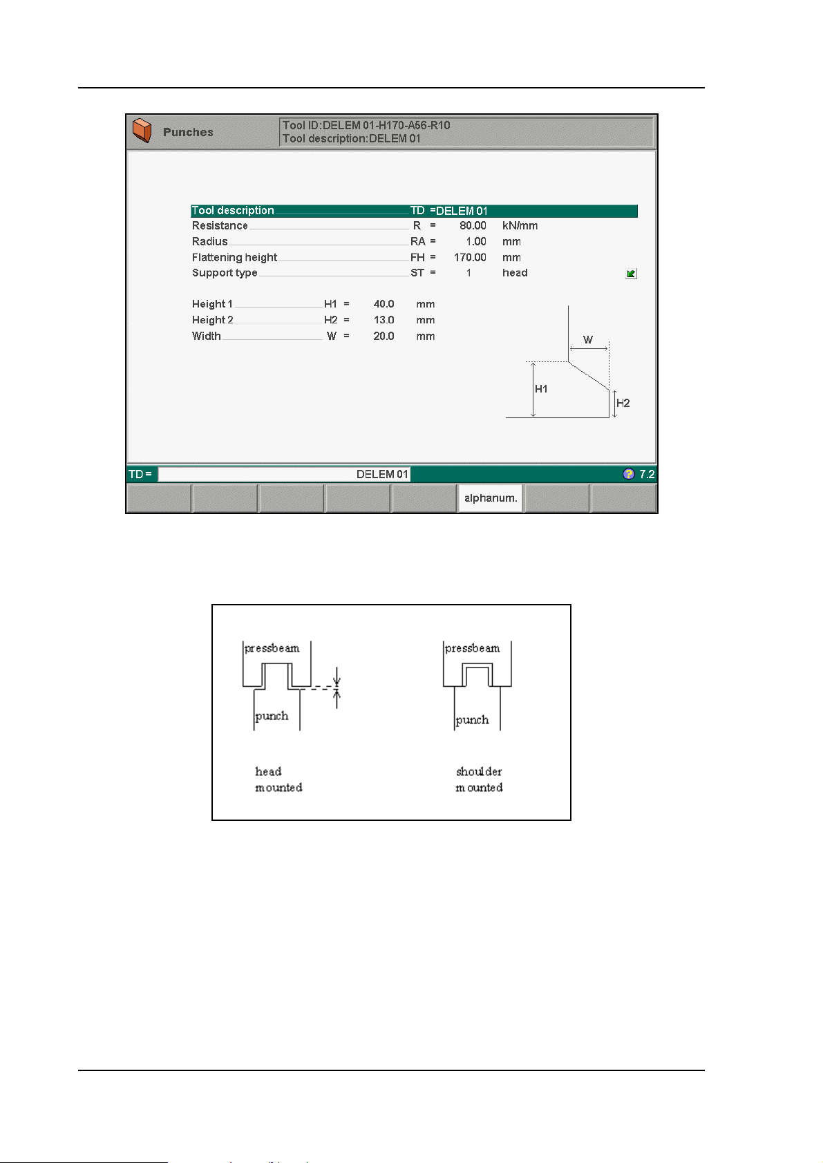
0 = shoulder mounted (default)
1 = head mounted
3.f
3.g
V0908, 3.18

Parameter: 55
Punch clamp pressure
Range : 0-255
Default : 0
Units : DA-points
Function
Pressure setting for correct punch clamping.
Description
It is possible to control the pressure valve output for the hydraulic system, specifically meant
for the punch-clamp application. This can only be achieved by means of the sequencer file.
Note:
For more information about working with the sequencer file please refer to the sequencer
manual. This manual can be requested at Delem.
V0908, 3.19

Parameter: 56
Die clamp pressure
Range : 0-255
Default : 0
Units : DA-points
Function
Pressure setting for correct die clamping.
Description
It is possible to control the pressure valve output for the hydraulic system, specifically meant
for the die clamp application. This can only be achieved by means of the sequencer file.
Note:
For more information about working with the sequencer file please refer to the sequencer
manual. This manual can be requested at Delem.
V0908, 3.20
3.4. Serial ports page
3.h
V0908, 3.21

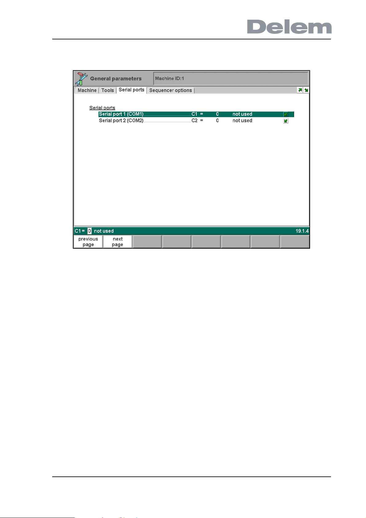
Parameter: C1
Serial port 1
Range : Default : Not used
Units : -
Function
To select a function for this serial port.
Description
The serial port can be used for communication with external devices. Such a device can be a
PLC, safety PLC or an angle measurement system. The following possibilities are supported:
• Pilz PCSS
• Pilz PnozMulti
• Lazersafe PCSS
• Fiessler FPSC
• Protractor
If a device is connected, the control and the device can exchange status information or press
commands across the serial connection.
V0908, 3.22

Parameter: C2
Serial port 2
Range : Default : Not used
Units : -
Function
To select a function for this serial port.
Description
Please refer to the description of “Serial port 1”.
V0908, 3.23
3.5. Sequencer page
3.i
V0908, 3.24

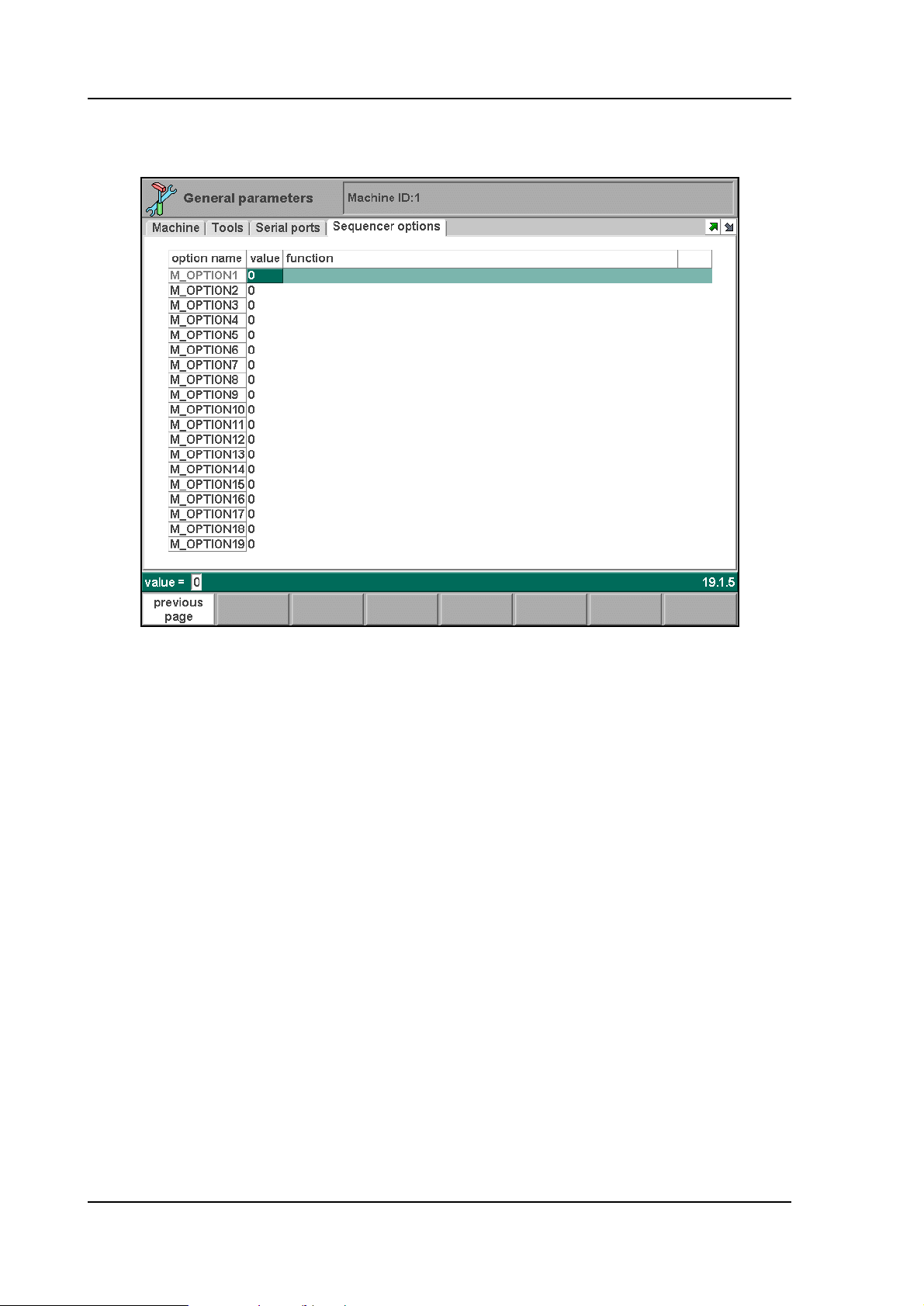
Parameter: M_OPTION
M_OPTION 1 - 64
Range : 0 - 1
Default : 0
Units : -
Function
To set general purpose sequencer option flags.
Description
These parameters are sequencer option flags. There are 64 sequencer flags available for
programming. Each flag can have the value 0 or 1. By using these flags in the sequencer, the
behaviour of the sequencer can be altered by programming these parameters.
Beside each flag, it is possible to enter comment about this flag, in the column named
‘function’. The maximum allowed length is 35 characters.
Note 1
If you are using the standard Delem sequencer and have not
then these parameters have no function.
created your own sequencer,
Note 2
For more information about working with the sequencer file please refer to the sequencer
manual. This manual can be requested at Delem.
V0908, 3.25

V0908, 3.26

4. Y-axis parameters
4.1. Introduction
In this chapter the parameters of the Y-axis are described. Each parameter explanation
comprises the following items:
• Parameter number. Each parameter has a unique number or code.
• Parameter name. Each parameter has a unique name.
• Range. The maximal value and minimal value that can be programmed.
• Default. The initial value of this parameter. This is also the value after an initialisation.
• Units. The unit of the parameter (s, mm, kg, DA-points, etcetera).
• Function. The function of the parameter.
• Description. Full description of the use and meaning of the parameter.
Standard all parameters are valid for all controls mentioned in this manual. If there are
exceptions then this is indicated.
The parameters are divided across several screens. These screens are ordered according to
the chronological order of a Y-axis cycle.
Parameters with the indication (2) behind the name are always visible, but they can only be
edited when you have entered the level 2 access code.
Parameters with the indication (3) behind the name are only accessible when a level 3 acces
code has been entered. If no level 3 access code has been entered, they remain invisible. It
will be indicated in this manual if parameters require level 3.
V0908, 4.1

4.2. Parameters for a KO-table in the 7000-range
4.2.1. Introduction
In this section the Y-axis parameters are described for synchronised Y-axis control. These
parameters appear if a KO-table is selected with a number between 7000 and 7999. The
number of the active KO-table is shown in the main menu of the machine parameters. To
change the selected KO-table, go to the General parameters and to the parameter ‘Select
KO-table’.
V0908, 4.2
4.2.2. The General page
4.a
V0908, 4.3

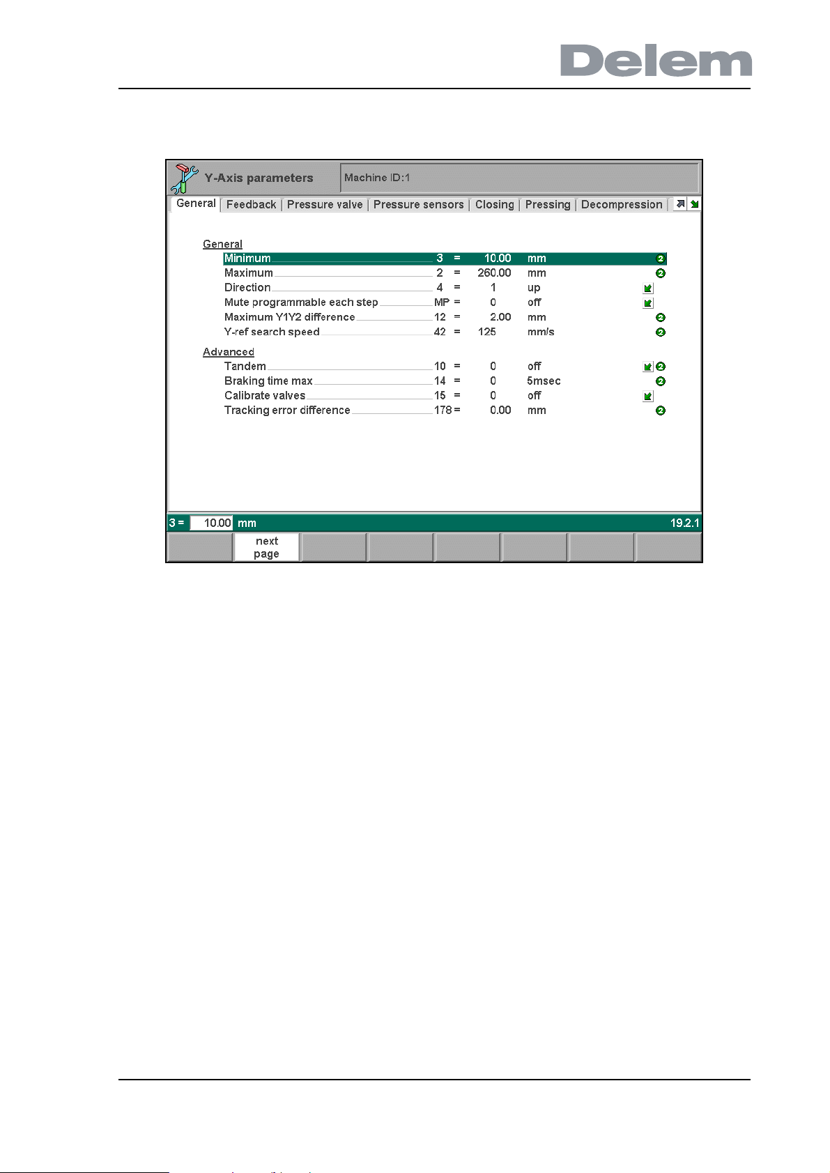
Parameter: 3
Minimum
Range : 0.00-9999.99
Default : 10.00
Units : mm
Function
Minimal Y-axis value
Description
The minimum position the beam can be moved to. This value is used as a soft limit. When the
start button on the control is pressed the control checks all Y-axis parameters, which are
programmed or computed. If a programmed or computed Y-axis value is smaller than Y-min
the value is limited at the Y-min value and the following error message appears on the screen.
** Y-axis << limit **
There are the following causes possible for this error message:
- programmed or computed bending position < Y-min
- programmed or computed mute point < Y-min
- computed clamping point < Y-min
Note
This programmed minimum position should be below the mechanical top dead centre, to
make sure this position can always be reached. For example, when the beam is in the
mechanical top dead centre and the Y-axis value is 5 mm, Y-min must be bigger than 5 mm.
V0908, 4.4

Parameter: 2
Maximum
Range : 0.00 - 9999.99
Default : 150.00
Units : mm
Function
Maximal Y-axis value
Description
The maximum position the beam can be moved to. This value is used as a soft limit.When the
start button on the control is pressed, the control checks all Y-axis parameters, which are
programmed or computed. If a programmed or computed Y-axis value is greater than Y-max
the value is limited at the Y-max value and the following error message appears on the
screen:
** Y-axis >>limit **
The following causes for this error message are possible:
- programmed or computed bending position >Y- max
- programmed or computed mute point > Y-max
- computed clamping point > Y-max
V0908, 4.5
Parameter: 4
Direction
Range : 0-1
Default : 1
Units : -
Function
Y-axis counting direction
Description
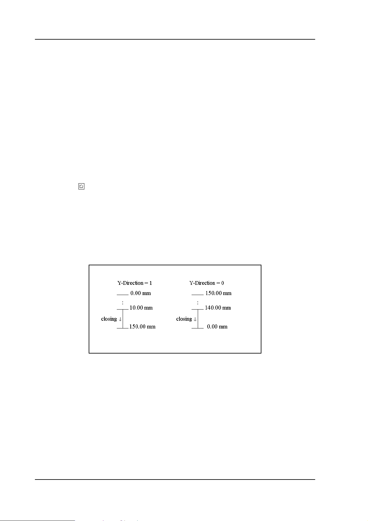
When you have programmed ‘1', the Y-axis value on the user screen counts up when the
beam closes. When you have programmed ‘0', the Y-axis value on the user screen counts
down when the beam closes.
Press the key to select the required setting.
Note
The definition of all the Y-axis machine parameters such as ‘Y-max’ and ‘Y-min’ is always in
the count up direction.
Example
Y-max = 150.00 mm
Y-min = 10.00 mm
4.b
V0908, 4.6

Parameter: MP
Mute programmable each step
Range : 0-1
Default : 0
Units : -
Function
Enable or disable the mute parameter for the operator in the data edit mode.
Description
In the standard situation (OFF), the mute point for each bend is calculated from the mute
distance of the die. In some situations, it is desired that the operator can change the mute
point for a bend. When this parameter is switched ON, the mute point can be changed for
each individual bend of a program.
Press the key to select the required setting.
V0908, 4.7

Parameter: 12
Maximum Y1Y2 difference
Range : 0.00-50.00
Default : 2.00
Units : mm
Function
Maximum allowed difference between Y1 and Y2.
Description
This parameter is the maximum allowed difference between the left beam position (Y1) and
the right beam position (Y2). For the control there are two parameters that influence the beam
parallelism:
1. Parallelism programmable under the programming constants. This value has effect over
the entire stroke of the beam.
2. Parallelism programmable in data preparation, data editing and manual mode. This
value is taken into account when the beam reaches the clamping point and stays active until
the opening command ( ) becomes active.
The total parallelism is the sum of the values described under 1 and 2. When in automatic
mode a total parallelism that is greater than the max. parallelism is detected the control goes
to stop and the following warning is displayed on the screen:
** Parallelism > max. parallelism **
V0908, 4.8

Parameter: 42
Y-ref search speed
Range : 10.0 - 250.0
Default : 125.0
Units : mm/s
Function
Setting of the Y-axis speed during reference search.
Description
This is the speed with which the beam is controlled in the upward direction during the
reference search cycle.
When the reference search cycle of he Y-axis is started, the beam is controlled in the upward
direction with the speed which is programmed here. The sequence of the complete reference
cycle depends on the position of the beam:
• if the beam was positioned below the reference point, the Y-axis will reach the reference
point and set the position;
• if the beam was positioned above the reference point, the beam will also move upwards
with the programmed speed. When the beam reaches the mechanical upper dead point,
the control will detect after a short period that there is no movement and will activate the
UDP output. As soon as a closing command is generated, the beam is controlled
downwards with closing speed (parameter 30). The beam should now find reference.
V0908, 4.9

Parameter: 24 (level 3)
Opening speed above UDP
Range : 5 - 100
Default : 5
Units : mm/s
Function
Program an opening speed above upper dead point (UDP).
Description
Program an opening speed in case the beam is moved up while it is above upper dead point
(UDP). This is possible, for instance, when the beam has been stopped after a bend step and
a separate opening command is generated to move the beam up.
V0908, 4.10

Parameter: 10
Tandem
Range : 0 - 2
Default : 0
Units : -
Function
Program the T-input for Tandem operation or Robot interfacing.
0 = not used
1 = tandem
2 = robot
Description
There are three possible values:
0. The T-input is not used.
1. An output of the optional Tandem card, type DBT-01, is connected to the T-input of the
control.
When the T-input is activated, the Y-axis is stopped. If you want to apply the tandem function,
please contact Delem for the Tandem description.
2. The T-input is used in a robot application.
In this case the beam can be stopped in the pressing phase as long as the T-input is active
and will continue the pressing movement when the T-input is no longer active.
Remarks:
• the Clamp output can be used to generate a T-signal, so the beam will stop at the
pinching point to enable robot handling;
• the LDP output can be used to stop the beam at the bending position to enable robot
handling.
If you want to apply the robot interfacing, please contact Delem for the robot interfacing
description.
Press the key to select the required setting.
Note:
When this parameter is programmed to zero, the T-input can be used for other functions, e.g.
the analog part support.
V0908, 4.11

Parameter: 14
Braking time max
Range : 0-200
Default : 0
Units : 5 ms
Function
Maximal allowed braking time of the beam.
Description
Every time the control is switched on, the braking time of the beam can be measured. This
measurement is initiated the first time a closing command (
on. The beam starts moving in the closing direction. The control goes to stop 4 mm after both
references have been passed and the CNC start output goes low.
This means that the beam must stop. The CNC start output should be connected in such a
way that the fast closing command will be switched off and the height retaining valves are
closed. When the ‘braking time max’ has elapsed the speed of the beam must be 2 mm/s or
less.
↓↓ ) becomes active after power
When the speed of the beam is lower than 2mm/s within the allowed time the following
message appears on the screen:
** BRAKING DIST ok, press start to cont. **
After the start button is pressed again the bending can be continued.
When the beam does not stop within the allowed time the following message appears on the
screen:
** BRAKING DIST too large, cannot continue **
In this situation it is not possible to continue with bending. If you try to press the start button
again the following message appears on the screen:
** not possible, BRAKING DIST too large **
Note:
When this parameter is programmed zero the braking distance measurement is disabled.
V0908, 4.12

Parameter: 15
Calibrate valves
Range : 0-1
Default : 0
Units : -
Function
To adjust the valve offset of the servo valves in the manual mode (not for Hoerbiger hydraulics
application).
Description
For valve types that use the ±10V output of the Y-axis module, there are two ways to adjust
the offset:
In the diagnostic mode (without using this parameter).
It is possible to adjust the offset of these valves on the valve deflection page in the Y-axis
module test menu. If the cursor on the screen is set at one of the offsets, it can be adjusted
using the handwheel. The range is between -127 and +127. This corresponds with an offset
in the range between -600 and +600 mV.
In the manual mode.
It is also possible to adjust the position of the beam in manual mode with the handwheel. The
best way to do this is during the dwell time (status 4) and by programming a long dwell time.
This adjustment mode must be enabled with this machine parameter.
When you have programmed this parameter to ‘1’, the sofkey ‘Y1/Y2 cal. select’ appears in
the manual mode. With this softkey you select Y1 or Y2 for offset adjustment. The selected
side is highlighted on the service row. The selected side can now be adjusted with the
handwheel. The corresponding valve offset will be memorized in the Y-axis module when the
other side is selected or on exit of the manual mode.
After the offset adjustment has been finished, this parameter must be reset to zero again.
Press the key to select the required setting.
Note
Offset adjustment for Hoerbiger valves must always be adjusted in the diagnostic program.
They cannot be adjusted with the manual mode.
V0908, 4.13

Parameter: 178
Tracking error difference
Range : 0.00 - 100.00
Default : 0.00
Units : mm
Function
Define the maximum allowed difference between the tracking error for Y1 and for Y2.
Description
Each Y-axis has a small tracking error: the difference between the computed cycle and the
measured cycle.
This parameter serves to set the maximum allowed difference between the tracking errors of
Y1 and Y2. If this difference is exceeded, a warning is issued on the control screen and the
sequencer flag Y_ERROR_TRACKINGERRORDIF is set.
This sequencer flag can be used in the sequencer program, for instance to stop the machine.
If this parameter is programmed to zero, this mechanism is not used.
Note:
For more information about working with the sequencer file please refer to the sequencer
manual. This manual can be requested at Delem.
V0908, 4.14
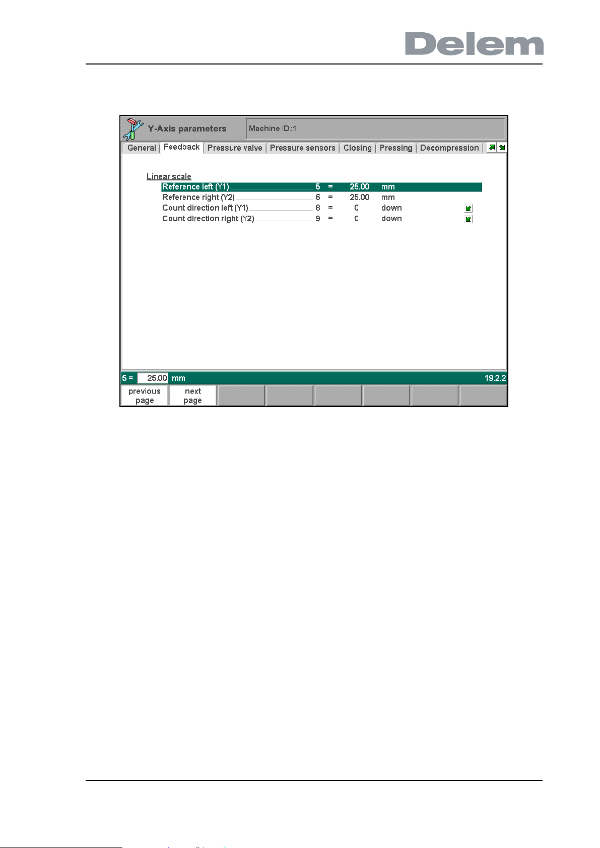
4.2.3. The Feedback page
4.c
V0908, 4.15

Parameter: 5
Reference left (Y1)
Range : 0.00-9999.99
Default : 25.00
Units : mm
Function
Y-axis left side linear scale reference position and parallelism adjustment.
Description
This value is displayed on the screen when the reference on the linear scale is passed. When
the reference marker on the linear scale is passed, a reference impulse is given to the
electronics. (To see left and right side separately switch service row on).
Note
This value must be greater than the mechanical travel distance on the scale from reference
point position to the scale end. This travel distance must also be greater than the mechanical
travel of the cylinder from reference point position to the upper dead point mechanical in the
cylinder.
Make sure that when the cylinder is on the mechanical upper dead stop the Y-axis value readout is between 5 and 10 mm.
V0908, 4.16

Parameter: 6
Reference right (Y2)
Range : 0.00-9999.99
Default : 25.00
Units : mm
Function
Y-axis right side linear scale reference position and parallelism adjustment.
Description
See description ‘Reference left’.
V0908, 4.17

Parameter: 8
Count direction left (Y1)
Range : 0-1
Default : 0
Units : -
Function
To change the counting direction of the linear scale encoder pulses of Y1.
Description
Generally the position counting of Y1 should be upcounting when the beam is moving down.
With this parameter the counting direction can be inversed to have it correct.
Press the key to select the required setting.
V0908, 4.18

Parameter: 9
Count direction right (Y2)
Range : 0-1
Default : 0
Units : -
Function
To change the counting direction of the linear scale encoder pulses of Y2.
Description
Generally the position counting of Y2 should be upcounting when the beam is moving down.
With this parameter the counting direction can be inversed to have it correct.
Press the key to select the required setting.
V0908, 4.19
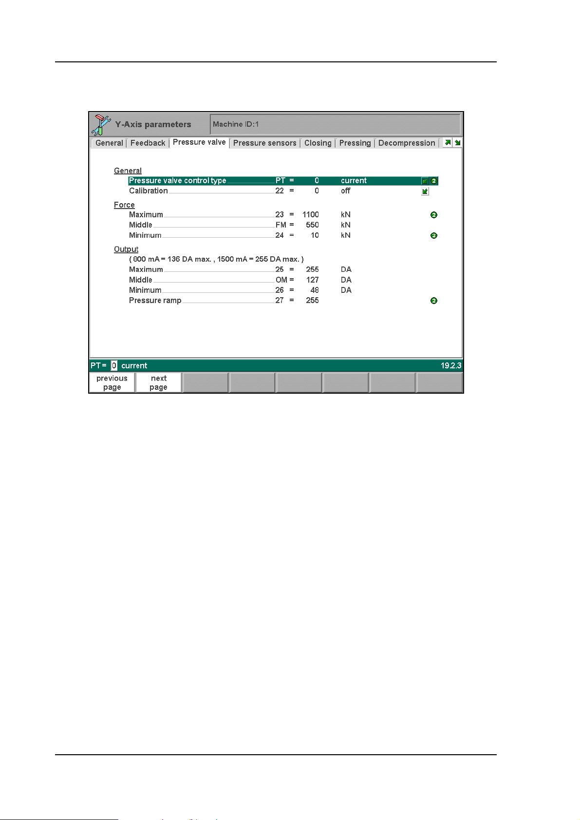
4.2.4. The Pressure valve page
4.d
V0908, 4.20

Parameter: PT
Pressure valve control type
Range : 0 - 1
Default : 0
Units : -
Function
To program the type of control that is required for the pressure valve:
0 = current
1 = voltage
V0908, 4.21

Parameter: 22
Calibration
Range : 0-1
Default : 0
Units : -
Function
Pressure valve calibration.
Description
Program ‘1' if you want to calibrate proportional pressure valve control. Press the key to
select the required setting. The units at the force parameter in manual mode will be in points
from 0 to 255 max. instead of tons. (0 = 0 mA, 255 = 1500 mA)
Calibration procedure:
1. Set parameter to ‘1';
2. Leave the machine parameter menu;
3. Go to the manual mode;
4. Program e.g. 200 points at the tonnage parameter;
5. Select bottoming;
6. Mount pressure gauge on hydraulic block (pump pressure);
7. Programm Dwell time = 5 s;
8. Perform a working stroke with the press. The tools are now pressed together (punch in
die) (Note:
9. When tools are pressed together read pressure gauge. In case the pressure is not
sufficient for max. tonnage, reprogram DA-output (max. 255) at tonnage parameter. Repeat
until your max. tonnage is reached. Remember output value. The value must be programmed
at machine parameter ‘output- max’.
10. Program a small value at tonnage parameter, e.g. 30 points. Now find min.value at
which the beam begins to move in the pressing mode. Make note of this minimum value. This
value must be programmed at machine parameter ‘output-min’.
11. Select again the machine parameters menu.
12. Now you must program at machine parameters ‘Force max.’ and ‘Force min.’ the
maximum and minimum tonnage of your press which corresponds with the force units (0-255)
at machineparameters ‘output -max’ and ‘output- min’.
Only use punch and die which may work on max. pressure)
V0908, 4.22
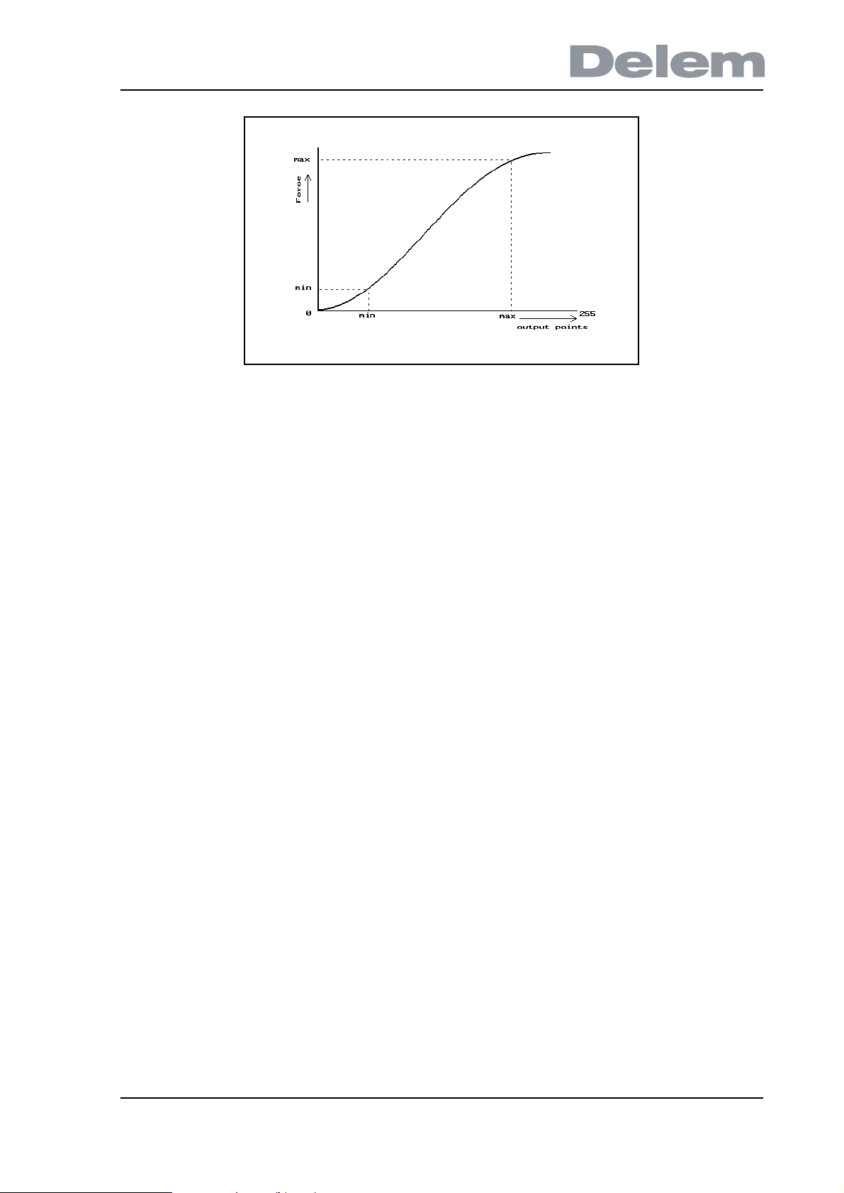
4.e
Note
The mechanical adjustment of the pressure valve has to be done before this calibration
procedure.
V0908, 4.23

Parameter: 23
Force maximum
Range : 0-6000
Default : 1100
Units : kN
Function
Maximal tonnage of press brake
Description
Maximal tonnage of the press brake is used to compute the pressure valve output deflection.
It is also used to check the programmed and computed values for the force. If the computed
force is greater than force max. the following error message will be displayed on the screen.
** computed force > force max. **
The message can also appear when the decompression distance is computed because the
control needs to compute the force before computing the decompression. When the start
button is pressed in manual mode or automatic mode, and the programmed force > force max
then the following error message will appear on the screen.
** programmed force > force max. **
The value programmed for force is limited at force max. See also calibration procedure
described with machine parameter calibration (parameter 22).
V0908, 4.24

Parameter: FM
Force Middle
Range : 0 - 6000
Default : ___
Units : kN
Pressure valve calibration enhancement
When the relation between the output deflection and the pressure is linear then you only have
to program force max. and force min. In case the relation between the output deflection and
the pressure is not linear you can program force middle.
The default value for this middle parameter is ‘___’, meaning that this parameter is not active.
V0908, 4.25

Parameter: 24
Force minimum
Range : 0-6000
Default : 100
Units : kN
Function
Minimal tonnage of press brake.
Description
Minimal tonnage of the press brake is used to compute the pressure valve output deflection. It
is also used to check the programmed force value. When the start button is pressed and the
programmed force is less than force min, the force is limited at force min. See also calibration
procedure described with machine parameter calibration.
V0908, 4.26

Parameter: 25
Output maximum
Range : 0-255
Default : 255
Units : DA-points
Function
Pressure valve deflection for max. force.
Description
Output deflection for proportional pressure valve in DA-points to give max. force. There are
two ranges of pressure valves:
- 800 mA. These valves can be programmed to max. 136 DA-points.
- 1500 mA. These valves can be programmed to max. 255 DA-points.
See also calibration procedure with machine parameter Calibration.
V0908, 4.27

Parameter: OM
Output middle
Range : 0 - 255
Default : ___
Units : DA-points
Pressure valve calibration enhancement.
When the relation betwee the output deflection and the pressure is linear then you only have
to program output max. and output min. In case the relation between the output deflection and
the pressure is not linear you can program output middle.
The default value for this middle parameter is ‘___’, meaning that this parameter is not active.
V0908, 4.28

Parameter: 26
Output minimum
Range : 0-255
Default : 48
Units : DA-points
Function
Pressure valve deflection for minimal force.
Description
Output deflection for proportional pressure valve in DA-points to give min.force.
There are two ranges of pressure valves:
- 800 mA. These valves can be programmed to max 136 DA-points.
- 1500 mA. These valves can be programmed to max 255 DA-points.
See also calibration procedure with machine parameter Calibration.
V0908, 4.29
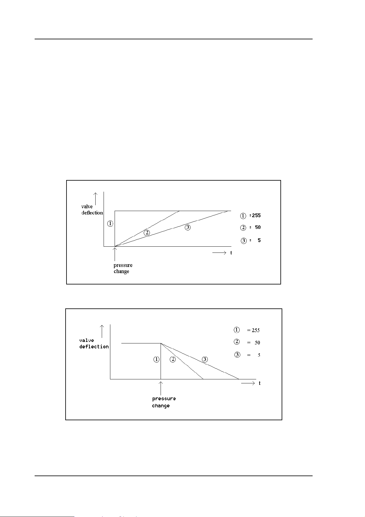
Parameter: 27
Pressure ramp
Range : 0 - 255
Default : 255
Units : DA-points / 5ms
Function
To program a ramp with which you control the pressure output.
Description
It is possible to program a ramp with which the pressure output will be activated. A lower value
will give a large ramp. This parameter is activated at every pressure change.
4.f
4.g
V0908, 4.30
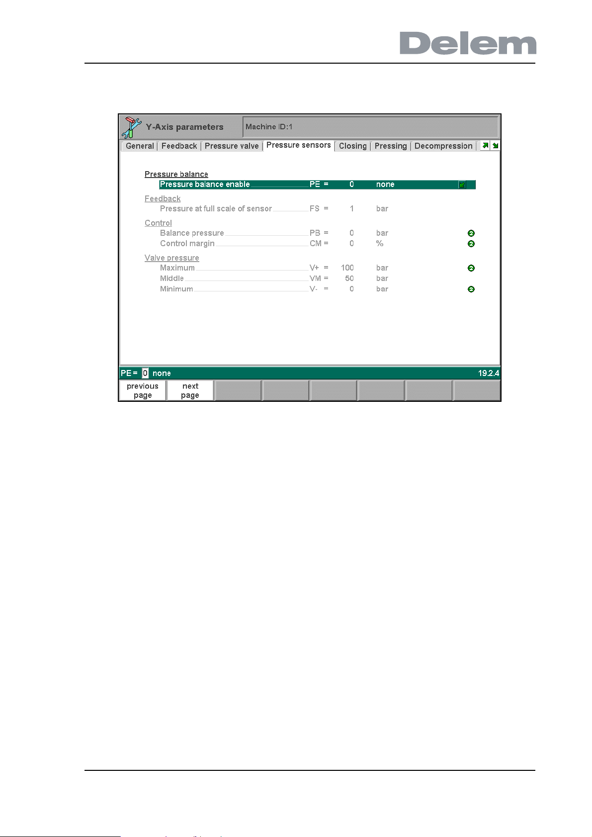
4.2.5. The Pressure sensors page
4.h
V0908, 4.31

Parameter: PE
Pressure balance enable
Range : 0 - 1
Default : 0
Units : -
Function
To switch the pressure balance function on the Y-axis module ON or OFF.
0 = OFF
1 = ON
Description
With the Pressure Balance feature, the pressure over the proportional valves is kept constant.
For this system three pressure sensors need to be mounted on the machine. One to measure
the system pressure and one for each Y-cylinder.
If this feature is enabled, the other parameters on this page need to be programmed. They are
descibed in this section.
V0908, 4.32

Parameter: FS
Pressure at full scale of sensor
Range : 1 - 999
Default : 1
Units : bar
Function
The maximum pressure value that can be measured. This value corresponds with a 10V
signal from the pressure sensor. This value refers to all three sensors.
V0908, 4.33

Parameter: PB
Balance pressure
Range : 1 - 999
Default : 1
Units : bar
Function
Balance pressure. This value will be added to the maximum of the measured pressure in the
upper side of he cylinders.
V0908, 4.34

Parameter: CM
Control margin
Range : 0 - 100
Default : 0
Units : %
Function
The allowed control range for the pressure control loop.
Description
The maximum deviation from the original setpoint is defined by this parameter. If this value is
too small, the desired pressure will not be reached.
The value that should be programmed also depends on how well the pressure valve has been
calibrated. If a value larger than 20% needs to be programmed, the pressure valve calibration
should be checked.
V0908, 4.35

Parameter: V+
Maximum valve pressure
Range : 1 - 999
Default : 1
Units : bar
Function
Maximum pressure value for the pressure valve.
Description
This pressure value should correspond with the maximum force and the maximum output, as
programmed in the “Pressure valve” page.
V0908, 4.36

Parameter: VM
Middle valve pressure
Range : 1 - 999
Default : 1
Units : bar
Function
Medium pressure value for the pressure valve.
Description
This pressure value should correspond with the middle force and the middle output, as
programmed in the “Pressure valve” page.
V0908, 4.37

Parameter: V-
Minimum valve pressure
Range : 1 - 999
Default : 1
Units : bar
Function
Minimum pressure value for the pressure valve.
Description
This pressure value should correspond with the minimum force and the minimum output, as
programmed in the “Pressure valve” page.
V0908, 4.38
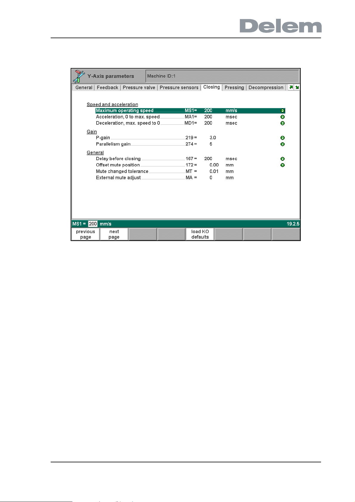
4.2.6. The Closing page
4.i
V0908, 4.39

Parameter: MS1
Maximum operating speed
Range : 10 - 500
Default : 200
Units : mm/s
Function
Maximum travel speed of the Y-axis during closing.
Description
This is the maximum speed at which the axis will travel. Normally this value should be
programmed to the maximum possible speed of the axis, when the control signal is at
maximum. This value may also be programmed to a lower value, to limit the maximum speed
the axis will travel.
Do not program this value too high, this will have a bad effect on the control system.
V0908, 4.40
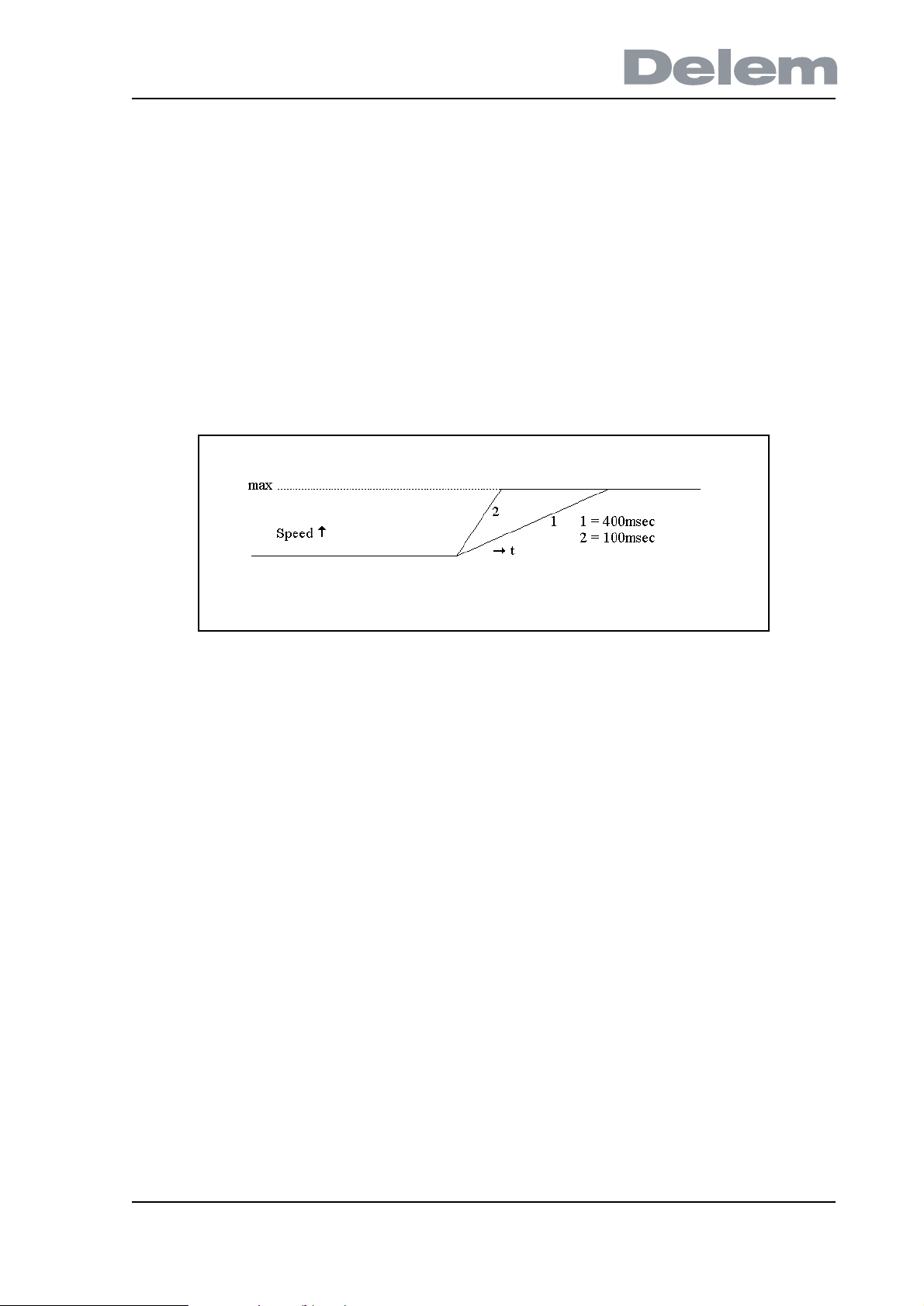
Parameter: MA1
Acceleration, 0 to max. speed
Range : 0 - 2000
Default : 200
Units : ms
Function
Acceleration time of the Y-axis.
Description
This is the nominal acceleration of the axis, used to control the axis from zero to maximum
speed in the closing phase. This parameter must be programmed as the time in which the axis
accelerates from zero to maximum speed.
4.j
V0908, 4.41

Parameter: MD1
Deceleration, max. speed to 0
Range : 0 - 2000
Default : 200
Units : ms
Function
Deceleration time of the axis.
Description
This is the nominal deceleration of the axis, used to control the axis from maximum to zero
speed when the axis comes into position. This parameter must be programmed as the time in
which the axis decelerates from maximum to zero speed.
4.k
V0908, 4.42

Parameter: 219
P-gain
Range : 0.1 - 99.9
Default : 2.5
Units : -
Function
Proportional gain factor for the Y-axis during closing.
Description
This gain factor defines the response to changes in the control signal. A high gain gives a
quick response, if the gain is too high it will cause oscillation.
V0908, 4.43

Parameter: 271 (level 3)
Feedforward friction value
Range : 0.0 - 999.9
Default : 0
Units : -
Function
Gain factor for the axis when approaching the programmed position.
Description
This parameter should be programmed to obtain a quick and smooth approach to mute point.
V0908, 4.44
 Loading...