

Page 1

(W)
INSTALLATION INSTRUCTIONS
GRILLE GUARD
07-12 SILVERADO 1500
Part # 501514 & 501515
Page 2
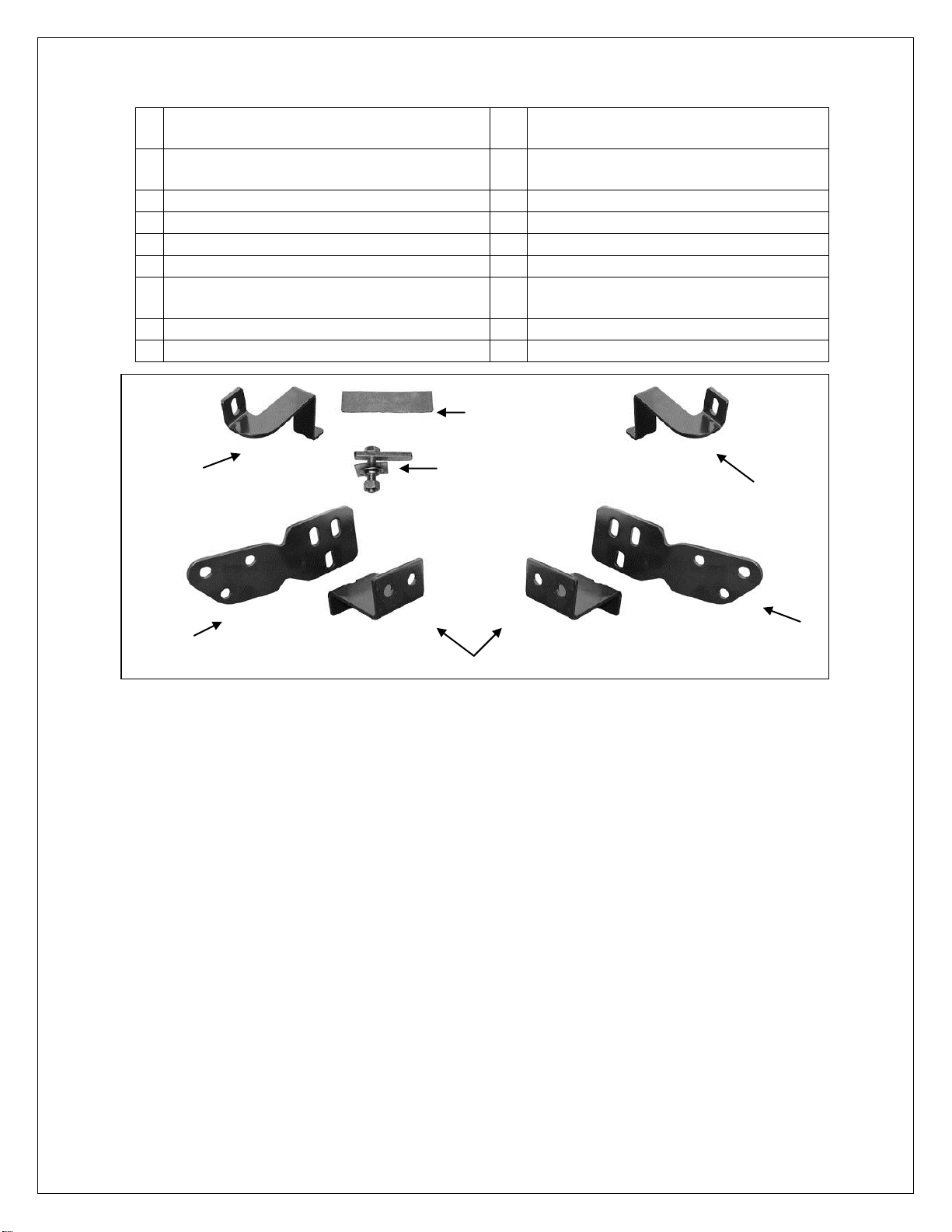
GRILLE GUARD
1
Grille Guard
10
12mm x 24mm OD x 2.5mm STD Flat
Washers
1
Driver/Left Top Bracket
12
12mm x 32mm OD x 3mm Large Flat
Washers
1
Passenger/Right Top Bracket
12
12mm Nylon Lock Nuts
2
Frame Mounting Brackets
2
10-1.50mm x 25mm Button Head Bolts
2
Lower Frame Support Brackets
4
10mm x 20mm x 2mm Flat Washers
2
12-1.75mm x 40mm Bolt Plates (#11)
2
10mm Nylon Lock Nuts
2
12mm Plastic Retainers
2
600mm x 50mm x 1.0mm Adhesive
Backed Foam Tape
2
12-1.75mm x 140mm Hex Bolts
1
6mm Allen Wrench
8
12-1.75mm x 30mm Hex Bolts
Frame
Mounting
Bracket
Frame
Mounting
Bracket
Driver/Left Top
Bracket
Passenger/Right Top
Support Bracket
(2) Lower Support Brackets
(2) 12mm x 40mm Bolt
Plates (pictured w/hardware)
Adhesive Backed
Foam Tape
07-12 SILVERADO 1500
PARTS LIST:
PROCEDURE:
1. REMOVE CONTENTS FROM BOX AND VERIFY ALL PARTS ARE PRESENT. READ INSTRUCTIONS
CAREFULLY. DO NOT ATTEMPT INSTALLATION ALONE; PERSONAL INJURY OR DAMAGE TO
THE VEHICLE MAY RESULT. CUTTING IS REQUIRED.
2. Start installation from under the front of the vehicle. Determine if the vehicle is equipped with tow hooks.
a. Vehicles equipped with tow hooks and/or openings in bumper cover: Remove the factory tow
hooks, if equipped, (Figure 1). NOTE: This Grille Guard is not compatible with factory tow hooks.
b. Vehicles without tow hooks and no openings in bumper cover: Remove the plastic lower
bumper cover. Place bumper cover on a clean, stable work surface, (Figure 2).
3. Locate the (2) holes, side by side, in the forward end of each frame channel. Insert (1) Bolt Plate into the
open end of the frame channel and out the rearmost hole in the side of the frame, (Figure 3). Thread (1)
12mm Plastic Retainer onto the threaded end of the Bolt Plate to hold the Bolt Plate in position during
Bracket installation, (Figure 4).
a. On the passenger side, the (2) holes are on the outer wall of the frame rail, (Figures 3, 4 & 7A).
b. On the driver side, the (2) holes will be on the inner wall of the frame, (Figure 8B).
4. Select (1) Mounting Bracket and (1) Support Bracket. NOTE, on vehicles with openings in bumper
cover, it may be necessary to enlarge the (2) openings in the bumper cover slightly to clear the Mounting
Brackets, (Figure 6). Trim cover as required to install Brackets.
a. Passenger/Right side Mounting Bracket installation: Secure the Mounting Bracket to the Bolt
Plate with (1) 12mm x 24mm STD Flat Washer and (1) 12mm Nylon Lock Nut. Select (1) Lower
Support Bracket. Line up the forward hole in the Support Bracket with the hole in the inner wall of
the frame channel. Insert (1) 12mm x 140mm Long Hex Bolt and (1) 12mm x 24mm STD Flat
Washer through the Support Bracket, both sides of the frame channel and out the remaining hole
Page 1 of 5 12/18/12 Rev1(DP)
Page 3

GRILLE GUARD
07-12 SILVERADO 1500
in the Mounting Bracket, (Figures 5, 7A & 7B). Secure with the included (1) 12mm x 24mm STD
Flat Washer and (1) 12mm Nylon Lock Nut.
Line up the hole in the bottom of the Support Bracket with the lower hole in the Mounting Bracket.
Bolt the (2) Brackets together with the included (1) 12mm x 30mm Hex Bolt, (2) 12mm x 24mm
STD Flat Washers and (1) 12mm Nylon Lock Nut, (Figures 7A & 7B). Do not fully tighten
hardware.
b. Driver/Left side Mounting Bracket installation: Select (1) Lower Support Bracket. Line up the
rear hole in the Support Bracket with the previously installed Bolt Plate. Secure the Support
Bracket to the Bolt Plate with (1) 12mm x 24mm STD Flat Washer and (1) 12mm Nylon Lock Nut,
(Figures 8A & 8B). Do not tighten at this time.
Select (1) Mounting Bracket. Insert (1) 12mm x 140mm Long Hex Bolt and (1) 12mm x 24mm STD
Flat Washer through the forward hole in the Support Bracket, both sides of the frame channel and
out the forward hole in the Mounting Bracket, (Figures 8A & 8B). Secure the Mounting Bracket
with the included (1) 12mm x 24mm STD Flat Washer and (1) 12mm Nylon Lock Nut.
Bolt the bottom of the Support Bracket to the Mounting Bracket as previously described in Step 4a,
(Figures 8A & 8B). Do not fully tighten hardware.
5. Next, open the hood and remove the plastic cover between the top of the grille and the radiator. NOTE:
Use a small flat head screw driver to pop up the center of the plastic clips. Remove the two outer bolts
from the grille shell. Use a pair of “needle nose” pliers to carefully squeeze the back of the clips to release
as you gently pull the grill forward, (Figure 9). IMPORTANT: Do not damage the clips holding the grille in
place. Once all of the clips have been released, carefully remove the grille by gently pulling it forward from
the vehicle
6. Remove the long factory top bumper bracket bolt behind the bumper on the top of the frame. Select the
driver side Top Bracket. Apply a layer of Adhesive Backed Foam Tape to the inside of the Bracket to
protect the finish on the bumper, (Figure 10). IMPORTANT: To prevent the Top Brackets from damaging
the finish on the vehicle during installation, cover the top of the bumper with removable tape, (masking
tape). Secure the Top Bracket to the bumper bracket with the factory hex bolt, (Figure 11). Leave the
hardware loose at this time. Repeat this Step to install the passenger side Top Bracket.
7. With assistance, hold the Grille Guard up in position on the outside of the Mounting Brackets. Bolt the
Grille Guard to the Brackets with (6) 12mm x 30mm Hex Bolts, (12) 12mm x 32mm Large Flat Washers
and (6) 12mm Nylon Lock Nuts, (Figures 7A & 8B). Snug but do not tighten hardware at this time.
8. Line up the driver side Top Bracket with the hole in the upright on the Grille Guard. Bolt the Top Bracket to
the upright with (1) 10mm Button Head Bolt, (2) 10mm Flat Washers and (1) 10mm Nylon Lock Nut,
(Figure 12). Do not tighten hardware at this time. Repeat for passenger side Top Bracket installation.
9. Level and adjust the Grille Guard. Make sure that the Top Brackets do not come in contact with the top of
the bumper cover.
a. Vehicles equipped with tow hooks and/or opening in bumper cover: Proceed to tighten all
hardware.
b. Vehicles without tow hooks and no openings in bumper cover: Tighten the lower Mounting
Bracket hardware only. Temporarily remove the Grille Guard. Hold the lower bumper cover up in
position and mark the location of the Mounting Brackets onto the back of the cover. Cut (2) vertical
slots through the bumper cover to clear the Brackets. Cut as little as possible from the bumper
cover. Reinstall the bumper cover over the Brackets. Reinstall the Grille Guard as described in
Steps 7 – 8. Level and adjust the Grille Guard and tighten all hardware at this time.
10. Once all mounting hardware is tight, line up the clips on the grille with the mounting tabs, (Step 5), and
gently push the grille back into place. Reinstall the top plastic cover.
11. Do periodic inspections to the installation to make sure that all hardware is secure and tight.
To protect your investment, wax this product after installing. Regular waxing is recommended to add a protective layer over
the finish. Do not use any type of polish or wax that may contain abrasives that could damage the finish.
For stainless steel: Aluminum polish may be used to polish small scratches and scuffs on the finish. Mild soap may be used
also to clean the Grille Guard.
For gloss black finishes: Mild soap may be used to clean the Grille Guard.
Page 2 of 5 12/18/12 Rev1(DP)
Page 4

GRILLE GUARD
(Fig 1) Opening for tow hook pictured
(Fig 2) No opening in bumper cover
(Fig 3) Passenger side frame channel pictured
(Fig 5) Passenger side Mounting
Bracket installation pictured
(1) 12mm Bolt Plate
(1) 12mm Plastic Retailer
(on outside)
(1) 12mm x 140mm Hex Bolt
(1) 12mm Flat Washer
(Fig 4) Passenger side Bolt Plate with
Plastic Retainer pictured from below
(1) 12mm Bolt Plate
(1) 12mm Plastic Retailer
Front
Front
Fig 6
Front
07-12 SILVERADO 1500
Page 3 of 5 12/18/12 Rev1(DP)
Page 5

GRILLE GUARD
Fig 8B
Fig 8A
Fig 7B
Fig 7A
(1) 12mm x 140mm Hex Bolt
(1) 12mm Flat Washer
(1) 12mm x 140mm Hex Bolt
(2) 12mm Flat Washer
(1) 12mm Nylon Lock Nut
(1) 12mm x 30mm Hex Bolt
(2) 12mm Flat Washers
(1) 12mm Nylon Lock Nut
Front
Front
Front
Front
(1) 12mm Bolt Plate
(1) 12mm Plastic Retailer
(1) 12mm Flat Washer
(1) 12mm Nylon Lock Nut
(1) 12mm x 140mm Hex Bolt
(2) 12mm Flat Washer
(1) 12mm Nylon Lock Nut
(1) 12mm x 30mm Hex Bolt
(2) 12mm STD Flat Washers
(1) 12mm Nylon Lock Nut
(1) 12mm x 30mm Hex Bolt
(2) 12mm Large Flat Washers
(1) 12mm Nylon Lock Nut
(1) 12mm Bolt Plate
(1) 12mm Plastic Retailer
(1) 12mm Flat Washer
(1) 12mm Nylon Lock Nut
07-12 SILVERADO 1500
Passenger Side Mounting Bracket Installation Pictured
Driver Side Mounting Bracket Installation Pictured
Page 4 of 5 12/18/12 Rev1(DP)
Page 6

GRILLE GUARD
Fig 9
(Fig 11) Driver side Top Bracket installation pictured
without foam for instruction purposes only
Front
Front
Front
Factory bumper
bracket bolt
(1) 10mm Button Head Bolt
(2) 10mm Flat Washers
(1) 10mm Nylon Lock Nut
Use a pair of needle nose pliers
to carefully pinch the top and
bottom tab on the clip to release
and remove the grille
Complete Installation
(Fig 10) Apply adhesive backed Foam
Tape to inner and outer surface of Top
Brackets to protect factory bumper
(Fig 12) Driver side Top Bracket installation
pictured. Apply foam tape to Bracket. Apply
a layer of masking tape to the top of the
bumper for protection during installation
07-12 SILVERADO 1500
Driver Side Mounting Bracket Installation Pictured
Page 5 of 5 12/18/12 Rev1(DP)
 Loading...