

Page 1
Before returning this product
DZ 91781
to the store of purchase
Contact Dee Zee if you experience the following problems:
•MissingParts
•InstallationProblems/Questions
•WarrantyQuestions
1.800.779.2102
Hoursofoperation:8am-5pmCST,Mon-Friday
Reviewcompletewarrantypolicyandregisteryourproductat:
www.deezee.com
Page 2
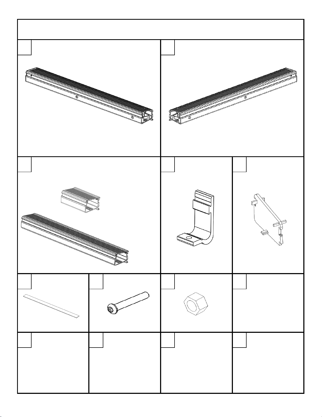
IR-HOUSING-ASSEML
X2
IR-HOUSING-ASSEMR
X2
6 FT.
INVIS-A-RACK INSTALLATION INSTRUCTION
DZ 951550, DZ 951600, DZ 951800
A B
8 FT.
VARIES
X2
DZE-539-150CP
X8
ECIR4
X4
FGT 32
16 FT.
PN 220
X8
PN 90
X8
DRIVER FRONT / PASSENGER REAR PASSENGER FRONT / DRIVER REAR
BUNGEE BOX
THERE IS NO BUNGEE BOX IN THE 5 FT. APPLICATION
FOAM GASKET 3/8" BOLT 3/8" NUT
F G H
MOUNTING HOOK SECTION CAP
EDC
Invis-A-Rack 1 of 15 3/6/2013
Page 3
WRENCH
UTILITY KNIFE OR SCISSORS
9/16"
7/32" ALLEN WRENCH OR SOCKET
RATCHET
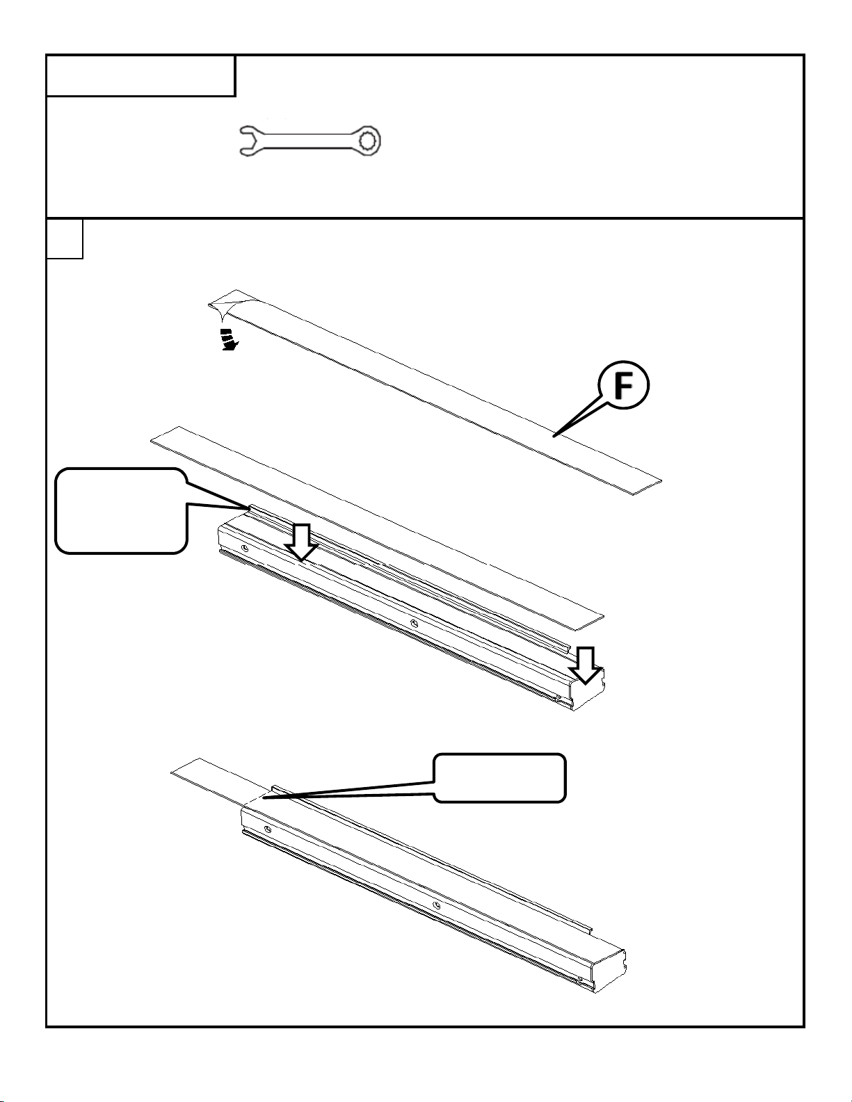
Peel a portion of the paper back from the adhesive on the foam gasket [F].
Apply the sticky side of the gasket to the bottom of the rack assemblies and bungee boxes (if applicable).
Use the lip on the bottom side as a guide to apply the gasket straight with the part.
TOOLS REQUIRED
After applying the gasket, use a utility knife to trim the gasket with the end of the part.
1
ALIGN GASKET
WITH THIS
EDGE
TRIM AT EDGE
Invis-A-Rack 2 of 15 3/6/2013
Page 4

If your application includes bungee boxes, they will need to be assembled.
With the lid held almost perpendicular
to the base, align the hook on the back
of the lid with the channel on the base.
Slide the lid onto the base.
2
When the edges are flush, close the lid.
BASE
LID
Invis-A-Rack 3 of 15 3/6/2013
Page 5
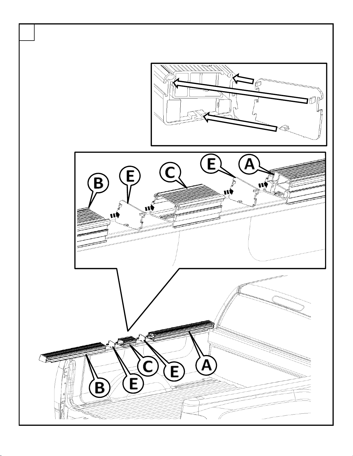
Set the first assembly [A] on the bed of the truck on the driver's side near the cab.
This step is shown with the small bungee box for the 6' bed. If you are installing on a 5.5' bed, there
will not be a bungee box, and you will only use one of the section cap [E] per side.
If you are installing on an 8' bed, the bungee box will be longer than what is shown
below, but will install in the same way.
Assemble the sections as shown below.
The tabs in the section cap [E] fit into
the extrusion as shown in this figure.
When installed to outside profile of the
section cap will match the extrusion
profile.
3
Invis-A-Rack 4 of 15 3/6/2013
Page 6

Thread one of the 3/8" nuts [H] onto the 3/8" bolt [G], then thread the bolt part way
into the hole on the hold down clamp [D]. There will be 4 of these used per side.
Slide the 4 hold down clamps into the bottom channel on the back side.
4
Invis-A-Rack 5 of 15 3/6/2013
Page 7
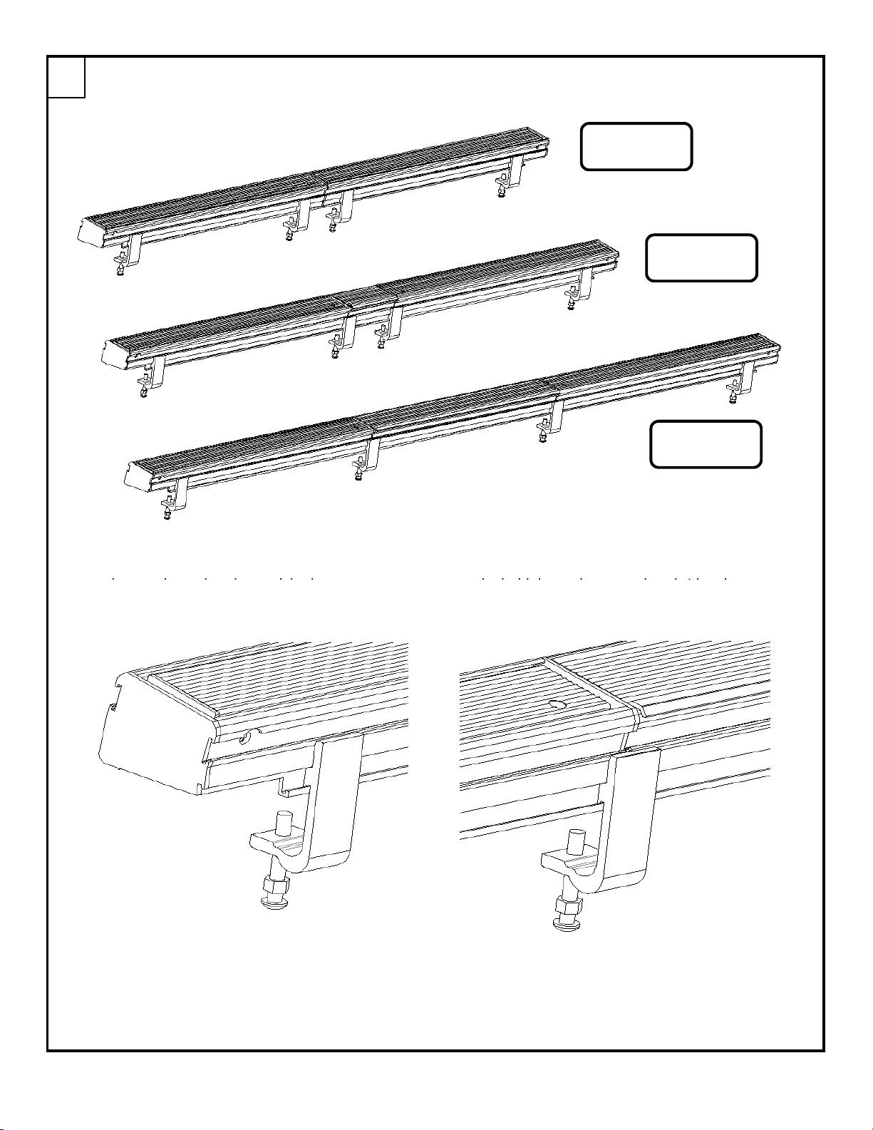
Use the images below to locate the hold down clamps for each truck bed length.
The end hold down clamps should be
For applications with the bungee box,
5
as close to the end as the truck bed
the hold down clamp needs to bridge the
allows, but still completely in the
joint between the rack section and the
channel of the extrusion.
bungee box equally.
Note: Some trucks will have a center stake hole that will not allow the hold down clamp to bridge the
joint of the main housing and bungee box. In this case, it is important to make sure that the two
hold down clamps are installed on the front main housing and two hold down clamps are installed
on the rear main housing (One as far forward as possible and one as far back as possible).
5.5' BED
6' BED
8' BED
Invis-A-Rack 6 of 15 3/6/2013
Page 8
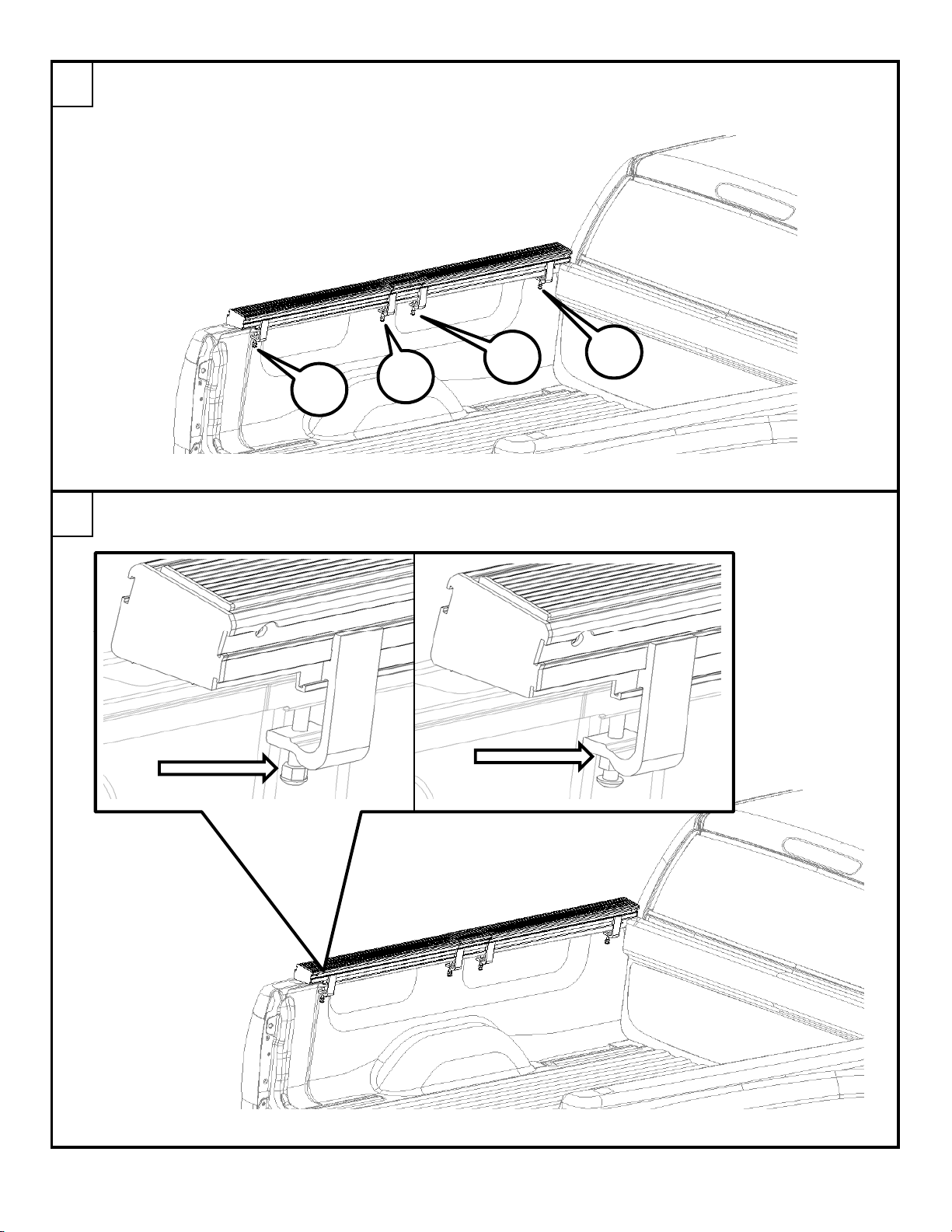
Tighten the bolts using a 7/32" allen wrench/socket. Start with the bolt closest to the cab and work
your way to the bolt at other end of the bed. Repeat the process of tightening the bolts to insure that
all are completely tighten.
Once the 3/8" bolts have been tightened, using a 9/16" open end wrench, tighten the nut against the
bottom of the hold down clamp.
6
1
2
3
4
7
Invis-A-Rack 7 of 15 3/6/2013
Page 9
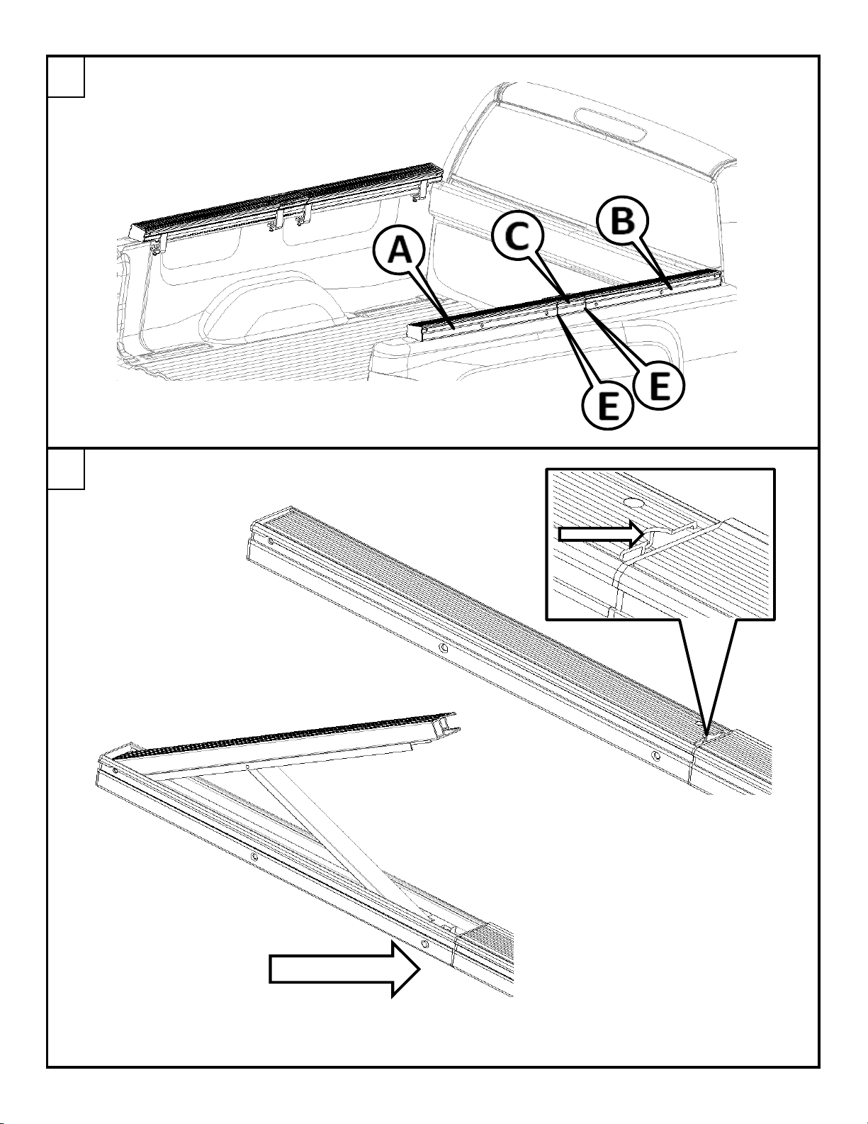
Repeat these installation steps for the other side of the bed.
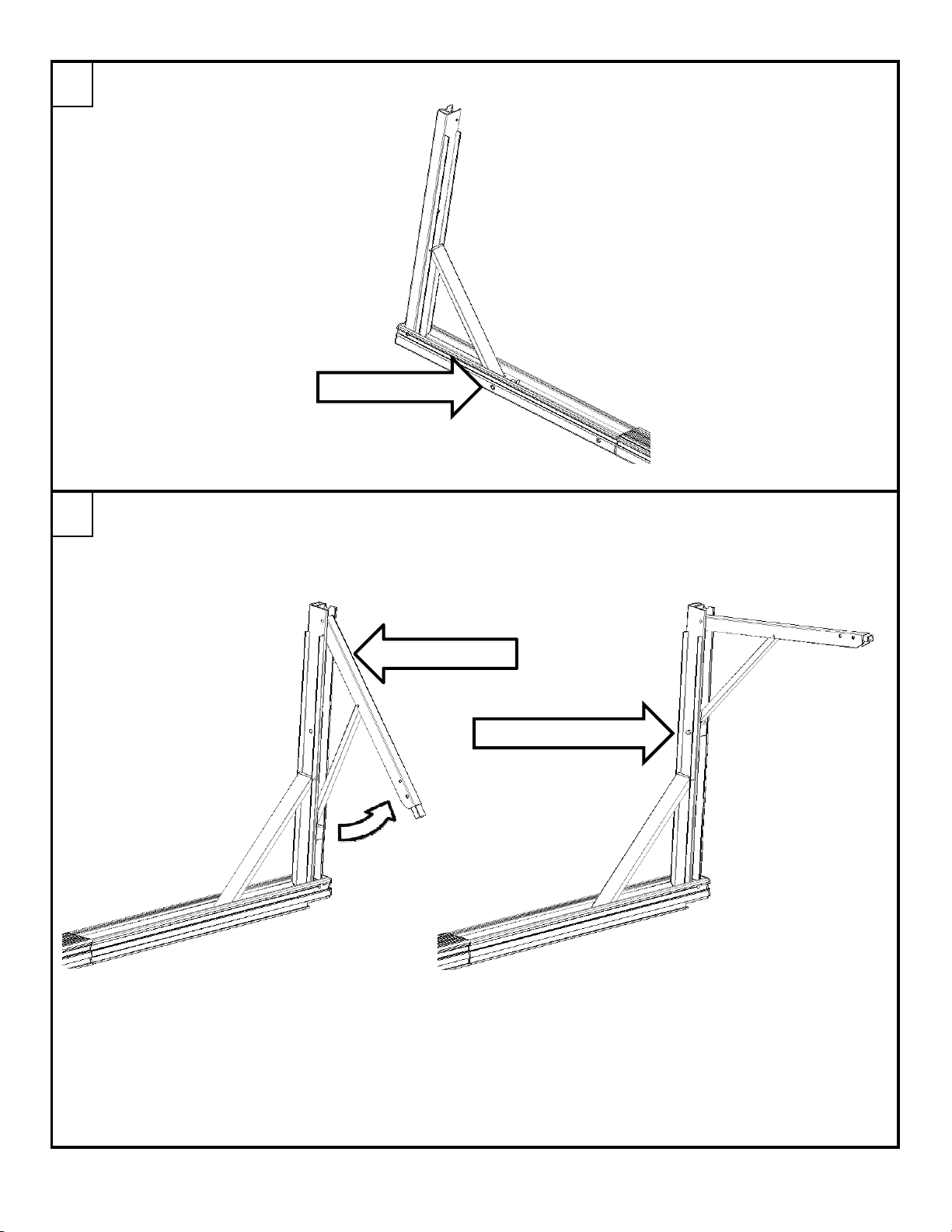
To use the Invis-a-rack, pull up on the top section
using the cut out provided.
8
There is a safety stop on the side
to prevent the rack from slamming
down when closing it. Depress the
push button to allow the top section
to be opened all the way.
9
SAFETY STOP
Invis-A-Rack 8 of 15 3/6/2013
Page 10
Extend the top section until the spring button engages the second hole on the side.
On the inside of the top section, pull up on the material arm.
Extend the material arm until the push button engages.
10
Repeat these steps for the other side.
11
2nd HOLE
MATERIAL ARM
PUSH BUTTON HOLE
Invis-A-Rack 9 of 15 3/6/2013
Page 11
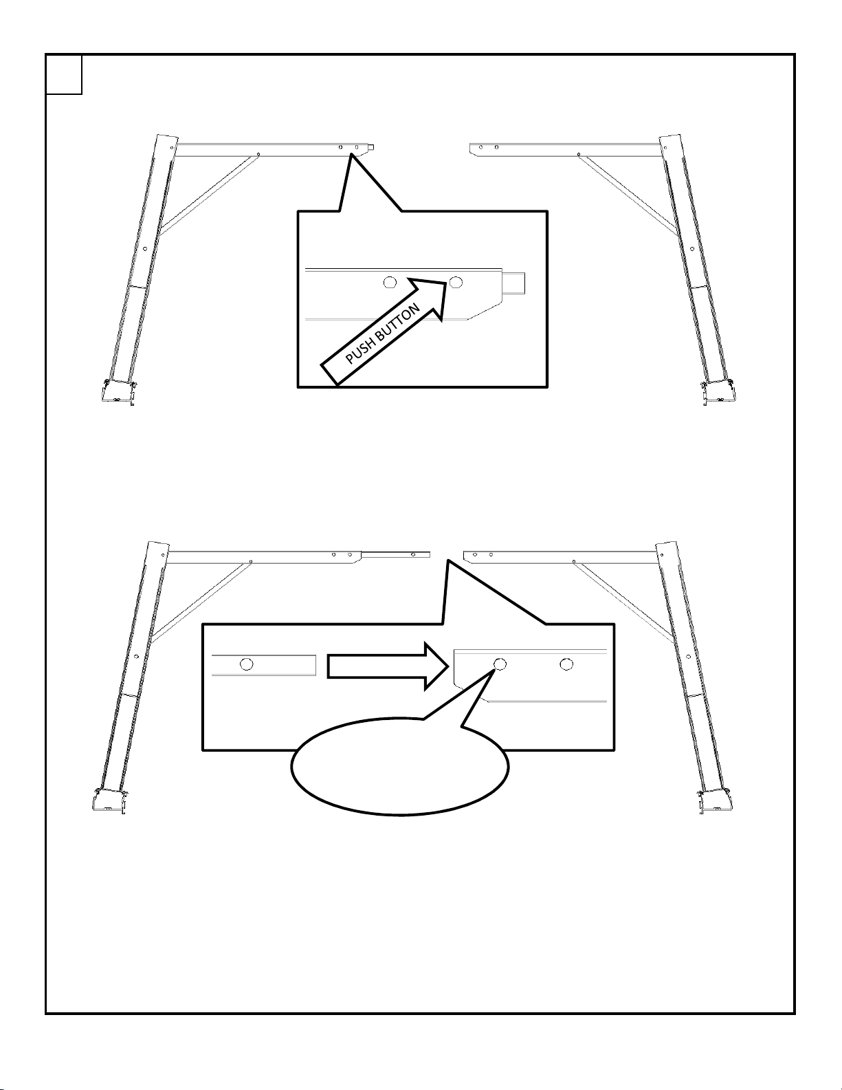
Once both sides have been extended, press the push button in the cross bar and pull it out.
Insert the cross bar into the other side of the rack and engage the push button in the first hole.
12
INSERT
BAR
ENGAGE PUSH
BUTTON HERE
Invis-A-Rack 10 of 15 3/6/2013
Page 12
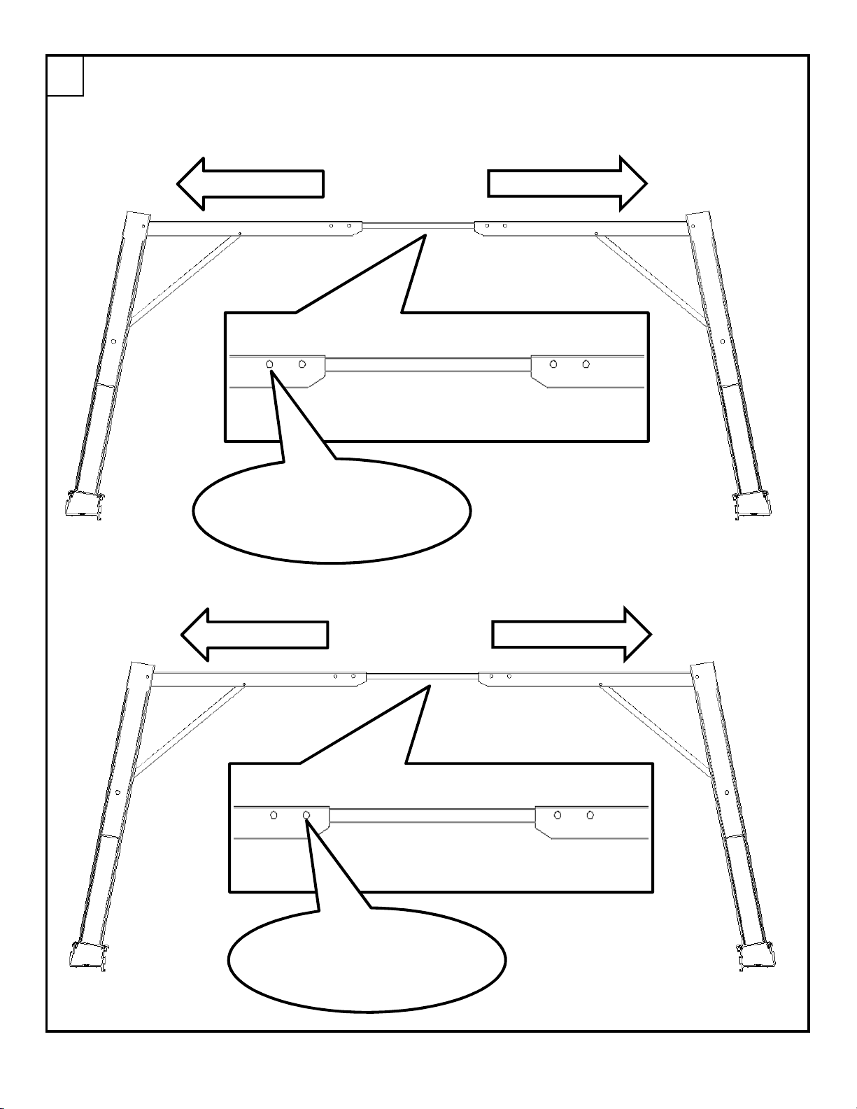
After engaging the push button, push the two halves of the rack apart, until the other push
button engages. Do NOT use the rack with out both push buttons engaged.
13
When installed on the Ford superduty, the second push button will engage the 2nd hole.
PUSH THIS WAY
PUSH BUTTON WILL
ENGAGE HERE ON THE
PUSH THIS WAY
BACKSIDE
PUSH THIS WAY
PUSH BUTTON WILL
ENGAGE HERE ON THE
PUSH THIS WAY
BACKSIDE
Invis-A-Rack 11 of 15 3/6/2013
Page 13
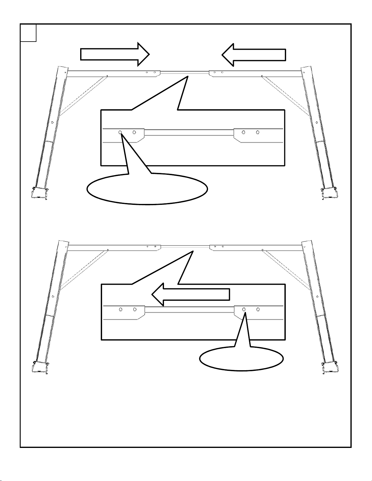
To stow the Invis-a-rack, depress the push button that was engaged in the previous step and pull
the two haves of the rack towards each other.
Disengage the other push button on the cross bar and slide it out.
14
PULL THIS WAY
PUSH BUTTON ON THE
PULL THIS WAY
BACKSIDE
SLIDE BAR THIS WAY
PUSH BUTTON
Invis-A-Rack 12 of 15 3/6/2013
Page 14
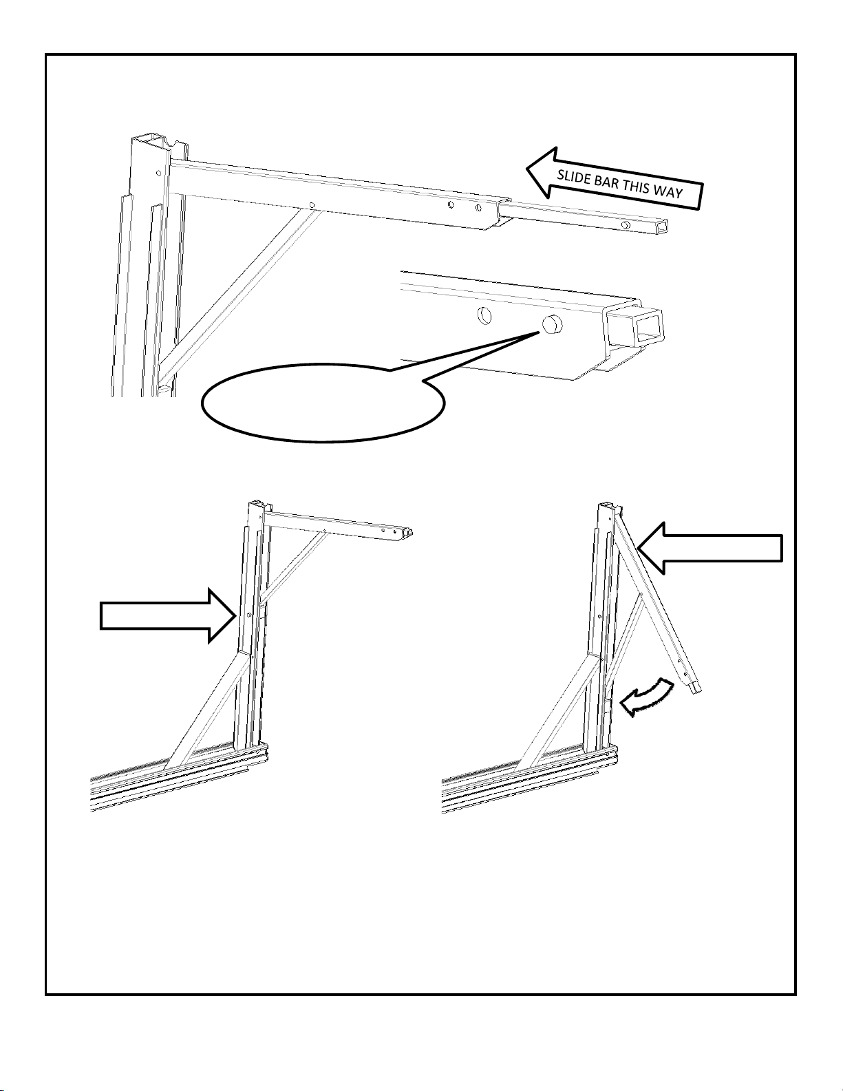
Slide the cross bar back until the push button engages in the first hole.
Depress the push button and bring the material arm down.
PUSH BUTTON
PUSH BUTTON WILL
ENGAGE HERE
MATERIAL ARM
Invis-A-Rack 13 of 15 3/6/2013
Page 15
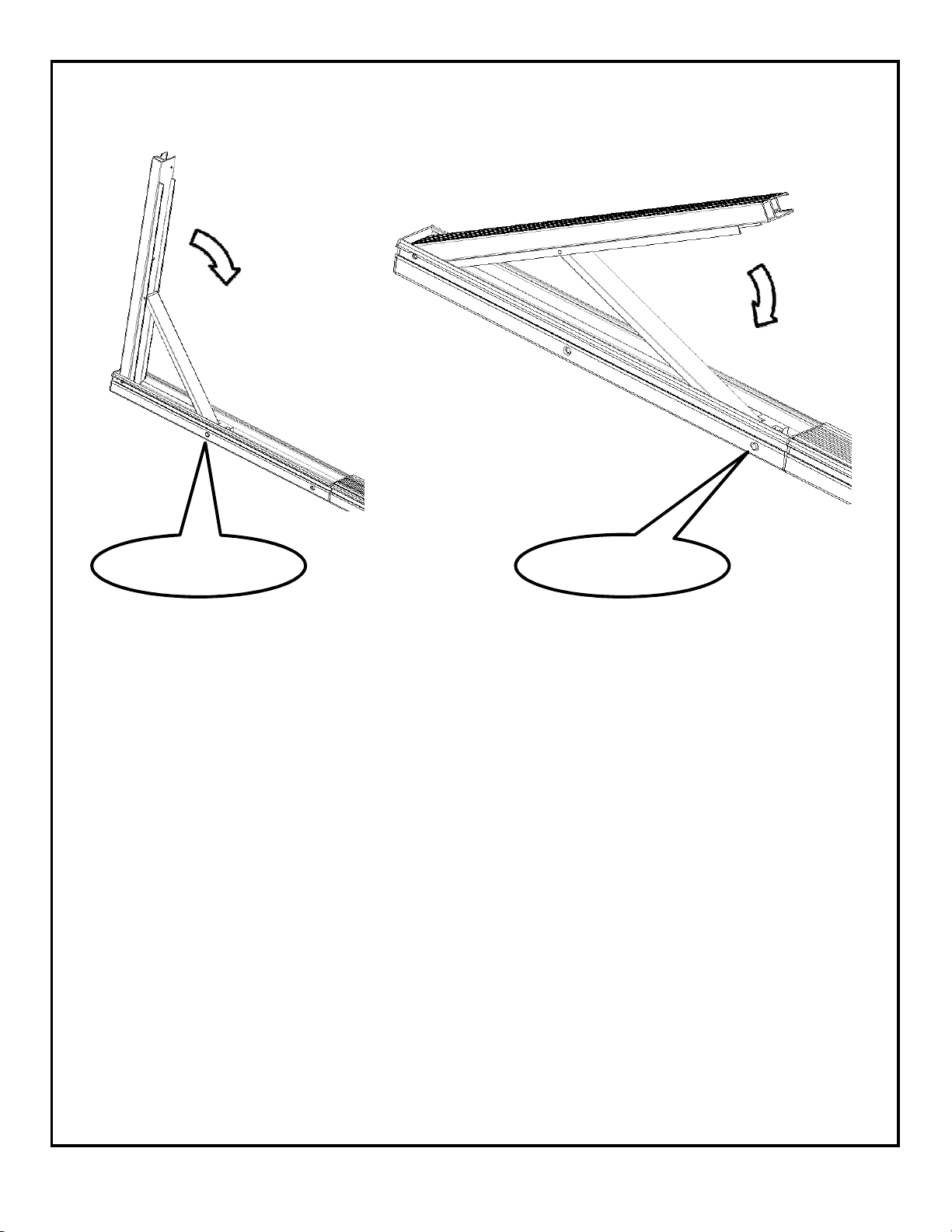
Depress the push button to lower the remaining part of the rack.
Then depress the push button in safety stop to complete the stowing of the rack.
PUSH BUTTON PUSH BUTTON
Repeat these step for the remaining portions of the rack.
Invis-A-Rack 14 of 15 3/6/2013
Page 16
To see a video showing the rack being put up, please use the QR code below.
*
Review & assure understanding of all load, handling, operating limitations and
safety messages contained in your Vehicle Owners Manual. Maximum Invis-a-rack
WARNING
load is 500 lbs. (evenly distributed & secured).
*
Ensure all fasteners & supports used to erect Invis-a-rack front & rear frames are fully
engaged & secured. Inspect frequently and do not use Invis-a-rack if damaged or
subjected to unintended overload.
*
Required set-up and stowage if Invis-a-rack involves pinch points where braces and
cross pieces attach. Keep fingers clear and do not attempt to set-up or stow with
load on Invis-a-rack.
*
CAUTION! Hold down clamps must remain secured to support Invis-a-rack and load.
Check often (particularly if rough road) and retighten as necessary. To avoid loss
or damage to load & risks to others: NEVER USE HOLD DOWN CLAMPS AS
ATTACHMENT FOR STRAPS OR OTHER MEANS OF SECURING LOAD. ALWAYS
SECURE LOADS DOWN TO FACTORY (OEM) TIE DOWNS.
Invis-A-Rack 15 of 15 3/6/2013
 Loading...