

DeDietrich MPX 28/33 BIC, MPX 24 COMPACT, MPX 20/24 MI COMPACT, MPX 24/28 MI COMPACT, MPX 28/33 MI COMPACT Instruction Manual
Page 1
A
MPX 28/33 BIC
en CONDENSING GAS WALL-HUNG BOILERS
Instructions manual for users and tters
pl NAŚCIENNY GAZOWY KOCIOŁ KONDENSACYJNY
Instrukcja obsługi dla użytkowników i instalatorów
cs PLYNOVÝ ZÁVĚSNÝ KONDENZAČNÍ KOTEL
Návod na použití určený pro uživatele a instalatéra
sk PLYNOVÝ ZÁVESNÝ KONDENZAČNÝ KOTOL
Návod na použitie určený pre používateľa a inštalatéra
fr CHAUDIERES MURALES A GAZ A CONDENSATION
Notice d’emploi et d’installation destinée à l’usager et à l’installateur
ro CENTRALĂ TERMICĂ MURALĂ CU CONDENSARE, PE GAZ
Manual de instrucţiuni destinat utilizatorului şi instalatorului
el ΕΠΙΤΟΙΧΙΟΣ ΛΕΒΗΤΑΣ ΑΕΡΙΟΥ ΣΥΜΠΥΚΝΩΣΗΣ
Εγχειρίδιο χρήσης για τον χρήστη και τον εγκαταστάτη
ru НАСТЕННЫЙ ГАЗОВЫЙ КОНДЕНСАЦИОННЫЙ КОТЕЛ
Паспорт изделия. Руководство по установке и эксплуатации
Page 2
Dear Customer,
Our company is condent our new product will meet all your requirements. Buying one of our products guarantees all your
expectations: good performance combined with simple and rational use.
Please do not put this booklet away without reading it rst: it contains useful information for the correct and efcient use of your
product.
Our company declares that these products are marked in compliance with the essential requirements of the
following Directives:
- Gas Directive 2009/142/EC
- Efciency Directive 92/42/EEC
- Electromagnetic Compatibility Directive 2014/30/EU
- Low Voltage Directive 2014/35/EU
- Ecodesign directive 2009/125/EC
- Energy labelling directive 2010/30/EU
(for boilers with Power<70kW)
- Ecodesign regulation (EU) No 813/2013
- Energy labelling regulation (EU) No 811/2013 (for boilers with Power<70kW)
Our company, constantly striving to improve the products, reserves the right to modify the details given in this documentation
at any time and without notice. These Instructions are only meant to provide consumers with use information and under no
circumstance should they be construed as a contract with a third party.
The appliance can be used by children aged 8 or over and by people with reduced
physical, sensory or mental faculties, or who do not have the required experience
or knowledge, provided they are supervised or have received instructions on using
the appliance safely and understanding its intrinsic hazards. Children must not play
with the appliance. The cleaning and maintenance operations reserved to the user
must not be performed by unsupervised children.
CONTENT
DESCRIPTION OF SYMBOLS .....................................................................................................................................................................3
SAFETY WARNINGS ....................................................................................................................................................................................3
GENERAL PRECAUTIONS .........................................................................................................................................................................4
ENERGY-SAVING TIPS ................................................................................................................................................................................4
1. COMMISSIONING THE BOILER ..................................................................................................................................................................5
1.1 ADJUSTING THE CH AND DHW FLOW TEMPERATURE ..........................................................................................................................5
1.2 OPERATING MODES ...................................................................................................................................................................................5
2. PROLONGED SHUTDOWN. ANTI-FREEZE PROTECTION .......................................................................................................................6
3. GAS CONVERSION .....................................................................................................................................................................................6
4. FAULTS .........................................................................................................................................................................................................6
5. BOILER INFORMATION MENU ...................................................................................................................................................................7
6. SWITCHING OFF THE BOILER ...................................................................................................................................................................7
7. FILLING THE SYSTEM .................................................................................................................................................................................7
8. ROUTINE MAINTENANCE INSTRUCTIONS ...............................................................................................................................................7
INSTRUCTIONS PRIOR TO INSTALLATION ...............................................................................................................................................8
9. INSTALLING THE BOILER ...........................................................................................................................................................................8
9.1 CONTENTS OF PACK ..................................................................................................................................................................................8
9.2 BOILER DIMENSIONS AND GAS WATER CONNECTIONS .......................................................................................................................8
10. INSTALLING THE FLUE ...............................................................................................................................................................................9
10.1 CONCENTRIC DUCTS .................................................................................................................................................................................9
10.2 SEPARATE DUCTS ......................................................................................................................................................................................10
User & Installer (en)
11. ELECTRICAL CONNECTIONS .....................................................................................................................................................................11
11.1 CONNECTING THE ROOM THERMOSTAT .................................................................................................................................................11
11.2 ACCESSORIES NOT INCLUDED IN THE SUPPLY .....................................................................................................................................11
12. SPECIAL FUNCTIONS .................................................................................................................................................................................12
12.1 INITIAL IGNITION .........................................................................................................................................................................................12
12.2 SYSTEM GAS EXTRACTION FUNCTION ...................................................................................................................................................12
12.3 CHIMNEY SWEEPER ...................................................................................................................................................................................12
12.4 COMBUSTION TEST (CO
COMBUSTION ADJUSTMENT FUNCTION (CO
13. GAS VALVE ...................................................................................................................................................................................................13
13.1 GAS CONVERSION METHODS ..................................................................................................................................................................13
14. PARAMETERS SETTING .............................................................................................................................................................................14
14.1 ADJUSTING MAXIMUM HEATING POWER ................................................................................................................................................15
15. TROUBLESHOOTING SERVICE FAULTS ...................................................................................................................................................15
16. ADJUSTMENT AND SAFETY DEVICES ......................................................................................................................................................17
17. PUMP CAPACITY/ HEAD .............................................................................................................................................................................17
18. ANNUAL SERVICING ...................................................................................................................................................................................18
18.1 POSITIONING THE ELECTRODES .............................................................................................................................................................18
18.2 REPLACEMENT OF PARTS .........................................................................................................................................................................18
AUTOMATIC CALIBRATION FUNCTION .....................................................................................................................................................19
19. DISMANTLING, DISPOSAL AND RECYCLING ...........................................................................................................................................19
20. TECHNICAL SPECIFICATIONS ...................................................................................................................................................................20
21. TECHNICAL PARAMETERS ........................................................................................................................................................................21
22. PRODUCT FICHE .........................................................................................................................................................................................22
) ..........................................................................................................................................................................13
2
%) ....................................................................................................................................13
2
7679775.01 (1-04/17) 2
Page 3
DESCRIPTION OF SYMBOLS
WARNING
Risk of damage to, or malfunction of the appliance. Pay special attention to the warnings concerning
danger to people.
DANGER OF BURNS
Wait for the appliance to cool down before working on the parts exposed to heat.
DANGER - HIGH VOLTAGE
Live components - electrocution hazard.
DANGER OF FREEZING
Possible formation of ice due to low temperatures.
IMPORTANT INFORMATION
Information to read with particular care as it is useful for the correct operation of the boiler.
GENERIC PROHIBITION
It is forbidden to do/use the things indicated alongside the symbol.
SAFETY WARNINGS
User & Installer (en)
SMELL OF GAS
• Switch off the boiler.
• Do not activate any electrical device (such as switching on the light).
• Put out any naked ames and open the windows.
• Call an Authorised Service Centre.
SMELL OF COMBUSTION FUMES
• Switch off the boiler.
• Open all the doors and windows to ventilate the room.
• Call an Authorised Service Centre.
FLAMMABLE MATERIAL
Do not use and/or store highly ammable material (thinners, paper, etc.) near the boiler.
SERVICING AND CLEANING THE BOILER
Switch off the boiler before working on it.
The appliance is not intended to be used by persons with reduced physical, sensory or mental capacities, or who lack
experience or knowledge, unless, through the mediation of a person responsible for their safety, they have had the benet
of supervision or of instructions on the use of the appliance.
3
7679775.01 (1-04/17)
Page 4
GENERAL PRECAUTIONS
This boiler has been designed to heat water to a temperature lower than boiling point at atmospheric pressure. It must be
connected to a central heating system and to a domestic hot water supply system according to its performance and power output.
Before having the boiler installed by a qualied service engineer, make sure the following operations are performed:
• Make sure that the boiler is adjusted to use the type of gas delivered by the gas supply. To do this, check the markings on the
packaging and the data label on the appliance.
• Make sure that the ue terminal draft is appropriate, that the terminal is not obstructed and that no exhaust gases from other
appliances are expelled through the same ue duct, unless the latter has been specially designed to collect exhaust gas from
more than one appliance, in compliance with current laws and regulations.
• Make sure that, if the boiler is connected to existing ue ducts, these have been thoroughly cleaned as residual products of
combustion may detach from the walls during operation and obstruct the ow of fumes.
• To ensure correct operation and maintain the warranty, observe the following precautions:
1. DHW circuit
1.1 If the water is harder than 20 °F (1 °F = 10 mg calcium carbonate per litre of water), install a polyphosphate dispenser or an
equivalent treatment system, compliant with current regulations.
1.2 Thoroughly ush the system after installation of the appliance and before use.
1.3 The materials used for the DHW circuit comply with Directive 98/83/EC.
2. Heating circuit
2.1 New system: Before installing the boiler, the system must be cleaned and ushed to eliminate residual thread-cutting swarf,
solder and any solvents, using suitable off-the-shelf non-acid and non-alkaline products that do not damage metal, plastic and
rubber parts. To protect the system from scale, use inhibitors such as SENTINEL X100 and FERNOX protector for heating circuits.
Use these products in strict compliance with the manufacturers' instructions.
2.2 Existing system: Before installing the boiler, drain the system and clean it to remove sludge and contaminants, using suitable
proprietary products. Recommended cleaning products are: SENTINEL X300 or X400 and FERNOX regenerator for heating
circuits. Use these products in strict compliance with the manufacturers' instructions. Remember that the presence of foreign
bodies in the heating system can adversely affect boiler operation (e.g. overheating and excessive noise of the heat exchanger).
Initial lighting of the boiler must be carried out by an authorised Service Engineer who must rst ensure that:
• The rated data correspond to the supply (electricity, water and gas) data.
• That the installation complies with current regulations.
• The appliance is correctly connected to the power supply and earthed.
Failure to observe the above will render the warranty null and void. Prior to commissioning, remove the protective plastic
coating from the boiler. Do not use any tools or abrasive detergents to do this as you may damage the painted surfaces.
Do not leave any packaging (plastic bags, polystyrene, etc.) within the reach of children as they are a potential source of danger.
ENERGY-SAVING TIPS
Adjustment in the heating mode
Adjust the boiler ow temperature depending on the kind of system. For systems with radiators, set a maximum heating water ow
temperature of approximately 60°C, and increase this value if the required room temperature is not reached. For systems with
radiant oor panels, do not exceed the temperature indicated by the system designer. Use the External Sensor and/or Control
Panel to automatically adjust the ow temperature to atmospheric conditions or the indoor temperature. This ensures that no more
heat than that effectively necessary is produced. Adjust the room temperature without overheating the rooms. Every extra degree
User & Installer (en)
centigrade means consuming approximately 6% more. Also room ambient temperature depending on how the rooms are used.
For example, the bedroom or the least used rooms can be heated to a lower temperature. Use the programmable timer and set the
night-time room temperature at approximately 5°C lower than that during the day. There is no appreciable saving to be achieved
by setting it any lower. Only in case of a prolonged absence, such as a holiday, should the temperature setpoint be lowered. Do
not cover radiators as this prevents the air from circulating correctly. Do not leave the windows partially open to ventilate the rooms
but open them completely for a short period.
Domestic hot water
Setting the domestic hot water at the required temperature without mixing it with cold water saves a lot of money. Additional
heating wastes energy and creates additional scale.
7679775.01 (1-04/17) 4
Page 5
1. COMMISSIONING THE BOILER
To light the boiler correctly, proceed as follows:
• Check that the system pressure is correct (section 7);
• Power the boiler;
• Open the gas tap (yellow, positioned under the boiler);
• Select the required heating mode (section 1.2).
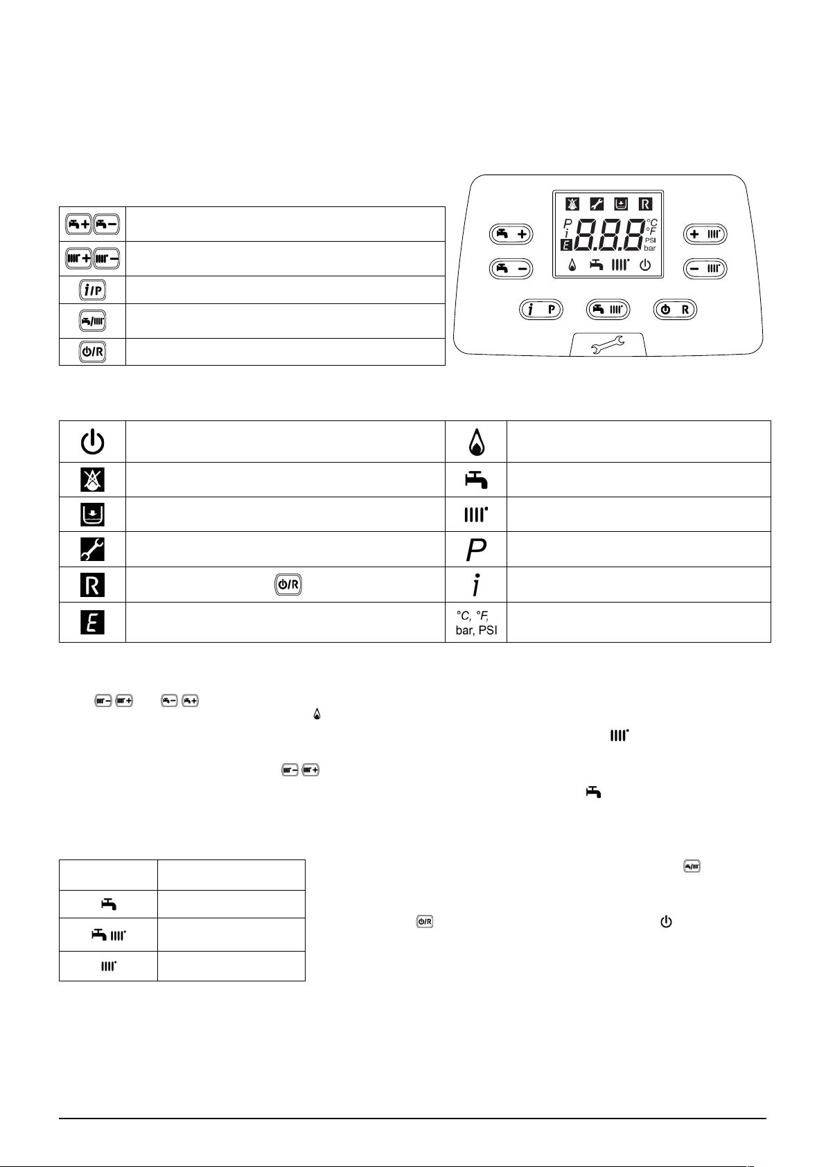
Key to BUTTONS
DHW temperature adjustment
(+ to increase the temperature and – to decrease it)
Heating water temperature adjustment
(+ to increase the temperature and – to decrease it)
Boiler operating information
Operating mode:
DHW – DHW & Heating – Heating Only
Off – Reset – Exit menu/functions
Key to SYMBOLS
Off: heating and DHW disabled
(only boiler anti-freeze protection is active)
Fault preventing the burner from lighting DHW operating mode enabled
Boiler/system water pressure low Heating mode enabled
Technical Service Centre call-in Programming menu
Manually resettable fault ( )
Fault in progress Set unit of measurement (SI/US)
Burner lit
Boiler information menu
1.1 ADJUSTING THE CH AND DHW FLOW TEMPERATURE
Press and respectively to adjust the CH and DHW ow temperature (if an external storage boiler is tted). When
the burner is lit, the display shows the symbol .
HEATING: while the boiler is operating in the heating mode, the display shows the ashing symbol and the heating delivery
temperature (°C).
When connected to an External Sensor, indirectly adjust the room temperature (factory setting 20°C - see section 11.2.1).
DHW: While the boiler is operating in the DHW mode, the display shows the ashing symbol and the primary boiler circuit
temperature (°C).
1.2 OPERATING MODES
USER Section (en)
SYMBOL
DISPLAYED
OPERATING MODE
DHW
DHW & HEATING
HEATING ONLY
To enable the appliance in DHW - Heating or Heating only press
and choose one of the three available modes.
To disable the boiler operating modes whilst keeping the anti-freeze function
enabled, press
display (the display backlighting ashes if the boiler is blocked).
for at least 3 seconds. Just the symbol appears on the
5
7679775.01 (1-04/17)
repeatedly
Page 6
2. PROLONGED SHUTDOWN. ANTI-FREEZE PROTECTION
Do not drain the whole system as lling up with water again could cause unnecessary and harmful scale to build up inside the
boiler and the heating elements. If the boiler is not used during winter and is therefore exposed to the danger of frost, add some
specic anti-freeze to the water in the system (e.g.: propylene glycol coupled with corrosion and scale inhibitors). The electronic
boiler management system includes a “frost protection” function for the heating system which, when delivery temperature falls
below 5°C, lights the burner until a delivery temperature of 30°C is reached.
The function is operative if: the boiler is electrically powered, there is gas, system pressure is normal and the boiler is not
blocked.
3. GAS CONVERSION
The boilers can operate both on natural gas (G20) and LPG (G31). All gas conversions must be made by the AUTHORISED
TECHNICAL SERVICE CENTRE.
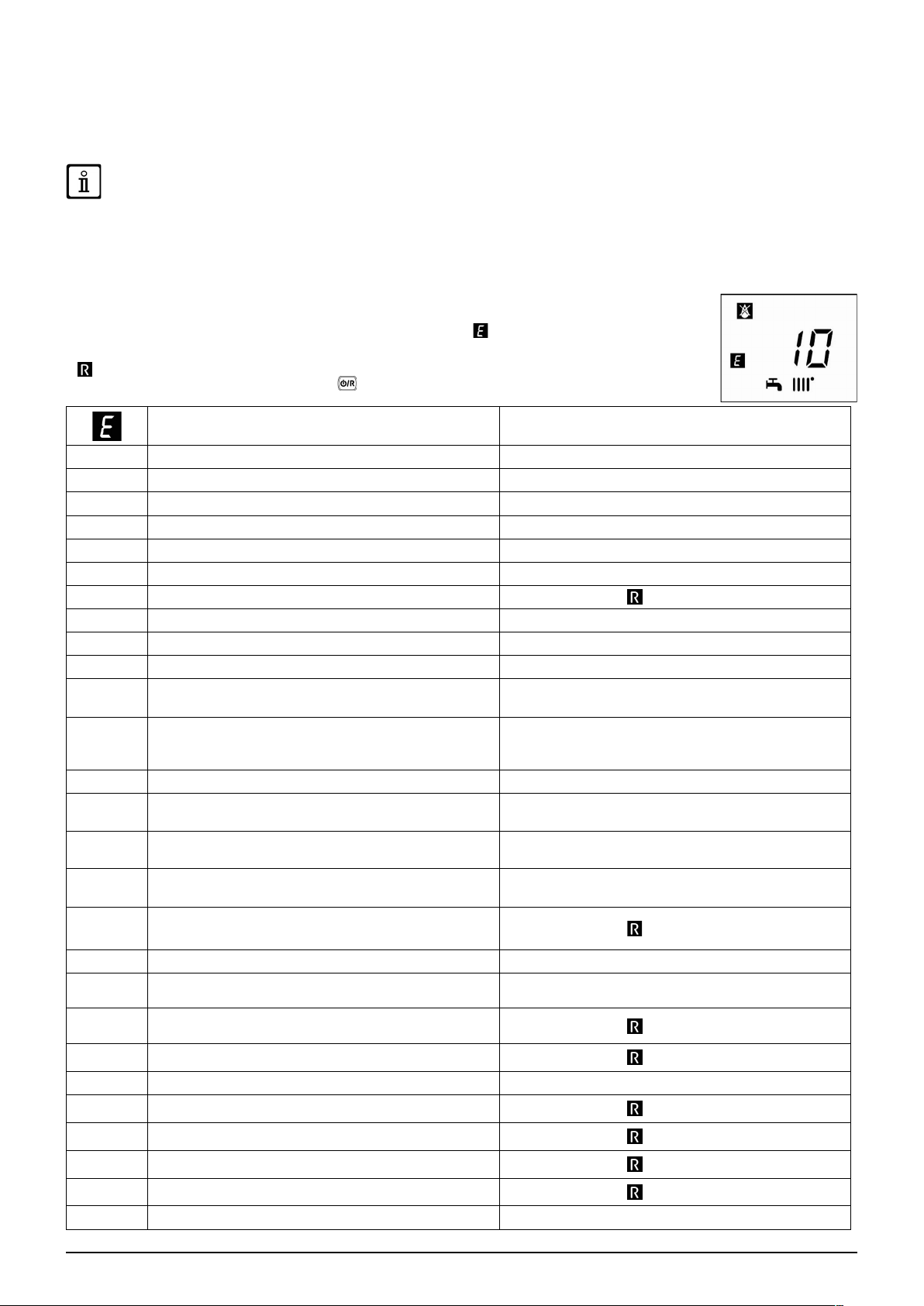
4. FAULTS
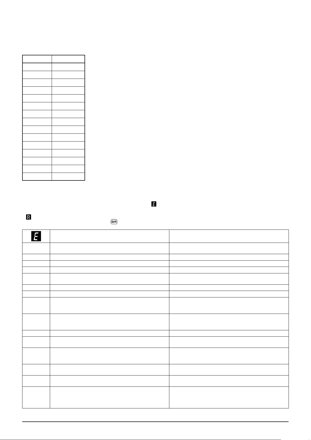
The faults shown on the display are identied with the symbol and a number (fault code). For a
complete list of faults, see the following table.
If appears on the display the fault must be RESET by the user.
To RESET the boiler, press and hold down for 2 seconds. If faults are displayed frequently, call the
Authorised Service Centre.
Description of fault Action
09
10
12
13
15
18
19
20
28
40
50
53
55
83…87
USER Section (en)
92
109
110
117
118
125
128
129
130
133
134
135
154
Gas valve connection error Call the Authorised Service Centre.
External probe sensor faulty Call the Authorised Service Centre.
Hydraulic differential pressure switch switching failure Call the Authorised Service Centre.
Hydraulic differential pressure switch contacts stuck Call the Authorised Service Centre.
Gas valve control error Call the Authorised Service Centre.
Hydraulic circuit automatic lling in progress Wait for the end of the lling cycle
Fault in system lling phase
NTC ow sensor faulty Call the Authorised Service Centre.
NTC fumes sensor faulty Call the Authorised Service Centre.
NTC return sensor faulty Call the Authorised Service Centre.
NTC domestic hot water sensor faulty
(only for heating-only model with storage boiler)
Press and hold down
Call the Authorised Service Centre.
for at least 2 seconds.
Disconnect the boiler from the mains power supply
Fumes outlet obstructed
Electronic board not calibrated Call the Authorised Service Centre.
Communication problem between boiler board and control
unit. Probable short circuit on wiring.
Fumes fault during calibration (probable fumes
recirculation)
Air in boiler circuit
(temporary fault)
Safety thermostat tripped due to overtemperature (pump
probably blocked or air in heating circuit).
Pressure in hydraulic circuit too high (> 2,7 bar) Call the Authorised Service Centre.
Pressure in hydraulic circuit too low
No circulation safety trip
(control performed via a temperature sensor)
No ame
Loss of ame at ignition Call the Authorised Service Centre.
Fumes NTC tripped due to overtemperature
Ignition failure (5 attempts)
Gas valve blocked
Internal board error
Delivery/return probe control test Call the Authorised Service Centre.
for a few seconds.
technical service centre
Call the Authorised Service Centre.
Call the Authorised Service Centre.
Call the Authorised Service Centre.
Press and hold down
Check that the pressure in the system is correct; See the
FILLING THE SYSTEM section.
Press and hold down
Press and hold down
Press and hold down
Press and hold down
Press and hold down
Press and hold down
If the fault persists, call the authorised
for at least 2 seconds.
for at least 2 seconds.
for at least 2 seconds.
for at least 2 seconds.
for at least 2 seconds.
for at least 2 seconds.
for at least 2 seconds.
7679775.01 (1-04/17) 6
Page 7
160
178
270
317 162
321 163
384 164
385 165
431
Fan fault Call the Authorised Service Centre.
Intervention of safety thermostat for excess temperature in
low temperature system
Overheating exchanger Call the Authorised Service Centre.
Call the Authorised Service Centre. Call the Authorised Service Centre.
Call the Authorised Service Centre. Call the Authorised Service Centre.
Parasite ame (internal error)
Input voltage too low
Exchanger sensor faulty Call the Authorised Service Centre.
In the event of a fault, the display backlighting indicates the error code. 5 reset attempts can be performed after which the
boiler shuts down. Wait 15 minutes before attempting to reset the boiler again.
Call the Authorised Service Centre.
Press and hold down
Automatic reset at voltages in excess of 175V. If this fault
persists, call the Authorised Service Centre.
for at least 2 seconds.
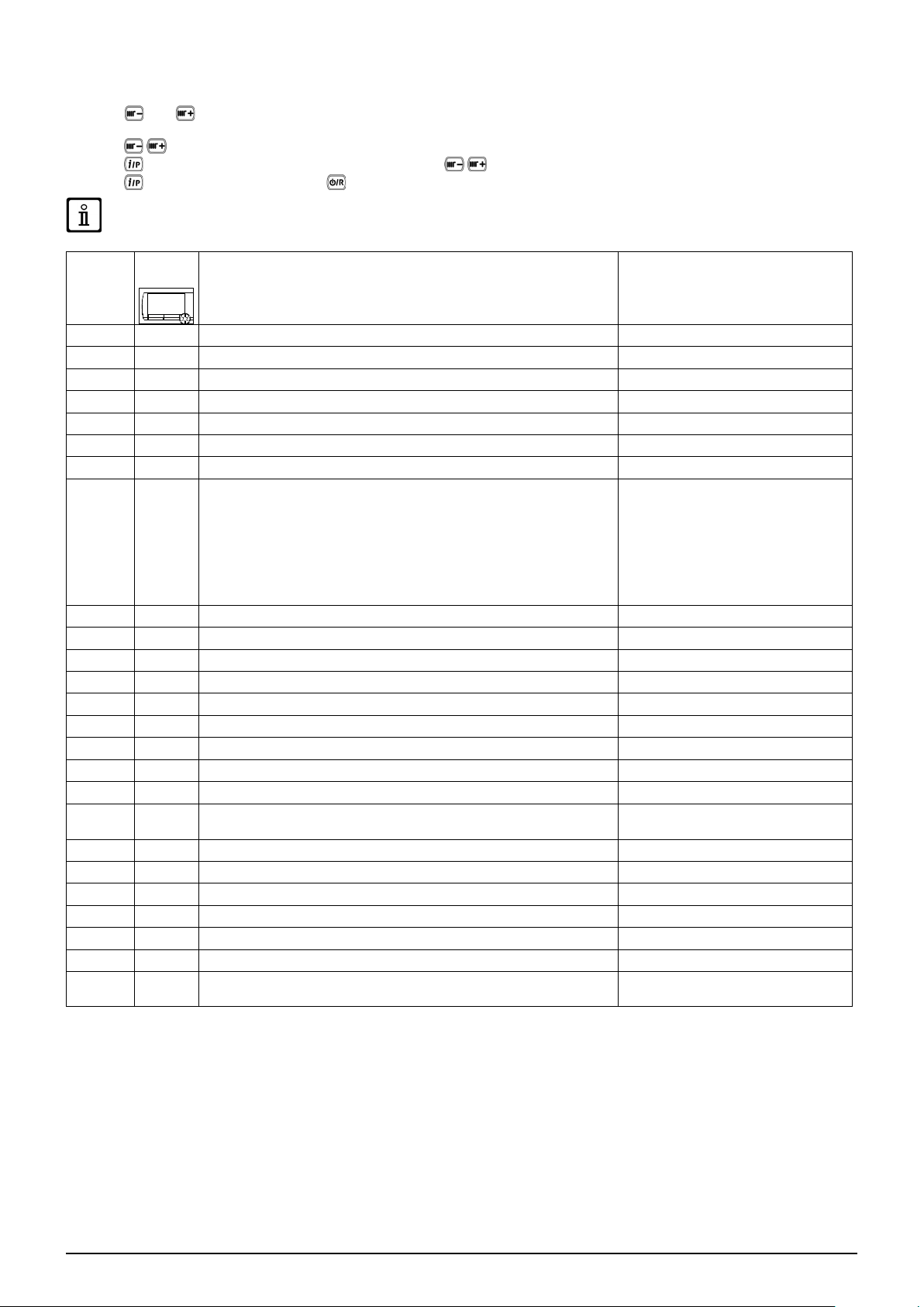
5. BOILER INFORMATION MENU
Press and hold down for at least 1 second, to display the information indicated in the table. Press to exit.
DESCRIPTION DESCRIPTION
00 Secondary fault internal code 06 Heating return temperature (°C)
01 Heating supply temperature (°C) 07 Flue sensor temperature (°C)
02 Outdoor temperature (°C) 08 Primary exchanger temperature (°C)
03 Indirect tank DHW temperature (boiler CH only) 09 - 13 Manufacturer information
04
Domestic hot water temperature
(boiler with plate exchanger)
14 Identication Open Therm communication
05 Water pressure in heating system (bar) 15 - 18 Manufacturer information
6. SWITCHING OFF THE BOILER
To turn off the boiler, disconnect the electric power supply using the two-pole switch. In the “Off” operating mode the boiler stays
off but the electrical circuits remain powered and the anti-freeze function remains active.
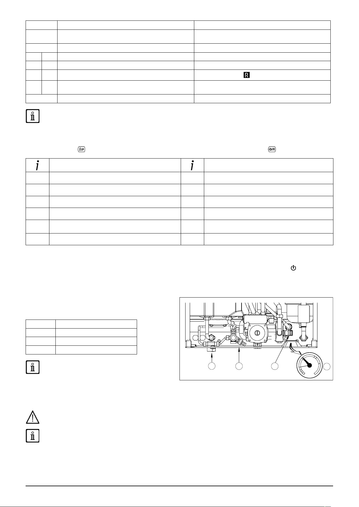
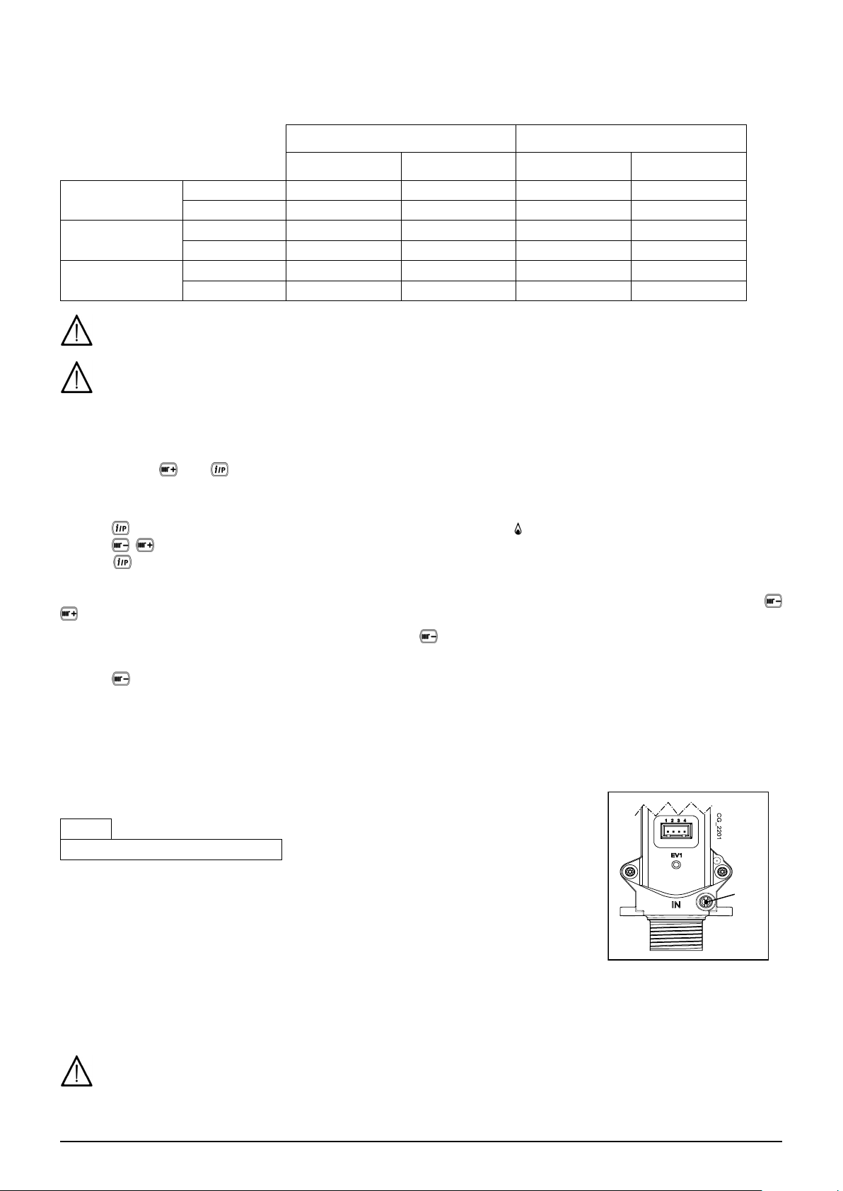
7. FILLING THE SYSTEM
Regularly check that the pressure displayed on the pressure
gauge "D" is 1 - 1.5 bar, with the boiler cold. If the pressure is
too low, turn tap "A" to ll the boiler (gure to side).
A Boiler lling tap
B Storage boiler drain tap
C Boiler drain tap
D Pressure gauge
USER Section (en)
Take special care when lling the heating system. In
particular, open any thermostat valves in the system,
the formation of air inside the primary circuit until operating
pressure is reached. Lastly, vent any radiators in the system.
De Dietrich declines all liability for damage deriving from the
presence of air bubbles in the primary exchanger due to the
incorrect or imprecise observance of the above.
ensure the water enters slowly in order to prevent
The boiler is tted with a hydraulic pressure gauge which prevents the boiler from working if there is no water.
If pressure drops occur frequently, have the boiler checked by the AUTHORISED TECHNICAL SERVICE CENTRE .
8. ROUTINE MAINTENANCE INSTRUCTIONS
To keep the boiler efcient and safe, have it checked by the Authorised Service Centre at the end of every operating period.
Careful servicing ensures economical operation of the system.
7
7679775.01 (1-04/17)
Page 8
INSTRUCTIONS PRIOR TO INSTALLATION
The following notes and instructions are addressed to installers to allow them to carry out trouble-free installation. Instructions for
igniting and using the boiler are contained in the "Instructions for Users" section. The installation must satisfy the requirements of
UNI and CEI standards and local by-laws and technical regulations.
Moreover, the installation technician must be qualied to install heating appliances. Additionally, bear in mind the following:
• When installing the unit in environments with temperatures lower than 0°C, take the necessary precautions to avoid the
formation of ice in the siphon and in the condensation drain.
• The boiler can be used with any kind of convector plate, radiator or thermoconvector. Design the system sections as usual,
though, bearing in mind the available capacity-head at the plate (see annex "SECTION" E at the end of this manual).
• Initial ignition of the boiler must be carried out by the Authorised Service Centre (as indicated on the attached sheet).
Failure to observe the above will render the warranty null and void.
Do not leave any packaging (plastic bags, polystyrene, etc.) within the reach of children as they are a potential source of danger.
9. INSTALLING THE BOILER
The template outline is shown in annex "SECTION" C at the end of this manual.
After deciding the exact location of the boiler, x the template to the wall. Connect the system to the gas and water inlets present
on the lower bar of the template. Make sure the rear part of the boiler (back) is as parallel as possible to the wall (otherwise,
shim the lower part). Fit two G3/4 taps (ow and return) on the central heating circuit; these taps make it possible to carry out
important operations on the system without draining it completely. If you are either installing the boiler on an existing system or
replacing one, as well as the above, t a settling tank under the boiler on the system return line in order to collect any deposits
and scale circulating in the system after ushing. After xing the boiler to the template, connect the ue and air ducts, supplied
as accessories, as described in the following sections. Connect the siphon to a drain trap, making sure the slope is continuous.
Avoid horizontal stretches.
Do not lift the boiler exerting pressure on the plastic parts like the siphon and the ue turret.
Tighten the boiler water connections with care (maximum tightening torque 30 Nm).
Before starting up the boiler, ll the water siphon to prevent the fumes from diffusing in the room.
9.1 CONTENTS OF PACK
• Template (see gure in attachment "SECTION" C)
• Boiler support bar
• 8 mm expansion grips and pressure screws
• Condensation discharge pipe
ACCESSORIES supplied on request:
• Heating system ow/return taps, water input tap and telescopic joints
• Gas tap
9.2 BOILER DIMENSIONS AND GAS WATER CONNECTIONS
The dimensions of the boiler and the relative installation positions of the water connections are shown in the annex "SECTION"
C at the end of the manual.
INSTALLER Section (en)
7679775.01 (1-04/17) 8
Page 9
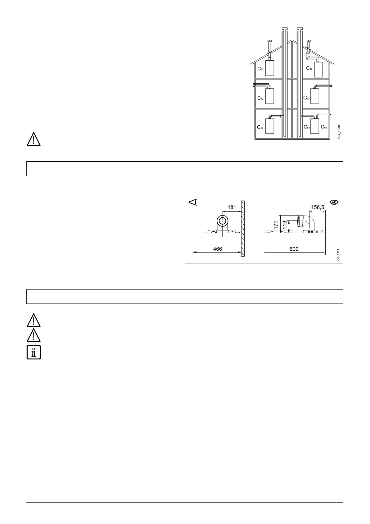
10. INSTALLING THE FLUE
The boiler is easy and exible to install thanks to the extensive range of available
accessories, as described below. The boiler has been designed for connection to a
vertical or horizontal coaxial ue-air duct. The boiler can also be used with separate
ducts using the accessory splitting kit.
WARNINGS
C13, C33 The terminals for separate ues must be tted inside a 50 cm square. Detailed
instructions are provided with the individual accessories.
C53 Do not t the ue and air duct terminals on opposite walls of the building.
C63 The pressure drop of the ducts must not exceed 100 Pa. The ducts must be certied
for this specic use and for a temperature in excess of 100°C. The ue terminal must be
certied to EN 1856-1.
C43, C83 The ue terminal or ue duct must be suitable for the purpose.
To optimise operating safety, make sure the ue ducts are rmly xed to the wall
with suitable brackets. The brackets must be positioned over the joints at a distance
of approximately 1 metre from one another.
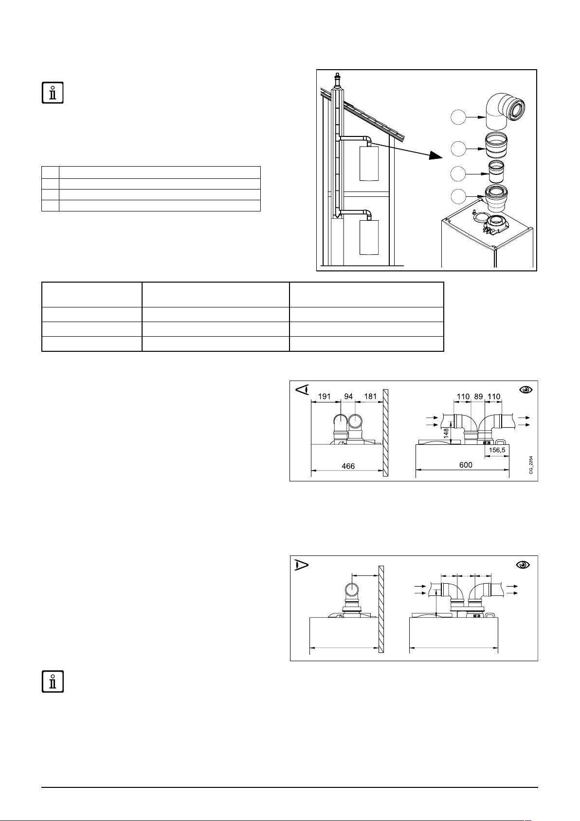
10.1 CONCENTRIC DUCTS
This type of duct is used to discharge exhaust fumes and draw
combustion air both outside the building and if a LAS ue is
tted. The 90° coaxial bend allows the boiler to be connected
to a ue-air duct in any direction as it can be rotated by 360° It
can also be used as a supplementary curve combined with a
coaxial duct or a 45° curve.
If fumes are discharged outside the building, the ue-air
duct must protrude at least 18 mm from the wall to allow an
aluminium weathering surround to be tted and sealed to avoid
water inltrations.
• A 90° bend reduces the total duct length by 1 metre.
• A 45° bend reduces the total duct length by 0.5 metres.
• The rst 90° bend is not included when calculating the maximum available length.
Read carefully the venting instructions contained in this manual and the ones supplied by the vent manufacturer, in
case of discrepancies the venting instruction of this manual must be respected.
Fasten the suction pipes using two galvanised Ø 4,2 mm self tapping screws with minimum length 19 mm. If not
included with the supply, screws with the same characteristics must be sourced on the market separately.
INSTALLER Section (en)
Before securing the screws, make sure that at least 45 mm of the pipe is inserted into the gasket (see the gures in annex
"SECTION" D at the end of this manual).
Make sure there is a minimum downward slope of 5 cm per metre of duct towards the boiler.
SOME OUTLET DUCT INSTALLATION EX AMPLES AND THEIR RELATIVE MAXIMUM LENGTHS ARE SHOWN IN ANNEX
"SECTION" D AT THE END OF THIS MANUAL.
9
7679775.01 (1-04/17)
Page 10
10.1.1 C43P EXHAUST TYPE
Collective positive pressure ue pipe for sealed chamber boilers
This type of installation is only possible with natural gas
boilers (G20)
In order to connect the boiler to a C43P collective ue pipe, the nonreturn valve is required.
The sizing of the ue pipe is dened by the conduit supplier in
accordance with EN 13384-2.
1 90° elbow Ø 80/125 mm
2 Conduit Ø 80/125 mm
3 Non-return valve Ø 80 mm
4 Adaptor Ø 60/100 -> 80/125 mm
For this type of installation, it is necessary to modify the P71 and P72
parameters in the electronic card as shown in the table (also see the
SERVICE instructions).
After changing the parameters, the boiler must be calibrated as
described in the SERVICE manual.
Model
MPX 24 - MPX 20/24 MI 85 130
MPX 24/28 MI 85 185
MPX 28/33 MI 85 180
Qmin - Pressure at the chimney 25 Pa
P72
Qmax - Pressure at the chimney 86 Pa
10.2 SEPARATE DUCTS
This type of installation makes it possible to discharge exhaust
fumes both outside the building and into single ue ducts.
Comburent air can be drawn in at a different location from that
of the ue terminal. The accessory splitting kit comprises a ue
duct adaptor (80) (B) and an air duct adaptor (A). For the air
duct adaptor, t the screws and seals previously removed from
the cap.
The 90° bend is used to connect the boiler to the inlet and
outlet ducts, adapting them to various requirements. It can also
be used as a supplementary curve combined with a duct or a
45° bend.
• A 90° bend reduces the total duct length by 0.5 metres.
• A 45° bend reduces the total duct length by 0.25 metres.
• The rst 90° bend is not included when calculating the maximum available length.
SINGLE SPLITTING KIT (ALTERNATIVE ACCESSORY)
For special installations of the fumes inlet/outlet ducts, the
single splitting kit (C), supplied as an accessory, can be used.
INSTALLER Section (en)
This accessory, in fact, can be used to move the inlet and outlet
in any direction. This type of installation makes it possible to
discharge exhaust fumes both outside the building and into
single ue ducts. Comburent air can be drawn in at a different
location from that of the ue terminal. The splitting kit is xed
to the boiler turret (100/60 mm) and allows the comburent air
and outlet fumes to enter/leave the two separate ducts (80
mm). For further information, read the assembly instructions
supplied with the accessory.
SOME OUTLET DUCT INSTALLATION EX AMPLES AND THEIR RELATIVE MAXIMUM LENGTHS ARE SHOWN IN ANNEX
"SECTION" D AT THE END OF THIS MANUAL.
P71
AB
7679775.01 (1-04/17) 10
Page 11
11. ELECTRICAL CONNECTIONS
This machine is only electrically safe if it is correctly connected to an efcient earth system in compliance with current safety
regulations. Connect the boiler to a 230V single-phase earthed power supply using the supplied three-pin cable, observing correct
Live-Neutral polarity.
Use a double-pole switch with a contact separation of at least 3 mm.
When replacing the power supply cable, t a harmonised “HAR H05 VV-F” 3x0.75 mm2 cable with a maximum diameter of 8 mm.
The 2A fast-blowing fuses are incorporated in the power supply terminal block (to check and/or replace the fuse, pull out the black
fuse carrier).
Rotate the control box downwards and access terminal blocks M1 and M2, used for the electrical connections, by removing the
safety cover.
Make sure that the overall rated power input of the accessories connected to the appliance is less than 2A. If it is higher, install
a relay between the accessories and the electronic board.
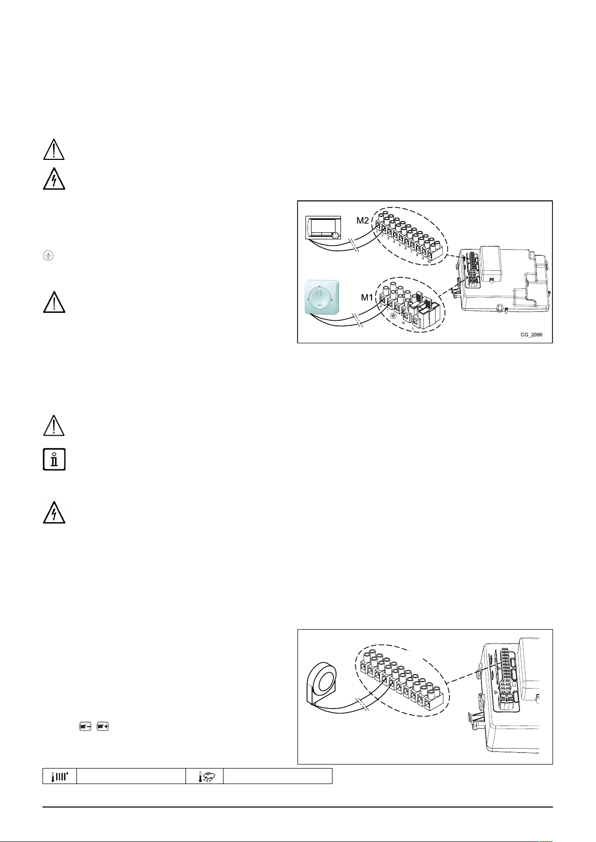
Terminal block M1 is at high voltage. Before making connections, make sure the appliance is disconnected from the power
supply.
TERMINAL BLOCK M1
(L) = Live (brown)
(N) = Neutral (light blue).
= Earth (yellow-green).
(1) (2) = contact for Room Thermostat.
Put back the jumper on terminals 1-2 of boiler terminal
block M1 if the room thermostat is not used or if the
Remote Control, supplied as an accessory, is not
installed.
TERMINAL BLOCK M2
Terminals 1 - 2: connection to the Remote Control (low voltage) supplied as an accessory.
INSTALLER Section (en)
Terminals 4 - 5 : external Probe connection (supplied as an accessory)
Terminals 3-6-7-8-9-10 : not used.
If the appliance is connected to an underoor system, install a limit thermostat to prevent the latter from overheating.
Use the relative cable grommets at the bottom of the boiler to thread the cables through to the terminal blocks.
11.1 CONNECTING THE ROOM THERMOSTAT
The connections in terminal block M1 are high voltage (230 V). Before making connections, make sure the appliance is
disconnected from the power supply. Respect polarity L (LIVE) - N (NEUTRAL).
To connect the Room Thermostat to the boiler, proceed as described below:
• switch off the boiler;
• access the terminal block M1;
• remove the jumper from the ends of contacts 1-2 and connect the wires of the Room Thermostat;
• switch on the boiler and make sure the Room Thermostat works correctly.
11.2 ACCESSORIES NOT INCLUDED IN THE SUPPLY
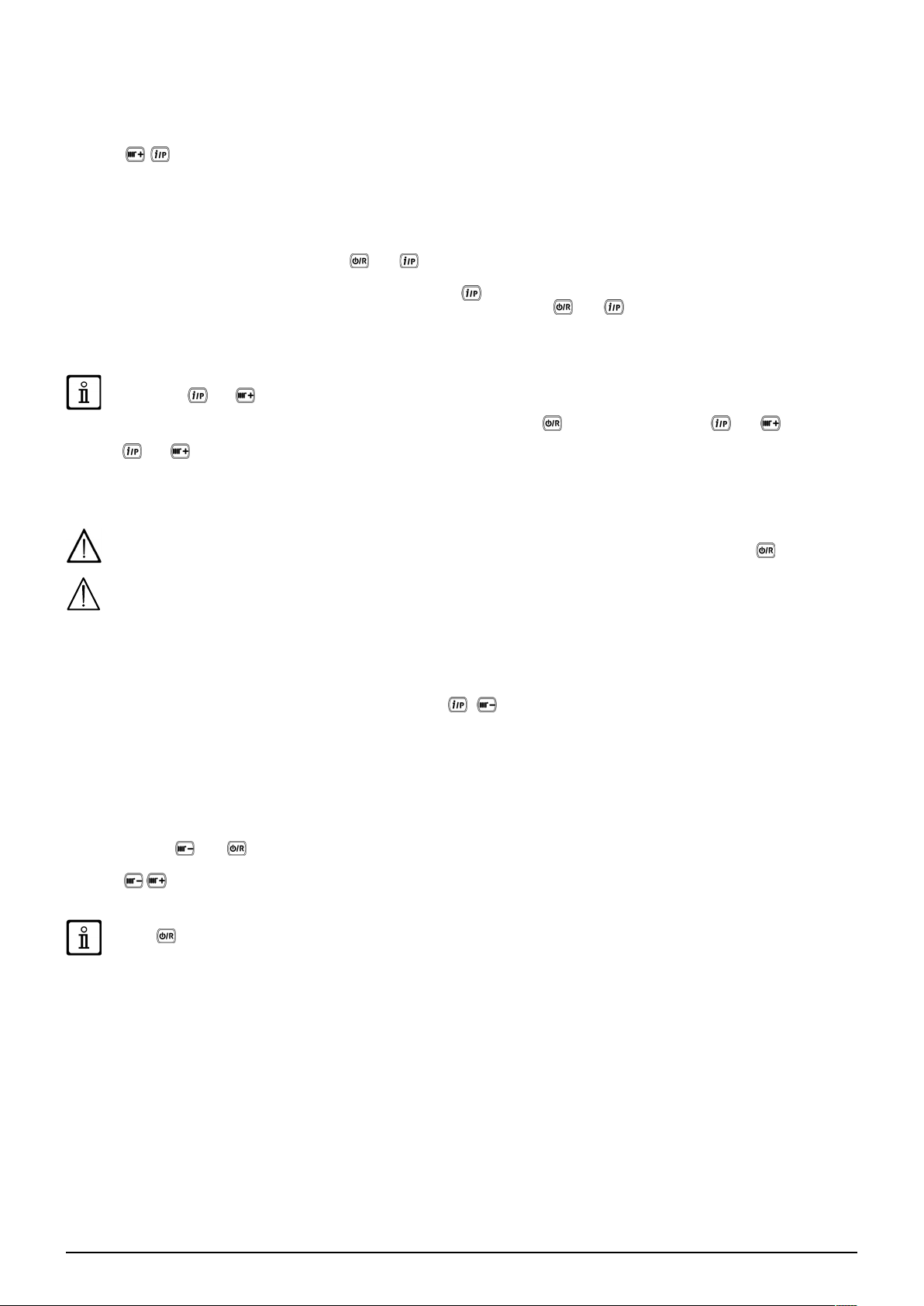
11.2.1 EXTERNAL SENSOR
To connect this accessory, see gure to side (terminals 4-5)
and the instructions supplied with the sensor.
SETTING THE "Kt" CLIMATE CURVE
When the external sensor is connected to the boiler, the
electronic board adjusts the ow temperature calculated
according to the set Kt coefcient. Select the required curve by
pressing
E for selecting the most appropriate one (00 to 90).
KEY TO CHART - “SECTION” E
as indicated in the chart in annex SECTION
Flow temp Outside temp
11
7679775.01 (1-04/17)
Page 12
12. SPECIAL FUNCTIONS
12.1 INITIAL IGNITION
When lighting the boiler for the rst time perform the following procedure. After electrically powering the boiler the code "000"
appears on the display. This means the appliance is ready for the "initial lighting" procedure.
• Press together and hold down for 6 seconds. "On" appears on the display for 2 seconds followed by code "312"
indicating that the "system venting" function is active. This function lasts 10 minutes.
• Afterwards, the boiler switches on, the display shows the code "000" alternating with the % of ignition power and the temperature
value (°C). During this "gas recognition function" phase, that lasts approximately 7 minutes, the type of gas used is analysed.
During this function, assure maximum heat exchange to the heating or DHW system (domestic hot water demand) in order to
prevent the boiler from switching off due to overheating.
• If the boiler runs on natural gas, the display shows NG for approximately 10 seconds. The boiler is now ready for normal
operation. If the display shows LPG, press
the factory setting.
• If the boiler runs on propane the display shows LPG. Press
the display shows NG and does not recognise the type of gas used, press and together and hold down for at least 4
seconds to exit the function and then change parameter P02=01 as described in the “PARAMETER SETTINGS” section of the
boiler instructions manual.
If the venting or gas recognition function is interrupted by a power blackout, start the function again when power is restored
by pressing and together and holding them down for at least 6 seconds. If the display shows fault E118 (low pressure
gas recognition function is interrupted due to a fault (e.g.: E133 no gas) press to reset and then press and (for at least
6 seconds) to restart the function again. If the gas recognition function is interrupted due to overheating, restart the function by
pressing and and holding them down for at least 6 seconds.
The combustion of this appliance has been factory controlled, calibrated and set for operation with NATURAL GAS.
During the Gas Type Control Function, the combustion ratio will increase for a short period of time while the gas type is being
established.
in hydraulic circuit) during the venting function, open the lling tap on the appliance and restore the correct pressure. If the
During initial ignition, the burner may not ignite (causing the boiler to shut down) until any air in the gas pipes is vented.
In this case, repeat the ignition procedure until gas reaches the burner. To reset boiler operation, press
seconds.
and together and hold down for at least 4 seconds to exit without changing
for at least 6 seconds to conrm the gas effectively used. If
for at least 2
For the rst few ignitions immediately after installation the system must implement a self-learning procedure to reach the
correct ignition level.
12.2 SYSTEM GAS EXTRACTION FUNCTION
This function is used to facilitate the elimination of the air inside the heating circuit when the boiler is rst installed or after
maintenance when the water is drained from the primary circuit.
To enable the system gas extraction function press buttons together for 6 seconds. When the function is active, On
appears on the display for a few seconds, followed by programme row 312.
The electronic board will activate a pump on/off cycle lasting 10 minutes. The function will automatically stop at the end of the
cycle. To manually exit this function, press the above buttons together for 6 seconds once again.
12.3 CHIMNEY SWEEPER
This function enables the boiler to generate maximum heating power. After activation, the boiler power % can be adjusted from
minimum to maximum in the DHW mode. The following procedure is used.
• Press buttons and together for at least 6 seconds. When the function is enabled, the displays shows “On” for a few
seconds followed by programme row “303” alternated with the % of boiler power.
• Press
• To exit press both buttons together for at least 6 seconds, as described in point one.
INSTALLER Section (en)
to gradually adjust power (sensitivity 1%).
Press to display the instantaneous ow temperature for 15 seconds.
7679775.01 (1-04/17) 12
Page 13
12.4 COMBUSTION TEST (CO2)
For correct boiler operation, the content of (CO2- O2) in the combustion fumes must observe the tolerances indicated in the
following table. If the value of (CO2- O2) is different, check the electrodes and their relative distances. If necessary, replace the
electrodes and position them correctly. If the problem persists, use the following function.
G20 G31
% O2 % CO2 % O2 %
CO
2
Maximum power
Ignition power
Minimum power
The combustions analisys shall be done using an analyzer regularly calibrated.
During normal operation the boiler per forms combustion control cycles. In this phase, CO values higher than 1000 ppm can
occur for brief periods of time.
Nominal value 8.7 5.4 10.0 6.0
Permitted value 8.2 - 9.3 6.3 - 4.3 9.5 - 10.5 6.8 - 5.2
Nominal value 8.7 5.4 10.8 4.8
Permitted value 8.2 - 9.3 6.3 - 4.3 10.3 - 11.3 5.5 - 4.1
Nominal value 8.8 5.2 10.0 6.0
Permitted value 8.2 - 9.3 6.3 - 4.3 9.5 - 10.5 6.8 - 5.2
COMBUSTION ADJUSTMENT FUNCTION (CO2%)
This function sets out to partially adjust the value of CO2%. The following procedure is used.
• Press buttons and together for at least 6 seconds. When the function is enabled, the displays shows “On” for a few
seconds followed by programme row “304” alternated with the % of boiler power.
• After the burner is lit, the boiler reverts to maximum DHW power (100). When the display shows "100" it is possible to partially
adjust the value of CO
• press
• press
• press
. The display shows "00" alternating with the function number "304" ( ashes);
to raise or lower the amount of CO2 (from -3 to +3).
to save the new value and view the power value "100" on the display again (the boiler continues operating at
maximum DHW power).
This procedure can also be used to adjust the quantity of CO2 to the ignition power and to the minimum power by pressing
after point 5 of the procedure described above.
• After saving the new value (point 5 of the procedure), press to take the boiler to its ignition power. Wait for the value of
CO2 to stabilise and then adjust as described in point 4 of the procedure (the power value is a number <> 100 and <> 0) then
save (point 5).
• press
again to take the boiler to minimum power. Wait for the value of CO2 to stabilise and then adjust as described in
point 4 of the procedure (power value = 00);
• to exit the function, press the buttons for at least 6 seconds as described in point 1.
2
%;
13. GAS VALVE
This appliance does not require any mechanical adjustment on the valve. The system ensures electronic auto-adaptation.
Gas valve key
Pi
Gas supply inlet pressure tap
INSTALLER Section (en)
Pi
13.1 GAS CONVERSION METHODS
Only an Authorised Technical Assistance Service can convert boiler operation from NATURAL GAS to LPG or vice-versa. To
perform calibration, set parameter P02 as described in the PARAMETER SETTINGS section. Lastly, check the combustion
parameters as described in the SPECIAL FUNCTIONS - CHECKING COMBUSTION PARAMETERS section.
When the gas change is completed the boiler data plate must be amended to indicate the new gas data.
13
7679775.01 (1-04/17)
Page 14
14. PARAMETERS SETTING
To programme the parameters of the boiler electronic board, proceed as follows:
• Press and together and hold them down for 6 seconds until programme row “P01” appears on the display alternated
with the set value;
• Press
• Press
• Press
Boiler
P01 P00 Manufacturer information 00
P02 P01 Gas used 00 = METHANE - 01 = LPG 00
P03 P02 Hydraulic system 06
P04 P03 Programmable relay 1 settings (See SERVICE instructions) 02
P05 P04 Programmable relay 2 settings (See SERVICE instructions) 04
P06 P05 External probe input conguration (See SERVICE Instructions) 00
P07..P09 P06..P08 Manufacturer information --
to scroll the list of parameters;
the value of the selected begins ashing, press to change the value;
to conrm the value or press to exit without saving.
Further information concerning the parameters listed in the following table are supplied together with the required
accessories.
Remote
control*
Heating setpoint setting OT / RT
(Remote Control - Open Therm / Room Thermostat 230V~)
DESCRIPTION OF PARAMETERS FACTORY SETTINGS
P10 P09
P11..P12 P10..P11 Manufacturer information --
P13 P12 Max. heating output (0-100%) 80
P14 P13 Max DHW output (0-100%) 100
P15 P14 Min. heating output (0-100%) 00
P16 P15 Maximum CH setpoint (°C) 00 = 85°C - 01 = 45°C 00
P17 P16 Pump overrun time in heating mode (01-240 minutes) 03
P18 P17 Delay prior to new ignition in CH mode (00-10 minutes) - 00=10 seconds 03
P19 P18 Manufacturer information 07
P20 P19 Pump overrun time in DHW mode (seconds) 30
P21 P20
P22 P21** Manufacturer information 00
P23 P22 Maximum DHW setpoint temperature (ACS) 60
P24 P23 Manufacturer information 35
INSTALLER Section (en)
P25 P24 No water safety device 00
P26..P31 P25..P30 Manufacturer information --
P32..P41 P31..P40 Diagnostics (See SERVICE Instructions) --
P67 P66
* The modulating remote control must version 2.8 or higher
** Access to the installer settings using the modulating remote control is not possible
00 = the temperature request is the Remote Control setpoint
01 = the temperature Request is the highest setpoint between Remote
Control and PCB
02 = the temperature request is the Remote Control setpoint.
The Room Thermostat enable the gas boiler operates
Anti-legionellosis function (°C) 00…54 = Disabled - 55…67 = Enabled
(set the desired temperature value)
Open Therm (OT) settings (See SERVICE Instructions
02 = Open Therm Standard
)
00
00
02
7679775.01 (1-04/17) 14
Page 15
14.1 ADJUSTING MAXIMUM HEATING POWER
The maximum heating power of the boiler can be reduced to suit the requirements of the heating system it serves. A table showing
parameter P13 values according to the desired maximum power model is shown below for each single boiler
To access and edit parameter P13 values, proceed as described in the PARAMETER SETTINGS section.
Boiler model - PARAMETER P13 (%) / Heating output (kW)
kW 28/33
5 0
6 4
7 7
8 11
9 14
10 18
12 25
14 32
16 39
18 46
20 54
22 61
24 68
26 75
28 80
INSTALLER Section (en)
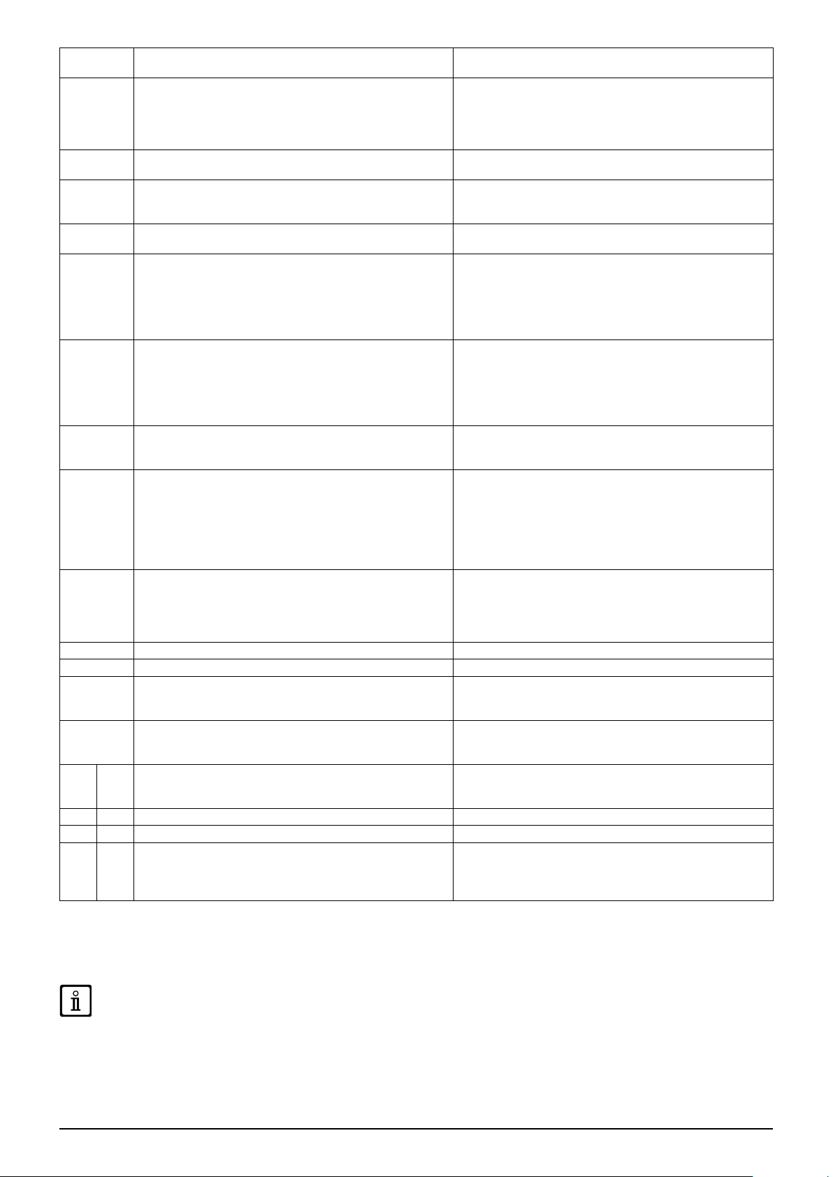
15. TROUBLESHOOTING SERVICE FAULTS
The faults shown on the display are identied with the symbol and a number (fault code). For a complete list of faults, see the
following table.
If appears on the display the fault must be RESET by the user.
To RESET the boiler, press and hold down for 2 seconds. If faults are displayed frequently, call the Authorised Service Centre.
Description of fault Service action
09
10
12
13
15
18
19
20
28
40
50
53
55
83…87
92
Gas valve connection error
External probe sensor faulty Check the sensor (*).
Hydraulic differential pressure switch switching failure Check correct operation of the pressure switch and the wiring.
Hydraulic differential pressure switch contacts stuck See the actions indicated in E12
Gas valve control error
Hydraulic circuit automatic lling in progress Wait for the end of the lling cycle.
Fault in system lling phase Check the lling tap.
NTC ow sensor faulty
NTC fumes sensor faulty
NTC return sensor faulty See the actions indicated in E20
NTC domestic hot water sensor faulty (only for heating-only
model with storage boiler)
Fumes outlet obstructed
Electronic board not calibrated
Communication problem between boiler board and control unit.
Probable short circuit on wiring.
Fumes fault during calibration (probable fumes recirculation)
Check the connections between the gas valve and the
electronic board.
Check the connections between the gas valve and the
electronic board. If necessary, replace the electronic board.
Check the sensor (**).
Check the continuity of the probe wiring.
Make sure the wiring has not shorted.
Check the fumes NTC probe (***).
Check the continuity of the probe wiring.
Make sure the wiring has not shorted.
See the actions indicated in E20
Check that the drainage pipe is free from obstructions.
Switch off the electric power supply to the boiler for a few
seconds.
Activate the automatic calibration function described in the
spare parts instructions sheet.
Check the wiring between the Ambient Unit and the electronic
board or RF link.
Check for any recirculation of fumes.
Activate the automatic calibration function described in
the paragraph YEARLY MAINTENANCE – REPLACING
COMPONENTS.
15
7679775.01 (1-04/17)
Page 16
109
110
117
118
125
128
129
130
133
134
135
154
160
178
317 162
321 163
INSTALLER Section (en)
384 164
385 165
Air in boiler circuit (temporary fault)
Safety thermostat tripped due to overtemperature (pump
probably blocked or air in heating circuit).
Pressure in hydraulic circuit too high (> 2.7 bar)
Pressure in hydraulic circuit too low
No circulation safety trip.
(control performed via a temperature sensor)
No ame
Loss of ame at ignition
Fumes NTC tripped due to overtemperature
Ignition failure (5 attempts)
Gas valve blocked
Internal board error Replace the electronic board.
Delivery/return probe control test See the actions indicated in E109
Fan fault
Intervention of safety thermostat for excess temperature in low
temperature system
Incorrect power supply frequency
NTC domestic hot water sensor faulty See the actions indicated in E20
Parasite ame (internal error) Check correct operation of the gas valve.
Input voltage too low
Check pump operation.
Check the pump power input wiring.
Check pump operation.
Check the pump power input wiring
Check that the limit thermostat is undamaged and replace it if
necessary
Check the continuity of the limit thermostat wiring
Check that the pressure in the system is correct
See the FILLING THE SYSTEM section.
If the pressure in the CH circuit is < 0.5 bar, perform lling (see
the FILLING THE SYSTEM section).
Check the hydraulic pressure switch works correctly
See the actions indicated in E109
Check the ame sensing electrode is in good condition
and correctly positioned (see the ANNUAL SERVICING POSITIONING THE ELECTRODES section).
Check the wire is uninterrupted and makes good contact with
the ame sensing electrode and the ignition switch.
See the actions indicated in E92
Check the ame sensing electrode is in good condition
and correctly positioned (see the ANNUAL SERVICING POSITIONING THE ELECTRODES section).
Check the wire is uninterrupted and makes good contact with
the ame sensing electrode and the ignition switch.
Check for any recirculation of fumes.
Check the heat exchange level of the water-fumes exchanger:
possible insufcient circulation or presence of scale.
Check the fumes NTC probe (***).
Check that the gas valve is open and there is no air in the gas
supply circuit.
Check the gas supply pressure.
Check the wire is uninterrupted and makes good contact with
the ame sensing electrode and the ignition switch.
See the actions indicated in E92
Check correct operation of the condensate drainage.
Check the gas supply pressure.
Check the integrity and position of the sensing and ignition
electrodes and their wiring (see the ANNUAL SERVICING POSITIONING THE ELECTRODES section).
If necessary, replace the electronic board.
Check correct operation of the fan.
Check that the fan power supply wiring is connected to the
electronic board.
Check correct operation of the pump and the water circulation
in the low temperature system.
Check the pump power input wiring.
Check whether the incorrect electric power supply frequency
is due to causes outside the boiler, in which case contact the
power supply company.
Input voltage V<175V.
Check whether the power supply reductions are due to
reasons other than the boiler. If so, contact the electricity
provider.
CH = central heating.
(*) External Sensor: cold resistance value: approximately 1 kΩ @ 25° C
(**) NTC delivery, return and DHW sensor: cold resistance value: approximately 10 kΩ @ 25° C (resistance decreases as temperature rises).
(***) NTC fumes probe: cold resistance value: approximately 20 kΩ @ 25° C (resistance decreases as temperature rises).
In the event of a fault, the display backlighting indicates the error code. 5 reset attempts can be performed after which the
boiler shuts down. Wait 15 minutes before attempting to reset the boiler again.
(resistance decreases as temperature rises).
7679775.01 (1-04/17) 16
Page 17
16. ADJUSTMENT AND SAFETY DEVICES
The boiler has been designed in full compliance with European reference standards and in particular is equipped with the following:
• Limit thermostat
Thanks to a sensor placed on the CH ow line, this thermostat interrupts the ow of gas to the burner if the water in the primary
circuit overheats.
It is forbidden to disable this safety device
• NTC fumes sensor
This device is positioned on the fumes-water exchanger. The electronic board stops gas from owing to the burner in case of over
heating.
It is forbidden to disable this safety device
• Flame ionisation detector
The ame sensing electrode guarantees safety of operation in case of gas failure or incomplete ignition of the main burner. In
these conditions, the boiler blocks.
• Hydraulic pressure switch
This device allows the main burner to be ignited only if system pressure is higher than 0.5 bars.
• Pump post-circulation
The electronically-controlled pump post-circulation function lasts 3 minutes and is enabled, in the heating mode, if the ambient
thermostat causes the main burner to go out.
• Antifreeze device
The electronic boiler management system includes an "antifreeze" function for the heating and DHW systems which, when ow
temperature falls below 5° C, operates the burner until a ow temperature of 30° C is reached. This function is enabled when the
boiler is switched on, the gas supply is open and the system is correctly pressurised.
• Anti-block pump function
If no heat demand is received in the heating and/or DHW modes for 24 consecutive hours, the pump will automatically start and
operate for 10 seconds.
• Three-way valve anti-blockage function
If no heat demand is received for a period of 24 hours, the three-way valve performs a complete switching cycle.
• Hydraulic safety valve (heating circuit)
This device is set to 3 bar and is used for the heating circuit. Connect the safety valve to a drain trap. Do not use it to drain the
heating circuit.
• Heating pump pre-circulation
In case of a heat demand in the heating mode, the appliance can pre-circulate the pump before the burner is ignited. This precirculation phase last from a few seconds to a few minutes, depending on the operating temperature and installation conditions.
17. PUMP CAPACITY/ HEAD
This is a high static head pump t for installation on any type of single or double-pipe heating systems. The automatic air valve
incorporated in the pump allows quick venting of the heating system.
KEY TO PUMP CHARTS - "SECTION" E
Q WATER FLOW RATE MIN Minimum speed of modulation
H HEAD MAX Maximum speed of modulation
INSTALLER Section (en)
17
7679775.01 (1-04/17)
Page 18
18. ANNUAL SERVICING
If the boiler was operating, wait for the combustion chamber and pipes to cool down.
Before commencing any maintenance operations, make sure the boiler is disconnected from the power supply. After servicing,
reset the original operating parameters of the boiler if they were changed.
Do not clean the boiler with abrasive, aggressive and/or easily ammable substances (such as petrol, acetone, etc.).
To optimise boiler efciency, carry out the following annual controls:
• Check the appearance and airtightness of the gaskets of the gas and combustion circuits. Replace any worn seals with new
original spares;
• Check the state and correct position of the ignition and ame-sensing electrodes;
• Check the state of the burner and make sure it is rmly xed;
• Check for any impurities inside the combustion chamber. Use a vacuum cleaner to do this;
• Check the pressure of the heating system;
• Check the pressure of the expansion vessel;
• Check the fan works correctly;
• Make sure the ue and air ducts are unobstructed;
• Check for any impurities inside the siphon (for condensation boilers);
• Check the magnesium anode, where present, for boilers tted with storage boilers.
It is advisable not to use the service cap at the base to empty and clean the siphon. Remove the siphon from inside the boiler
and clean it with a jet of water. Fill the siphon with clean water and put back in place, making sure that it is properly connected.
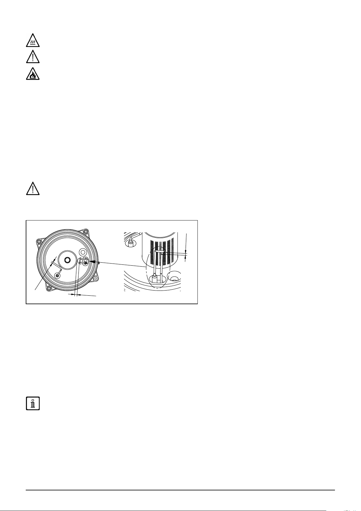
18.1 POSITIONING THE ELECTRODES
5
±0,
4
1
5 ±
1
0
±
1
CG_2190
18.2 REPLACEMENT OF PARTS
If one or more of the following components are replaced:
• Water-fumes exchanger
• Fan
• Gas valve
• Gas nozzle
INSTALLER Section (en)
• Burner
• Flame sensing electrode
perform the Automatic Calibration procedure described below, then check and adjust the CO2% value as indicated in the section
“COMBUSTION ADJUSTMENT FUNCTION (CO2% )”.
When working on the appliance, check the condition and position of the ame sensing electrode and replace it if necessary.
7679775.01 (1-04/17) 18
Page 19
AUTOMATIC CALIBRATION FUNCTION
Press and together and hold down for at least 6 seconds. When the display indicates "On" press (within 3 seconds
after pressing the previous buttons).
If the display indicates "303" the Automatic Calibration function has not been activated. Disconnect the boiler from the mains
power supply for a few seconds and repeat the procedure.
When the function is enabled, and ash on the display
After the ignition sequence, which can also take place after a few attempts, the boiler performs three operations (each lasting
approximately 1 minute) going rst to maximum power, then to ignition power and lastly to minimum power. Before moving on to
the following phase (from maximum power to ignition power and then to minimum power), and appear on the display.During
this phase, the power level reached by the boiler and the delivery temperature alternate on the display.
When , and ash together on the display, the calibration function has terminated.
Press to leave the function. The display shows ESC.
19. DISMANTLING, DISPOSAL AND RECYCLING
Only qualied technicians are authorised to service the device and system.
Before dismantling the appliance, be sure to disconnect the power supply, close the gas inlet shutoff valve and secure all of the
boiler and system connections.
Dispose of the appliance correctly according to the laws and regulations in place. The appliance and accessories cannot be
discarded along with normal household waste.
More than 90% of the materials that make up the appliance are recyclable.
INSTALLER Section (en)
19
7679775.01 (1-04/17)
Page 20

20. TECHNICAL SPECIFICATIONS
Model: MPX
Cat. -
Gas used - G20 - G31
Rated heat input for DHW circuit kW 34,0
Rated heat input for heating circuit kW 28,9
Reduced heat input kW 4,8
Rated heat output for DHW circuit kW 33
Rated heat power 80/60°C kW 28
Rated heat power 50/30 °C kW 30,6
Reduced heat output 80/60 °C kW 4,7
Reduced heat output 50/30 °C kW 5,1
Rated efciency 50/30 °C % 105,8
Max/Min pressure of water in heating circuit bar 3 / 0,5
Max. pressure of water in DHW circuit bar 8
Capacity of DHW / heating storage boiler / expansion vessel l 40 / 2 / 7,5
Minimum pressure of expansion vessel (DHW / CH) bar 2,5 / 0,8
Production of DHW with ∆T = 25 °C l/min 18,9
Production of DHW with ∆T = 35 °C l/min 13,5
Specic ow “D” (EN 13203-1) l/min 18,3
Temperature range in heating circuit °C 25÷80
Temperature range in DHW circuit °C 35÷60
Fumes typology -
Coaxial ue duct diameter mm 60/100
Separate outlets diameter mm 80/80
Max. mass ow rate of fumes kg/s 0,016
Min. mass ow rate of fumes kg/s 0,002
Max. temperature of fumes °C 80
Natural gas supply pressure 2H mbar 20
Propane gas supply pressure 3P mbar 37
Power supply voltage V 230
Power supply frequency Hz 50
Rated power supply W 106
Net weight kg 67,5
Dimensions (height/width/depth) mm 950/600/466
Protection-limit against humidity (EN 60529) - IPX5D
EC certicate Nr. 0085CL0214
28/33 BIC
II2H3P
C13 - C33 - C43 - C43P - C53
C63 - C83 - C93 - B23 - B23P
INSTALLER Section (en)
CONSUMPTION AT HEAT INPUT Qmax and Qmin
3
Qmax (G20) - 2H m
Qmin (G20) - 2H m3/h 0,51
Qmax (G31) - 3P kg/h 2,64
Qmin (G31) - 3P kg/h 0,37
7679775.01 (1-04/17) 20
/h 3,60
Page 21
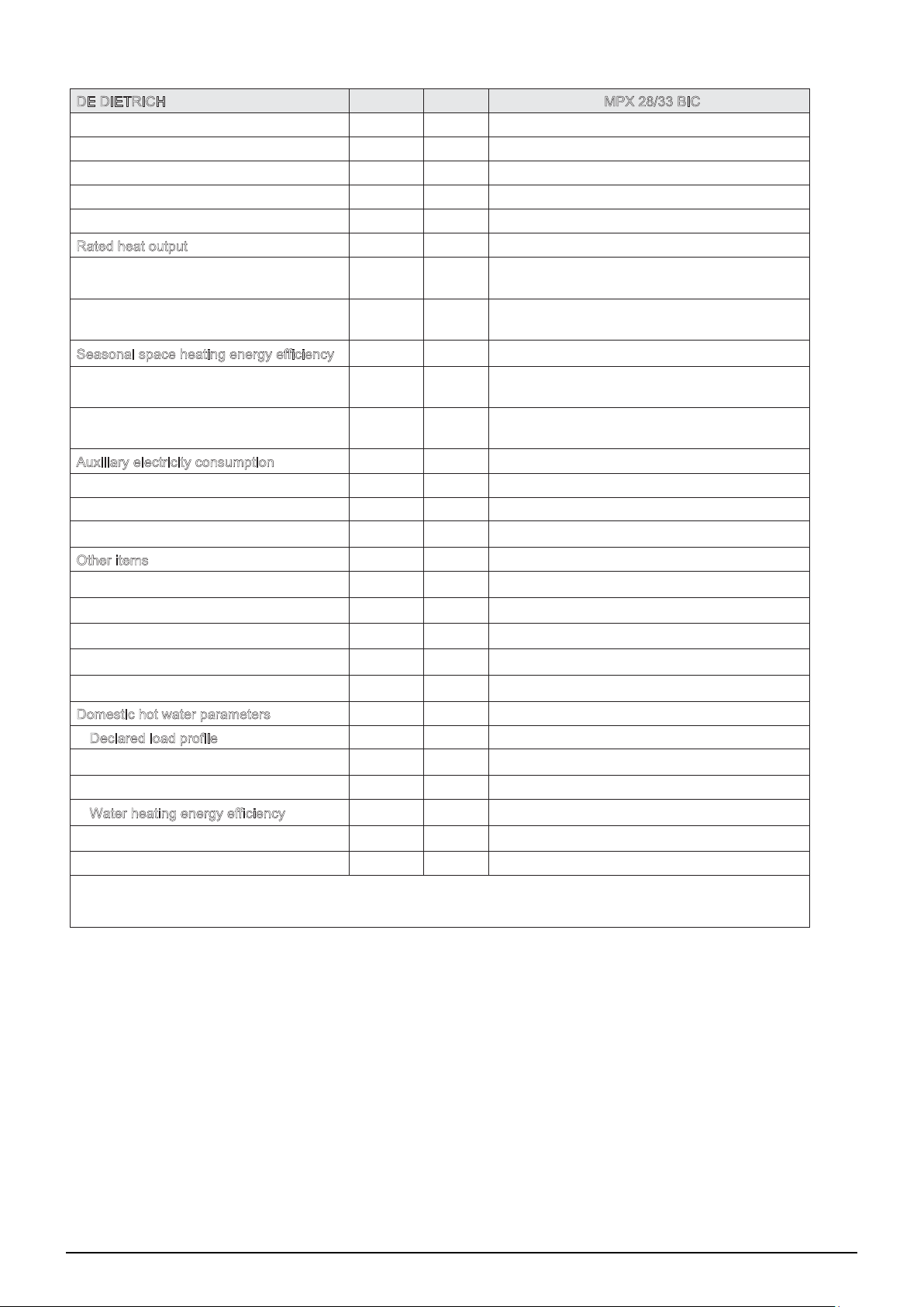
21. TECHNICAL PARAMETERS
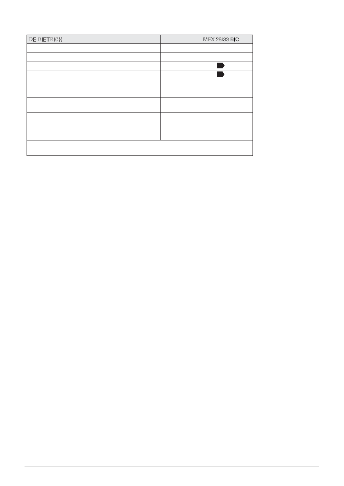
DE DIETRICH
Condensing boiler
(1)
Low-temperature boiler
B1 boiler
Cogeneration space heater
Combination heater
Rated heat output
Useful heat output at rated heat output
and high temperature regime
(2)
Useful heat output at 30% of rated heat
output and low temperature regime
(1)
Prated
P
4
P
1
MPX 28/33 BIC
Yes
No
No
No
Yes
kW 28
kW 28.0
kW 9.4
Seasonal space heating energy efficiency
Useful efficiency at rated heat output and
high temperature regime
(2)
Useful efficiency at 30% of rated heat
output and low temperature regime
(1)
Auxiliary electricity consumption
Full load
Part load
Standby mode
Other items
Standby heat loss
Ignition burner power consumption
Annual energy consumption
Sound power level, indoors
Emissions of nitrogen oxides
Domestic hot water parameters
Declared load profile
Daily electricity consumption
Annual electricity consumption
Water heating energy efficiency
Daily fuel consumption
Annual fuel consumption
(1) Low temperature means for condensing boilers 30°C, for low temperature boilers 37°C and for other heaters 50°C return
temperature (at heater inlet).
(2) High temperature regime means 60°C return temperature at heater inlet and 80°C feed temperature at heater outlet.
ƞ
s
ƞ
4
ƞ
1
elmax
elmin
P
SB
P
stby
P
ign
Q
HE
L
WA
NO
X
Q
elec
AEC
ƞ
wh
Q
fuel
AFC
GJ 18
% 93
% 88.0
% 98.1
kW 0.041
kW 0.013
kW 0.003
kW 0.061
kW 0.000
GJ
87
dB 53
mg/kWh 15
XL
kWh 0.135
kWh 30
% 81
kWh 24.500
INSTALLER Section (en)
21
7679775.01 (1-04/17)
Page 22
22. PRODUCT FICHE
DE DIETRICH
Space heating - Temperature application Medium
Water heating - Declared load profile XL
Seasonal space heating energy efficiency class
Water heating energy efficiency class
Rated heat output
Space heating - Annual energy consumption
Water heating - Annual energy consumption
Seasonal space heating energy efficiency % 93
Water heating energy efficiency % 81
Sound power level L
(1) Electricity
(2) Fuel
(Prated or Psup)
indoors
WA
kW 28
GJ 87
(1)
kWh
30
(2)
GJ
18
dB 53
INSTALLER Section (en)
MPX 28/33 BIC
A
A
7679775.01 (1-04/17) 22
Page 23
Szanowny Kliencie,
nasza rma dokłada wszelkich starań, aby nowy produkt sprostał wszystkim Państwa wymaganiom. Zakup naszego produktu
gwarantuje Państwu zaspokojenie oczekiwań: niezawodne działanie, funkcjonalność i łatwość w użyciu.
Prosimy, żeby nie odkładać na bok niniejszej instrukcji obsługi bez uprzedniego zapoznania się z nią: zawiera ona użyteczne
informacje dla prawidłowego i sprawnego zarządzania zakupionym produktem.
Nasza rma oświadcza, że niniejsze produkty są oznaczone znakiem zgodnie z podstawowymi wymaganiami
następujących Dyrektyw:
- Dyrektywa Gazowa 2009/142/WE
- Dyrektywa o Wydajności 92/42/EWG
- Dyrektywa o Zgodności Elektromagnetycznej 2014/30/WE
- Dyrektywa Niskonapięciowa 2014/35/WE
- Dyrektywa odnośnie projektów eko-kompatybilnych 2009/125/WE
- Dyrektywa o etykietach energetycznych 2010/30/UE
(dla kotłów z P<70kW)
- Rozporządzenie w odniesieniu do ekoprojektu (UE) Nr. 813/2013
- Rozporządzenie o etykietach energetycznych (UE) Nr. 811/2013 (dla kotłów z P<70kW)
Nasza rma, mając na uwadze stałe podnoszenie jakości swoich produktów, zastrzega sobie prawo do modykowania
danych zawartych w niniejszym dokumencie w dowolnym momencie i bez uprzedzenia. Niniejsza dokumentacja ma charakter
informacyjny i w żadnym wypadku nie może być uznana za umowę z osobami trzecimi.
Urządzenie może być obsługiwane przez dzieci w wieku powyżej 8 lat oraz przez
osoby z ograniczonymi zdolnościami zycznymi, sensorycznymi, umysłowymi, bez
doświadczenia lub wymaganej wiedzy, pod warunkiem nadzoru lub po uzyskaniu
odpowiednich instrukcji odnośnie bezpiecznej obsługi urządzenia i zrozumienia zagrożeń z nią związanych. Dzieci nie mogą bawić się urządzeniem. Przegląd oresowy
i czynności z nim związane mogą być wykonywane wyłacznie przez przeszkolone i
autoryzowane my instalacyjne bądź serwisowe.
Użytkownik i instalator (pl)
SPIS TREŚCI
OPIS SYMBOLI .............................................................................................................................................................................................24
INSTRUKCJE DOTYCZĄCE BEZPIECZEŃSTWA .......................................................................................................................................24
OGÓLNE ŚRODKI OSTROŻNOŚCI .............................................................................................................................................................25
WSKAZÓWKI DOTYCZĄCE ODZCZĘDZANIA ENERGII ............................................................................................................................25
1. URUCHOMIENIE KOTŁA .............................................................................................................................................................................26
1.1 NASTAWA TEMPERATURY ZASILANIA C.O. I C.W.U. ...............................................................................................................................26
1.2 TRYBY PRACY .............................................................................................................................................................................................26
2. WYŁĄCZENIE NA DŁUŻSZY OKRES CZASU. OCHRONA PRZECIWZAMARZANIOWA ..........................................................................27
3. PRZEZBROJENIE NA INNY RODZAJ GAZU ...............................................................................................................................................27
4. USTERKI .......................................................................................................................................................................................................27
5. MENU INFORMACYJNE KOTŁA ..................................................................................................................................................................28
6. WYŁĄCZENIE KOTŁA ..................................................................................................................................................................................28
7. NAPEŁNIANIE INSTALACJI .........................................................................................................................................................................28
8. KONSERWACJE OKRESOWE ....................................................................................................................................................................28
INSTRUKCJE PRZED ZAINSTALOWANIEM ...............................................................................................................................................29
9. INSTALOWANIE KOTŁA ...............................................................................................................................................................................29
9.1 DODATKOWE WYPOSAŻENIE DOSTARCZONE W OPAKOWANIU .........................................................................................................29
9.2 WYMIARY KOTŁA .........................................................................................................................................................................................29
10. INSTALOWANIE PRZEWODÓW SPALINOWYCH.......................................................................................................................................30
10.1 PRZEWODY KONCENTRYCZNE ................................................................................................................................................................30
10.2 PRZEWODY ODDZIELNE ............................................................................................................................................................................31
11. PODŁĄCZENIA ELEKTRYCZNE ..................................................................................................................................................................32
11.1 PODŁĄCZENIE TERMOSTATU POKOJOWEGO ........................................................................................................................................32
11.2 WYPOSAŻENIE DODATKOWE NIE OBJĘTE DOSTAWĄ ...........................................................................................................................32
12. FUNKCJE SPECJALNE ................................................................................................................................................................................33
12.1 PIERWSZY ZAPŁON ....................................................................................................................................................................................33
12.2 FUNKCJA ODPOWIETRZENIA INSTALACJI ...............................................................................................................................................33
12.3 KOMINIARZ ..................................................................................................................................................................................................33
12.4 ANALIZA SPALANIA .....................................................................................................................................................................................34
FUNKCJA REGULACJI SPALANIA (CO
13. ZAWÓR GAZOWY ........................................................................................................................................................................................34
13.1 METODY PRZEZBROJENIA NA INNY RODZAJ GAZU ...............................................................................................................................34
14. NASTAWY PARAMETRÓW ..........................................................................................................................................................................35
14.1 REGULACJA MAKSYMALNEJ MOCY OGRZEWANIA ................................................................................................................................36
15. WYSZUKIWANIE USTEREK ........................................................................................................................................................................36
16. URZĄDZENIA REGULACYJNE I ZABEZPIECZAJĄCE ...............................................................................................................................38
17. CHARAKTERYSTYKA NATĘŻENIA PRZEPŁYWU/WYSOKOŚCI CIŚNIENIA ............................................................................................38
18. KONSERWACJA COROCZNA .....................................................................................................................................................................39
18.1 UMIESZCZENIE ELEKTROD .......................................................................................................................................................................39
18.2 WYMIANA CZĘŚCI .......................................................................................................................................................................................39
FUNKCJA AUTOMATYCZNEGO KALIBROWANIA .....................................................................................................................................40
19. DEMONTAŻ, LIKWIDACJA I RECYKLING ...................................................................................................................................................40
20. CHARAKTERYSTYKA TECHNICZNA ..........................................................................................................................................................41
21. DANE TECHNICZNE ....................................................................................................................................................................................42
22. KARTA PRODUKTU ......................................................................................................................................................................................43
%) ................................................................................................................................................34
2
23
7679775.01 (1-04/17)
Page 24
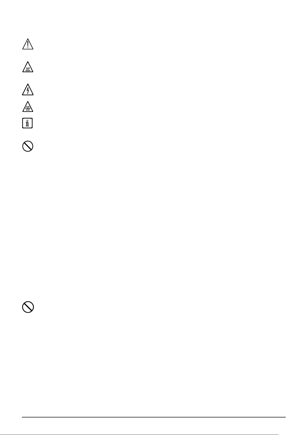
OPIS SYMBOLI
OSTRZEŻENIE
Ryzyko uszkodzenia lub złego funkcjonowania urządzenia. Zwracać szczególną uwagę na ostrzeżenia
odnośnie niebezpieczeństwa dotyczące obrażeń osób.
NIEBEZPIECZEŃSTWO POPARZENIA
Poczekać aż urządzenie ochłodzi się przed przystąpieniem do działania na częściach narażonych na
rozgrzanie.
NIEBEZPIECZEŃSTWO WYSOKIEGO NAPIĘCIA
Części elektryczne pod napięciem, niebezpieczeństwo porażenia prądem elektrycznym.
NIEBEZPIECZEŃSTWO ZAMROŻENIA
Możliwość utworzenia lodu z powodu niskich temperatur.
WAŻNE INFORMACJE
Informacje do przeczytania ze szczególną uwagą ponieważ służą do zapewnienia prawidłowego działania
kotła.
OGÓLNY ZAKAZ
Zakaz wykonywania/używania, w sposób wskazany obok symbolu.
INSTRUKCJE DOTYCZĄCE BEZPIECZEŃSTWA
ZAPACH GAZU
• Wyłączyć kocioł.
• Nie włączać żadnego urządzenia elektrycznego (na przykład światła).
• Zgasić ewentualny wolny płomień i otwórz okna.
• Zgłosić się do autoryzowanego serwisu technicznego.
ZAPACH SPALENIZNY
• Wyłączyć kocioł.
• Wywietrzyć pomieszczenie otwierając drzwi i okna.
• Zgłosić się do autoryzowanego serwisu technicznego.
MATERIAŁ ŁATWOPALNY
Nie używać i nie gromadzić materiałów łatwopalnych (rozpuszczalniki, papier, itp) w pobliżu kotła.
KONSERWACJA I CZYSZCZENIE KOTŁA
Wyłączyć zasilanie elektryczne w kotle przed przystąpieniem do wykonywania wszelkich interwencji.
Urządzenie nie może być używane przez osoby, które mają ograniczone zdolności zyczne, sensoryczne lub umysłowe oraz
przez osoby nie mające doświadczenia ani nie znają urządzenia, chyba, że są one nadzorowane i poinstruowane odnośnie
obsługi urządzenia przez osoby odpowiedzialne za ich bezpieczeństwo.
Użytkownik i instalator (pl)
7679775.01 (1-04/17) 24
Page 25
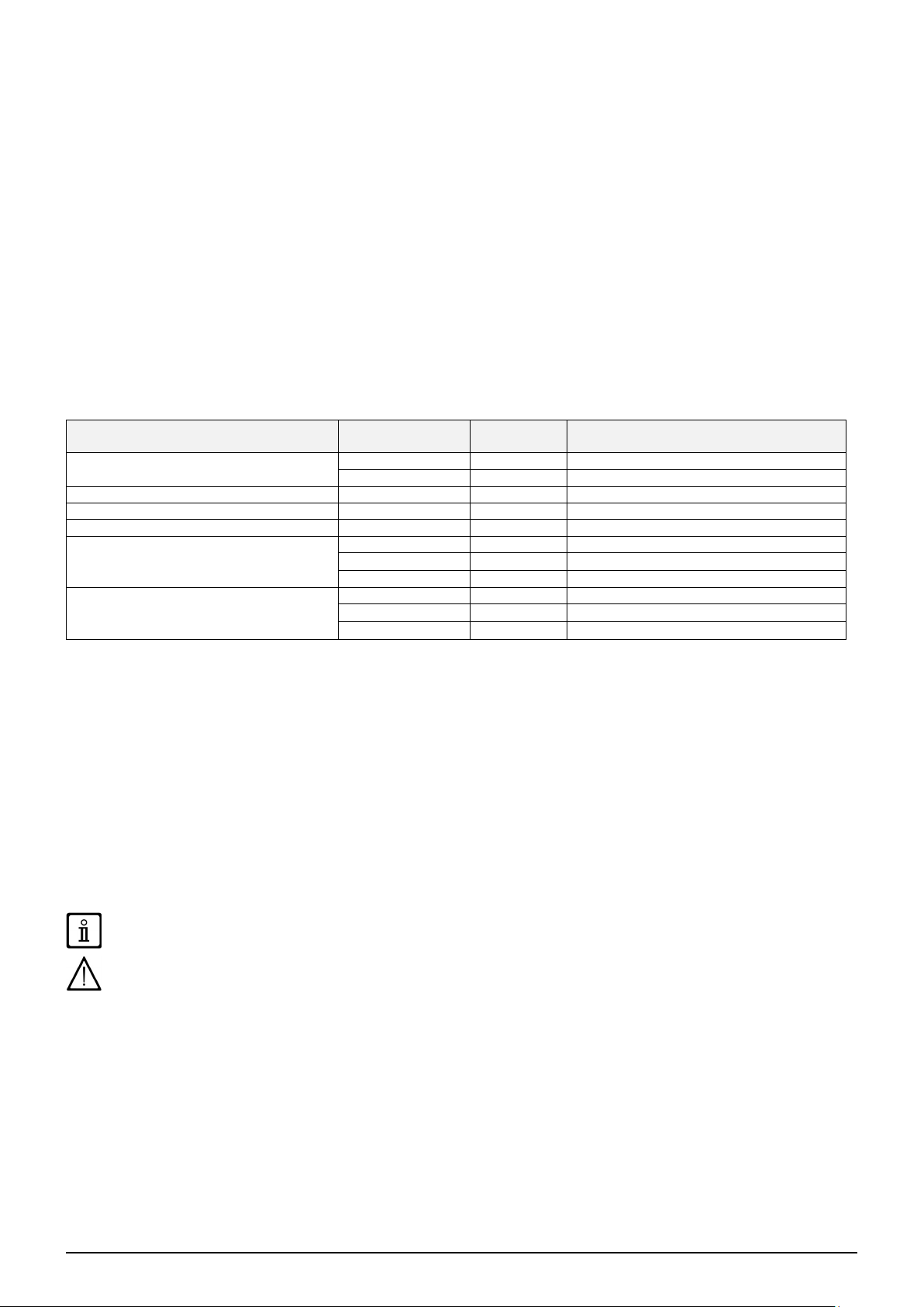
OGÓLNE ŚRODKI OSTROŻNOŚCI
Niniejszy kocioł został zaprojektowany do podgrzewania wody grzewczej do temperatury niższej od temperatury wrzenia pod
ciśnieniem atmosferycznym. Kocioł należy podłączyć do instalacji centralnego ogrzewania i c.w.u. odpowiednio do jego sprawności
i mocy. Przed zaintalowaniem kotła przez uprawnionego instalatora należy wykonać następujące czynności:
• Upewnić się, że kocioł jest nastawiony do pracy z dostarczanym rodzajem gazu. W tym celu sprawdzić oznaczenia na opakowaniu i tabliczce znamionowej urządzenia.
• Upewnić się, że ciąg kominowy jest odpowiedni, wylot spalin nie jest zatkany i że przez ten sam przewód spalinowy nie są
odprowadzane spaliny z innych urządzeń, o ile nie jest on specjalnie zaprojektowany do odprowadzania spalin z więcej niż
jednego urządzenia, zgodnie z obowiązującym prawem.
• Upewnić się, że kocioł jest podłączony do istniejących przewodów spalinowych, starannie oczyszczonych z resztek produktów
spalania, które w trakcie pracy mogą oderwać się od ścianek i utrudnić przepływ spalin.
• Dla zapewnienia prawidłowej pracy i zachowania gwarancji należy przestrzegać następujących środków ostrożności.
1. Obieg c.w.u.
1.1 Jeżeli twardość wody jest wyższa od 20 °F (1 °F = 10 mg węglanu wapnia na litr wody), zainstalować system uzdatniania,
zgodny z aktualnymi przepisami.
1.2 Starannie przepłukać instalację po zainstalowaniu urządzenia i przed użyciem.
1.3 Materiały zastosowane w obiegu c.w.u. muszą być zgodne z dyrektywą 98/83/EC.
2. Obieg grzewczy
Instalację grzewczą napełnić świeżą wodą (wartość pH powinna mieścić się między 7 a 9. Aby zapobiec problemom z kotłem
lub instalacją, przestrzegać danych w poniższej tabeli. Jeżeli jeden lub więcej warunków nie mogą być spełnione, zaleca się
uzdatnienie wody
2.1 Warunki wstępne: Uzdatniać wodę w instalacji, aby ograniczyć korozję, gromadzenie się kamienia kotłowego, zanieczyszczenia,
skażenie mikrobiologiczne. Dla optymalnej pracy kotła, woda w instalacji powinna posiadać następujące parametry.
Moc ≤ 70 kW Moc >70 kW
lub w instalacji pracującej w stałej temperaturze
Zawartość kwasu (pH)
Przewodność do 25 °C µS/cm ≤ 800 ≤ 800
Chlorki mg/l ≤ 150 ≤ 150
Inne substancje mg/l < 1 < 1
Twardość wody w instalacji przy pojemności
wodnej <6 l/kW
Twardość wody w instalacji przy pojemności
wodnej >6 l/kW
Twardość wody we Francji to °f, w Niemczech dH. Jeden stopień °f odpowiada mg/l karbidu, Jeden stopień w niemieckich jednostkach odpowiada
1,79°f.
woda nie uzdatniona 7 - 9 7 - 9
woda uzdatniona 7 - 8,5 7 - 8,5
°f 1 - 20 1 - 5
°dH 0,5 - 11,2 0,5 - 2,8
mmol/l 0,1 - 2 0,1 - 0,5
°f 1 - 15 1 – 5
°dH 0,5 - 8,4 0,5 - 2,8
mmol/l 0,1 - 1,5 0,1 - 0,5
2.2 Ważne ogólne wskazówki odnośnie jakości wody: Kotły grzewcze DE DIETRICH dopuszczone są do pracy z czystą
wodą wodociągową o dobrej jakości. Większość systemów grzewczych wykonana jest z różnych materiałów. Z tego względu
zaleca się stosowanie wody uzdatnionej aby uniknąć lub ograniczyć problemy (korozja metali, osadzanie się kamienia kotłowego,
zmiany chemiczne w nieuzdatnionej wodzie). W obiegach grzewczych możliwie maksymalnie redukować ilość tlenu w wodzie.
Maksymalne roczne uzupełnianie wody to 5%. Zaleca się montaż ltrów na powrocie z instalacji c.o oraz dolocie zimnej wody.
Pełne wyczyszczenie instalacji musi być wykonane przez autoryzowanego instalatora. Aby z obiegu grzewczego usunąć wszystkie
zanieczyszczenia i osady, wymagany jest dostateczny i wyregulowany przepływ wody. Do uzdatniania wody oraz czyszczenia
instalacji zaleca się stosowanie środków chemicznych rm SENTINEL, SOTIN oraz REPA. W razie znacznego zanieczyszczenia
kotła (złogi kamienia kotłowego), czyszczenie musi być wykonane przez autoryzowanego instalatora odpowiednimi narzędziami.
2.3 Nowe instalacje: Nową instalację oczyścić z wszelkich pozostałości tj (resztek z tworzyw sztucznych, części montażowych,
środków smarujących itd). Czyszczenie środkami chemicznymi musi być wykonywane przez autoryzowanego instalatora.
Nie zmiękczać wody do wartości mniejszej niż 0.5 dH (1°f), zbyt miękka woda uszkadza instalację. W połączeniu ze środkami
zmiękczającymi muszą być stosowane inhibitory.
2.4 Obieg grzewczy: Przed zainstalowaniem kotła opróżnić instalację i oczyścić ją, aby usunąć szlam i zanieczyszczenia,
używając przy tym odpowiednich produktów. Zaleca się następujące środki czyszczące: SENTINEL X300 lub X400 dla obiegów
grzewczych. Przy używaniu tych produktów przestrzegać ściśle instrukcji producentów. Należy pamiętać, że obecność obcych ciał
w instalacji grzewczej może wpłynąć niekorzystnie na pracę kotła (np. przegrzanie, lub nadmierny hałas wymiennika).
Brak przestrzegania tych zaleceń powoduje unieważnienie gwarancji urządzenia. Przed rozruchem usunąć folię ochronną z
kotła. Nie wolno używać do tego celu narzędzi ani materiałów ściernych, ponieważ mogą one uszkodzić polakierowane
części.
Części opakowania (woreczki plastikowe, polistyrenowe itp.) nie wolno zostawiać w zasięgu dzieci, ponieważ stanowią one
źródło zagrożenia.
WSKAZÓWKI DOTYCZĄCE ODZCZĘDZANIA ENERGII
Regulacja w trybie ogrzewania
Nastawić temperaturę zasilania kotła zależnie od rodzaju instalacji. W instalacjach grzejnikowych ustawić maksymalną
temperaturę zasilania na ok.60°C, i zwiększyć tę wartość jeżeli żądana temperatura pomieszczenia nie została osiągnięta.
Wykorzystać czujnik zewnętrzny i/lub konsolę sterowniczą do automatycznej nastawy temperatury zasilania zależnie od
warunków atmosferycznych lub temperatury w pomieszczeniu. Zapewnia to wytwarzanie tylko rzeczywiście wymaganej ilości
ciepła. Nastawić temperaturę pokojową bez przegrzewania pomieszczeń. Każdy dodatkowy stopień Celsjusza oznacza większe
zużycie energii o ok. 6%. Temperatura w pomieszczeniu zależy również od sposobu jego wykorzystania. Na przykład, sypialnia
i rzadko używane pomieszczenia mogą być ogrzewane do niższej temperatury. Użyć programowalny zegar sterujący i nastawić
temperaturę pomieszczenia w nocy o ok. 5°C niższą niż w ciągu dnia. Ustawienie jej jeszcze niżej nie przynosi znacznych
oszczędności. Tylko w przypadku dłuższej nieobecności, np, w czasie urlopu, wartość zadana temperatury powinna być obniżona.
Nie zakrywać grzejników, ponieważ uniemożliwia to prawidłowy obieg powietrza. Nie pozostawiać uchylonych częściowo okien
dla wentylacji pomieszczeń, lecz otwierać je całkowicie na krótki okres czasu.
Ciepła woda użytkowa
Duże oszczędności daje nastawa c.w.u. o żądanej temperaturze bez mieszania jej z zimną wodą. Dodatkowe grzanie marnuje
energię i sprzyja tworzeniu się dodatkowych osadów kamienia kotłowego.
Użytkownik i instalator (pl)
25
7679775.01 (1-04/17)
Page 26
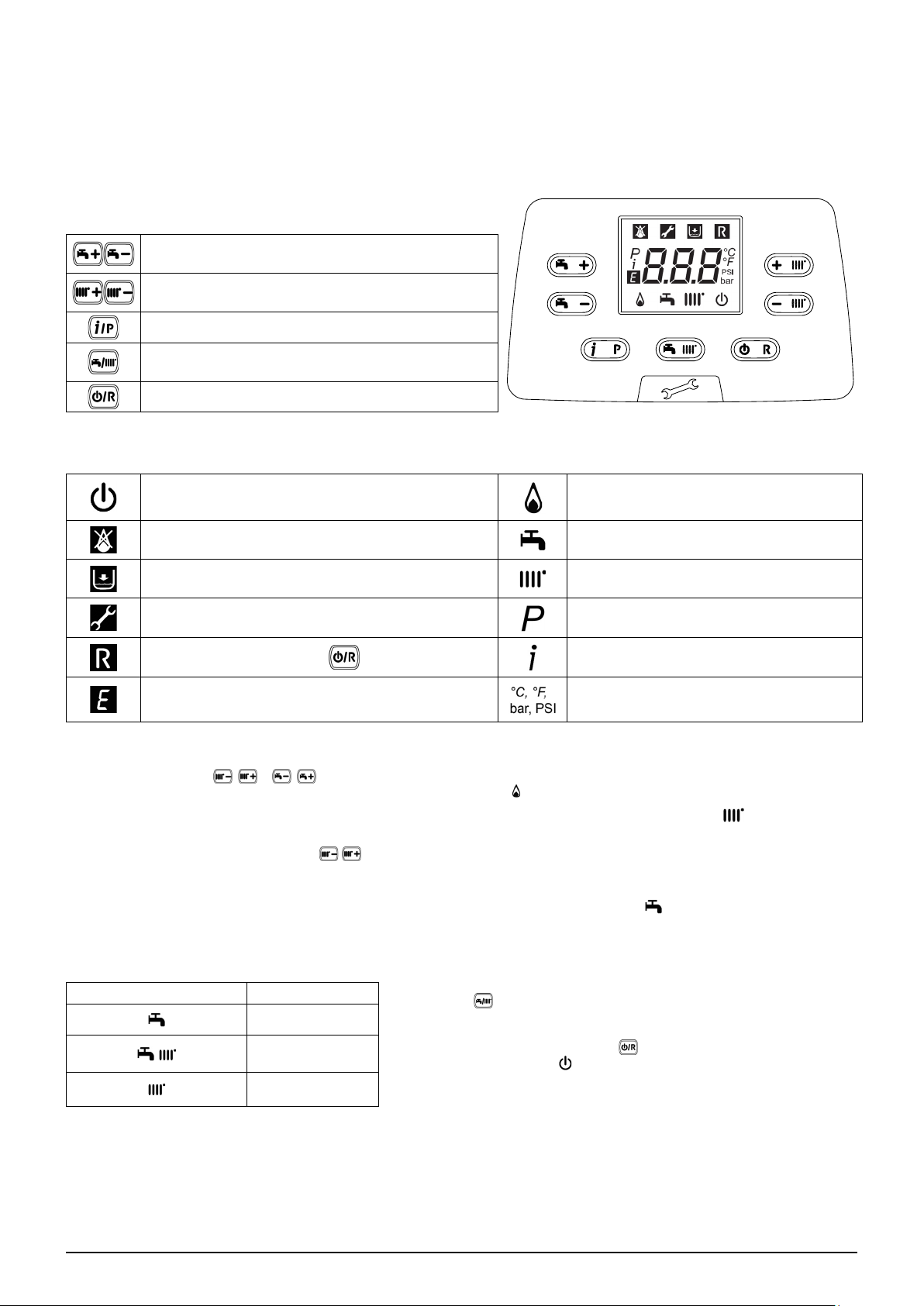
1. URUCHOMIENIE KOTŁA
Dla prawidłowego załączenia kotła postępować następująco:
• Sprawdzić, czy ciśnienie w instalacji jest prawidłowe (rozdz. 7);
• Włączyć zasilanie elektryczne kotła;
• Otworzyć zawór gazowy (żółty, umieszczony pod kotłem);
• Wybrać żądany tryb ogrzewania (rozdz. 1.2).
PRZYCISKI
Nastawa temperatury c.w.u.
(+ aby zwiększyć temperaturę i – aby ją zmniejszyć)
Nastawa temperatury wody grzewczej
(+aby zwiększyć temperaturę i – aby ją zmniejszyć)
Informacja o pracy kotła
Tryb pracy:
c.w.u. – c.w.u. i c.o. – tylko c.o.
Wył – Reset – wyjście z menu/funkcji
SYMBOLE
Wył: ogrzewanie I c.w.u. wyłączone
(aktywna tylko ochrona przeciwzamarzaniowa kotła)
Usterka uniemożliwiająca zapalenie palnika Tryb c.w.u. dozwolony
Niskie ciśnienie wody w kotle/instalacji Tryb c.o. dozwolony
Wezwanie autoryzowanego serwisu Menu programowania
Usterka ręcznie resetowana ( )
Usterka trwa Jednostki miary (SI/US)
Palnik zapalony
Menu informacji o kotle
1.1 NASTAWA TEMPERATURY ZASILANIA C.O. I C.W.U.
Nacisnąć odpowiednio i , aby nastawić temperaturę zasilania c.o. i c.w.u. (jeżeli jest podłączony zewnętrzny
zasobnik). Gdy palnik jest zapalony, na ekranie wyświetlany jest symbol .
OGRZEWANIE: podczas pracy kotła w trybie ogrzewania na ekranie wyświetlany jest migająco symbol oraz temperatura
zasilania (°C).
Gdy podłączony jest czujnik zewnętrzny, pośrednio regulują temperaturę pomieszczenia (nastawa fabryczna 20°C – zob.
rozdział 11.2.1).
C.W.U.: Podczas pracy kotła w trybie c.w.u., na ekranie wyświetlany jest migająco symbol oraz temperatura pierwotnego
obiegu kotłowego (°C).
Sekcja UŻYTKOWNIKA (pl)
1.2 TRYBY PRACY
WYŚWIETLANY SYMBOL TRYB PRACY
C.W.U.
C.W.U. I C.O.
TYLKO C.O.
Aby umożliwić pracę kotła w trybie c.w.u. - c.o. lub tylko c.o. nacisnąć
kilkakrotnie
Aby wyłączyć tryby pracy kotła zachowując funkcję ochrony
przeciwzamarza-niowej, naciskać
ekranie pojawi się symbol
ekranu miga).
i wybrać jeden z trzech dostępnych trybów.
przez minimum 3 sekundy. Na
(jeżeli kocioł jest zablokowany, podświetlenie
7679775.01 (1-04/17) 26
Page 27
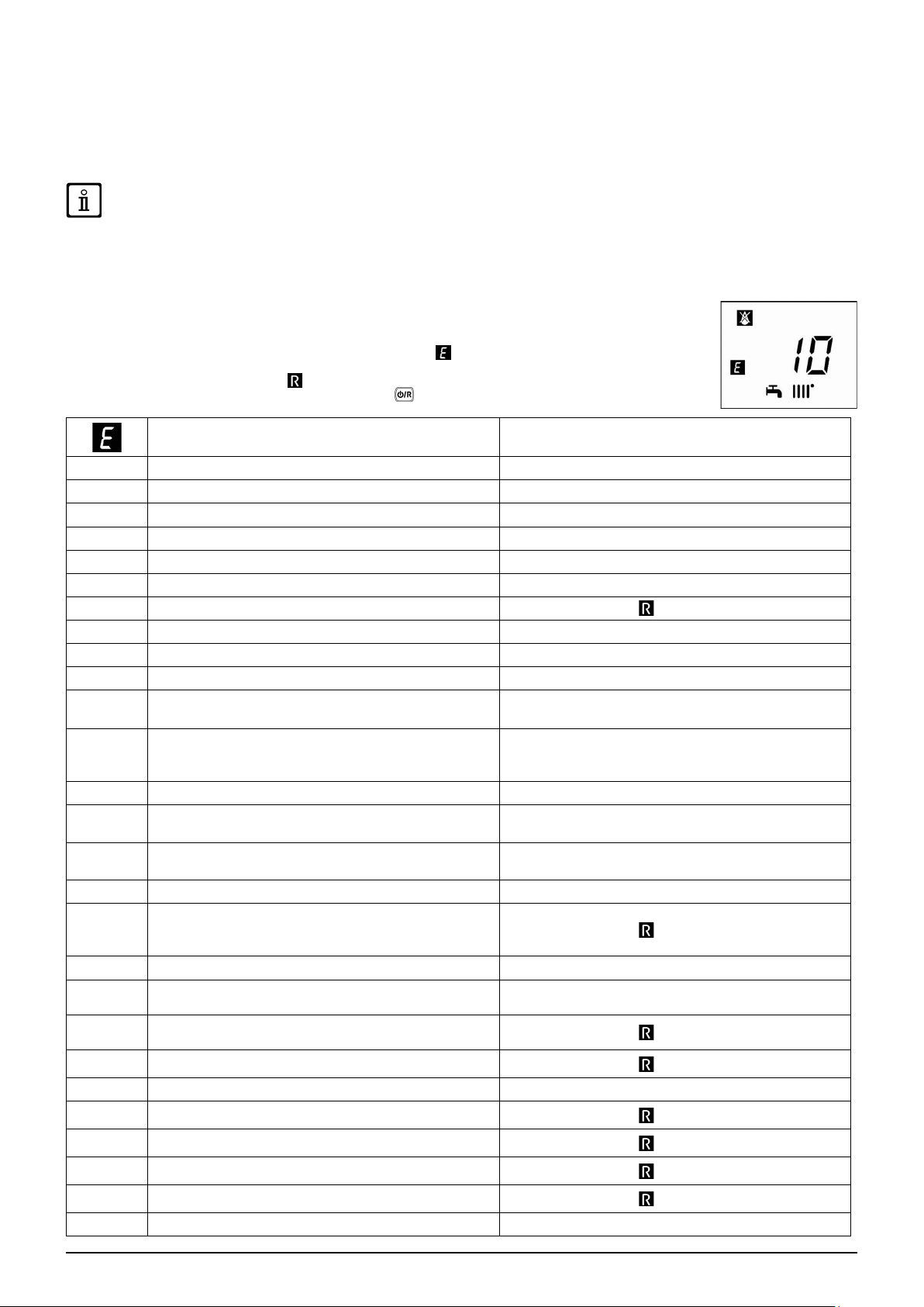
2. WYŁĄCZENIE NA DŁUŻSZY OKRES CZASU. OCHRONA
PRZECIWZAMARZANIOWA
Nie opróżniać całej instalacji, ponieważ ponowne napełnienie wodą powoduje niepotrzebne i szkodliwe osadzanie się kamienia
kotłowego wewnątrz kotła i elementach grzejnych. Jeżeli w trakcie zimy kocioł nie jest używany i w związku z tym jest narażony
na zamarznięcie, dodać do wody w instalacji środek przeciwzamarzaniowy (np. propylenoglikol w połączeniu z inhibitorami korozji
i kamienia kotłowego). Sterowanie elektroniczne kotła zawiera funkcję “ochrona przed zamarznięciem” instalacji c.o., która w
momencie spadku temperatury zasilania poniżej 5°C, uruchamia palnik, aż do osiągnięcia temperatury 30°C.
Funkcja jest dostępna jeżeli: kocioł jest podłączony do zasilania elektrycznego, dostarczany jest gaz, ciśnienie w instalacji
jest normalne i kocioł nie jest zablokowany.
3. PRZEZBROJENIE NA INNY RODZAJ GAZU
Kotły mogą pracować zarówno z gazem ziemnym (G20-G27), jak i z LPG (G31). Wszelkie przezbrojenia na inny rodzaj gazu
muszą być wykonywane przez AUTORYZOWANY SERWIS.
4. USTERKI
Usterki są przedstawiane na ekranie przy pomocy symbolu i numeru (kod usterki). Kompletny wykaz
usterek zawiera tabela poniżej.
Jeżeli na ekranie pojawi się symbol usterka może być RESETOWANA przez użytkownika.
Dla ZRESETOWANIA kotła naciskać przez 2 sekundy . Jeżeli usterka jest wyświetlana często, wezwać
autoryzowany serwis.
Opis usterki Działanie
09
10
12
13
15
18
19
20
28
40
50
Błąd podłączenia zaworu gazowego Wezwać autoryzowany serwis.
Usterka czujnika zewnętrznego Wezwać autoryzowany serwis.
Usterka przełączenia presostatu różnicowego wody Wezwać autoryzowany serwis.
Zablokowane zestyki presostatu różnicowego wody Wezwać autoryzowany serwis.
Usterka zaworu gazowego Wezwać autoryzowany serwis.
Automatyczne napełnianie obiegu hydraulicznego w toku Poczekać do zakończenia cyklu napełniania
Usterka w fazie napełniania układu
Usterka czujnika zasilania NTC Wezwać autoryzowany serwis.
Usterka czujnika spalin NTC Wezwać autoryzowany serwis.
Usterka czujnika powrotu NTC Wezwać autoryzowany serwis.
Usterka czujnika c.w.u. NTC (jedynie model tylko do c.o.
z podgrzewaczem pojemnościowym)
Nacisnąć i przytrzymać
Wezwać autoryzowany serwis.
przez co najmniej 2 sekundy.
Sekcja UŻYTKOWNIKA (pl)
53
55
83…87
92
109
110
117
118
125
128
129
130
133
134
135
154
Zablokowany wylot spalin
Nie skalibrowana płyta elektroniczna Wezwać autoryzowany serwis.
Problem komunikacji między płytą kotła i sterowaniem.
Prawdopodobnie zwarcie w przewodach.
Usterka spalin w trakcie kalibrowania (prawdopodobnie
recyrkulacja spalin)
Powietrze w obiegu kotłowym (usterka tymczasowa) Wezwać autoryzowany serwis.
Zadziałał termostat zabezp. z powodu nadmiernej temp.
(prawdopod. zablokowana pompa lub zapowietrzony obieg
c.o.)
Za wysokie ciśnienie w obiegu hydraulicznym (> 2,7 bar) Wezwać autoryzowany serwis.
Za niskie ciśnienie w obiegu hydraulicznym
Brak wyzwolenia zabezpieczającego cyrkulacji
(sterowanie poprzez czujnik temperatury)
Brak płomienia
Utrata płomienia przy zapłonie Chiamare il centro assistenza tecnica autorizzato
Zadziałał czujnik NTC spalin z powodu nadmiernej temp.
Usterka zapłonu (5 prób)
Zablokowany zawór gazowy
Wewnętrzna usterka płyty
Test kontrolny czujnika zasilania/powrotu Wezwać autoryzowany serwis.
Odłączyć kocioł od zasilania elektrycznego na parę sekund.
Jeżeli usterka nie ustąpiła, wezwać autoryzowany serwis
Wezwać autoryzowany serwis.
Wezwać autoryzowany serwis.
Nacisnąć i przytrzymać
Sprawdzić, czy ciśnienie w instalacji jest prawidłowe; Patrz
rozdział NAPEŁNIANIE INSTALACJI..
Nacisnąć i przytrzymać
Nacisnąć i przytrzymać
Nacisnąć i przytrzymać
Nacisnąć i przytrzymać
Nacisnąć i przytrzymać
Nacisnąć i przytrzymać
przez co najmniej 2 sekundy.
przez co najmniej 2 sekundy.
przez co najmniej 2 sekundy.
przez co najmniej 2 sekundy.
przez co najmniej 2 sekundy.
przez co najmniej 2 sekundy.
przez co najmniej 2 sekundy.
27
7679775.01 (1-04/17)
Page 28
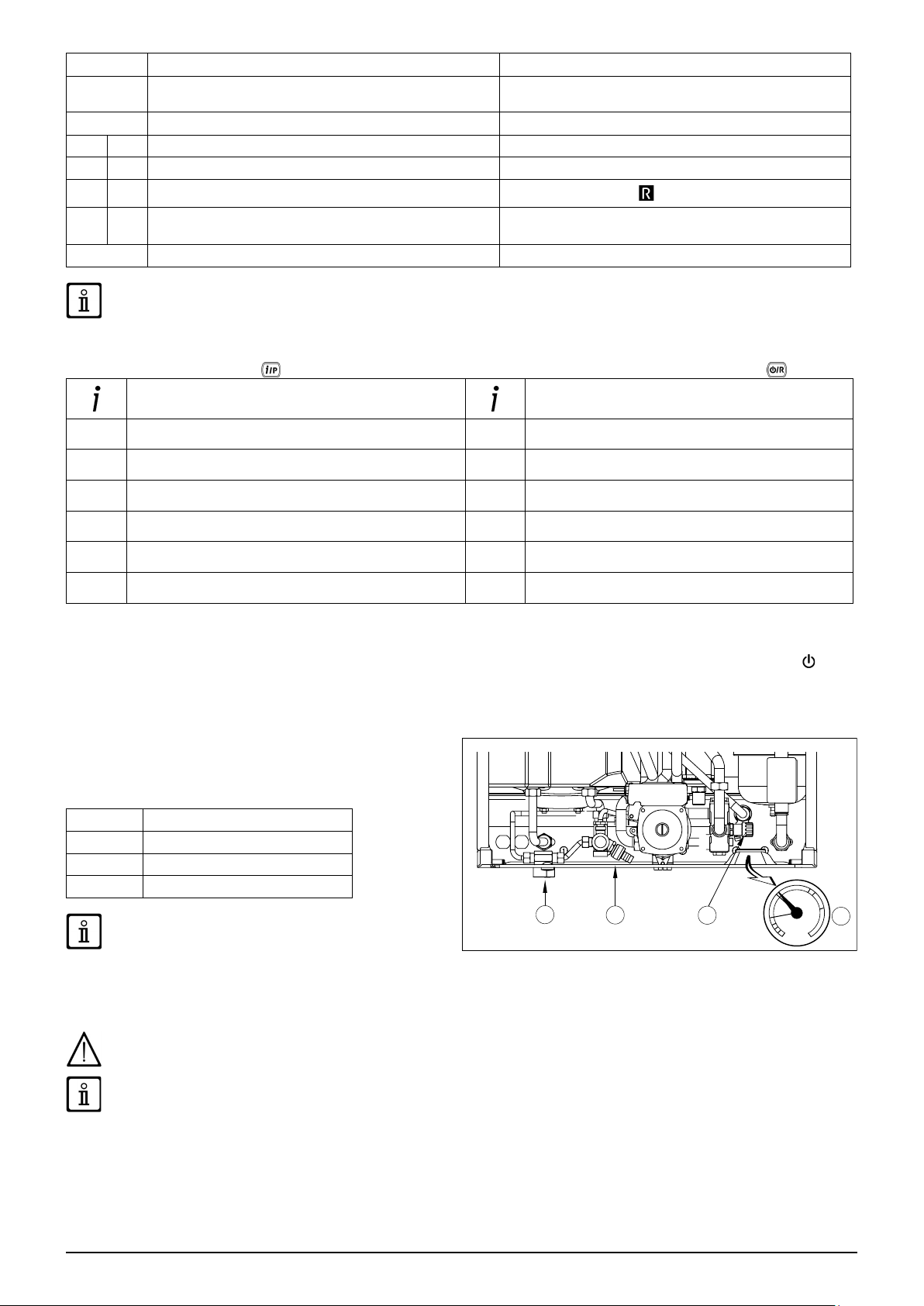
160
178
270
317 162
321 163
384 164
385 165
431
Usterka wentylatora Wezwać autoryzowany serwis.
Zadziałanie termostatu zabezpieczającego przy nadmiernej
temperaturze w instalacji niskotemperaturowej
Przegrzanie wymiennika Wezwać autoryzowany serwis.
Nieprawidłowa częstotliwość zasilania elektrycznego Wezwać autoryzowany serwis.
Usterka czujnika c.w.u. NTC Wezwać autoryzowany serwis.
Fałszywy płomień (usterka wewnętrzna)
Za niskie napięcie wejściowe
Czujnik wymiennika uszkodzony Wezwać autoryzowany serwis.
W przypadku wystąpienia usterki podświetlenie ekranu wskazuje kod usterki. Można wykonać 5 prób resetu, po których
kocioł się wyłącza. Przed ponowną próbą resetu kotła poczekać 15 minut.
Wezwać autoryzowany serwis.
Nacisnąć i przytrzymać
Automatyczny reset przy napięciu poniżej 175V. Jeżeli
usterka nie ustąpiła, wezwać autoryzowany serwis.
przez co najmniej 2 sekundy.
5. MENU INFORMACYJNE KOTŁA
Przytrzymać wciśnięty przycisk przez min. 1 sekundę, aby wyświetlić informację wskazaną w tabeli. Nacisnąć aby wyjść.
OPIS OPIS
00
01
02
03
04
05
Kod wewnętrzny usterki wtórnej
Temperatura zasilania c.o. (°C)
Temperatura zewnętrzna (°C)
Temp. c.w.u. zasobnika pośredn. (kocioł tylko do co)
Temperatura c.w.u. (kocioł z wymiennikiem płytowym)
Ciśnienie wody instalacji grzewczej (bar)
06
07
08
09 - 13
14
15 - 18
Temperatura powrotu z c.o. (°C)
Temperatura czujnika spalin (°C)
Temperatura wymiennika pierwotnego (°C)
Informacje producenta
Identykacja komunikacji Open Therm
Informacje producenta
6. WYŁĄCZENIE KOTŁA
Aby wyłączyć kocioł, należyodłączyć go od zasilania elektrycznego wyłącznikiem dwubiegunowym. W trybie „Wył” kocioł
pozostaje wyłączony lecz obwody elektryczne pozostają pod napięciem i aktywna jest ochrona przeciwzamarzaniowa.
7. NAPEŁNIANIE INSTALACJI
Regularnie sprawdzać, czy wartość ciśnienia wyświetlana na
ciśnieniomierzu "D" wynosi 1 - 1,5 bar, przy zimnym kotle.
Jeżeli ciśnienie jest za niskie, obrócić zawór "A", aby napełnić
kocioł (rys. obok).
A Kurek załadowczy kotła
B Kurek spustowy bojlera
C Kurek spustowy kotła
D Manometr
Zaleca się zachowanie szczególnej ostrożności w fazie
Sekcja UŻYTKOWNIKA (pl)
instalacji, przepuścić powoli wodę w celu uniknięcia powstania
powietrza wewnątrz pierwotnego obwodu dopóki nie osiągnie się ciśnienia koniecznego do działania. Na koniec odpowietrzyć
ewentualne elementy grzejne instalacji. De Dietrich nie bierze na siebie żadnej odpowiedzialności za szkody spowodowane
obecnością pęcherzyków powietrza wewnątrz wymiennika ciepła z powodu nieprawidłowego lub braku zastosowania się do
powyższych wskazówek.
napełniania instalacji grzewczej. Przede wszystkim
otworzyć zawory termostatyczne, gdy są obecne w
Kocioł jest wyposażony w czujnik ciśnienia wody, który uniemożliwia pracę kotła w przypadku braku wody.
W razie częstego występowania spadku ciśnienia, kocioł powinien być sprawdzony przez autoryzowany serwis.
8. KONSERWACJE OKRESOWE
Aby utrzymać kocioł sprawny i bezpieczny, musi on być sprawdzony przez autoryzowany serwis pod koniec każdego sezonu
grzewczego.
Skrupulatny przegląd zapewnia oszczędną pracę instalacji
7679775.01 (1-04/17) 28
Page 29
INSTRUKCJE PRZED ZAINSTALOWANIEM
Poniższe uwagi i instrukcje są adresowane do instalatorów, aby umożliwić im bezproblemowe wykonanie instalacji. Instrukcje
dotyczące załączenia i eksploatacji zawarto w części “Instrukcje dla użytkownika”. Instalowanie, konserwacja oraz uruchomienie
domowych instalacji opalanych gazem musi być przeprowadzone przez uprawnionych instalatorów, zgodnie z obowiązującymi
przepisami.
Ponadto należy pamiętać:
• W przypadku montowania urządzenia w miejscu o temperaturze otoczenia poniżej 0°C, należy przedsięwziąć odpowiednie
środki ostrożności w celu niedopuszczenia do tworzenia się lodu w syfonie i przy wylocie kondensatu.
• Ten kocioł można podłączyć do każdego typu dwu- lub jednoprzewodowego konwektora, grzejnika lub termokonwektora.
Projektować przekroje instalacji jak zwykle, jednakże uwzględniając możliwy przepływ-wysokość tłoczenia w płycie (jak
przedstawiono w rozdz. E).
• Pierwsze uruchomienie kotła musi być wykonane przez autoryzowanego instalatora, wskazanego na załączonej ulotce.
Nieprzestrzeganie powyższego spowoduje anulowanie i utratę gwarancji.
Części opakowania (woreczki plastikowe, polistyrenowe itp.) nie wolno zostawiać w zasięgu dzieci, ponieważ stanowią one
źródło zagrożenia.
9. INSTALOWANIE KOTŁA
Rysunek wzornika jest dostępny na końcu instrukcji obsługi w załączniku "SECTION" C.
Po podjęciu decyzji o dokładnej lokalizacji kotła, przymocować szablon do ściany. Podłączyć instalację do wlotów gazu i wody
znajdujących się na dolnym pasie szablonu. Upewnić się, że tył kotła jest równoległy do ściany (w przeciwnym razie regulować za
pomocą podkładek dolną część). Zamontować dwa zawory G 3/4 (zasilanie i powrót) w obiegu c.o.; dzięki tym zaworom można
wykonać ważne prace w instalacji bez całkowitego jej opróżniania. Jeżeli instaluje się kocioł w istniejącej instalacji lub wymienia
się go, jak również jak powyżej, zamontować zbiornik osadowy pod kotłem w przewodzie powrotnym w celu zebrania wszelkich
osadów i kamienia kotłowego krążących w instalacji po przepłukaniu. Po zamocowaniu kotła na szablonie podłączyć przewody
spalinowe i powietrzne, dostarczane jako wyposażenie dodatkowe, jak opisano w dalszych rozdziałach. Podłączyć syfon ze
stałym spadkiem. Unikać poziomych odcinków.
Sekcja INSTALATORA (pl)
Nie podnosić urządzenia chwytając za plastikowe komponenty, takie jak na przykład syfon czy wieżyczka dymu.
Docisnąć łączniki wodne kotła z zachowaniem ostrożności (maksymalny moment dokręcania = 30 Nm).
Przed włączeniem kotła, napełnić syfon wodą w celu niedopuszczenia, do niekontrolowanego wypływu spalin.
9.1 DODATKOWE WYPOSAŻENIE DOSTARCZONE W OPAKOWANIU
• Wzornik (patrz rysunek w załączniku "SECTION" C)
• Poprzecznica wsporcza kotła
• Kołki rozporowe 8 mm i śruby dociskowe
• Przewód odprowadzający skropliny
AKCESORIA dostarczone na życzenie:
• Kurki zasilania/powrotu c.o., kurek wlotu wody i łączniki teleskopowe
• Kurek gazowy
9.2 WYMIARY KOTŁA
Wymiary kotła i właściwe wysokości instalacyjne złączy wodnych są podane na końcu instrukcji w załączniku "SECTION" C.
29
7679775.01 (1-04/17)
Page 30
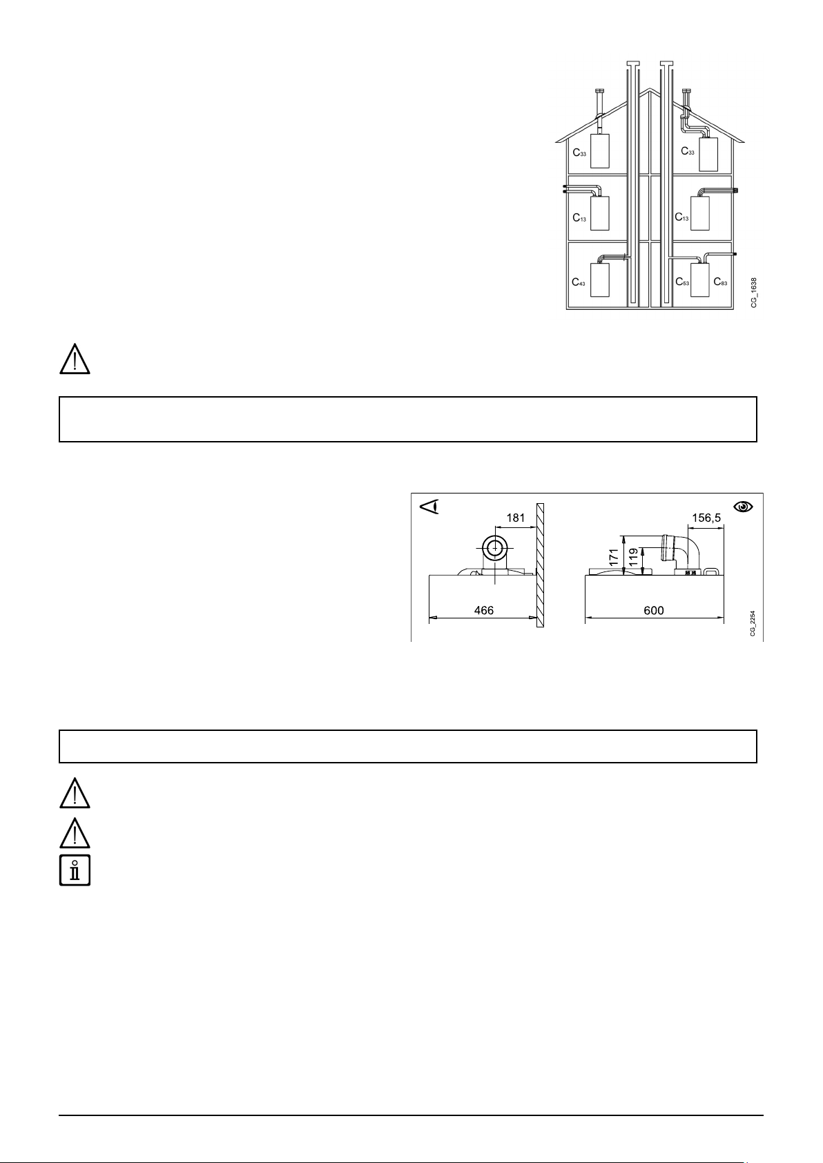
10. INSTALOWANIE PRZEWODÓW SPALINOWYCH
Kocioł jest łatwy do zainstalowania dzięki szerokiemu asortymentowi dostępnych
akcesoriów, jak opisano poniżej. Kocioł został zaprojektowany do podłączenia do
pionowego lub poziomego koncentrycznego przewodu powietrzno-spalinowego. Kocioł
może być używany również z oddzielnymi przewodami z wykorzystaniem zestawu
rozdzielającego.
OSTRZEŻENIA
C13, C33 Wyloty oddzielnych przewodów należy zamontować wewnątrz kwadratu 50
cm. Szczegółowe instrukcje dostarcza się z poszczególnymi akcesoriami.
C53 Nie montować wylotów przewodów powietrznych i spalinowych na przeciwległych
ścianach budynku.
C63 Spadek ciśnienia w przewodach nie może przekraczać 100 Pa. Przewody muszą
posiadać atest dla tego konkretnego zastosowania oraz dla temperatury przekraczającej 100°C. Wylot przewodu spalinowego musi mieć atest wg EN 1856-1.
C43, C83 Wylot przewodu spalinowego lub przewód spalinowy musi być odpowiedni
dla tego celu.
W celu zagwarantowania maksymalnego bezpieczeństwa podczas działania, konieczne jest, aby przewody wylotowe spalin były
odpowiednio przymocowane do ściany za pomocą specjalnych wsporników mocujących. Wsporniki muszą być umieszczone w
odległości około 1 metra jeden od drugiego w pobliżu łączników.
Przeczytać uważnie instrukcje przewodów zawartych w niniejszym podręczniku oraz instrukcje dostarczone razem
z dodatkowym wyposażeniem, w przypadku różnic, instrukcje przewodów niniejszego podręcznika muszą być
przestrzegane.
10.1 PRZEWODY KONCENTRYCZNE
Ten rodzaj przewodu jest używany do odprowadzenia spalin
i doprowadzenia powietrza do spalania z zewnątrz budynku i
gdy zamontowany jest kanał spalinowy LAS. Koncentryczne
kolano 90° umożliwia podłączenie kotła do przewodu
powietrzno-spalinowego w dowolnym kierunku, ponieważ
można je obracać o 360°. Można je również zastosować jako
kolano dodatkowe w połączeniu z przewodem koncentrycznym
lub kolanem 45°.
W przypadku odprowadzania spalin na zewnątrz, przewód
wylotowo-zasysający musi wystawać ze ściany na długość co
najmniej 18 mm, aby umożliwić nałożenie aluminiowej rozety i
jej zaplombowanie w celu nie dopuszczenia do przedostawania
się wody.
• Wstawienie kolanka 90° zmniejsza długość całkowitą przewodu o 1 metr.
• Wstawienie kolanka 45° zmniejsza długość całkowitą przewodu o 0,5 metra.
• Pierwsze kolanko 90° nie jest brane pod uwagę w obliczeniu maksymalnej dostępnej długości.
Przymocować przewody ssące za pomocą dwóch śrub ocynkowanych o Ø 4,2 mm i maksymalnej długości 19 mm.
Jeżeli śruby nie są dostarczone w wyposażeniu, należy zaopatrzyć się na miejscu w śruby o tej samej charakterystyce.
Przed przymocowaniem śrub upewnić się czy przewód jest włożony do środka uszczelki na co najmniej 45 mm od jej końcówki
(patrz rysunku na końcu podręcznika w załączniku "SECTION" D).
Sekcja INSTALATORA (pl)
Minimalne nachylenie przewodu wylotowego w stronę kotła musi wynosić 5 cm na metr długości.
PRZYKŁADY INSTALOWANIA PRZEWODÓW WYLOTOWYCH ORAZ ICH WZGLĘDNE MAKSYMALNE DŁUGOŚCI
PRZEDSTAWIONO W DODATKU “SECTION” D NA KOŃCU TEJ INSTRUKCJI.
7679775.01 (1-04/17) 30
Page 31

10.1.1 TYPOLOGIA ODPROWADZANIA SPALIN C43P
Wspólny kanał dymny z dodatnim ciśnieniem do kotłów z komorą szczelną
Tego typu instalowanie może być zastosowane wyłącznie z
kotłami pracującymi na gaz naturalny (G20-G27)
W celu podłączenia kotła do wspólnego kanału dymnego C43P należy
obowiązkowo założyć grzechotkę jednokierunkową.
Wymiarowanie kanału dymnego jest wykonane przez dostawcę
przewodu według wymogów normy EN 13384-2.
1 Kolanko rurowe 90° Ø 80/125 mm
2 Przewód Ø 80/125 mm
3 Grzechotka jednokierunkowa Ø 80 mm
4 Adapter Ø 60/100 -> 80/125 mm
Dla tego typu instalacji konieczne jest zmodykowanie parametrów
P71 i P72 karty elektronicznej, tak jak wskazane w tabeli (patrz
również instrukcje SERVICE).
Po zmodykowaniu parametrów, należy wykonać kalibrację kotła w
sposób opisany w podręczniku SERVICE.
Model
MPX 24 - MPX 20/24 MI 85 130
MPX 24/28 MI 85 185
MPX 28/33 MI 85 180
Qmin - Ciśnienie w kominie 25 Pa
P72
Qmax - Ciśnienie w kominie 86 Pa
P71
10.2 PRZEWODY ODDZIELNE
Ten typ przewodu umożliwia odprowadzanie spalin zarówno
na zewnątrz budynku jak i w pojedynczych kanałach dymnych.
Zasysanie powietrza spalania może odbywać w stree innej niż
odprowadzanie spalin. Dodatkowe wyposażenie (rozdwajacz)
złożone jest ze złączki redukcyjnej wylotowej 80 (B) i ze złączki
zasysającej powietrze (A) Należy użyć uszczelki i wkrętów
złączki zasysającej powietrze zdjętych uprzednio z zatyczki.
Kolano 90° używane jest do podłączenia kotła do przewodów
wlotowych i wylotowych, dopasowując je do różnych wymagań. Można je również zastosować jako kolano dodatkowe w
połączeniu z przewodem koncentrycznym lub kolanem 45°.
• Wstawienie kolanka 90° zmniejsza długość całkowitą przewodu o 0,5 metra.
• Wstawienie kolanka 45° zmniejsza długość całkowitą przewodu o 0,25 metra.
• Pierwsze kolanko 90° nie jest brane pod uwagę w obliczeniu maksymalnej dostępnej długości.
ZESTAW POJEDYNCZEGO ROZDWAJACZA (ALTERNATYWNA OPCJA)
Sekcja INSTALATORA (pl)
AB
W specjalnych instalacjach wlotowych/wylotowych przewodów
spalinowych można uzywać zestaw rozdzielajacy (C),
dostarczany jako wyposażenie dodatkowe. Zestaw ten można
wykorzystać do przesunięcia wlotu I wylotu w dowolnym
kierunku. Tego rodzaju instalacja umożliwia odprowadzenie
spalin na zewnątrz budynku pojedynczymi przewodami.
Powietrze do spalania może być pobierane z innego
miejsca niż wylot spalin. Zestaw rozdzielajacy montuje sie
na kotle (100/60 mm). Pozwala on prowadzić powietrze do
spalania I spaliny dwoma oddzielnymi przewodami (80 mm).
Dalsze informacje zob instrukcja montażu dostarczona z
wyposażeniem dodatkowym.
PRZYKŁADY INSTALOWANIA PRZEWODÓW WYLOTOWYCH ORAZ ICH WZGLĘDNE MAKSYMALNE DŁUGOŚCI
PRZEDSTAWIONO W DODATKU “SECTION” D NA KOŃCU TEJ INSTRUKCJI.
31
7679775.01 (1-04/17)
Page 32

11. PODŁĄCZENIA ELEKTRYCZNE
Bezpieczeństwo elektryczne urządzenia zostanie osiągnięte tylko wtedy, gdy jest ono prawidłowo podłączone do sprawnej instalacji
uziemienia, wykonanej według norm bezpieczeństwa obowiązujących dla instalacji. Kocioł musi być podłączony elektrycznie do
sieci zasilania 230 V jednofazowej + uziemienie za pomocą trójprzewodowego kabla dostarczonego w wyposażeniu zachowując
biegunowość.
Podłączenie należy wykonać za pomocą dwubiegunowego wyłącznika z otwarciem styków na co najmniej 3 mm.
W przypadku wymiany kabla zasilającego należy użyć kabla HAR H05 VV-F” 3x0,75 mm2 z maksymalną średnicą 8 mm.
Bezpieczniki topikowe, szybkie z 2A są wbudowane w tabliczce zaciskowej zasilania (wyciągnąć oprawę bezpiecznika w czarnym
kolorze do kontroli i/lub wymiany).
Obrócić do dołu skrzynkę sterowań i przejść do tabliczek zaciskowych M1 i M2 przeznaczonych do połączeń elektrycznych
ściągając pokrywę ochronną.
Upewnić się, że całkowita znamionowa moc wejściowa wyposażenia dodatkowego podłączonego do urządzenia jest mniejsza
od 2A. Jeżeli jest większa, zainstalować przekaźnik pomiędzy wyposażeniem dodatkowym i płytą elektroniczną.
Tabliczka zaciskowa M1 znajduje się pod wysokim napięciem. Przed przystąpieniem do podłączenia, upewnić się czy
urządzenie nie jest już zasilane elektrycznie.
LISTWA ZACISKÓW M1
(L) = Faza (brązowy)
(N) = Zero (jasnoniebieski).
= Ziemia (żółto-zielony).
(1) (2) = styk dla Termostatu Pokojowego.
Jeżeli termostat pokojowy nie jest używany lub gdy
zdalne sterowanie nie jest zainstalowane, założyć z
powrotem zworkę na zaciski 1-2 w listwie zacisków
LISTWA ZACISKÓW M2
Zaciski 1-2: zdalnego sterowania (niskie napięcie) dostarczanego jako wyposażenie dodatkowe.
Zaciski 4-5: podłączenie czujnika zewnętrznego (dostarczany jako wyposażenie dodatkowe)
Zaciski 3-6-7-8-9-10: nie używane.
kotła M1.
Jeżeli kocioł jest podłączony do ogrzewania podłogowego, zainstalować termostat ograniczający, zapobiegajacy przegrzaniu
instalacji.
Wykorzystać przepusty kablowe u dołu kotła do przełożenia kabli do listw zacisków.
11.1 PODŁĄCZENIE TERMOSTATU POKOJOWEGO
Połączenia w listwie zacisków M1 są pod wysokim napięciem (230V). Przed wykonaniem połączeń upewnić się, że urządzenie
jest odłączone od zasilania elektrycznego. Przestrzegać biegunowości L (faza) - N (zero).
W celu podłączenia termostatu pokojowego do kotła postępować następująco:
• wyłączyć kocioł;
• uzyskać dostęp do listwy zacisków M1;
• usunąć zworkę z koncówek styków 1-2 i podłączyć przewody Termostatu Pokojowego;
Sekcja INSTALATORA (pl)
• załączyć kocioł i upewnić się, że termostat pokojowy pracuje prawidłowowo.
11.2 WYPOSAŻENIE DODATKOWE NIE OBJĘTE DOSTAWĄ
11.2.1 CZUJNIK ZEWNĘTRZNY
Podłączenie tego czujnika - patrz rys. obok (zaciski 4-5) i
instrukcje dostarczone z czujnikiem.
NASTAWA KRZYWEJ POGODOWEJ "Kt"
Gdy zewnętrzna sonda jest podłączona do kotła, karta
elektroniczna reguluje temperaturę zasilania obliczoną w
oparciu o ustawiony współczynnik Kt . Wybrać wymaganą
krzywą naciskając klawisze
wykresie SECTION E w celu wybrania tej najbardziej
odpowiedniej (od 00 do 90).
LEGENDA WYKRES - “SECTION” E
jak podano na załączonym
Temperatura zasilania Temperatura zewnętrzna
7679775.01 (1-04/17) 32
Page 33

12. FUNKCJE SPECJALNE
12.1 PIERWSZY ZAPŁON
Wykonać poniższą procedurę przy pierwszym uruchomieniu kotła. Po podłączeniu kotła do zasilania elektrycznego na ekranie
pojawi się kod "000", Oznacza to, że kocioł jest gotowy do procedury "pierwszego zapłonu".
• Nacisnąć razem i przytrzymać przez 6 sekund. Na ekranie przez 2 sekundy pojawi sie “On” (zał.), a następnie kod
“312” wskazujący, że aktywna jest funkcja “odpowietrzenie instalacji”. Funkcja ta działa przez 10 minut.
• Zaraz potem kocioł się załącza, na ekranie pokazuje się kod “000” na przemian z wartością procentową mocy zapłonu i
wartością temperatury (°C). W trakcie tej fazy “funkcji rozpoznania gazu” trwającej ok. 7 minut, poddany jest analizie używany
rodzaj gazu. Podczas trwania tej funkcji zapewnić maksymalną wymianę ciepła dla instalacji c.o. lub c.w.u. (zapotrzebowanie
na c.w.u.) w celu uniemożliwienia wyłączenia kotła na skutek przegrzania.
• Jeżeli kocioł jest opalany gazem ziemnym, na ekranie przez ok. 10 sek. widać napis NG. Kocioł jest gotowy do normalnej
pracy. Jeżeli na ekranie pojawia się LPG, nacisnąć razem
nastawy fabrycznej.
• Jeżeli kocioł jest opalany propanem na ekranie widać napis LPG. Naciskać
faktycznie używanego rodzaju gazu. Jeżeli ekran pokazuje NG i nie rozpoznaje rodzaju używanego gazu, nacisnąć razem
i i przytrzymać przez minimum 4 sek., aby opuścić funkcję, a następnie zmienić parametr P02=01 jak opisano w rozdziale
“ NASTAWY PARAMETRÓW” w instrukcji obsługi kotła.
Jeżeli funkcja odpowietrzania lub rozpoznania gazu zostanie przerwana na skutek zaniku zasilania elektrycznego, uruchomić
funkcję ponownie po przywróceniu zasilania przez naciśnięcie razem przycisków i i przytrzymanie ich przez minimum
otworzyć zawór napełniający na kotle i przywrócić prawidłowe ciśnienie. Jeżeli funkcja rozpoznania gazu zostanie przerwana z
powodu usterki (np. E133 brak gazu) nacisnąć aby zresetować, a następnie naciskać i (pr zez min. 6 sek.), aby zrestartować
funkcję ponownie. Jeżeli funkcja rozpoznania gazu zostanie przerwana z powodu przegrzania, zrestartować funkcję naciskając
przyciski i i przytrzymując je przez minimum 6 sekund.
Spalanie w tym kotle zostało fabrycznie sprawdzone, skalibrowane i natawione do pracy z GAZEM ZIEMNYM.
W trakcie działania funkcji Kontrola rodzaju gazu, stosunek spalania wzrośnie przez krótki okres czasu, podczas ustalania rodzaju
gazu.
6 sek. Jeżeli w trakcie funkcji odpowietrzania ekran pokazuje usterkę E118 (niskie ciśnienie w obiegu hydraulicznym),
W takcie zapłonu poczatkowego palnik może się nie zapalić (powodując wyłączenie kotła) do momentu odpowietrzenia
przewodów gazowych. W tym wypadku powtarzać procedurę zapłonu, aż gaz dotrze do palnika. Aby zresetować pracę kotła
naciskać
przez minimu 2 sekundy.
i i przytrzymać przez minimum 4 sek., aby wyjść bez zmiany
przez minimum 6 sekund dla potwierdzenia
Sekcja INSTALATORA (pl)
Przy pierwszych paru zapłonach zaraz po zainstalowaniu, instalacja musi wdrożyć procedurę samo-uczenia, aby osiągnąć
prawidłowy poziom zapłonu.
12.2 FUNKCJA ODPOWIETRZENIA INSTALACJI
Funkcja ta jest używana dla ułatwienia usunięcia powietrza z obiegu grzewczego jeżeli kocioł jest zainstalowany po raz pierwszy,
lub po konserwacji, gdy spuszczono wodę z obiegu pierwotnego.
Dla zwolnienia funkcji odpowietrzenia instalacji naciskać razem przyciski przez 6 sek. Gdy funkcja jest aktywna na ekranie
pojawia się przez kilka sekund On, a następnie wiersz programu 312.
Płyta elektroniczna uaktywni cykl zał/wył pompy trwający 10 minut. Funkcja automatycznie zatrzyma się po zakończeniu cyklu.
Aby opuścić funkcję w sposób ręczny, naciskać jeszcze raz powyższe przyciski przez 6 sekund.
12.3 KOMINIARZ
Funkcja ta pozwala kotłu generować maksymalną moc cieplną. Po uaktywnieniu % mocy kotła może być nastawiany od
minimum do maksimum w trybie c.o. Stosowana jest następująca procedura:
• Naciskać razem przyciski i przez minimum 6 sek. Gdy funkcja jest dozwolona, ekran pokazuje przez kilka sekund “On”
(zał.), a następnie wiersz programu “303” naprzemian z wartością % mocy kotła.
• Naciskać
• Aby opuścić funkcję naciskać obydwa przyciski przez minimum 6 sek., jak opisano w punkcie pierwszym.
aby stopniowo regulować moc (co 1 %).
Nacisnąć aby wyświetlić natychmiast przez 15 sek. temperaturę zasilania.
33
7679775.01 (1-04/17)
Page 34

12.4 ANALIZA SPALANIA
Dla prawidłowej pracy kotła zawartość (CO2 – O2 ) w spalinach musi mieścić się w granicach wskazanych w poniższej tabeli. Jeżeli
zawartość (CO2 – O2 ) jest inna, sprawdzić elektrody i odstęp między nimi. O ile to konieczne, wymienić elektrody i poprawnie je
zamontować. Jeżeli problem nie ustępuje, wykorzystać poniższą funkcję.
G20 - G27 G31
% O2 % CO2 % O2 %
CO
2
Moc maksymalna
Moc zapłonu
Moc minimalna
Analizę spalin należy wykonać analizatorem regularnie kalibrowanym.
W trakcie normalnej pracy kocioł wykonuje cykle kontrolne spalania. W tej fazie przez krótki okres czasu może wystąpić
zawartość CO2 wyższa niż 1000 ppm.
Wartość znamionowa 8,7 5,4 10,0 6,0
Wartość dopuszczalna 8,2 - 9,3 6,3 - 4,3 9,5 - 10,5 6,8 - 5,2
Wartość znamionowa 8,7 5,4 10,8 4,8
Wartość dopuszczalna 8,2 - 9,3 6,3 - 4,3 10,3 - 11,3 5,5 - 4,1
Wartość znamionowa 8,8 5,2 10,0 6,0
Wartość dopuszczalna 8,2 - 9,3 6,3 - 4,3 9,5 - 10,5 6,8 - 5,2
FUNKCJA REGULACJI SPALANIA (CO2 %)
Celem tej funkcji jest częściowa regulacja zawartości % CO2. Stosowana jest następująca procedura:
• naciskać razem przyciski i przez minimum 6 sek. Gdy funkcja jest dozwolona ekran pokazuje przez kilka sekund “On”,
a następnie wiersz programu “304” naprzemian z wartością % mocy kotła;
• po załączeniu palnika kocioł powraca do maksymalnej mocy c.w.u. (100). Gdy ekran pokazuje “100” możliwa jest częściowa
regulacja wartości % CO
• nacisnąć
• nacisnąć
• nacisnąć
ekran pokazuje “00” naprzemiennie z numerem funkcji "304" (miga );
aby zwiększyć lub zmniejszyć wartość CO2 (od -3 do +3);
aby zapamiętać nową wartość i zobaczyć ponownie na ekranie wartość mocy “100” (kocioł kontynuuje pracę z
maksymalną mocą c.w.u.).
Tę procedurę można również stosować do regulacji ilości po CO2 do mocy zapłonu I do mocy minimalnej naciskając i
punkcie 5 procedury opisanej powyżej.
• Po zapamiętaniu nowej wartości (pkt 5 procedury) nacisnąća by doprowadzić kocioł do mocy zapłonu. Poczekać, aż
wartość CO2 ustabilizuje się, a następnie wykonać regulację jak w p. 4 procedury (wartość mocy jest liczbą <100 i >0) i
zapamiętać (punkt 5).
• Nacisnąć
ponownie aby doprowadzić kocioł do mocy minimalnej. Poczekać, aż wartość CO2 ustabilizuje się, a następnie
wykonać regulację jak w pkt 4 procedury (wartość mocy = 00).
• Aby opuścić funkcję naciskać przyciski przez minimum 6 sek. jak opisano w punkcie 1.
;
2
13. ZAWÓR GAZOWY
Ten kocioł nie wymaga żadnej mechanicznej regulacji zaworu. Zapewniona jest elektroniczna samo-adaptacja.
Symbole dla zaworu gazowego
Sekcja INSTALATORA (pl)
Pi
Pomiar ciśnienia zasilania gazem
Pi
13.1 METODY PRZEZBROJENIA NA INNY RODZAJ GAZU
Przezbrojenie z GAZU ZIEMNEGO na GAZ PŁYNNY i odwrotnie może wykonać tylko autoryzowany serwis. W celu wykonania
kalibracji, ustawić parametr P02 jak opisano w rozdziale NASTAWY PARAMETRÓW. Na koniec sprawdzić parametry spalania,
jak opisano w rozdziale FUNKCJE SPECJALNE - KONTROLA PARAMETRÓW SPALANIA.
Na zakończenie operacji zamiany gazu należy wpisać na tabliczce znamionowej rodzaj używanego gazu.
7679775.01 (1-04/17) 34
Page 35

14. NASTAWY PARAMETRÓW
Dla zaprogramowania parametrów płyty elektronicznej kotła, postępować następująco:
• nacisnąć razem i i przytrzymać przez 6 sekund, aż na ekranie pojawi się wiersz programu “P01” naprzemian z wartością
nastawy;
• nacisnąć
• nacisnąć
• nacisnąć
Dalsze informacje dotyczące parametrów wymienionych w tabeli ponizej są dostarczane z wymaganym wyposażeniem
dodatkowym.
aby przewinąć listę parametrów;
, wybrana wartość zaczyna migać, nacisnąć aby zmienić wartość;
dla potwierdzenia wartości, albo nacisnąć celem wyjścia bez zapamiętania.
Kotła
P01 P00 Informacje producenta 00
P02 P01 Używany gaz 00 = METAN - 01 = LPG 00
P03 P02 Układ hydrauliczny 06
P04 P03 Nastawy programowalnego przekaźnika 1 (zob. instrukcje serwisowe) 02
P05 P04 Nastawy programowalnego przekaźnika 2 (zob. instrukcje serwisowe) 04
P06 P05 Konguracja wejścia czujnika zewnętrznego (zob. instrukcje serwisowe) 00
P07..P09 P06..P08 Informacje producenta --
P10 P09
P11..P12 P10..P11 Informacje producenta --
P13 P12 Maksymalna moc c.o. (0-100%) 80
P14 P13 Maksymalna moc c.w.u. (0-100%) 100
P15 P14 Minimalna moc cieplna (0-100%) 00
P16 P15 Maksymalna wartość zadana c.o. (°C) 00 = 85°C - 01 = 45°C 00
P17 P16 Czas wybiegu pompy w trybie ogrzewania (01 ÷ 240 min.) 03
P18 P17 Opóźnienie zapłonu palnika w trybie c.o. (00 ÷ 10 min.) - 00 = 10 sek. 03
P19 P18 Informacje producenta 07
P20 P19 Czas wybiegu pompy w trybie c.w.u. (sekundy) 30
P21 P20
P22 P21** Informacje producenta 00
P23 P22 Maksymalna wartość zadana temperatury c.w.u. 60
P24 P23 Informacje producenta 35
P25 P24 Urządzenie zabezpieczające przed brakiem wody 00
P26..P31 P25..P30 Informacje producenta --
P32..P41 P31..P40 Diagnostic (zob. instrukcje serwisowe) --
P67 P66
* Zdalne sterowanie modulacyjne musi mieć wersję co najmniej 2.8
** Nie ma możliwości dostępu do ustawień instalatora za pośrednictwem zdalnego sterowania modulacyjnego
Zdalnego
sterow.*
OPIS PARAMETRÓW NASTAWY FABRYCZNE
Nastawa wartości zadanej ogrzewania Open Therm / termostat pokojowy
(zdalne sterowanie - Open Therm / termostat pokojowy 230V ~)
00=żądanie temperatury jest wartością zadaną zdalnego sterowania
01=żądanie temperatury jest najwyższą wartością zadaną pomiędzy
zdalnym sterowaniem i płytą PCB
02=żądanie temperatury jest wartością zadaną zdalnego sterowania.
Termostat pokojowy zezwala na pracę kotła gazowego
Funkcja antylegionelli (°C) 00…54 = Wyłączona - 55…67 = Włączona
(należy ustawić wielkość temperatury)
Nastawy Open Therm (OT) (zob. instrukcje serwisowe
02 = Open Therm Standard
)
Sekcja INSTALATORA (pl)
00
00
02
35
7679775.01 (1-04/17)
Page 36

14.1 REGULACJA MAKSYMALNEJ MOCY OGRZEWANIA
Maksymalna moc cieplna kotła może być obniżona w celu dostosowania do wymagań instalacji grzewczej. W tabeli poniżej
przedstawiono wartości parametru P13 stosownie do żądanej mocy maksymalnej dla każdego pojedynczego kotła.
Dla uzyskania dostępu i edytowania wartości P13, postępować jak opisano w rozdziale NASTAWY PARAMETRÓW.
Model kotła - PARAMETR P13 (%) / Moc cieplna (kW)
kW 28/33
5 0
6 4
7 7
8 11
9 14
10 18
12 25
14 32
16 39
18 46
20 54
22 61
24 68
26 75
28 80
15. WYSZUKIWANIE USTEREK
Usterki są przedstawiane na ekranie przy pomocy symbolu i numeru (kod usterki). Kompletny wykaz usterek zawiera tabela
poniżej.
Jeżeli na ekranie pojawi się symbol usterka może być RESETOWANA przez użytkownika.
Dla ZRESETOWANIA kotła naciskać przez 2 sekundy . Jeżeli usterka jest wyświetlana często, wezwać autoryzowany serwis.
09
10
12
13
15
18
Sekcja INSTALATORA (pl)
19
20
28
40
50
Opis usterki Działanie serwisu
Błąd podłączenia zaworu gazowego
Usterka czujnika zewnętrznego Sprawdzić czujnik (*).
Usterka przełączenia presostatu różnicowego wody
Zablokowane zestyki presostatu różnicowego wody Zob. działania wskazane w E12
Usterka zaworu gazowego
Automatyczne napełnianie obiegu hydraulicznego w toku Poczekać do zakończenia cyklu napełniania.
Usterka w fazie napełniania układu Sprawdzić zawór napełniający.
Usterka czujnika zasilania NTC
Usterka czujnika spalin NTC
Usterka czujnika powrotu NTC Zob. działania wskazane w E20
Usterka czujnika c.w.u. NTC (jedynie model tylko do c.o.
z podgrzewaczem pojemnościowym)
Sprawdzić połączenia między zaworem gazowym i płytą
elektroniczną.
Sprawdzić prawidłowe działanie presostatu i
oprzewodowanie.
Sprawdzić połączenia między zaworem gazowym i płytą
elektroniczną. Ewentualnie wymienić płytę elektroniczną.
Sprawdzić czujnik (**).
Sprawdzić ciągłość oprzewodowania czujnika.
Upewnić się, że nie ma zwarcia w oprzewodowaniu.
Sprawdzić czujnik spalin NTC (***).
Sprawdzić ciągłość oprzewodowania czujnika.
Upewnić się, że nie ma zwarcia w oprzewodowaniu.
Zob. działania wskazane w E20
53
55
Zablokowany wylot spalin
Nie skalibrowana płyta elektroniczna
7679775.01 (1-04/17) 36
Sprawdzić drożność przewodu odprowadzającego.
Wyłączyć na parę sekund zasilanie elektryczne kotła.
Uaktywnić funkcję automatycznej kalibracji opisaną w ulotce
z instrukcjami dla części zamiennych.
Page 37

83…87
92
Problem komunikacji między płytą kotła i sterowaniem.
Prawdopodobnie zwarcie w przewodach.
Usterka spalin w trakcie kalibrowania (prawdopodobnie
recyrkulacja spalin)
Sprawdzić oprzewodowanie między Urządzeniem
Pokojowym i płytą elektroniczną lub połączenie RF.
Sprawdzić czy nie ma recyrkulacji spalin.
Uaktywnić funkcję automatycznej kalibracji opisaną
w rozdziale KONSERWACJA COROCZNA – WYMIANA
ELEMENTÓW.
109
110
117
118
125
128
129
Powietrze w obiegu kotłowym (usterka tymczasowa)
Zadziałał termostat zabezp. z powodu nadmiernej temp.
(prawdopodobnie zablokowana pompa lub zapowietrzony
obieg c.o.)
Za wysokie ciśnienie w obiegu hydraulicznym (> 2,7 bar)
Za niskie ciśnienie w obiegu hydraulicznym
Brak wyzwolenia zabezpieczającego cyrkulacji
(sterowanie poprzez czujnik temperatury)
Brak płomienia
Utrata płomienia przy zapłonie
Sprawdzić pracę pompy .
Sprawdzić oprzewodowanie zasilania elektrycznego pompy.
Sprawdzić pracę pompy.
Sprawdzić oprzewodowanie zasilania elektrycznego pompy
Sprawdzić czy termostat ograniczający nie jest uszkodzony
i w razie potrzeby wymienić.
Sprawdzić ciągłość oprzewodowania termostatu zabezpiecz.
Sprawdzić, czy ciśnienie w instalacji jest prawidłowe
Zob. rozdział NAPEŁNIANIE INSTALACJI.
Jeżeli ciśnienie w obiegu CO < 0.5 bar, dopełnić instalację
(zob. rozdział NAPEŁNIANIE INSTALACJI).
Sprawdzić, czy presostat wody pracuje prawidłowo
Zob. działania wskazane w E109
Sprawdzić, czy elektroda jonizacyjna jest w dobrym stanie
i prawidłowo umieszczona (zob. rozdział KONSERWACJA
COROCZNA – UMIESZCZENIE ELEKTROD).
Sprawdzić, czy przewód nie jest przerwany i dobrze styka
się z elektrodą jonizacyjną i przełącznikiem zapłonu.
Zob. działania wskazane w E92
Sprawdzić, czy elektroda jonizacyjna jest w dobrym stanie
i prawidłowo umieszczona (zob. rozdział KONSERWACJA
COROCZNA – UMIESZCZENIE ELEKTROD).
Sprawdzić, czy przewód nie jest przerwany i dobrze styka
się z elektrodą jonizacyjną i przełącznikiem zapłonu.
Sprawdzić, czy nie ma recyrkulacji spalin.
Sekcja INSTALATORA (pl)
130
133
134
135
154
160
178
Sprawdzić poziom wymiany ciepła wymiennika woda-spaliny:
Zadziałał czujnik NTC spalin z powodu nadmiernej
temperatury
Usterka zapłonu (5 prób)
Zablokowany zawór gazowy
Wewnętrzna usterka płyty Wymienić płytę elektroniczną.
Test kontrolny czujnika zasilania/powrotu Zob. działania wskazane w E109
Usterka wentylatora
Zadziałanie termostatu zabezpieczającego przy nadmiernej
temperaturze w instalacji niskotemperaturowej
prawdopodobnie niewystarczająca cyrkulacja lub obecność
kamienia kotłowego.
Sprawdzić czujnik spalin NTC (***).
Sprawdzić czy zawór gazowy jest otwarty i nie ma powietrza
w obwodzie zasilania gazem.
Sprawdzić ciśnienie zasilania gazem.
Sprawdzić, czy przewód nie jest przerwany i dobrze styka
się z elektrodą jonizacyjną i przełącznikiem zapłonu.
Zob. działania wskazane w E92
Sprawdzić prawidłowe działanie odprowadzenia kondensatu.
Sprawdzić ciśnienie zasilania gazem.
Sprawdzić integralność i położenie elektrody jonizacyjnej
i zapłonowej oraz ich oprzewodowanie (zob. rozdział
KONSERWACJA COROCZNA - POŁOŻENIE ELEKTROD)
W razie potrzeby wymienić płytę elektroniczną.
Sprawdzić prawidłowe działanie wentylatora.
Sprawdzić czy oprzewodowanie zasilania elektrycznego
wentylatora jest podłączone to płyty elektronicznej.
Sprawdzić prawidłowe działanie pompy i obiegu wody
w układzie niskotemperaturowym.
Sprawdzić oprzewodowanie zasilania elektrycznego pompy.
317 162
321 163
384 164
Sprawdzić czy nieprawidłowa częstotliwość zasilania
Nieprawidłowa częstotliwość zasilania elektrycznego
Usterka czujnika NTC c.w.u. Zob. działania wskazane w E20
Fałszywy płomień (usterka wewnętrzna) Sprawdzić prawidłowe działanie zaworu gazowego.
37
elektrycznego jest spowodowana czynnikami zewnętrznymi
kotła. W takim wypadku sontaktować sie z dostawcą energii.
7679775.01 (1-04/17)
Page 38

Napięcie wejściowe V<175V.
385 165
CO = centralne ogrzewanie.
(*) Czujnik zewnętrzny: wartość oporności na zimno: ok. 1 kΩ przy 25°C (oporność spada wraz ze wzrostem temperatury).
(**) Czujnik NTC zasilania, powrotu i c.w.u: oporności na zimno: ok. 10 kΩ przy 25°C (oporność spada wraz ze wzrostem temperatury).
(***) Czujnik NTC spalin: wartość oporności na zimno: ok. 20 kΩ przy 25°C (oporność spada wraz ze wzrostem temperatury).
Za niskie napięcie wejściowe
W przypadku wystąpienia usterki podświetlenie ekranu wskazuje kod usterki. Można wykonać 5 prób resetu, po których
kocioł się wyłącza. Przed ponowną próbą resetu kotła poczekać 15 minut.
Sprawdzić czy obniżenie zasilania elektrycznego jest
spowodowane czynnikami innymi niż kocioł. Jeżeli tak,
skontaktować się z dostawcą energii.
16. URZĄDZENIA REGULACYJNE I ZABEZPIECZAJĄCE
Kocioł zaprojektowano w całkowitej zgodności z odnośnymi normami europejskimi i wyposażono w następujace elementy:
• Termostat zabezpieczający
Dzięki czujnikowi umieszczonemu w przewodzie zasilania c.o., termostat odcina dopływ gazu do palnika w razie przegrzania
wody w obiegu pierwotnym.
Wyłączanie tego urządzenia zabezpieczającego jest zabronione
• Czujnik spalin NTC
To urządzenie znajduje się w wymienniku spaliny-woda. Sterowanie elektroniczne odcina dopływ gazu do palnika w przypadku
przegrzania.
Wyłączanie tego urządzenia zabezpieczającego jest zabronione
• Jonizacyjny detektor płomienia
Elektroda czujnikowa płomienia zapewnia bezpieczeństwo pracy w przypadku braku gazu lub niepełnego zapłonu głównego
palnika. W tych warunkach, kocioł zostaje zablokowany.
• Presostat wody
To urządzenie pozwala na zapalenie głównego palnika tylko wtedy, gdy ciśnienie w instalacji jest wyższe niż 0,5 bar.
• Wybieg pompy
Funkcja wybiegu elektronicznie sterowanej pompy trwa 3 minuty, i jest aktywna, w trybie c.o., gdy termostat pokojowy powoduje
wyłączenie głównego palnika.
• Urządzenie ochrony przeciwzamarzaniowej
Elektroniczny układ sterowania kotła posiada funkcję “ochrona przed zamarznięciem” instalacji ogrzewania i c.w.u. Gdy
temperatura zasilania spadnie poniżej 5°C, funkcja ta załącza palnik, aż temperatura zasilania osiągnie 30°C. Funkcja może być
aktywna gdy kocioł jest załączony, zasilanie gazem jest otwarte i w instalacji jest prawidłowe ciśnienie.
• Funkcja zapobiegajaca blokowaniu się pompy
Jeżeli przez kolejne 24 godziny nie zgłoszono zapotrzebowania na ciepło w trybie c.o. i/lub c.w.u., pompa automatycznie uruchomi
się i będzie pracować przez 10 sekund.
• Funkcja zapobiegająca blokowaniu się zaworu 3-drogowego
Jeżeli w ciągu doby nie zgłoszono zapotrzebowania na ciepło, zawór 3-drogowy wykonuje kompletny cykl przełączania.
• Hydrauliczny zawór bezpieczeństwa (obieg c.o.)
To urządzenie jest nastawione na 3 bar i jest wykorzystywane w obiegu c.o.. Podłączyć zawór bezpieczeństwa do syfonu. Nie
Sekcja INSTALATORA (pl)
używać go do opróżniania obiegu grzewczego.
• Wstępna praca pompy c.o.
W przypadku wystąpienia zapotrzebowania na ciepło w trybie c.o. pompa może pracować wstępnie, przed zapłonem palnika.
Faza pracy wstępnej trwa od paru sekund do paru minut, zależnie od temperatury roboczej i warunków instalacji.
17. CHARAKTERYSTYKA NATĘŻENIA PRZEPŁYWU/WYSOKOŚCI CIŚNIENIA
Stosowana jest pompa o dużej wysokości ciśnienia statycznego, odpowiednia dla każdego typu instalacji c.o. jedno- lub
dwuprzewodowej. Zamontowany w pompie automatyczny zawór odpowietrzający umożliwia szybkie odpowietrzenie instalacji
grzewczej.
OZNACZENIA NA WYKRESACH POMPY - "SECTION" E
Q NATĘŻENIE PRZEPŁYWU WODY MIN Minimalna prędkość modulacji
H WYSOKOŚĆ TŁOCZENIA MAX Maksymalna prędkość modulacji
7679775.01 (1-04/17) 38
Page 39

18. KONSERWACJA COROCZNA
Poczekać na ochłodzenie komory spalania i wszystkich przewodów.
Przed przystąpieniem do wykonywania wszelkiego typu interwencji, upewnić się czy kocioł nie jest podłączony do napięcia
elektrycznego. Na zakończenie operacji konserwacyjnych ponownie ustawić, jeżeli zostały wcześniej zmienione, początkowe
parametry robocze.
Czyszczenie urządzenia nie może być wykonane za pomocą płynów ściernych i/lub łatwopalnych (jak na przykład benzyna,
aceton itp.)
Dla optymalizacji sprawności kotła, należy raz w roku wykonać następujące kontrole:
• Sprawdzić wygląd i szczelność uszczelek w obwodach gazu i spalin. Wymienić zużyte uszczelki na nowe i oryginalne części
• Sprawdzić stan i prawidłowe położenie elektrody zapłonowej i jonizacyjnej;
• Sprawdzić stan palnika i upewnić się, że jest mocno osadzony;
• Sprawdzić, czy nie ma zanieczyszczeń w komorze spalania. Użyć odkurzacz;
• Sprawdzić ciśnienie w instalacji c.o.;
• Sprawdzić ciśnienie w naczyniu wzbiorczym;
• Sprawdzić, czy wentylator działa prawidłowo;
• Upewnić sie, że przewody powietrzne i spalinowe nie są zatkane;
• Sprawdzić, czy nie ma zanieczyszczeń w syfonie (w kotłach kondensacyjnych);
• Sprawdzić, czy jest obecna elektroda magnezowa, w kotłach wyposażonych w podgrzewacze pojemnościowe.
zamienne;
Przy opróżnianiu i czyszczeniu syfonu należy pamiętać, aby nie używać korka serwisowego znajdującego się na dnie syfonu.
Ściągnąć syfon z kotła i wyczyścić go strumieniem powietrza. Napełnić syfon czystą wodą i z powrotem włożyć go na swoje
miejsce i dopilnować, aby zostały prawidłowo wykonane wszystkie połączenia.
Sekcja INSTALATORA (pl)
18.1 UMIESZCZENIE ELEKTROD
5
±0,
4
1
5 ±
1
0
±
1
CG_2190
18.2 WYMIANA CZĘŚCI
Jeżeli wymieniany jest jeden lub więcej z poniższych elementów:
• Wymiennik, woda-spaliny
• Wentylator
• Zawór gazowy
• Dysza gazu
• Palnik
• Elektroda jonizacyjna
wykonać opisaną poniżej automatyczną procedurę kalibrowania, a następnie sprawdzić wartość % CO2, jak wskazano w rozdziale
“FUNKCJA REGULACJI SPALANIA (CO2 % )” .
W trakcie wykonywania prac przy kotle sprawdzić stan i połozenie elektrody jonizacyjnej i ewentualnie ją wymienić.
39
7679775.01 (1-04/17)
Page 40

FUNKCJA AUTOMATYCZNEGO KALIBROWANIA
Nacisnąć razem i I przytrzymać przez co najmniej 6 sekund. Gdy na ekranie pojawi się "On" (zał.)nacisnąć (w ciągu 3
sekund po naciśnięciu poprzednich przycisków).
Jeżeli ekran wyświetla "303", funkcja automatycznej kalibracji nie została uaktywniona. Odłączyć kocioł od zasilania
elektrycznego na parę sekund i powtórzyć procedurę.
Gdy funkcja jest dozwolona, na ekranie migają symbole .
Po wykonaniu sekwencji zapłonu, co może również nastąpić po paru próbach, kocioł wykonuje trzy operacje (trwające każda
po ok. 1 min.) przechodząc najpierw do mocy maksymalnej, następnie do mocy zapłonu i na koniec do mocy minimalnej. Przed
przejściem do następnej fazy (od mocy maksymalnej do mocy zapłonu i następnie do mocy minimalnej), na ekranie pojawiają
się symbole i . Podczas tej fazy na ekranie wyświetla się naprzemiennie poziom mocy osiągniętej przez kocioł i temperatura
zasilania.
Gdy , i migają razem na ekranie, oznacza to, że funkcja kalibrowania została zakończona.
Nacisnąć aby opuścić funkcję. Na ekranie wyświetla się ESC.
19. DEMONTAŻ, LIKWIDACJA I RECYKLING
Tylko wykwalikowani technicy są upoważnieni do interweniowania na urządzeniu i instalacji.
Przed przystąpieniem do rozmontowania urządzenia, dopilnować i sprawdzić odłączenie zasilania elektrycznego, zamknięcie
kurka wlotu gazu oraz bezpiecznego pozostawienia wszystkich połączeń kotła i instalacji.
Urządzenie musi być zlikwidowane według obowiązujących normatyw, przepisów i rozporządzeń. Urządzenie i jego dodatkowe
wyposażenie nie mogą być zlikwidowane jako odpady komunalne.
Ponad 90% materiałów urządzenia nadaje się do recyklingu.
Sekcja INSTALATORA (pl)
7679775.01 (1-04/17) 40
Page 41

20. CHARAKTERYSTYKA TECHNICZNA
Model: MPX
Kategoria
Używany gaz - G20 - G27 - G31
Znamionowe obciążenie cieplne dla obiegu c.w.u. kW 34,0
Znamionowe obciążenie cieplne dla obiegu c.o. kW 28,9
Minimalne obciążenie cieplne kW 4,8
Znamionowa moc cieplna dla obiegu c.w.u. kW 33,0
Znamionowa moc cieplna 80/60°C kW 28,0
Znamionowa moc cieplna 50/30 °C kW 30,6
Minimalna moc cieplna 80/60 °C kW 4,7
Minimalna moc cieplna 50/30 °C kW 5,1
Sprawność znamionowa 50/30 °C % 105,8
Maksymalne / Minimalne ciśnienie wody w obiegu c.o. bar 3 / 0,5
Maksymalne ciśnienie wody w obiegu c.w.u. bar 8
Pojemność bojlera / zbiornika wyrównawczego c.w.u. / c.o. l 40 / 2 / 7,5
Minimalne ciśnienie zbiornika wyrównawczego c.w.u. / c.o. bar 2,5 / 0,8
Produkcja c.w.u. przy ∆T = 25 °C l/min 18,9
Produkcja c.w.u. przy ∆T = 35 °C l/min 13,5
Wydajność początkowa “D” (EN 13203-1) l/min 18,3
Zakres temperatur w obiegu c.o./c.w.u. °C 25÷80 / 35÷60
Typologia spalin -
Średnica koncentrycznego przewodu spalinowego mm 60/100
Średnica oddzielnych wylotów mm 80/80
Maksymalne natężenie przepływu spalin kg/s 0,016
Minimalne natężenie przepływu spalin kg/s 0,002
Maksymalna temperatura spalin °C 80
Ciśnienie zasilania gazem ziemnym 2ELw (G20/G27) mbar 20
Ciśnienie zasilania propanem 3P (G31) mbar 37
Napięcie/Częstotliwość zasilania elektrycznego V/Hz 230 / 50
Moc znamionowa W 106
Ciężar netto kg 67,5
Wymiary (wys. x szer. x głęb.) mm 950 / 600 / 466
Ochrona przeciwwilgociowa (EN 60529) - IPX5D
28/33 BIC
II2ELw3P
C13 - C33 - C43 - C43P - C53
C63 - C83 - C93 - B23 - B23P
Sekcja INSTALATORA (pl)
Certykatu CE n° 0085CL0214
ZUŻYCIE PRZY OBCIĄŻENIU CIEPLNYM Qmax i Qmin
3
Qmax (G20) - 2E m
Qmin (G20) - 2E m3/h 0,51
Qmax (G27) - 2Lw m3/h 4,39
Qmin (G27) - 2Lw m3/h 0,62
Qmax (G31) - 3P kg/h 2,64
Qmin (G31) - 3P kg/h 0,37
/h 3,60
41
7679775.01 (1-04/17)
Page 42

21. DANE TECHNICZNE
DE DIETRICH
Kocioł kondensacyjny
(1)
Kocioł niskotemperaturowy
Kocioł B1
Kogeneracyjny ogrzewacz pomieszczeń
Ogrzewacz wielofunkcyjny
Znamionowa moc cieplna
Prated
kW 28
Wytworzone ciepło użytkowe przy
znamionowej mocy cieplnej i w reżimie
(2)
wy sokotemperaturowym
P
4
kW 28.0
Wytworzone ciepło użytkowe przy zna
mionowej mocy cieplnej na poziomie
30% i w reżimie niskotemperaturowym
Sezonowa efektywność energetyczna
o
grzewania pomieszczeń
P
1
(1)
ƞ
s
kW 9.4
% 93
Sprawność użytkowa przy znamionowej
mocy cieplnej i w reżimie wysokotempe
(2)
raturowym
ƞ
4
% 88.0
Sprawność użytkowa przy znamionowej
mocy cieplnej na poziomie 30% i w
(1)
reżimie niskotemperaturowym
Zużycie energii elektrycznej na
p
otrzeby własne
Obciążenie pełne
Obciążenie częściowe
Tryb czuwania
ƞ
1
elmax
elmin
P
SB
% 98.1
kW 0.041
kW 0.013
kW 0.003
Pozostałe parametry
Straty ciepła w trybie czuwania
Pobór mocy palnika zapłonowego
P
stby
P
ign
kW 0.061
kW 0.000
MPX 28/33 BIC
Tak
Nie
Nie
Nie
Tak
Roczne zużycie energii
Poziom mocy akustycznej w
pomieszczeniu
Emisje tlenków azotu
Q
L
NO
HE
WA
GJ
dB 53
mg/kWh 15
X
87
Parametry ciepłej wody użytkowej
Deklarowany profil obciążeń XL
Dzienne zużycie energii elektrycznej
Sekcja INSTALATORA (pl)
Roczne zużycie energii elektrycznej
Efektywność energetyczna
odgrzewania wody
p
Dzienne zużycie paliwa
Roczne zużycie paliwa
(1) Niska temperatura oznacza 30°C w przypadku kotłów kondensacyjnych i 37°C w przypadku kotłów niskotemperaturowych, a w
przypadku innych ogrzewaczy oznacza temperaturę wody powrotnej 50°C (na wlocie ogrzewacza).
(2) W reżimie wysokotemperaturowym temperatura wody powrotnej na wlocie ogrzewacza wynosi 60°C, a wody zasilającej na jego
wylocie 80°C.
Q
elec
AEC
ƞ
wh
Q
fuel
AFC
kWh 0.135
kWh 30
% 81
kWh 24.500
GJ 18
7679775.01 (1-04/17) 42
Page 43

22. KARTA PRODUKTU
DE DIETRICH
Ogrzewanie pomieszczeń - zastosowania dla temperatur
Podgrzewanie wody - deklarowany profil obciążeń
Klasa sezonowej efektywności energetycznej
ogrzewania pomieszczeń
Klasa efektywności energetycznej podgrzewania wody
Znamionowa moc cieplna
Ogrzewanie pomieszczeń - roczne zużycie energii
(Prated lub Psup)
kW 28
Podgrzewanie wody - roczne zużycie energii
Sezonowa efektywność energetyczna ogrzewania
pomieszczeń
Efektywność energetyczna podgrzewania wody % 81
Poziom mocy akustycznej L
(1) energii elektrycznej
(2) paliwa
w pomieszczeniu
WA
GJ 87
(1)
kWh
(2)
GJ
18
% 93
dB 53
MPX 28/33 BIC
Średnia
XL
A
A
30
Sekcja INSTALATORA (pl)
43
7679775.01 (1-04/17)
Page 44

Vážený zákazník,
naše společnost se domnívá, že náš nový výrobek uspokojí všechny Vaše požadavky. Koupě našeho výrobku je zárukou splnění
všech Vašich očekávání: tzn. dobré fungování a jednoduché racionální použití.
Žádáme Vás, abyste tento návod neodkládal, ale naopak ho pozorně přečetl, obsahuje užitečné informace pro správnou a
účinnou údržbu Vašeho výrobku.
Naše společnost prohlašuje, že tyto výrobky jsou osazeny označením v souladu se základními požadavky
následujících směrnic Evropského parlamentu a Rady:
- Směrnice 2009/142/ES o spotřebičích plynných paliv
- Směrnice 92/42/EHS o požadavcích na účinnost nových teplovodních kotlů na kapalná nebo plynná paliva
- Směrnice o elektromagnetické kompatibilitě 2014/30/ES
- Směrnice 2014/35/ES týkající se elektrických zařízení určených pro používání v určitých mezích napětí
- Směrnice 2009/125/ES ekodesign
- Směrnice 2010/30/ES o uvádění spotřeby energie a jiných zdrojů na energetických štítcích výrobků
spojených se spotřebou energie a v normalizovaných informacích o výrobku
(pro kotle s Výkonem < 70kW)
- Nařízení Komise (ES) č. 813/2013 o požadavcích na ekodesign ohřívačů pro vytápění vnitřních prostorů a
kombinovaných ohřívačů
- Nařízení Komise (ES) č. 811/2013 o označování výrobků spojených se spotřebou energie energetickými
štítky na internet
(pro kotle s Výkonem < 70kW)
Naše společnost si z důvodu neustálého zlepšování svých výrobků vyhrazuje právo modikovat kdykoli a bez předchozího
upozornění údaje uvedené v této dokumentaci. Tato dokumentace má pouze informativní charakter a nesmí být použita jako
smlouva ve vztahu k třetím osobám.
Zařízení mohou používat děti starší než 8 let a osoby s omezenými fyzickými, smyslovými nebo duševními schopnostmi, anebo nezkušené a neznalé osoby za předpokladu, že jsou pod dohledem anebo byly poučeny o bezpečném použití zařízení a
pochopily nebezpečí, která vyplývají z jeho použití. Děti se nesmí se zařízením hrát.
Čištění a údržbu, jejichž provádění musí zajišťovat uživatel, nesmí provádět děti
bez dohledu.
OBSAH
POPIS SYMBOLŮ ........................................................................................................................................................................................45
BEZPEČNOSTNÍ POKYNY ..........................................................................................................................................................................45
VŠEOBECNÁ NASTAVENÍ ..........................................................................................................................................................................46
RADY JAK UŠETŘIT ENERGII .....................................................................................................................................................................46
1. UVEDENÍ KOTLE DO PROVOZU ................................................................................................................................................................47
1.1 NASTAVENÍ TEPLOTY NA VÝSTUPU VYTÁPĚNÍ A TUV ...........................................................................................................................47
1.2 REŽIMY PROVOZU ......................................................................................................................................................................................47
2. DLOUHODOBÉ NEPOUŽÍVÁNÍ SYSTÉMU. PROTIZÁMRAZOVÁ OCHRANA (
3. ZMĚNA PLYNU .............................................................................................................................................................................................48
4. PORUCHY ....................................................................................................................................................................................................48
5. MENU INFORMACE O KOTLI ......................................................................................................................................................................49
6. VYPNUTÍ KOTLE ..........................................................................................................................................................................................49
7. NAPUŠTĚNÍ SYSTÉMU ...............................................................................................................................................................................49
8. POKYNY PRO ŘÁDNOU ÚDRŽBU ..............................................................................................................................................................49
UPOZORNĚNÍ PŘED INSTALACÍ ................................................................................................................................................................50
9. INSTALACE KOTLE ......................................................................................................................................................................................50
9.1 PŘÍSLUŠENSTVÍ DODÁVANÉ S KOTLEM ..................................................................................................................................................50
9.2 ROZMĚRY KOTLE ........................................................................................................................................................................................50
10. INSTALACE POTRUBÍ ODTAHU SPALIN A SÁNÍ ........................................................................................................................................51
10.1 KOAXIÁLNÍ ODKOUŘENÍ ............................................................................................................................................................................51
10.2 ODDĚLENÉ POTRUBÍ .................................................................................................................................................................................52
11. ELEKTRICKÉ PŘÍPOJENÍ ............................................................................................................................................................................53
11.1 PŘIPOJENÍ PROSTOROVÉHO TERMOSTATU ..........................................................................................................................................53
Uživatel & Instalatér (cs)
11.2 PŘÍSLUŠENSTVÍ, KTERÉ NENÍ SOUČÁSTÍ DODÁVKY ............................................................................................................................53
12. SPECIÁLNÍ FUNKCE ....................................................................................................................................................................................54
12.1 UVEDENÍ DO PROVOZU .............................................................................................................................................................................54
12.2 FUNKCE ODVZDUŠNĚNÍ SYSTÉMU ..........................................................................................................................................................54
12.3 FUNKCE KOMINÍK .......................................................................................................................................................................................54
12.4 KONTROLA SPALOVACÁNÍ (CO
FUNKCE ÚPRAVA SPALOVÁNÍ (CO
13. PLYNOVÁ ARMATURA .................................................................................................................................................................................55
13.1 ZPŮSOB ZMĚNY PLYNU .............................................................................................................................................................................55
14. NASTAVENÍ PARAMETRŮ ...........................................................................................................................................................................56
14.1 REGULACE MAXIMÁLNÍHO VÝKONU TOPENÍ ..........................................................................................................................................57
15. ZJIŠŤOVÁNÍ A VYŘEŠENÍ ZÁVAD SERVICE ..............................................................................................................................................57
16. REGULAČNÍ A BEZPEČNOSTNÍ PRVKY ....................................................................................................................................................59
17. ÚDAJE O PRŮTOKU VODY/VÝTLAČNÉ VÝŠCE NA VÝSTUPU KOTLE ...................................................................................................59
18. ROČNÍ ÚDRŽBA ...........................................................................................................................................................................................60
18.1 UMÍSTĚNÍ ELEKTROD .................................................................................................................................................................................60
18.2 VÝMĚNA DÍLŮ ..............................................................................................................................................................................................60
FUNKCE AUTOMATICKÉ NASTAVENÍ ........................................................................................................................................................61
19. ODINSTALOVÁNÍ, LIKVIDACE A RECYKLACE ...........................................................................................................................................61
20. TECHNICKÉ ÚDAJE .....................................................................................................................................................................................62
21. TECHNICKÉ PARAMETRY ..........................................................................................................................................................................63
22. INFORMAČNÍ LIST VÝROBKU ....................................................................................................................................................................64
) ..............................................................................................................................................................55
2
%) ......................................................................................................................................................55
2
) ................................................................................ 48
7679775.01 (1-04/17) 44
Page 45

Popis symbolů
UPOZORNĚNÍ
Riziko poškození nebo špatného provozu zařízení. Dbejte na upozornění na nebezpečí, která se týkají
ohrožení osob.
NEBEZPEČNÍ POPÁLENÍ
Před zásahem na místech, která jsou vystavena teplu, vyčkejte, dokud zařízení nezchládne .
NEBEZPEČÍ VYSOKÉHO NAPĚTÍ
Elektrické části pod proudem, nebezpečí elektrického proudu.
NEBEZPEČÍ MRAZU
Díky vysokým teplotám možná tvorba ledu.
DŮLEŽITÉ INFORMACE
Tyto informace je třeba důkladně pročíst, jsou nezbytné pro správný provoz kotle.
VŠEOBECNÝ ZÁKAZ
Je zakázáno provádět/používat viz popisek vedle symbolu.
BEZPEČNOSTNÍ POKYNY
JE CÍTIT PLYN
• Vypněte kotel.
• Nezapínejte žádná elektrická zařízení (např. světla).
• Uhaste případné volné plamínky a vyvětrejte.
• Kontaktujte autorizovaný servis.
JSOU CÍTIT SPALINY
• Vypněte kotel.
• Vyvětrejte v místnosti.
• Kontaktujte autorizovaný servis.
HOŘLAVÉ LÁTKY
Nepoužívejte/neskladujte v blízkosti kotle hořlavé látky (např. papír, ředidlo atd.).
ÚDRŽBA A ČIŠTĚNÍ KOTLE
Před jakýmkoliv zásahem vypojte kotel z elektrické sítě.
Uživatel & Instalatér (cs)
Zařízení není určeno osobám, jejichž fyzické, senzorické a mentální schopnosti jsou omezené nebo nemají dostatečné
zkušenosti a znalosti. Výjimkou jsou případy, kdy mají u sebe zodpovědnou osobu, která zajistí dohled a jejich bezpečnost.
45
7679775.01 (1-04/17)
Page 46

VŠEOBECNÁ NASTAVENÍ
Tento kotel slouží k ohřevu vody na teplotu nižší než je teplota varu při atmosférickém tlaku. V závislosti na provedení a výkonu
musí být kotel připojen na systém vytápění a vybrané modely k rozvodné síti TUV. Před samotným připojením kotle, které musí
být provedeno vyškoleným technikem, je nutno vykonat následující:
• Zkontrolujte, zda je kotel připraven pro provoz na používaný druh plynu. Tato informace je uvedena na obalu a na štítku, který
je umístěn přímo na zařízení.
• Zkontrolujte, zda má komín dostatečný tah, zda nemá zúžení a nejsoutam vyvedena odkouření dalších zařízen. Kromě případů
společných odtahů spalin realizovaných podle platných norem a předpisů.
• V případě využití starších odtahů zkontrolujte, zda jsou perfektně vyčištěny. Uvolnění případných usazenin během provozu by
mohlo omezit průchod spalin.
• Aby mohl být zajištěn správný provoz a záruka na zařízení, je nezbytné dodržovat následující pokyny.
1. Okruh TUV
1.1 Pokud tvrdost vody překročí hodnotu 20 °F (1 °F = 10 mg uhličitanu vápenátého na litr vody) je povinná instalace dávkovače
polyfosfátů nebo systému se stejným účinkem, který odpovídá platným normám.
1.2 Po instalaci kotle a před jeho spuštěním je nutné systém důkladně vyčistit.
1.3 Použití materiálů pro okruh TUV musí být v souladu se směrnicí 98/83/CE.
2. Okruh vytápění
2.1 Nový systém: Před instalací kotle musí být systém důkladně vyčištěn od zbytků nečistot po řezání závitů, svařování a
případných zbytků ředidel a pájecích past. Pro čištění používejte vhodné prostředky do topných systémů běžně dostupné na trhu
(např. Sentinel X100). Použití nevhodných - příliš kyselých nebo zásaditých - prostředků může poškodit použité materiály otopné
soustavy (kovy, plasty a gumová těsnění). Při používání těchto výrobků vždy dodržujte instrukce.
2.2 Starší systém: Před instalací kotle musí být systém dokonale vyčištěn od kalu a kontaminovaných látek. Vhodné prostředky
pro čištění: SENTINEL X300 nebo X400 . Při používání těchto výrobků vždy dodržujte přiložené instrukce. Připomínáme, že
usazeniny v topném systému způsobují funkční problémy v provozu kotle (např. přehřívání a hlučnost výměníku)
Uvedení do provozu musí provést autorizovaný servis, který musí zkontrolovat:
• zda údaje na výrobním štítku odpovídají údajům napájecí sítě (elektřina, plyn, voda).
• zda je instalace v souladu s platnými normami,
• zda bylo řádně provedeno elektrické zapojení do sítě a uzemnění.
V případě nedodržení pokynů ztrácí platnost záruka na zařízení. Autorizovaná servisní střediska naleznete v přiloženém
seznamu. Nepoužívejte však ostré nástroje nebo drsné materiály, které by mohly poškodit lak.
Části balení (igelitové sáčky, polystyrén atd.) nesmí být ponechány v dosahu dětí, jelikož mohou být případným zdrojem
nebezpečí.
RADY JAK UŠETŘIT ENERGII
Regulace topení
Přívodní teplotu kotle nastavte podle typu systému. Pro systémy s radiátory doporučujeme nastavit maximální přívodní teplotu
vody topení na cca 60°C, a zvýšit uvedenou teplotu v případě, že nedojde k dosažení požadovaného teplotního komfortu
prostředí. V případě systémů s podlahovými panely nepřekračujte teplotu předpokládanou jeho projektantem. Pro automatické
přizpůsobení přívodní teploty podle atmosférických podmínek nebo vnitřní teploty doporučujeme použití vnější sondy a/nebo
ovládacího panelu. Tímto způsobem nedojde k vyšší produkci tepla jako je ve skutečnosti zapotřebí. Nastavte teplotu prostředí tak,
abyste nepřehřívali místnosti. Každý nadměrný stupeň s sebou přináší cca 6% zvýšení energetické spotřeby. Přizpůsobte teplotu
prostředí i podle typu užití místností. Například ložnici nebo méně užívané pokoje můžete topit při nižší teplotě. Používejte časové
Uživatel & Instalatér (cs)
programy a nastavte teplotu prostředí v noci na nižší teplotu jako je denní teplota přibližně o 5°C. Nižší teplota se nevyplácí ve
smyslu energetické úspory. Pouze při dlouhodobé absenci, jako jsou kupříkladu prázdniny, snižte teplotu o více stupňů vzhledem
na nastavenou hodnotu teploty. Nepřikrývejte radiátory, abyste nebránili správnému oběhu vzduchu. Nenechávejte přivřené okna
kvůli větrání místností; naopak je na krátkou dobu otevřete.
Teplá užitková voda
Viditelnou úsporu získáte nastavením požadované teploty užitkové vody, přičemž se vyhýbejte jejímu míchání se studenou vodou.
Každý další ohřev způsobuje plýtvání energií a větší tvorbu vodního kamene.
7679775.01 (1-04/17) 46
Page 47

1. UVEDENÍ KOTLE DO PROVOZU
Pro správné uvedení kotle do provozu postupujte následovně:
• Zkontrolujte připojovací přetlak (kapitola 7);
• Zapojte kotel do elektrické sítě
• Otevřete plynový kohout (žlutá barva, umístěn pod kotlem);
• Zvolte požadovaný režim pro vytápění (kapitola 1.2).
Legenda TLAČÍTEK
Nastavení teploty TUV
(tlačítko + pro zvýšení teploty a tlačítko – pro snížení)
Regulace nastavení teploty vytápění
(tlačítko + pro zvýšení teploty a tlačítko – pro snížení)
Informace o provozu kotle
Režim provozu:
TUV – TUV & Vytápění – Pouze Vytápění
Vypnuto – Reset – Výstup z menu/funkce
Legenda SYMBOLŮ
Vypnuto: vytápění a TUV neaktivní
(je aktivní pouze protizámrazová ochrana kotle)
Porucha, která zabraňuje zapálení hořáku Aktivní režim provozu TUV
Nízký tlak v kotli/systému Aktivní režim provozu vytápění
Požadavek na zásah autorizovaného servisu Programovací menu
Manuálně resetovatelná chyba, tlačítko
Porucha Nastavené měrné jednotky (SI/US)
Zapnutý hořák
Informační menu
1.1 NASTAVENÍ TEPLOTY NA VÝSTUPU VYTÁPĚNÍ A TUV
Nastavení teploty na výstupu topení a TUV (v případě externího zásobníku) se provádí pomocí tlačítek a . Zapálení
hořáku je na displeji zobrazeno symbolem .
VYTÁPĚNÍ: během provozu kotle pro okruh vytápění jsou na displeji střídavě zobrazeny symbol a teplota na výstupu do
topení (°C).
V případě instalace vnější sondy se pomocí tlačítek nepřímo nastavuje teplota v místnosti (tovární hodnota 20°C - viz
kapitola 11.2.1).
TUV: Během provozu kotle pro TUV je na displeji zobrazen symbol a teplota primárního okruhu kotle (°C).
Část UŽIVATEL (cs)
1.2 REŽIMY PROVOZU
ZOBRAZENÝ
SYMBOL
PROVOZNÍ REŽIM
TUV
TUV & VYTÁPĚNÍ
POUZE VYTÁPĚNÍ
Provoz zařízení v režimu TUV - Vytápění nebo Pouze vytápění aktivujete
opakovaným stisknutím tlačítka
Chcete-li zachovat aktivní pouze protizámrazovou ochranu, stiskněte alespoň
na 3 vteřiny tlačítko
zablokovaný, bliká podsvícení displeje).
, na displeji se zobrazí symbol (pokud je kotel
47
a výběrem jednoho ze tří možných režimů.
7679775.01 (1-04/17)
Page 48

2. DLOUHODOBÉ NEPOUŽÍVÁNÍ SYSTÉMU. PROTIZÁMRAZOVÁ OCHRANA
(
)
POkud možno nevypouštějte vodu z celého systému vytápění, protože častá výměna vody způsobuje zbytečné a škodlivé
usazování vodního kamene uvnitř kotle a topných těles. V případě, že nebudete topný systém během zimy používat a v případě
nebezpečí mrazu, doporučujeme smíchat vodu v systému s vhodnými nemrznoucími směsmi určenými k tomuto účelu (např.
polypropylénový glykol splu s prostředky zabraňujícími usazování kotelního kamene a korozi). Elektronické ovládání kotle je
opatřeno funkcí proti zamrznutí v okruhu vytápění, která se aktivuje, když je teplota vody přiváděné do systému nižší než 5 °C.
Tato funkce uvede do provozu hořák, který pracuje až do doby , kdy teplota přiváděné vody dosáhne hodnotu 30 °C.
Tato funkce je aktivní, pokud je kotel elektricky napájen, je připojen plyn, v systému je předepsaný tlak a kotel není zablokován.
3. ZMĚNA PLYNU
Kotle mohou pracovat jak na zemní plyn (G20), tak na LPG (G31). Pokud je nutná změna, obraťte se na autorizovaný technický
servis.
4. PORUCHY
Poruchy na displeji jsou označeny symbolem a číslem (kód poruchy). V následující tabulce naleznete
seznam poruch.
Pokud se na displeji zobrazí symbol uživatel musí poruchu resetovat.
Pro restartování kotle stiskněte tlačítko . Pokud se některá chyba opakuje často, kontaktujte
autorizovaný servis.
Popis závady Zásah
09
10
12
13
15
18
19
20
28
40
50
53
55
Část UŽIVATEL (cs)
83…87
92
109
110
117
118
125
128
129
130
133
Chyba připojení plynového ventilu Kontaktujte autorizovaný technický servis.
Závada senzoru vnější sondy Kontaktujte autorizovaný technický servis.
Nedošlo k přepnutí diferenciálního hydraulického snímače
tlaku
Slepené kontakty diferenciálního hydraulického snímače
tlaku
Chyba ovladače plynového ventilu Kontaktujte autorizovaný technický servis.
Probíhá automatické plnění hydraulického obvodu Počkejte na dokončení cyklu naplnění
Závada ve fázi plnění systému
Závada přívodního snímače NTC Kontaktujte autorizovaný technický servis.
Závada snímače NTC na zjištění spalin Kontaktujte autorizovaný technický servis.
Závada vratného snímače NTC Kontaktujte autorizovaný technický servis.
Závada čidla NTC TV
(pouze pro model s topením pomocí bojleru)
Potrubí spalin ucpané
Elektronická karta nebyla nastavena Kontaktujte autorizovaný technický servis.
Problém komunikace mezi kartou kotle a
řídící jednotkou. Pravděpodobně došlo ke zkratu na
kabelování.
Závada spalin během fáze kalibrace (možná recirkulace
spalin)
Výskyt vzduchu v okruhu kotle (přechodná závada) Kontaktujte autorizovaný technický servis.
Zákrok bezpečnostního termostatu z důvodu přehřátí
(pravděpodobné zablokování čerpadla anebo výskyt vzduchu
v topném okruhu).
Příliš vysoký tlak hydraulického okruhu (> 2,7 bar) Kontaktujte autorizovaný technický servis.
Příliš nízký tlak hydraulického okruhu
Bezpečnostní zákrok způsobený absencí oběhu.
(kontrola pomocí teplotního snímače)
Neexistuje plamen
Ztráta plamene při zapnutí Kontaktujte autorizovaný technický servis.
Zákrok sondy NTC na zjištění spalin z důvodu přehřátí
Nedošlo ke spuštění (5 pokusy)
Kontaktujte autorizovaný technický servis.
Kontaktujte autorizovaný technický servis.
Stiskněte nejméně na 2 sekundy tlačítko
Kontaktujte autorizovaný technický servis.
Odpojte elektrické napájení kotle na několik sekund. V
případě, že závada přetrvává, kontaktujte autorizovaný
technický servis
Kontaktujte autorizovaný technický servis.
Kontaktujte autorizovaný technický servis.
Stiskněte nejméně na 2 sekundy tlačítko
Ověřte, že tlak v systému odpovídá předepsanému tlaku. Viz
odstavec NAPLNĚNÍ SYSTÉMU.
Stiskněte nejméně na 2 sekundy tlačítko
Stiskněte nejméně na 2 sekundy tlačítko
Stiskněte nejméně na 2 sekundy tlačítko
Stiskněte nejméně na 2 sekundy tlačítko
7679775.01 (1-04/17) 48
Page 49

134
135
154
160
178
317 162
321 163
384 164
385 165
Plynový ventil zablokovaný
Vnitřní chyba karty
Kontrolní test vstupního čidla/čidla zpátečky Kontaktujte autorizovaný technický servis.
Závada chodu ventilátoru Kontaktujte autorizovaný technický servis.
Zásah bezpečnostního termostatu kvůli přehřátí na systému s
nízkou teplotou
Chyba frekvence elektrického napájení Kontaktujte autorizovaný technický servis.
Závada čidla NTC TV Kontaktujte autorizovaný technický servis.
Parazitní plamen (vnitřní závada)
Příliš nízké napájecí napětí
Pokud dojde k poruše, zapne se podsvícení displeje a je zobrazen kód poruchy. Je možné provést 5 pokusů o restart, poté
se kotel zablokuje. Pro další pokus o restart vyčkejte 15 minut.
Stiskněte nejméně na 2 sekundy tlačítko
Stiskněte nejméně na 2 sekundy tlačítko
Kontaktujte autorizovaný technický servis.
Stiskněte nejméně na 2 sekundy tlačítko
Když napětí překročí hodnotu 175V, k obnově dojde
automaticky. V případě, že závada přetrvává, kontaktujte
autorizovaný technický servis.
5. MENU INFORMACE O KOTLI
Pomocí tlačítka zobrazíte informace uvedené v následující tabulce. Pro ukončení stiskněte tlačítko .
POPIS POPIS
Část UŽIVATEL (cs)
00
01
02
03
04
05
Interní sekundární kód poruchy
Teplota na vstupu do topení (°C)
Vnější teplota (°C)
Teplota vody v externím zásobníku (modely na vytápění)
Teplota TUV
(modely s deskovým výměníkem)
Tlak v topném systému (bar)
06
07
08
09 - 13
14
15 - 18
Teplota zpátečky topení (°C)
Teplota sondy spalin (°C)
Teplota primárního výměníku (°C)
Informace výrobce
Identikace komunikace Open Therm
Informace výrobce
6. VYPNUTÍ KOTLE
Chcete-li kotel vypnout, přerušte přívod elektrického proudu do kotle. V režimu “Vypnuto - protizámrazová ochrana” zůstane
kotel vypnutý, ale elektrické obvody kotle zůstávají pod elektrickým proudem a je aktivní protizámrazová ochrana.
7. NAPUŠTĚNÍ SYSTÉMU
Pravidelně kontrolujte, jestli má tlak znázorněný na manometru
"D", při studeném zařízení, hodnotu 1 - 1,5 bar. V případě
nízkého tlaku působte na ventil "A" pro naplnění kotle (obrázek
vedle).
A Napouštěcí ventil kotle
B Vypouštěcí ventil bojleru
C Vypouštěcí ventil kotle
D Manometr
Doporučujeme provést fázi napouštění topného
systému velmi pečlivě. Uvolněte všechny termostatické
vodu, aby se do primárního výměníku nedostal vzduch, až je
dosažen potřebný tlak pro provoz. Nakonec odvzdušněte radiátory. De Dietrich nepřebírá žádnou zodpovědnost za škody způsobené
vzduchem, který zůstal v primárním výměníku díky nedržení výše uvedených pokynů.
hlavice umístěné v systému, nechte pomalu natéct
Kotel je vybaven tlakovým spínačem, který v případě nedostatku vody zabrání chodu kotle.
Pokud by docházelo k častému poklesu tlaku, kontaktujte autorizovaný technický servis.
8. POKYNY PRO ŘÁDNOU ÚDRŽBU
Aby byl zaručen bezchybný provoz a bezpečnost kotle, je nezbytné na konci každé sezóny zajistit prohlídku autorizovaným
technickým servisem.
Pečlivá údržba kotle umožňuje také úsporu nákladů na provoz celého systému.
49
7679775.01 (1-04/17)
Page 50

UPOZORNĚNÍ PŘED INSTALACÍ
Následující pokyny a poznámky jsou určeny pro instalatéry, kterým umožní bezchybnou instalaci. Pokyny týkající se zapalování a
obsluhy kotle jsou obsaženy v části určené pro uživatele. Instalace musí být provedená v souladu s normami, příslušnými zákony
a místními technickými nařízeními.
Kromě toho, instalatér musí být kvalikovaný pro instalaci topných zařízení. Kromě výše uvedeného je nutné dodržovat následující
podmínky:
• V případě instalace zařízení do prostředí s teplotou pod 0°C přijměte vhodná opatření k zamezení tvorby ledu v sifonu a
odvodu kondenzátu.
• Kotel může být používán s jakýmkoli typem konvertoru, radiátoru nebo termokonvertoru. Úseky okruhu budou v každém
případě kalkulované podle běžných metod na základě průtoku-výtlačné výšky uvedené na štítku (viz přílohu „SECTION“ E na
konci návodu).
• První spuštění kotle musí vykonat pracovník autorizovaného technického servisu (který je uveden v příloze).
Nedodržení uvedených upozornění přináší s sebou ztrátu záruky na zařízení.
Části balení (igelitové sáčky, polystyrén atd.) nesmí být ponechány v dosahu dětí, jelikož mohou být případným zdrojem
nebezpečí.
9. INSTALACE KOTLE
Obrázek šablony najdete na konci návodu v příloze „SECTION“ C.
Po stanovení přesného umístění kotle, upevněte na zeď šablonu. Při instalaci postupujte od připojení vody a plynu, které se
nachází na spodní části šablony. Ujistěte se, že zadní část kotle je co nejvíce zarovnaná se zdí (v opačném případě vypodložte
dolní část). Doporučujeme nainstalovat na topný okruh dva uzavírací ventily (přívodní a vratní) G3/4 dodávané na objednávku,
které v případě důležitých zákroků umožňují manipulaci bez potřeby vypustit celý topný systém. V případě již existujících systémů
nebo v případě výměn, doporučujeme kromě výše uvedeného instalovat na zpátečce a na spodní části kotle také vhodnou
nádobu na zachycování usazenin a nečistot, které se mohou vyskytovat i po vyčištění a časem by se mohly dostat do oběhu. Po
zavěšení kotle na zeď připojte vypouštěcí a sací potrubí dodané jako příslušenství, jak je uvedeno v následujících kapitolách.
Připojte sifon na odpadovou šachtu, přičemž zachovejte stálý sklon. Vyhýbejte se horizontálním sklonům.
Nezvedejte zařízení tak, že budete vyvíjet sílu na plastové části jako je sifon nebo věžička spalin.
Pečlivě upevněte hydraulické připojení kotle (max. silou 30 Nm).
Před uvedením kotle do provozu naplňte sifon vodou, abyste zamezili rozšíření spalin v pokoji.
9.1 PŘÍSLUŠENSTVÍ DODÁVANÉ S KOTLEM
• Šablona (viz obrázek v příloze "SECTION" C)
• Příčný nosník na podporu kotle
• 8 mm hmoždinky a tlakové šrouby
• Hadice pro odvod kondenzátu
PŘÍSLUŠENSTVÍ dodávané na objednávku:
• Ventily náběhu/návratu topení, ventil vstupu vody a teleskopické spoje
• Plynový ventil
Část INSTALATÉR (cs)
9.2 ROZMĚRY KOTLE
Rozměry kotle a příslušné instalační výšky vodovodních přípojek jsou uvedené na konci návodu v příloze „SECTION“ C.
7679775.01 (1-04/17) 50
Page 51

10. INSTALACE POTRUBÍ ODTAHU SPALIN A SÁNÍ
Instalace kotle je snadná a jednoduchá díky dodávanému příslušenství, jehož popis
následuje. Kotel je z výroby připraven na připojení koaxiálního potrubí odtahu spalin a
sání, vertikálního nebo horizontálního typu. V případě děleného odkouření se používá
sada pro dělené odkouření.
UPOZORNĚNÍ
C13, C33 Výstupní otvory vyústěných samostatných potrubí pro přivádění spalovacího
vzduchu a pro odvádění spalin musí být umístěny uvnitř čtverce o straně 50 cm.
Podrobné informace naleznete u jednotlivých částí příslušenství.
C53 Koncovky potrubí pro přivádění spalovacího vzduchu a pro odvádění spalin nesmí
být umístěny na protilehlých stěnách budovy.
C63 Maximální tlaková ztráta nesmí překročit hodnotu 100 Pa. Vedení musí být
certikováno pro specické použití a pro teplotu vyšší než 100°C. Kotel může být
instalován pouze se zařízením proti působení větru, které je certikováno podle normy
1856-1.
C43, C83 Komín nebo kouřovod musí být schváleny k používání.
Pro zaručení vyšší bezpečnosti provozu je nutné, aby byli výfuky spalin dobře upevněné ke zdi pomocí příslušných upevňovacích
svorek. Upevňovací svorky musí být umístěné ve vzdálenosti cca 1 metr jedna od druhé v blízkosti spojů.
Pozorně si přečtěte pokyny potrubí obsažené v tomto návodě a pokyny dodané s příslušenstvím. V případě rozdílů
musí být dodrženy pokyny potrubí tohoto návodu.
10.1 KOAXIÁLNÍ ODKOUŘENÍ
Tento typ odkouření umožňuje odtah spalin a sání spalovacího
vzduchu jak vně budovy, tak v kouřovodu typu LAS. Koaxiální
koleno 90° umožňuje připojit kotel k potrubí odtahu spalin sání jakéhokoli směru díky možnosti rotace o 360°. Toto koleno
může být používáno také jako přídavné koleno potrubí odtahu
spalin, potrubí sání nebo s kolenem 45°.
V případě, že je potrubí odtahu spalin a sání vedeno vně
budovy, musí vystupovat ze zdi alespoň 18 mm, aby bylo
možné umístit růžici a utěsnit ji proti prosakování vody.
• Při vložení kolena 90° se zkracuje celková délka vedení odtahu spalin a sání o 1 metr.
• Při vložení kolena 45° se zkracuje celková délka vedení odtahu spalin a sání o 0,5 metru.
• První koleno 90° se nezapočítává do maximální možné délky.
Upevněte sací trubky pomocí dvou zinkovaných závitořezných šroubů o Ø 4,2 mm s maximální délkou 19 mm. V
případě, že šrouby nejsou součástí dodávky, musíte si je zakoupit v obchodě v souladu s uvedenými parametry.
Část INSTALATÉR (cs)
Před upevněním šroubů se ujistěte, že potrubí je vloženo do těsnění v délce nejméně 45 mm od konce (viz obrázek na konci
návodu v příloze „SECTION“ D).
Je nutné dodržet minimální spádování vedení odtahu spalin směrem ke kotli, musí být 5 cm na metr délky.
NĚKTERÉ PŘÍKLADY INSTALACE ODTAHOVÝCH POTRUBÍ A PŘÍSLUŠNÉ POVOLENÉ DÉLKY NAJDETE NA KONCI NÁVODU
V PŘÍLOZE „SECTION“ D.
51
7679775.01 (1-04/17)
Page 52

10.1.1 TYPOLOGIE VÝFUKU C43P
Kolektivní kouřovod s kladným tlakem pro kotly s uzavřenou spalovací komorou
Tento typ instalace lze použít pouze u kotlů provozovaných se
zemním plynem (G20)
Pro připojení kotle ke kolektivnímu kouřovodu C43P je povinné přidat
zpětnou klapku.
Nadimenzování kouřovodu je realizováno dodavatelem samotného
potrubí v souladu s normou EN 13384-2.
1 Koleno 90° Ø 80/125 mm
2 Potrubí Ø 80/125 mm
3 Zpětná klapka Ø 80 mm
4 Adaptér Ø 60/100 -> 80/125 mm
Pro tento typ instalace je nezbytné upravit parametry P71 a P72
elektronické desky, jak je to uvedeno v tabulce (viz také pokyny
SERVICE).
Po úpravě parametrů je nutné provést kalibraci kotle v souladu s
popisem v návodě SERVICE.
Model
MPX 24 - MPX 20/24 MI 85 130
MPX 24/28 MI 85 185
MPX 28/33 MI 85 180
Qmin - Tlak v komíně 25 Pa
P72
Qmax - Tlak v komíně 86 Pa
10.2 ODDĚLENÉ POTRUBÍ
Tento typu odkouření umožňuje vedení odtahu spalin a sání jak
vně budovy, tak přes jednotlivé kouřovody. Sání spalovacího
vzduchu může být prováděno v jiném místě než je vyústění
odtahu spalin. Sada pro dělené odkouření (příslušenství na
objednávku) se skládá z redukční spojky odtahu spalin 100/80
(B) a ze spojky sání vzduchu (A). Použijte těsnění a šrouby
spojky sání vzduchu, které jste dříve sňali ze zátky.
Koleno o 90° umožňuje připojit kotel k potrubí odtahu spalin
– sání tak, že ho přizpůsobíte jakýmkoliv požadavkům. Toto
koleno můžete použít i jako přídavné koleno potrubí odtahu
spalin, potrubí sání nebo s kolenem o 45°.
• Při použití kolena o 90° se zkracuje celková délka potrubí o 0,5 metr.
• Při použití kolena o 45° se zkracuje celková délka potrubí o 0,25 metr.
• První koleno 90° není zahrnuto do výpočtu maximální délky odkouření.
SADA SAMOSTATNÉHO ZDVOJOVAČE (ALTERNATIVNÍ PŘÍSLUŠENSTVÍ)
Pro speciální instalace vedení odtahu spalin a sání lze použít
Část INSTALATÉR (cs)
rozdvojovací kus (příslušenství na objednávku (C). Tento prvek
umožňuje orientovat výfuk spalin i sání jakýmkoliv směrem, a
to díky možnosti rotace o 360°. Tento typu umožňuje vedení
odtahu spalin a sání jak vně budovy, tak přes jednotlivé
kouřovody. Sání spalovacího vzduchu může být prováděno
v jiném místě, než je vyústění odtahu spalin. Rozdvojovací
kus je umístěn na hrdle kotle (100/60 mm) a umožňuje
spalovacímu vzduchu a spalinám vstupovat/vystupovat přes
dvě oddělená vedení (80 mm). Bližší informace neleznete v
návodu u příslušenství.
NĚKTERÉ PŘÍKLADY INSTALACE ODTAHOVÝCH POTRUBÍ A PŘÍSLUŠNÉ POVOLENÉ DÉLKY NAJDETE NA KONCI NÁVODU
V PŘÍLOZE „SECTION“ D.
P71
AB
7679775.01 (1-04/17) 52
Page 53

11. ELEKTRICKÉ PŘÍPOJENÍ
Elektrická bezpečnost přístroje je dosažena pouze v případě, že je kotel správně připojen na účinné uzemnění podle platných
norem o bezpečnosti zařízení ČSN 332180. Kotel se připojuje do jednofázové elektrické napájecí sítě 230 V s uzemněním pomocí
trojžilového kabelu, který je součástí vybavení kotle, přičemž je nutné dodržet polaritu Fáze - Nula.
Připojení proveďte pomocí dvoupólového vypínače s otevřením kontaktů alespoň na 3 mm.
Pokud je třeba vyměnit napájecí kabel, použijte harmonizovaný kabel “HAR H05 VV-F” 3x0,75 mm2 s maximálním průměrem 8
mm. Pojistky typu 2A jsou umístěny v napájecí svorkovnici (při kontrole a/nebo výměně vytáhněte černý držák pojistky).
Když odstraníte ochranný kryt, vyklopte ovládací krabici směrem dolů a dostanete se ke svorkovnicím M1 e M2 .
Ověřte, zda celková jmenovitá spotřeba příslušenství napojeného k zařízení není vyšší než 2A. Pokud přesahuje tuto hodnotu,
je nezbytné vložit mezi příslušenství a elektronickou desku relé.
Svorkovnice M1 je vystavena vysokému napětí. Dřív než provedete připojení, ujistěte se, zda kotel není elektricky napájený.
SVORKOVNICE M1
(L) = Fáze (hnědá)
(N) = Nulák (modrá).
= Uzemnění (žluto-zelená).
(1) (2) = kontakt pro Prostorový Termostat.
Je nutné obnovit můstek na svorkách 1-2 svorkovnice
M1 kotle v případě, že prostorový termostat nebude
použitý nebo v případě nepřipojení vzdálené kontroly
dodané jako příslušenství.
SVORKOVNICE M2
Svorky 1 - 2: zapojení Dálkového Ovládání (nízké napětí), příslušenství na objednávku.
Část INSTALATÉR (cs)
Svorky 4 - 5 : zapojení Vnější sondy (příslušenství na objednávku)
Svorky 3-6-7-8-9-10 : nepoužívají se. Svorky.
Pokud je zařízení připojeno na podlahový systém, instalatér musí zajistit instalaci bezpečnostního termostatu kvůli ochraně
systému proti přehřívání.
Pro umístění připojovacích kabelů svorkovnic používejte příslušné otvory, které jsou ve spodní části kotle.
11.1 PŘIPOJENÍ PROSTOROVÉHO TERMOSTATU
Připojení na svorkovnicích M1 jsou pod vysokým napětím (230 V). Před samotným zapojením zkontrolujte, zda zařízení není
napájeno elektrickým proudem. Dodržujte polaritu v napájení L (FÁZE) - N (NULA).
Pro připojení prostorového termostatu do kotle postupujte následujích způsobem:
• odpojte kotel z elektrické sítě;
• přistupte ke svorkovnici M1;
• sejměte můstek na konci kontaktů 1-2 a zapojte kabely Prostorového termostatu;
• zapojte kotel do elektrické sítě a ujistěte se, že prostorový termostat funguje správně.
11.2 PŘÍSLUŠENSTVÍ, KTERÉ NENÍ SOUČÁSTÍ DODÁVKY
11.2.1 VNĚJŠÍ SONDA
Pro zapojení tohoto příslušenství viz obr. vedle (svorky 4-5) a
instrukce dodávané s vnější sondou.
NASTAVENÍ KLIMATICKÉ KŘIVKY "Kt"
Když je vnější čidlo připojené na kotel, elektronická karta
reguluje přívodní teplotu vypočítanou podle nastaveného
koecientu Kt . Zvolte si požadovanou křivku stisknutím
tlačítek
v souladu s tím, co je uvedeno na grafu v
příloze SECTION E a vyberte si tu nejvhodnější (od 00 do 90).
LEGENDA GRAFŮ - „SECTION“ E
Přívodní teplota Vnější teplota
53
7679775.01 (1-04/17)
Page 54

12. SPECIÁLNÍ FUNKCE
12.1 UVEDENÍ DO PROVOZU
Během prvního spuštění kotle je nutné provést následující kroky. Když zapojíte kotel do elektrické sítě, na displeji se zobrazí kód
"000", zařízení je připraveno na "první spuštění".
• Na 6 vteřin stiskněte současně tlačítka na displeji se na 2 vteřiny zobrazí nápis "On" hned následuje kód "312" který
oznamuje, že funkce "odvzdušnění systému" je aktivní. Tato funkce trvá 10 minut.
• Po ukončení funkce se kotel zapne, na displeji se zobrazí kód "000" střídavě s hodnotou % výkonu při zapálení a s teplotou
(°C) na vstupu do topení. V této fázi "funkce určení plynu", která trvá asi 7 minut, je analyzován druh použitého plynu. Během
této funkce zajistěte maximální tepelnou výměnu v systému vytápění a TUV (požadavek TUV), aby nedošlo k vypnutí kotle z
důvodu přehřátí.
• Pokud je kotel v provozu na zemní plyn, na displeji se asi na 10 vteřin zobrazí NG. Kotel je nyní připraven na normální provoz.
Pokud je na displeji zobrazeno LPG, stiskněte současně tlačítka
továrním nastavení.
• Pokud je kotel napájen propanem, na displeji se zobrazí LPG. Stiskněte alespoň na 6 vteřin tlačítko
používaného plynu. Pokud je na displeji zobrazeno NG, protože nebyl identikován používaný plyn, stiskněte současně
tlačítka & alespoň na 4 vteřiny pro ukončení funkce, změňte parametr P02=01 viz popis v kapitole “NASTAVENÍ
PARAMETRŮ” v návodu ke kotli.
Pokud dojde k přerušení funkce z důvodu odpojení z elektrické sítě, při obnovení je nutné opět aktivovat funkci současným
stisknutím tlačítek alespoň na 6 vteřin. Pokud se během funkce odvzdušnění na displeji zobrazí chyba E118 (nízký
nastavení plynu kvůli poruše (např. E133 nedostatek plynu) stiskněte tlačítko pro restart, poté stiskněte současně tlačítka
funkci opět aktivovat současným stisknutím tlačítek alespoň na 6 vteřin.
Z výroby je spalování zařízení zkontrolováno a nastaveno na provoz na zemní plyn.
Během funkce Kontrola druhu plynu se poměr spalování na krátkou chvíli zvýší, mezitím dojde k určení typu plynu.
tlak v hydraulickém okruhu), pomocí napouštěcího ventilu dosáhněte požadovaný tlak. Pokud dojde k přerušení funkce
(alespoň na 6 vteřin) pro opětovné aktivování funkce. Pokud dojde k přerušení funkce nastavení plynu kvůli přehřátí, je nutné
& alespoň na 4 vteřiny pro ukončení bez změn v
pro potvrzení
Během uvedení do provozu, dokud není odstraněn vzduch z plynových trubek, nemusí dojít k zapálení hořáku a kotel se
následně zablokuje. V tomto případě doporučujeme zopakovat operaci prvního spuštění, dokud se plyn nedostane až k
hořáku. Pro obnovení provozu kotle stiskněte tlačítko
První spuštění hned po instalaci nemusí být ideální, systém vyžaduje čas pro optimalizaci
alespoň na 2 vteřiny.
12.2 FUNKCE ODVZDUŠNĚNÍ SYSTÉMU
Tato funkce umožňuje usnadnění odstranění vzduchu z okruhu vytápění, když je kotel instalován do provozu a nebo když je
během údržby vypuštěn primární okruh.
Pro aktivování funkce odvzdušnění systému stiskněte současně tlačítka na 6 vteřin. Když je tato funkce aktivní, na displeji
se zobrazí na několik vteřin nápis On, poté následuje programovací řádek 312.
Elektronická deska aktivuje cyklus zapálení/vypnutí čerpadla, který trvá 10 minut. Funkce se automatický vypne na konci cyklu.
Pro ruční ukončení této funkce stiskněte ještě jednou výše uvedená tlačítka současně na 6 vteřin.
12.3 FUNKCE KOMINÍK
Tato funkce přivede kotel na maximální výkon pro vytápění. Když je funkce aktivní, je možné nastavit úroveň % výkonu kotle od
minimální po maximální výkon pro TUV. Postup je následující:
• Stiskněte současně tlačítka alespoň na 6 vteřin. Je-li funkce aktivní, na displeji se na několik vteřin zobrazí nápis “On”
,dále se objeví programovací řádek “303” střídavě s hodnotou % výkonu kotle.
• Pomocí tlačítek
Část INSTALATÉR (cs)
• Pro ukončení stiskněte současně na 6 vteřin tlačítka, viz popis v prvním bodě.
Stisknutím tlačítka lze na 15 vteřin zobrazit okamžitou hodnotu teploty na výstupu.
se provádí postupné nastavení výkonu (citlivost 1%).
7679775.01 (1-04/17) 54
Page 55

12.4 KONTROLA SPALOVACÁNÍ (CO 2)
Pro správný provoz kotle musí obsah (CO2- O2) ve spalinách splňovat hodnoty uvedené v následující tabulce. Pokud je naměřená
hodnota (CO2- O2) jiná, zkontrolujte elektrody a jejich vzdálenost. Pokud je třeba, vyměňte elektrody a správně je umístěte. Pokud
se tím problém nevyřeší, použijte následující funkci.
G20 G31
% O2 % CO2 % O2 %
CO
2
Maximální výkon
Výkon zapnutí
Minimální výkon
Měření spalin musí být prováděno pomocí kalibrovaného analyzátoru.
Během běžného provozu kotel provádí automatické kontroly spalování. V této fázi lze během krátkých okamžiků zjistit
hodnoty CO vyšší než 1000 ppm.
Jmenovitá hodnota 8,7 5,4 10,0 6,0
Povolená hodnota 8,2 - 9,3 6,3 - 4,3 9,5 - 10,5 6,8 - 5,2
Jmenovitá hodnota 8,7 5,4 10,8 4,8
Povolená hodnota 8,2 - 9,3 6,3 - 4,3 10,3 - 11,3 5,5 - 4,1
Jmenovitá hodnota 8,8 5,2 10,0 6,0
Povolená hodnota 8,2 - 9,3 6,3 - 4,3 9,5 - 10,5 6,8 - 5,2
FUNKCE ÚPRAVA SPALOVÁNÍ (CO2%)
Tato funkce provádí částečné nastavení hodnot CO2%. Postup je následující:
• stiskněte současně tlačítka alespoň na 6 vteřin. Je-li tato funkce aktivní, na displeji je na několik vteřin zobrazen nápis
“On”, následuje programovací řádek “304” střídavě s hodnotou % výkonu kotle
• Po zapálení hořáku kotle je kotel přiveden na maximální výkon TUV (100). Když se na displeji zobrazí "100", lze provést
částečnou úpravu hodnoty CO
• stiskněte tlačítko
• pomocí tlačítek
• stiskněte tlačítko
, na displeji se zobrazí"00" střídavě s číslem funkce "304" (symbol bliká);
snižte nebo zvyšte obsah CO2 (od -3 do +3).
pro uložení nové hodnoty a pro návrat k zobrazení hodnoty výkonu "100" (kotel je dále v provozu s max.
výkonem pro TUV).
Tento postup lze také použít pro nastavení obsahu CO2 pro výkon zapálení a pro minimální výkon pomocí tlačítek po
bodě 5 v předcházejícím popisu.
• Po uložení nové hodnoty (bod 5) stiskněte tlačítko , přivedete tak kotel k výkonu zapálení. Vyčkejte, až bude hodnota CO2
stabilní, pokračujte v regulaci viz popis v bodě 4 (hodnota výkonu je číslo <> 100 e <> 0) a uložte (bod 5).
• stiskněte opět tlačítko
viz popis v bodě 4 (hodnota výkonu = 00);
• pro ukončení funkce stiskněte alespoň na 6 vteřin tlačítka viz popis v bodě 1.
%;
2
, kotel se dostane na minimální výkon. Vyčkejte, až bude hodnota CO2 stabilní, pokračujte v regulaci
13. PLYNOVÁ ARMATURA
Na tomto zařízení není třeba provádět žádné mechanické seřízení ventilu. Systém se sám elektronicky přízpůsobí.
Legenda plynové armatury
Pi
Vstup přívodu plynu
Část INSTALATÉR (cs)
Pi
13.1 ZPŮSOB ZMĚNY PLYNU
Pouze autorizovaný technický servis může upravit kotel na provoz ze ZEMNÍHO PLYNU na LPG nebo naopak. Pro kalibraci
je třeba nastavit parametr P02 podle popisu v kapitole NASTAVENÍ PARAMETRŮ. Nakonec ověřte spalování podle popisu v
kapitole ZVLÁŠTNÍ FUNKCE - KONTROLA SPALOVÁNÍ.
Po dokončení výměny plynu doporučujeme uvést typ použitého plynu na výrobní štítek.
55
7679775.01 (1-04/17)
Page 56

14. NASTAVENÍ PARAMETRŮ
Pro naprogramování parametrů elektronické desky kotle postupujte dle následujících pokynů:
• Stiskněte současně tlačítka a držte stisknuta alespoň 6 vteřin, až se na displeji zobrazí programovací řádek “P01”
střídavě s nastavenou hodnotou;
• Tlačítka
• Stiskněte tlačítko
• Stiskněte tlačítko
•
Kotle
P01 P00 Informace o výrobci 00
P02 P01 Typ používaného plynu 00 = ZEMNÍ PLYN - 01 = LPG 00
P03 P02 Hydraulický systém 06
P04 P03 Nastavení programovatelného relé 1 (Viz pokyny pro SERVICE) 02
P05 P04 Nastavení programovatelného relé 2 (Viz pokyny pro SERVICE) 04
P06 P05 Kongurace vstupu vnějšího čidla (Viz pokyny pro SERVIS) 00
P07..P09 P06..P08 Informace o výrobci --
slouží pro listování v seznamu parametrů;
, hodnota zobrazeného parametru začne blikat, pomocí tlačítek upravte hodnotu;
pro potvrzení hodnoty nebo stiskněte tlačítko pro ukončení bez uložení.
Další informace o parametrech uvedených v následující tabulce naleznete v návodech u příslušenství.
Dálkového
ovládání*
Nastavení hodnoty teploty topení
(Vzdálená kontrola - Open Therm / Prostorový termostat 230V~)
POPIS PARAMETRŮ NASTAVENÍ Z VÝROBY
P10 P09
P11..P12 P10..P11 Informace o výrobci --
P13 P12 Max výkon topení (0-100%) 80
P14 P13 Max výkon TUV (0-100%) 100
P15 P14 Min výkon topení (0-100%) 00
P16 P15 Nastavení maximální teploty topení (°C) 00 = 85°C - 01 = 45°C 00
P17 P16 Doba dodatečného oběhu čerpadla v režimu topení (01-240 minut) 03
P18 P17
P19 P18 Informace o výrobci 07
P20 P19 Doba dodatečného oběhu čerpadla v režimu TUV (sekundy) 30
P21 P20
P22 P21** Informace o výrobci 00
Část INSTALATÉR (cs)
P23 P22 Maximální teplota nastavení TUV (ACS) 60
P24 P23 Informace o výrobci 35
P25 P24 Ochranné zařízení pro případ přerušení dodávky vody 00
P26..P31 P25..P30 Informace o výrobci --
P32..P41 P31..P40 Diagnostika (Viz pokyny pro SERVIS) --
P67 P66
* Verze modulačního dálkového ovládání musí být alespoň 2.8
** Prostřednictvím modulačního dálkového ovládání se nelze dostat k nastavením instalatéra
00 = hodnota teploty je ta, která je nastavena na Vzdálené kontrole
01 = hodnota teploty je ta, která je vyšší mezi Vzdálenou kontrolou a PCB
02 = hodnota teploty je ta, která je nastavena na Vzdálené kontrole
Prostorový termostat aktivuje/deaktivuje provoz kotle
Doba čekání v režimu topení před novým zapnutím
(00-10 minut) - 00=10 sekund
Antibakteriální funkce (°C) 00…54= Deaktivovaná - 55…67 = Aktivovaná
(nastavte požadovanou hodnotu teploty)
Nastavení Open Therm (OT) (Viz pokyny pro SERVICE
02 = Open Therm Standard
)
00
03
00
02
7679775.01 (1-04/17) 56
Page 57

14.1 REGULACE MAXIMÁLNÍHO VÝKONU TOPENÍ
Je lze snížit maximální výkon v režimu topení kotle podle potřeb připojeného topného systému. V následující části je uvedená
tabulka s hodnotami parametru P13 v závislosti na maximálním výkonu požadovaném u každého jednoho modelu kotle
Pro vstup a změnu hodnoty parametru P13 postupujte podle popisu v kapitole NASTAVENÍ PARAMETRŮ.
Model kotle - PARAMETRU P13 (%) / Výkon topení (kW)
kW 28/33
5 0
6 4
7 7
8 11
9 14
10 18
12 25
14 32
16 39
18 46
20 54
22 61
24 68
26 75
28 80
Část INSTALATÉR (cs)
15. ZJIŠŤOVÁNÍ A VYŘEŠENÍ ZÁVAD SERVICE
Poruchy na displeji jsou označeny symbolem a číslem (kód poruchy). V následující tabulce naleznete seznam poruch.
Pokud se na displeji zobrazí symbol uživatel musí poruchu resetovat.
Pro restartování kotle stiskněte tlačítko . Pokud se některá chyba opakuje často, kontaktujte autorizovaný servis.
Popis závady Zásah Service
09
10
12
13
15
18
19
20
28
40
50
53
55
83…87
92
109
Chyba připojení plynového ventilu Ověřte připojení plynové armatury k elektronické desce.
Závada čidla vnější sondy Zkontrolujte čidlo (*).
Nedošlo k přepnutí diferenciálního hydraulického snímače
tlaku
Slepené kontakty diferenciálního hydraulického snímače tlaku Viz zásahy uvedené v E12
Chyba ovladače plynového ventilu
Probíhá automatické plnění hydraulického obvodu Počkejte na dokončení cyklu naplnění.
Závada ve fázi plnění systému Zkontrolujte ventil pro naplnění.
Závada čidla NTC vstupu
Závada čidla NTC spalin
Závada čidla NTC zpátečky Viz zásahy uvedené v E20
Závada čidla NTC TUV (pouze pro model s topením pomocí
zásobníku)
Potrubí spalin ucpané
Elektronická karta nebyla nastavena
Problém komunikace mezi deskou kotle a obslužnou
jednotkou. Pravděpodobně došlo ke zkratu na kabelování.
Závada spalin během fáze kalibrace (možná recirkulace
spalin)
Výskyt vzduchu v okruhu kotle (přechodná závada)
Zkontrolujte správný provoz snímače tlaku a kabeláž.
Ověřte připojení plynové armatury k elektronické desce. V
případě potřeby vyměňte elektronickou desku.
Zkontrolujte čidlo (**).
Ověřte spojení kabelů čidla.
Oveřte, jestli na kabelech nedošlo ke zkratu.
Zkontrolujte čidlo NTC spalin (***).
Ověřte spojení kabelů čidla.
Oveřte, jestli na kabelech nedošlo ke zkratu.
Viz zásahy uvedené v E20
Zkontrolujte, zda vypouštěcí hadice není ucpaná.
Odpojte elektrické napájení kotle na několik sekund.
Aktivujte funkci automatické kalibrace popsanou v instrukčním
listu náhradních dílů.
Zkontrolujte kabeláž mezi Prostorovým přístrojem a
elektronickou deskou nebo spojem RF.
Zkontrolujte možné recirkulace spalin.
Aktivujte funkci automatické kalibrace popsanou v odstavci
ROČNÍ ÚDRŽBA - VÝMĚNA KOMPONENTŮ.
Ověřte provoz čerpadla.
Ověřte napájecí kabely čerpadla.
57
7679775.01 (1-04/17)
Page 58

Zákrok bezpečnostního termostatu z důvodu přehřátí
110
117
118
125
128
129
130
133
134
135
154
160
178
317 162
321 163
384 164
Část INSTALATÉR (cs)
385 165
(pravděpodobné zablokování čerpadla anebo výskyt vzduchu
v topném okruhu).
Příliš vysoký tlak hydraulického okruhu (> 2,7 bar)
Příliš nízký tlak hydraulického okruhu
Bezpečnostní zásah z důvodu nedostatečné cirkulace.
(kontrola provedena pomocí teplotního čidla)
Ztráta plamene
Ztráta plamene při zapnutí
Zásah sondy NTC spalin z důvodu přehřátí
Nedošlo ke spuštění (5 pokusy)
Plynový ventil zablokovaný
Vnitřní chyba karty Vyměňte elektronickou desku.
Kontrolní test vstupního čidla/čidla zpátečky Viz zásahy uvedené v E109
Závada provozu ventilátoru
Zásah bezpečnostního termostatu kvůli přehřátí na systému s
nízkou teplotou
Chyba frekvence elektrického napájení
Závada čidla NTC TUV Viz zásahy uvedené v E20
Parazitní plamen (vnitřní závada) Zkontrolujte správný provoz plynové armatury.
Příliš nízké napájecí napětí
Ověřte provoz čerpadla.
Ověřte napájecí kabely čerpadla
Ověřte integritu limitního termostatu a v případě potřeby ho
vyměňte
Oveřte spojení kabelů limitního termostatu
Ověřte, že tlak v systému odpovídá předepsanému tlaku
Viz odstavec NAPLNĚNÍ SYSTÉMU.
Je-li tlak okruhu CH <0,5 bar, systém naplňte (viz odstavec
NAPLNĚNÍ SYSTÉMU).
Ověřte správný provoz hydraulického snímače tlaku
Viz zásahy uvedené v E109
Zkontrolujte integritu elektrody pro kontrolu plamene a
její polohu (viz odstavec ROČNÍ ÚDRŽBA - UMÍSTĚNÍ
ELEKTROD).
Ověřte spojení kabelu a správný kontakt s elektrodou pro
kontrolu plamene a se zapalovačem.
Viz zásahy uvedené v E92
Zkontrolujte integritu elektrody pro kontrolu plamene a
její polohu (viz odstavec ROČNÍ ÚDRŽBA - UMÍSTĚNÍ
ELEKTROD).
Ověřte spojení kabelu a správný kontakt s elektrodou pro
kontrolu plamene a se zapalovačem.
Zkontrolujte možné recirkulace spalin.
Ověřte tepelnou výměnu výměníku vody/ spalin: možná slabá
cirkulace anebo přítomnost vodního kamene.
Zkontrolujte čidlo NTC spalin (***).
Ověřte, že uzavírací ventil plynu je otevřený a žádný vzduch v
plnícím okruhu plynu.
Ověřte plnící tlak plynu.
Ověřte spojení kabelu a správný kontakt s elektrodou pro
kontrolu plamene a se zapalovačem.
Viz zásahy uvedené v E92
Ověřte správný provoz odvodu kondenzátu.
Ověřte plnící tlak plynu.
Zkontrolujte integritu a polohu elektrod pro kontrolu plamene
a zapnutí, a její kabeláž (viz odstavec ROČNÍ ÚDRŽBA UMÍSTĚNÍ ELEKTROD).
V případě potřeby vyměňte elektronickou desku.
Ověřte správný provoz ventilátoru.
Ověřte, že napájecí kabely ventilátoru jsou připojené k
elektronické desce.
Ověřte správný provoz čerpadla a cirkulaci vody v systému s
nízkou teplotou.
Ověřte napájecí kabely čerpadla.
Ověřte, jestli je nesprávná frekvence napájení způsobená
příčinami mimo kotle, v daném případě kontaktujte dodavatele
elektrické energie.
Napájecí napětí V<175V.
Ověřte, že poklesy napájení jsou způsobené příčinami mimo
kotle, v daném případě kontaktujte dodavatele elektrické
energie.
CH = topný okruh.
(*) Vnější sonda: hodnota odolnosti vůči zimě cca 1 kΩ @ 25°C
(**) Čidlo NTC, zpátečky a TUV: hodnota odolnosti vůči zimě cca 10 kΩ @ 25°C (odolnost se zvyšováním teploty klesá).
(***) Čidlo NTC spalin: hodnota odolnosti vůči zimě cca 20 kΩ @ 25°C (odolnost se zvyšováním teploty klesá).
Pokud dojde k poruše, zapne se podsvícení displeje a je zobrazen kód poruchy. Je možné provést 5 pokusů o restart, poté
se kotel zablokuje. Pro další pokus o restart vyčkejte 15 minut.
(odolnost se zvyšováním teploty klesá).
7679775.01 (1-04/17) 58
Page 59

16. REGULAČNÍ A BEZPEČNOSTNÍ PRVKY
Kotel je konstruován tak, aby jeho provoz odpovídal všem platným normám a předpisům. Obsahuje následující komponenty:
• Bezpečnostní termostat
Tento prvek, jehož senzor je umístěn na výstupu do topení, přeruší přívod plynu k hořáku v případě přehřátí vody v primárním
okruhu.
Je zakázáno vyřadit z provozu tento bezpečnostní prvek
• Sonda NTC spalin
Tento prvek je umístěn na primárním výměníku. V případě přehřátí zablokuje elektronická deska přísun plynu k hořáku.
Je zakázáno vyřadit z provozu tento bezpečnostní prvek
• Ionizační elektroda kontroly plamene
Ionizační elektroda zaručuje bezpečnost v případě nedostatku plynu nebo neúplného zapálení hlavního hořáku. Za těchto
podmínek se kotel zablokuje.
• Tlakový spínač
Tento prvek umožňuje zapálení hlavního hořáku pouze tehdy, je-li tlak v systému vyšší než 0,5 bar.
• Doběh čerpadla
Doběh čerpadla je řízen elektronicky, trvá 3 minuty a je aktivován, ve funkci topení, až po vypnutí hlavního hořáku kvůli zásahu
prostorového termostatu.
• Ochrana proti zamrznutí
Elektronické ovládání kotle je vybaveno protizámrazovou funkcí v okruhu topení a TUV, která při teplotě na výstupu nižší než 5 °C
spustí hořák, až dosáhne hodnotu na výstupu 30 °C. Tato funkce je aktivní, pokud je kotel napájen elektricky, má přívod plynu a
je dodržen předepsaný tlak v systému.
• Funkce proti zablokování čerpadla
Pokud není požadavek na topení nebo TUV po dobu 24 hodin, čerpadlo se automaticky spustí na 10 vteřin.
• Funkce proti zablokování trojcestného ventilu
Pokud není požadavek na topení nebo TUV po dobu 24 hodin, dojde k sepnutí trojcestného ventilu.
• Hydraulický pojistný ventil (okruh vytápění)
Tento prvek, nastavený na 3 bar, slouží pro topný okruh. Doporučujeme připojit pojistný ventil k odpadu se sifonem. Je zakázáno
ho používat jako prostředek pro vypuštění topného okruhu.
• Protočení čerpadla okruhu vytápění
V případě požadavku na vytápění může zařízení provést protočení čerpadla ještě před zapálením hořáku. Doba trvání záleží na
provozní teplotě a na podmínkách instalace a trvá od několika vteřin až po několik minut.
17. ÚDAJE O PRŮTOKU VODY/VÝTLAČNÉ VÝŠCE NA VÝSTUPU KOTLE
Použitý typ čerpadla se vyznačuje vysokou výtlační výškou s možností použití na jakémkoli typu topném systému, ať už
jednotrubkovém či dvoutrubkovém. Automatický odvzdušňovací ventil, vestavěný v těle čerpadla, umožňuje rychlé odvzdušnění
topného systému.
LEGENDA GRAF ČERPADLA - příloha „SECTION“ E
Q PRŮTOK MIN Minimální rychlost modulace
H VÝTLAČNÍ VÝŠKA MAX Maximální rychlost modulace
Část INSTALATÉR (cs)
59
7679775.01 (1-04/17)
Page 60

18. ROČNÍ ÚDRŽBA
Pokud byl kotel v provozu, vyčkejte, až zchladne spalovací komora a rozvody.
Před jakýmkoliv zásahem se přesvědčte, zda kotel není napájen z elektrické sítě. Pokud během údržby došlo ke změně
parametrů, po ukončení zásahu nastavte opět původní parametry.
Pro čištění zařízení nepoužívejte drsné, agresivní a/nebo hořlavé látky (jako např. benzín, aceton, atd.).
Pro zajištění optimální účinnosti kotle je nezbytné jednou ročně provádět následující kontroly:
• kontrola stavu těsnosti těsnění plynové a spalovací části. Vyměňte opotřebovaná těsnění za nové a originální náhradní díly;
• kontrola stavu a správného umístění zapalovací a ionizační elektrody;
• kontrola stavu hořáku a jeho správné umístění;
• kontrola eventuálních nečistot uvnitř spalovací komory. Při úklidu použijte vysavač;
• kontrola tlaku v topném systému;
• kontrola tlaku v expanzní nádobě;
• kontrola správného provozu ventilátoru;
• kontrola vedení odtahu spalin a sání, zda nejsou ucpaná;
• kontrola eventuálních nečistot uvnitř sifonu (pro kondenzační kotle);
• u kotlů se zabudovaným zásobníkem kontrola anody.
Pro vyprázdnění a vyčištění sifonu nedoporučujeme používat servisní zátku nacházející se na jeho dně. Vyjměte sifon z vnitřní
části kotle a vyčistěte ho proudem vody. Naplňte sifon čistou vodou a vraťte ho zpět, přičemž věnujte pozornost zajištění všech
připojení.
18.1 UMÍSTĚNÍ ELEKTROD
5
±0,
4
1
5 ±
1
0
±
1
CG_2190
18.2 VÝMĚNA DÍLŮ
V případě výměny některého z těchto komponentů:
• Primární výměník
• Ventilátor
• Plynová armatura
Část INSTALATÉR (cs)
• Plynová tryska
• Hořák
• Kontrolní elektroda
Je nutné aktivovat Automatické nastavení, viz následující popis, následně pak zkontrolujte a případně nastavte hodnotu CO2%,
viz popis v kapitole “FUNKCE ÚPRAVA SPALOVÁNÍ (CO2% )” .
Pokud dojde k zásahu na zařízení, doporučujeme zkontrolovat stav a umístění kontrolní elektrody a pokud je poškozená
vyměnit ji.
7679775.01 (1-04/17) 60
Page 61

FUNKCE AUTOMATICKÉ NASTAVENÍ
Alespoň na 6 vteřin stiskněte současně tlačítka , když se na displeji zobrazí nápis "On" stiskněte tlačítko (do 3 vteřin
po stisknutí dvou tlačítek).
Pokud se na displeji zobrazí hlášení "303", funkce automatické nastavení nebyla aktivována. Na pár vteřin odpojte kotel z
elektrické sítě a zopakujte výše uvedený postup.
Když je funkce aktivní, na displeji se zobrazí blikající symboly .
Po sérii zapálení, ke kterému může dojít i po několika pokusech, kotel provede 3 operace (každá trvá asi minutu), nejdříve
dosáhne maximální výkon, pak výkon při zapálení a nakonec minimální výkon. Než kotel přejde do další fáze (od maximálního
výkonu po výkon při zapálení a pak k minimálnímu výkonu), na displeji se na několik vteřin zobrazí symboly . Během této
fáze displej zobrazuje střídavě úroveň dosaženého výkonu kotle a teplotu na výstupu.
Pokud na displeji blikají současně symboly znamená to, že funkce nastavení je ukončena.
Pro výstup z funkce stiskněte tlačítko , na displeji je zobrazen nápis ESC.
19. ODINSTALOVÁNÍ, LIKVIDACE A RECYKLACE
Pouze kvalikovaní technici mají povolení zasahovat na zařízení a na systému.
Před odinstalováním zařízení se ujistěte o odpojení elektrického napájení, uzavření vstupního ventilu plynu a uvedení všech
připojení kotle a systému do bezpečného stavu.
Zařízení je třeba likvidovat správně v souladu s platnými nařízeními, zákony a předpisy. Je zakázáno likvidovat zařízení a
příslušenství společně s domovním odpadem.
Více než 90% materiálů zařízení lze recyklovat.
Část INSTALATÉR (cs)
61
7679775.01 (1-04/17)
Page 62

20. TECHNICKÉ ÚDAJE
Model: MPX
Kategorie -
Typ plynu - G20 - G31
Jmenovité tepelné dopravované množství TV kW 34,0
Jmenovité tepelné dopravované množství topení kW 28,9
Redukované tepelné dopravované množství kW 4,8
Jmenovitý tepelný výkon TV kW 33
Jmenovitý tepelný výkon 80/60 °C kW 28
Jmenovitý tepelný výkon 50/30 °C kW 30,6
Redukovaný tepelný výkon 80/60 °C kW 4,7
Redukovaný tepelný výkon 50/30 °C kW 5,1
Jmenovitá účinnost 50/30 °C % 105,8
Maximální / Minimální tlak vody okruhu topení bar 3 / 0,5
Maximální tlak vody okruhu TV bar 8
Objem bojleru / expanzní nádoby TV / topení l 40 / 2 / 7,5
Minimální tlak expanzní nádoby TV / topení bar 2,5 / 0,8
Výroba vody TV při ∆T = 25 °C l/min 18,9
Výroba vody TV při ∆T = 35 °C l/min 13,5
Specický průtok „D“ (EN 13203-1) l/min 18,3
Rozsah teplot okruhu vytápění °C 25÷80
Rozsah teplot okruhu TV °C 35÷60
Typologie odkouření -
Průměr koaxiálního odkouření mm 60/100
Průměr děleného odkouření mm 80/80
Max. hmotnostní průtok spalin kg/s 0,016
Min. hmotnostní průtok spalin kg/s 0,002
Maximální teplota spalin °C 80
Vstupní přetlak zemního plynu 2H mbar 20
Vstupní tlak propanu 3P mbar 37
Elektrické napětí napájení V 230
Frekvence napájení Hz 50
Jmenovitý elektrický příkon W 106
Čistá hmotnost kg 67,5
Rozměry (výška/šířka/hloubka) mm 950/600/466
Stupeň ochrany proti vlhkosti (EN60529) - IPX5D
Část INSTALATÉR (cs)
Certikát CE č. 0085CL0214
28/33 BIC
C13 - C33 - C43 - C43P - C53
C63 - C83 - C93 - B23 - B23P
II2H3P
SPOTŘEBA TOPNÉHO DOPRAVOVANÉHO MNOŽSTVÍ Qmax a Qmin
3
Qmax (G20) - 2H m
Qmin (G20) - 2H m3/h 0,51
Qmax (G31) - 3P kg/h 2,64
Qmin (G31) - 3P kg/h 0,37
/h 3,60
7679775.01 (1-04/17) 62
Page 63

21. TECHNICKÉ PARAMETRY
DE DIETRICH
Kondenzační kotel
(1)
Nízkoteplotní kotel
Kotel typu B11
Kogenerační ohřívač pro vytápění vnitřních
prostorů
Kombinovaný ohřívač
Jmenovitý tepelný výkon
Prated
kW 28
Užitečný tepelný výkon při jmenovitém
tepelném výkonu a ve vysokoteplotním
(2)
režimu
P
4
kW 28.0
Užitečný tepelný výkon při 30 % jmenovi
tého tepelného výkonu a v nízkoteplot
(1)
ním režimu
Sezónní energetická účinnost vytápění
P
1
ƞ
s
kW 9.4
% 93
Užitečná účinnost při jmenovitém tepel
ném výkonu a ve vysokoteplotním reži
(2)
mu
ƞ
4
% 88.0
Užitečná účinnost při 30 % jmenovitého
tepelného výkonu a v nízkoteplotním re
(1)
žimu
Spotřeba pomocné elektrické energie
Plné zatížení
Částečné zatížení
Pohotovostní režim
Další položky
Tepelná ztráta v pohotovostním režimu
Spotřeba elektrické energie zapalovací
ho hořáku
Roční spotřeba energie
Hladina akustického výkonu ve vnitřním
prostoru
Emise oxidů dusíku
Parametry teplé vody pro domácnosti
Deklarovaný zátěžový profil
Denní spotřeba elektrické energie
Roční spotřeba elektrické energie
Energetická účinnost ohřevu vody
Denní spotřeba paliva
Roční spotřeba paliva
(1) Nízkou teplotou se u kondenzačních kotlů rozumí návratová teplota 30 °C, u nízkoteplotních kotlů teplota 37 °C a u
ostatních ohřívačů 50 °C (na vstupu do ohřívače).
(2) Vysokoteplotním režimem se rozumí návratová teplota 60 °C na vstupu do ohřívače a vstupní teplota 80 °C na výstupu
ohřívače.
ƞ
1
elmax
elmin
P
SB
P
stby
P
ign
Q
HE
L
WA
NO
Q
elec
AEC
ƞ
wh
Q
fuel
AFC
X
% 98.1
kW 0.041
kW 0.013
kW 0.003
kW 0.061
kW 0.000
GJ
dB 53
mg/kWh 15
kWh 0.135
kWh 30
% 81
kWh 24.500
GJ 18
MPX 28/33 BIC
Ano
Ne
Ne
Ne
Ano
87
XL
Část INSTALATÉR (cs)
63
7679775.01 (1-04/17)
Page 64

22. INFORMAČNÍ LIST VÝROBKU
DE DIETRICH
Vytápění vnitřních prostorů – teplotní aplikace Střední
Ohřev vody – deklarovaný zátěžový profil XL
Třída sezonní energetické účinnosti vytápění
Třída energetické účinnosti ohřevu vody
Jmenovitý tepelný výkon
Vytápění vnitřních prostorů – roční spotřeba energie
Ohřev vody – roční spotřeba energie
Sezónní energetická účinnost vytápění % 93
Energetická účinnost ohřevu vody % 81
Hladina akustického výkonu L
(1) Elektrické energie
(2) Paliva
(Prated nebo Psup)
ve vnitřním prostoru
WA
kW 28
GJ 87
(1)
kWh
30
(2)
GJ
18
dB 53
Část INSTALATÉR (cs)
MPX 28/33 BIC
A
A
7679775.01 (1-04/17) 64
Page 65

Vážený zákazník,
naša spoločnosť sa domnieva, že Váš nový výrobok uspokojí všetky Vaše požiadavky. Kúpa nášho výrobku je zárukou splnenia
všetkých Vašich očakávaní: dobrú prevádzku a jednoduché racionálne použitie.
To, čo od Vás žiadame je, aby ste tento návod neodložili skôr, ako si prečítate všetky pokyny v ňom uvedené, uvedené pokyny
obsahujú užitočné informácie pre správnu a účinnú prevádzku Vášho výrobku.
Naša spoločnosť vyhlasuje, že tieto výrobky sú vybavené označením v súlade so základnými požiadavkami
nasledujúcich smerníc Európskeho parlamentu a Rady:
- Smernica 2009/142/ES o plynových spotrebičoch
- Smernica 92/42/EHSo požiadavkách na účinnosť nových teplovodných kotlov na kvapalné a plynné palivá
- Smernica 2014/30/EU o elektromagnetickej kompatibilite
- Smernica 2014/35/EU (nízke napätie)
- Smernica 2009/125/ES ekodizajn
- Smernica 2010/30/EU o udávaní spotreby energie a iných zdrojov energeticky významnými výrobkami na
štítkoch a štandardných informáciách o výrobkoch
(pre kotle s Výkonom < 70kW)
- Nariadenie Komisie (EÚ) č. 813/2013 o požiadavkách na ekodizajn tepelných zdrojov na vykurovanie
priestoru a kombinovaných tepelných zdrojov
- Delegované nariadenie Komisie (EÚ) č. 811/2013 o označovaní energeticky významných výrobkov na
internete štítkami
(pre kotle s Výkonom < 70kW)
Naša spoločnosť si z dôvodu neustáleho zlepšovania svojich výrobkov vyhradzuje právo kedykoľvek a bez predchádzajúceho
upozornenia upraviť údaje uvedené v tejto dokumentácii. Táto dokumentácia má len informatívny charakter a nesmie byť
použitá ako zmluva vo vzťahu k tretím osobám.
Zariadenie môžu používať deti staršie ako 8 rokov a osoby s obmedzenými fyzickými, zmyslovými alebo rozumovými schopnosťami, alebo neskúsené a neinformované osoby za predpokladu, že sú pod dozorom alebo boli poučené o príslušnom
bezpečnom použití zariadenia a pochopili nebezpečenstvá, ktoré z jeho používania
vyplývajú. Deti sa nesmú so zariadením hrať. Čistenie a údržbu, ktorej vykonávanie
musí byť zabezpečované používateľom, nesmú vykonávať deti bez dozoru.
Užívateľ & Inštalatér (sk)
OBSAH
POPIS SYMBOLOV .....................................................................................................................................................................................66
BEZPEČNOSTNÉ POKYNY .........................................................................................................................................................................66
VŠEOBECNÉ UPOZORNENIA ....................................................................................................................................................................67
RADY AKO UŠETRIŤ ENERGIU ..................................................................................................................................................................67
1. UVEDENIE KOTLA DO PREVÁDZKY ..........................................................................................................................................................68
1.1 NASTAVENIE TEPLOTY NA VÝSTUPE VYKUROVANIA A TÚV .................................................................................................................68
1.2 REŽIMY PREVÁDZKY ..................................................................................................................................................................................68
2. DLHODOBÉ NEPOUŽÍVANIE SYSTÉMU. PROTIZÁMRAZOVÁ FUNKCIA (
3. VÝMENA PLYNU...........................................................................................................................................................................................69
4. PORUCHY ....................................................................................................................................................................................................69
5. MENU INFORMÁCIE O KOTLE ...................................................................................................................................................................70
6. VYPNUTIE KOTLA ........................................................................................................................................................................................70
7. NAPUSTENIE SYSTÉMU .............................................................................................................................................................................70
8. POKYNY PRE RIADNU ÚDRŽBU ................................................................................................................................................................70
UPOZORNENIE PRED INŠTALÁCIOU ........................................................................................................................................................71
9. INŠTALÁCIA KOTLA .....................................................................................................................................................................................71
9.1 PRÍSLUŠENSTVO SÚČASŤOU DODÁVKY.................................................................................................................................................71
9.2 ROZMERY KOTLA ........................................................................................................................................................................................71
10. INŠTALÁCIA POTRUBIA ODVODU SPALÍN - PRISÁVANIA ........................................................................................................................72
10.1 KOAXIÁLNE ODDYMENIE ...........................................................................................................................................................................72
10.2 ODDELENÉ POTRUBIA ...............................................................................................................................................................................73
11. ELEKTRICKÉ PRIPOJENIE .........................................................................................................................................................................74
11.1 PRIPOJENIE PRIESTOROVÉHO TERMOSTATU .......................................................................................................................................74
11.2 PRÍSLUŠENSTVO, KTORÉ NIE JE SÚČASŤOU DODÁVKY KOTLA .........................................................................................................74
12. ŠPECIÁLNE FUNKCIE .................................................................................................................................................................................75
12.1 UVEDENIE DO PREVÁDZKY .......................................................................................................................................................................75
12.2 FUNKCIE ODVZDUŠNENIA SYSTÉMU .......................................................................................................................................................75
12.3 FUNKCIA KOMINÁR .....................................................................................................................................................................................75
12.4 KONTROLA SPAĽOVANIA (CO
FUNKCIA ÚPRAVA SPAĽOVANIA (CO
13. PLYNOVÁ ARMATÚRA .................................................................................................................................................................................76
13.1 SPÔSOB VÝMENY PLYNU ..........................................................................................................................................................................76
14. NASTAVENIE PARAMETROV ......................................................................................................................................................................77
14.1 REGULÁCIA MAXIMÁLNEHO VÝKONU VYKUROVANIA ...........................................................................................................................78
15. ZISŤOVANIE A VYRIEŠENIE PORÚCH SERVICE ......................................................................................................................................78
16. BEZPEČNOSTNÉ A REGULAČNÉ PRVKY .................................................................................................................................................80
17. ÚDAJE O PRIETOKU/VÝTLAČNEJ VÝŠKE KOTLA ....................................................................................................................................80
18. ROČNÁ ÚDRŽBA ..........................................................................................................................................................................................81
18.1 UMIESTNENIE ELEKTRÓD .........................................................................................................................................................................81
18.2 VÝMENA DIELOV .........................................................................................................................................................................................81
FUNKCIA AUTOMATICKÉ NASTAVENIE .................................................................................................................................................82
19. ODINŠTALOVANIE, LIKVIDÁCIA A RECYKLÁCIA .......................................................................................................................................82
20. TECHNICKÉ ÚDAJE .....................................................................................................................................................................................83
21. TECHNICKÉ PARAMETRE ..........................................................................................................................................................................84
22. INFORMAČNÝ LIST VÝROBKU ...................................................................................................................................................................85
) .................................................................................................................................................................76
2
%) ...................................................................................................................................................76
2
) .....................................................................................69
65
7679775.01 (1-04/17)
Page 66

POPIS SYMBOLOV
UPOZORNENIE
Riziko poškodenia alebo zlej prevádzky zariadenia. Dbajte na upozornenia na nebezpečenstvá, ktoré sa
týkajú ohrozenia osôb.
NEBEZPEČENSTVO POPÁLENIN
Pred zásahom do miest, ktoré sú vystavené žiaru, vyčkajte, kým zariadenie nevychladne.
NEBEZPEČENSTVO VYSOKÉHO NAPÄTIA
Elektrické časti pod prúdom, nebezpečenstvo elektrického šoku.
NEBEZPEČENSTVO MRAZU
Možná tvorba ľadu, pretože teplota môže byť veľmi nízka.
DÔLEŽITÉ INFORMÁCIE
Tieto informácie je treba dôkladne prečítať, sú nevyhnutné pre správnu prevádzku kotla.
VŠEOBECNÝ ZÁKAZ
Je zakázané vykonávať/používať viď popis vedľa symbolu.
BEZPEČNOSTNÉ POKYNY
JE CÍTIŤ PLYN
• Vypnite kotol.
• Nezapínajte žiadne elektrické zariadenia (napr. svetlá).
• Uhaste prípadné voľné plamienky a vyvetrajte.
• Kontaktujte autorizovaný servis.
SÚ CÍTIŤ SPALINY
• Vypnite kotol.
• Vyvetrajte.
• Kontaktujte autorizovaný servis.
HORĽAVÉ MATERIÁLY
Nepoužívajte alebo neskladujte v blízkosti kotla ľahko horľavé materiály (papier, riedidlá atď.)
ÚDRŽBA A ČISTENIE KOTLA
Pred akýmkoľvek zásahom odpojte kotol z elektrickej siete.
Zariadenie nie je určené osobám, ktorých fyzické, zmyslové alebo mentálne schopnosti nie sú dostatočné, s výnimkou, keď
majú dohľad zodpovedné osoby, ktoré zaistia ich kontrolu alebo inštruktáž o používaní zariadenia.
Užívateľ & Inštalatér (sk)
7679775.01 (1-04/17) 66
Page 67

VŠEOBECNÉ UPOZORNENIA
Tento kotol slúži k ohrevu vody na teplotu nižšiu ako je teplota varu pri atmosférickom tlaku. V závislosti na prevedení a výkone
musí byť kotol pripojený na systém vykurovania a vybrané modely k rozvodnej sieti TÚV. Pred samotným pripojením kotla, ktoré
musí byť prevedené kvalikovaným pracovníkom, je nutné vykonať nasledujúce:
• Skontrolujte, či je kotol pripravený na prevádzku na používaný druh plynu. Táto informácia je uvedená na obale a na štítku,
ktorý je umiestnený priamo na zariadení.
• Skontrolujte, či má komín dostatočný ťah, či nemá zúženie a nie sú do neho vyvedené oddymenia ďalších zariadení. Okrem
prípadov spoločných odvodov spalín realizovaných podľa platných noriem a predpisov.
• V prípade využitia starších odvodov skontrolujte, či sú perfektne vyčistené. Uvoľnenie prípadných usadenín počas prevádzky
by mohlo obmedziť priechod spalín.
• Aby mohla byť zaistená správna prevádzka a zachovaná záruka na zariadení, je nevyhnutné dodržovať nasledujúce pokyny:
1. Okruh TÚV
1.1 Ak tvrdosť vody prekročí hodnotu 20 °F (1 °F = 10 mg uhličitanu vápenatého na liter vody) je povinná inštalácia dávkovača
polyfosfátov alebo systému s rovnakým účinkom, ktorý zodpovedá platným normám.
1.2 Po inštalácii kotla a pred jeho uvedením do prevádzky je nutné systém dôkladne vyčistiť.
1.3 Použitie materiálov pre okruh TÚV musia byť v súlade so smernicou 98/83/CE.
2. Okruh vykurovania
2.1 Nový systém: Pred inštaláciou kotla musí byť systém dôkladne vyčistený od zvyškov nečistôt po rezaní závitov, zváraní
a prípadných zvyškov riedidiel a pájacích pást. Pre čistenie používajte vhodné prostriedky do vykurovacích systémov bežne
dostupné na trhu (napr. SENTINEL X300 alebo X400). Pri používaní týchto výrobkov vždy dodržujte priložené inštrukcie.
2.2 Starší systém: Pred inštaláciou kotla musí byť systém kompletne vypustený a dokonale vyčistený od kalu a kontaminovaných
látok. Pre čistenie používajte vhodné prostriedky bežne dostupné na trhu. Pri používaní týchto výrobkov vždy dodržujte priložené
inštrukcie. Pripomíname, že usadeniny vo vykurovacom systéme spôsobujú problémy počas prevádzky kotla (napr. prehrievanie
a hlučnosť výmenníka). Kotol a celá vykurovacia sústava sa napúšťa čistou, chemicky neagresívnou mäkkou vodou. V prípade
vyššej tvrdosti dostupnej vody odporúčame použiť vhodné prípravky na úpravu vody pre vykurovacie systémy opatrené čerpadlom
(napr. INHICOR T). Použitie týchto prípravkov je nutné konzultovať i s ostatnými dodávateľmi súčastí vykurovacej sústavy
(radiátory, rozvody, armatúry atď.)
Uvedenie kotla do prevádzky musí vykonať autorizovaný servis, ktorý musí skontrolovať:
• či sú údaje na výrobnom štítku v súlade s miestnymi napájacími sieťami (elektrické, vodovodné, plynové).
• či je inštalácia v súlade s platnými normami
• Či bolo riadne vykonané elektrické zapojenie do siete a uzemnenie.
Užívateľ & Inštalatér (sk)
V prípade nedodržania týchto pokynov stráca platnosť záruka na zariadenie. Pred uvedením kotla do prevádzky odstráňte
ochrannú fóliu. Nepoužívajte však ostré nástroje alebo drsné materiály, ktoré by mohli poškodiť lak.
Časti balení (igelitové vrecká, polystyrén atď.) nesmú byť ponechané v dosahu detí, pretože môžu byť prípadným zdrojom
nebezpečenstva.
RADY AKO UŠETRIŤ ENERGIU
Nastavenie vykurovania
Nastavte prívodnú teplotu kotla podľa typu systému. Pri systémoch s radiátormi odporúčame nastaviť maximálnu prívodnú teplotu
vykurovanej vody na približne 60°C a zvýšiť uvedenú teplotu v prípade, že nebol dosiahnutý požadovaný komfort v miestnosti.
V prípade systému s podlahovými vykurovacími doskami neprekračujte teplotu odporúčanú jeho projektantom. Odporúčame
použiť externú sondu a/alebo ovládací panel za účelom automatického prispôsobenia prívodnej teploty podľa poveternostných
podmienok alebo teploty v interiéri. Takýmto spôsobom nebude vyprodukované väčšie množstvo tepla ako je skutočne potrebné.
Nastavte teplotu prostredia bez toho, že by ste miestnosť prehriali. Každý nadmerný stupeň prináša so sebou asi 6% zvýšenie
energetickej spotreby. Prispôsobte teplotu prostredia aj podľa typu miestnosti. Napríklad v spálni alebo menej používaných
miestnostiach môže byť teplota vykurovania menšia. Pre nastavenie teploty v nočných hodinách používajte časovač (časové
programovanie) a nastavte o 5°C nižšiu teplotu ako je teplota cez deň. Nižšia teplota sa v zmysle energetickej úspory nevypláca.
Iba v prípade dlhodobej absencie, napr. prázdniny, znížte teplotu o viacej stupňov ako je nastavená teplota. Nezakrývajte radiátory,
aby ste umožnili správne prúdenie vzduchu. Nenechávajte okná privreté za účelom vetrania miestností, naopak ich krátkodobo
otvorte dokorán.
Teplá voda TÚV
Optimálnu úsporu dosiahnete nastavením želanej teploty teplej vody TÚV tak, aby ste sa vyhli jej miešaniu so studenou vodou.
Každé ďalšie vykurovanie spôsobuje plytvanie energie a vyššiu tvorbu vodného kameňa.
67
7679775.01 (1-04/17)
Page 68

1. UVEDENIE KOTLA DO PREVÁDZKY
Pre správne uvedenie do prevádzky postupujte podľa nasledujúcich pokynov:
• Skontrolujte, či je správny tlak v systéme (kap. 7);
• Zapojte kotol do elektrickej siete.
• Otvorte plynový kohút (žltý, umiestnený pod kotlom);
• Zvoľte požadovaný režim vykurovania (kap. 1.2).
Legenda TLAČIDIEL
Nastavenie teploty TÚV
(tlačidlo + pre zvýšenie teploty a tlačidlo – pre zníženie)
Regulácia nastavenia teploty vykurovania
(tlačidlo + pre zvýšenie teploty a tlačidlo – pre zníženie)
Informácia o prevádzke kotla
Režim prevádzky:
TÚV – TÚV & Vykurovanie – Len Vykurovanie
Vypnuté – Reset – Výstup z menu/funkcie
Legenda SYMBOLOV
Vypnuté: vykurovanie a TÚV neaktívne
(je aktívna len protizámrazová ochrana kotla)
Porucha, ktorá zabraňuje zapáleniu horáka Aktívny režim prevádzky TÚV
Nízky tlak v kotle/systému Aktívny režim prevádzky vykurovania
Požiadavka na zásah autorizovaného servisu Programovacie menu
Manuálne resetovateľná chyba, tlačidlo
Porucha Nastavené merné jednotky (SI/US)
Zapnutý horák
Informačné menu
1.1 NASTAVENIE TEPLOTY NA VÝSTUPE VYKUROVANIA A TÚV
Nastavenie teploty na výstupe vykurovania a TÚV ( v prípade externého zásobníka) sa vykonáva pomocou príslušných tlačidiel
a . Zapálenie horáku je na displeji zobrazené symbolom .
VYKUROVANIE: behom prevádzky kotla pre okruh vykurovania je na displeji zobrazený symbol striedavo s teplotou
vykurovania (°C).
V prípade inštalácie vonkajšej sondy sa pomocou tlačidiel nepriamo nastavuje teplota v miestnosti (hodnota z výroby 20°C
- viď kapitola 11.2.1).
Sekcia UŽÍVATEĽ (sk)
TÚV: Behom prevádzky kotla pre TÚV je na displeji zobrazený symbol a teplota primárneho okruhu kotla (°C).
1.2 REŽIMY PREVÁDZKY
ZOBRAZENÝ
SYMBOL
PREVÁDZKOVÝ
REŽIM
TÚV
TÚV & VYKUROVANIE
LEN VYKUROVANIE
Prevádzka zariadenia v režime TÚV - Vykurovanie alebo Len vykurovanie
aktivujete opakovaným stlačením tlačidla
možných režimov.
Ak chcete zachovať aktívnu len protizámrazovú ochranu, stlačte aspoň na 3
sekundy tlačidlo
bliká podsvietenie displeja).
, na displeji sa zobrazí symbol (ak je kotol zablokovaný,
a výberom jedného z troch
7679775.01 (1-04/17) 68
Page 69

2. DLHODOBÉ NEPOUŽÍVANIE SYSTÉMU. PROTIZÁMRAZOVÁ FUNKCIA ( )
Ak je to možné nevypúšťajte vodu z celého vykurovacieho systému, pretože častá výmena vody spôsobuje zbytočné a škodlivé
usadzovanie vodného kameňa vo vnútri kotla a vykurovacích telies. V prípade, že nebudete vykurovací systém počas zimy
používať a v prípade nebezpečenstva mrazu, odporúčame zmiešať vodu v systéme s vhodnými nemrznúcimi zmesami určenými
k tomuto účelu (napr. polypropylénový glykol spolu s prostriedkami zabraňujúcimi usadzovaniu kotolného kameňa a korózii).
Elektronické ovládanie kotla je opatrené funkciou proti zamrznutiu v okruhu vykurovania, ktorá sa aktivuje, keď je teplota vody
privádzanej do systému nižšia ako 5°C. Táto funkcia uvedie do prevádzky horák, ktorý pracuje až do doby, keď teplota privádzanej
vody dosiahne hodnotu 30°C.
Táto funkcia je aktívna, pokiaľ je kotol elektricky napájaný, je pripojený plyn, v systéme je predpísaný tlak a kotol nie je
zablokovaný.
3. VÝMENA PLYNU
Kotly môžu byť prevádzkované ako na zemný plyn (G20), tak na LPG (G31). Ak je nutná zmena, kontaktujte autorizovaný servis.
4. PORUCHY
Poruchy na displeji sú označené symbolom a číslom (kód poruchy). V nasledujúcej tabuľke nájdete
zoznam porúch.
Ak sa na displeji zobrazí symbol užívateľ musí poruchu resetovať.
Pre reštartovanie kotla stlačte tlačidlo . Ak sa niektorá chyba opakuje často, kontaktujte autorizovaný
servis.
Popis poruchy Zákrok
09
10
12
13
15
18
19
20
28
40
50
53
55
83…87
92
109
110
117
118
125
128
129
130
133
134
Chyba pripojenia plynového ventilu Zatelefonujte do autorizovaného technického servisu.
Porucha snímača vonkajšej sondy Zatelefonujte do autorizovaného technického servisu.
Nedošlo k prepnutiu diferenciálneho hydraulického snímača
tlaku
Zlepené kontakty diferenciálneho hydraulického snímača
tlaku
Chyba ovládača plynového ventilu Zatelefonujte do autorizovaného technického servisu.
Prebieha automatické napĺňanie hydraulického obvodu Počkajte na dokončenie cyklu napĺňania
Porucha vo fáze napĺňania systému
Porucha prívodného snímača NTC Zatelefonujte do autorizovaného technického servisu.
Porucha snímača NTC na zistenie dymu Zatelefonujte do autorizovaného technického servisu.
Porucha vratného snímača NTC Zatelefonujte do autorizovaného technického servisu.
Porucha snímača NTC TÚV
(len pre model s vykurovaním pomocou bojlera)
Zatelefonujte do autorizovaného technického servisu.
Zatelefonujte do autorizovaného technického servisu.
Stlačte aspoň na 2 sekundy tlačidlo
Zatelefonujte do autorizovaného technického servisu.
Odpojte elektrické napájanie kotla na niekoľko
Potrubie spalín upchaté
Elektronická karta nie je nastavená Zatelefonujte do autorizovaného technického servisu.
Problém v komunikácii medzi kartou kotla a obslužnou
jednotkou. Pravdepodobne došlo k skratu na kábloch.
Porucha spalín počas fáze kalibrácie (pravdepodobná
recirkulácia spalín)
Výskyt vzduchu v okruhu kotla
(dočasná porucha)
Zákrok bezpečnostného termostatu z dôvodu prehriatia
(pravdepodobné zablokovanie čerpadla alebo výskyt
vzduchu vo vykurovacom okruhu).
Príliš vysoký tlak hydraulického okruhu (> 2,7 bar) Zatelefonujte do autorizovaného technického servisu.
Príliš nízky tlak hydraulického okruhu
Bezpečnostný zákrok z dôvodu absencie obehu.
(kontrola prostredníctvom teplotného snímača)
Neexistuje plameň
Strata plameňa pri zapnutí Zatelefonujte do autorizovaného technického servisu.
Zákrok sondy NTC spalín z dôvodu prehriatia
Nedošlo k zapnutiu (5 pokusy)
Plynový ventil zablokovaný
sekúnd.
autorizovaný technický servis
Zatelefonujte do autorizovaného technického servisu.
Zatelefonujte do autorizovaného technického servisu.
Zatelefonujte do autorizovaného technického servisu.
Stlačte aspoň na 2 sekundy tlačidlo
Overte, či tlak v systéme zodpovedá predpísanému tlaku.
Viď odsek NAPUSTENIE SYSTÉMU.
Stlačte aspoň na 2 sekundy tlačidlo
Stlačte aspoň na 2 sekundy tlačidlo
Stlačte aspoň na 2 sekundy tlačidlo
Stlačte aspoň na 2 sekundy tlačidlo
Stlačte aspoň na 2 sekundy tlačidlo
V prípade, že porucha pretrváva, kontaktujte
Sekcia UŽÍVATEĽ (sk)
69
7679775.01 (1-04/17)
Page 70

135
154
160
178
317 162
321 163
384 164
385 165
Interná chyba karty
Kontrolný test vstupného čidla/čidla spiatočky Zatelefonujte do autorizovaného technického servisu.
Porucha prevádzky ventilátora Zatelefonujte do autorizovaného technického servisu.
Zákrok bezpečnostného termostatu kvôli prehriatiu na
systéme s nízkou teplotou
Chyba frekvencie elektrického napájania Zatelefonujte do autorizovaného technického servisu.
Porucha snímača NTC TÚV Zatelefonujte do autorizovaného technického servisu.
Parazitný plameň (vnútorná porucha)
Príliš nízke napájacie napätie
Ak dôjde k poruche, zapne sa podsvietenie displeja a je zobrazený kód poruchy. Je možné vykonať 5 pokusov o reštart,
potom sa kotol zablokuje. Pre ďalší pokus o reštart vyčkajte 15 minút.
Stlačte aspoň na 2 sekundy tlačidlo
Zatelefonujte do autorizovaného technického servisu.
Stlačte aspoň na 2 sekundy tlačidlo
Keď napätie prekročí hodnotu 175V, k obnove dôjde
automaticky. V prípade, že porucha pretrváva, kontaktujte
autorizovaný technický servis.
5. MENU INFORMÁCIE O KOTLE
Pre zobrazenie informácií uvedených v nasledujúcej tabuľke stlačte aspoň na 1 sekundu tlačidlo . Pre ukončenie stlačte
tlačidlo .
POPIS POPIS
00
01
02
03
04
05
Interný sekundárny kód poruchy
Teplota na vstupe do kúrenia (°C)
Vonkajšia teplota (°C)
Teplota vody v externom zásobníku (modely na
vykurovanie)
Teplota TÚV
(modely s doskovým výmenníkom)
Tlak vo vykurovacom systéme (bar)
06
07
08
09 - 13
14
15 - 18
Teplota spiatočky kúrenia (°C)
Teplota sondy spalín (°C)
Teplota primárneho výmenníka (°C)
Informácia výrobcu
Identikácia komunikácie Open Therm
Informácia výrobcu
6. VYPNUTIE KOTLA
Ak chcete kotol vypnúť, prerušte prívod elektrického prúdu pomocou dvojpólového vypínača. V režime "Vypnuté-Protizámrazová
ochrana" zostane kotol vypnutý, ale elektrické obvody kotla zostávajú pod napätím a je aktívna protizámrazová funkcia.
7. NAPUSTENIE SYSTÉMU
Pravidelne kontrolujte, či tlak načítaný na manometri "D" pri
studenom systéme uvádza hodnotu v rozmedzí 1 - 1,5 bar.
V prípade nízkeho tlaku aktivujte napúšťací ventil "A" kotla
(obrázok vedľa).
A Napúšťací ventil kotla
Sekcia UŽÍVATEĽ (sk)
B Vypúšťací ventil bojlera
C Vypúšťací ventil kotla
D Manometer
Odporúčame vykonať fázu napustenia vykurovacieho
systému veľmi pozorne. Otvorte všetky termostatické
vodu, aby sa do primárneho okruhu nedostal vzduch, až kým je
dosiahnutý potrebný tlak pre prevádzku. Nakoniec odvzdušnite radiátory. De Dietrich nepreberá žiadnu zodpovednosť za škody
spôsobené vzduchom, ktorý zostal v primárnom výmenníku vďaka nedodržaniu vyššie uvedených pokynov.
hlavice umiestnené v systéme, nechajte pomaly natiecť
Kotol je vybavený manostatom, ktorý v prípade nedostatku vody zabráni chodu kotla.
Ak dochádza k častému poklesu tlaku vody, kontaktujte autorizovaný servis.
8. POKYNY PRE RIADNU ÚDRŽBU
Aby bola zaručená bezchybná prevádzka a bezpečnosť kotla, je nevyhnutné ku koncu každej sezóny zaistiť jeho prehliadku
autorizovaným technickým servisom.
Starostlivá údržba kotla prispieva k úspore nákladov na prevádzku celého systému.
7679775.01 (1-04/17) 70
Page 71

UPOZORNENIE PRED INŠTALÁCIOU
Nasledujúce pokyny a poznámky sú určené pre inštalatérov, ktorým umožní vykonať bezchybnú inštaláciu. Pokyny týkajúce sa
zapnutia a použitia kotla sú obsahom časti určenej používateľovi. Inštalácia musí byť vykonaná v súlade s normami, zákonmi a
miestnymi technickými predpismi.
Okrem toho, inštalatér musí byť kvalikovaný na inštaláciu vykurovacích zariadení. Pripomíname tiež nasledujúce údaje:
• V prípade inštalácie zariadenia do prostredia s teplotou pod 0°C prijmite vhodné opatrenia, aby ste zabránili tvorbe ľadu v
sifóne a odvode kondenzátu.
• Kotol môžete používať s akýmkoľvek typom konvertora, radiátora, termokonvertora. Úseky okruhu budú v každom prípade
vypočítané bežnými metódami, berúc do úvahy charakteristický prietok vody/výtlačnú výšku uvedené na štítku (viď prílohu
„SECTION“ E na konci návodu).
• Prvé spustenie kotla musí byť vykonané pracovníkom autorizovaného technického servisu (ktoré sú uvedené v priloženom
zozname).
Nedodržanie uvedených upozornení nesie zo sebou stratu záruky zariadenia.
Časti balení (igelitové vrecká, polystyrén atď.) nesmú byť ponechané v dosahu detí, pretože môžu byť prípadným zdrojom
nebezpečenstva.
9. INŠTALÁCIA KOTLA
Obrázok šablóny nájdete na konci návodu v prílohe „SECTION“ C.
Po stanovení presného umiestnenia kotla upevnite na stenu šablónu. Pri inštalácii začnite hydraulickými a plynovými prípojkami,
ktoré sa nachádzajú na spodnej časti šablóny. Uistite sa, že zadná strana kotla je čo najviac zarovnaná so stenou (v opačnom
prípade podložte dolnú časť). Na okruh vykurovania odporúčame nainštalovať dva uzatváracie ventily (prívodný/spätný) G3/4
dodávané na objednávku, ktoré v prípade dôležitých zásahov umožňujú manipuláciu bez potreby vypustenia celého systému
vykurovania. V prípade už existujúcich systémov alebo v prípade výmen odporúčame okrem vyššie uvedeného postupu inštalovať
na spiatočke a na spodnej časti kotla vhodný lter na zachytávanie usadenín a nečistôt, ktoré sa môžu vyskytovať i po vyčistení
a časom by mohli poškodiť jednotlivé časti kotla. Po upevnení kotla na stenu vykonajte pripojenie potrubia odvodu spalín a
prisávania, ktoré je dodávané ako príslušenstvo ku kotlu viď nasledujúce kapitoly. Spojte sifón s vypúšťacím otvorom a uistite sa
o plynulom sklone odvodu kondenzátu. Vyvarujte sa toho, aby jednotlivé časti odvodu kondenzátu boli v horizontálnej polohe.
Časť INŠTALATÉR (sk)
Nezdvíhajte zariadenie tak, že budete vyvíjať silu na plastové časti ako je sifón alebo vežička spalín.
Pozorne upevnite hydraulické prípojky kotla (coppia massima 30 Nm).
Pred uvedením kotla do prevádzky naplňte sifón vodou, aby ste zabránili rozšíreniu spalín do miestnosti.
9.1 PRÍSLUŠENSTVO SÚČASŤOU DODÁVKY
• Šablóna (pozri obrázok v prílohe "SECTION" C)
• Podpera na podporu kotla
• 8 mm hmoždinky a tlakové skrutky
• Hadica na odvod kondenzátu
PRÍSLUŠENSTVO dodané na požiadanie:
• Ventily nábehu/návratu vykurovania, ventil vstupu vody a teleskopické spoje
• Plynový ventil
9.2 ROZMERY KOTLA
Rozmery kotla a príslušné inštalačné výšky vodovodných prípojok sú uvedené na konci návodu v prílohe „SECTION“ C.
71
7679775.01 (1-04/17)
Page 72

10. INŠTALÁCIA POTRUBIA ODVODU SPALÍN - PRISÁVANIA
Inštalácia kotla je ľahká a jednoduchá vďaka dodávanému príslušenstvu, ktorého popis
nasleduje. Kotol je z výroby pripravený na pripojenie koaxiálneho potrubia odvodu spalín
a prisávania, vertikálneho alebo horizontálneho typu. V prípade deleného oddymenia sa
používa sada pre delené oddymenie.
UPOZORNENIE
C13, C33 Výstupné otvory vyústených samostatných potrubí pre privádzanie
spaľovacieho vzduchu a pre odvádzanie spalín musia byť umiestnené vo vnútri štvorca
o strane 50 cm. Podrobné informácie nájdete pri jednotlivých častiach príslušenstva.
C53 Koncovky potrubia pre privádzanie spaľovacieho vzduchu a pre odvádzanie spalín
nesmú byť umiestnené na protiľahlých stenách budovy.
C63 Maximálna tlaková strata nesmie prekročiť hodnotu 100 Pa. Vedenie musí byť
certikované pre špecické použitie a pre teplotu vyššiu ako 100°C. Kotol môže byť
inštalovaný len so zariadením proti pôsobeniu vetra, ktoré je certikované podľa normy
1856-1.
C43, C83 Komín alebo dymovod musia byť schválené k používaniu.
Pre vyššiu bezpečnosť prevádzky je nevyhnutné, aby bol výfuk spalín dobre upevnený na stenu pomocou príslušných
upevňovacích svoriek. Svorky musia byť umiestnené vo vzdialenosti asi 1 meter jedna od druhej v blízkosti spojov.
Pozorne si prečítajte pokyny potrubí obsiahnuté v tomto návode a pokyny dodané s príslušenstvom. V prípade
rozdielov musia byť dodržané pokyny potrubí tohto návodu.
10.1 KOAXIÁLNE ODDYMENIE
Tento typ umožňuje odvod spalín a prisávanie spaľovacieho
vzduchu ako mimo budovy, tak v dymovode typu LAS.
Koaxiálne koleno 90° umožňuje pripojiť kotol k potrubiu odvodu
spalín - prisávaniu akýmkoľvek smerom vďaka možnosti
rotácie o 360°. Toto koleno môže byť používané tiež ako
prídavné koleno potrubia odvodu spalín, potrubia prisávania
alebo s kolenom 45°.
V prípade, že je potrubie odvodu spalín a prisávania vedené
mimo budovu, musí vystupovať zo steny aspoň 18 mm, aby
bolo možné umiestniť ružicu a utesniť ju proti presakovaniu
vody.
• Pri vložení kolena 90° sa skracuje celková dĺžka vedenia odvodu spalín a prisávania o 1 meter.
• Pri vložení kolena 45° sa skracuje celková dĺžka vedenia odvodu spalín a prisávania o 0,5 metra.
• Prvé koleno 90° sa nezapočítava do maximálnej možnej dĺžky.
Upevnite sacie hadičky pomocou dvoch pozinkovaných závitorezných skrutiek s Ø 4,2 mm a maximálnou dĺžkou 19
mm. Ak skrutky nie sú súčasťou dodávky, musíte si ich zakúpiť v obchode v súlade s uvedenými parametrami.
Pred upevnením skrutiek sa uistite, či je potrubie vložené do tesnenia v hĺbke aspoň 45 mm od okraja (viď obrázky na konci
návodu v prílohe „SECTION“ D).
Časť INŠTALATÉR (sk)
Je nutné dodržať minimálne spádovanie vedenia odvodu spalín smerom ku kotlu, musia byť 5 cm na meter dĺžky.
NIEKOĽKO PRÍKLADOV POTRUBÍ ODVODU SPALÍN A PRÍSLUŠNÉ POVOLENÉ DĹŽKY SÚ K DISPOZÍCII NA KONCI NÁVODU
V PRÍLOHE „SECTION“ D.
7679775.01 (1-04/17) 72
Page 73

10.1.1 TYPOLÓGIA VÝFUKU C43P
Kolektívny dymovod s kladným tlakom pre kotly so spaľovacou komorou
Tento typ inštalácie sa dá použiť len pri kotloch prevádzkovaných
na zemný plyn (G20)
Na pripojenie kotla ku kolektívnemu dymovodu C43P je povinné
pridať spätnú klapku.
Nadimenzovanie dymovodu je realizované dodávateľom samotného
potrubia v súlade s normou EN 13384-2.
1 Koleno 90° Ø 80/125 mm
2 Potrubie Ø 80/125 mm
3 Spätná klapka Ø 80 mm
4 Adaptér Ø 60/100 -> 80/125 mm
Pri tomto type inštalácie je treba upraviť parametre P71 a P72
elektronickej dosky tak, ako je to uvedené v tabuľke (pozri aj pokyny
SERVICE).
Po úprave parametrov je treba vykonať kalibráciu kotla v súlade s
opisom v návode SERVICE.
Model
MPX 24 - MPX 20/24 MI 85 130
MPX 24/28 MI 85 185
MPX 28/33 MI 85 180
Qmin - Tlak v komíne 25 Pa
P72
Qmax - Tlak v komíne 86 Pa
P71
10.2 ODDELENÉ POTRUBIA
Tento typ umožňuje vedenie odvodu spalín a prisávania
ako mimo budovy, tak cez jednotlivé dymovody. Prisávanie
spaľovacieho vzduchu môže byť vykonané v inom mieste
ako je vyústenie odvodu spalín. Sada pre delené oddymenie
(príslušenstvo na objednávku) sa skladá z redukčnej spojky
odvodu spalín 100/80 (B) a zo spojky prisávania vzduchu (A).
Použite tesnenie a skrutky spojky prisávania vzduchu, ktoré
ste predtým vzali zo zátky.
Koleno 90° umožňuje pripojiť kotol k potrubiu na odvod spalín
a k saciemu potrubiu prispôsobiac ho akýmkoľvek potrebám.
Toto koleno môžete tiež použiť ako prídavné koleno v spojení
s potrubím pre nasávanie alebo s kolenom 45º.
• Pri použití kolena 90° sa skracuje celková dĺžka potrubia o 0,5 metra.
• Pri použití kolena 45° sa skracuje celková dĺžka potrubia o 0,25 metra.
• Prvé koleno 90° nie je zahrnuté do výpočtu maximálnej dostupnej dĺžky.
SÚPRAVA SAMOSTATNÉHO ZDVOJOVAČA (ALTERNATÍVNY PRVOK PRÍSLUŠENSTVA)
Pre špeciálne inštalácie vedenia odvodu spalín a prisávania je
možné použiť rozdvojovací kus (príslušenstvo na objednávku)
(C). Tento prvok umožňuje orientovať výfuk spalín i prisávanie
akýmkoľvek smerom, a to vďaka možnosti rotácie o 360°.
Tento typ umožňuje vedenie odvodu spalín a prisávania ako
zvonku budovy, tak cez jednotlivé dymovody. Prisávanie
spaľovacieho vzduchu môže byť vykonané v inom mieste, ako
je vyústenie odvodu spalín. Rozdvojovací kus je umiestnený
na hrdle (100/60 mm) kotla a umožňuje spaľovaciemu vzduchu
a spalinám vstupovať/vystupovať cez dve oddelené vedenia
(80 mm). Bližšie informácie nájdete v návode pri príslušenstve.
NIEKOĽKO PRÍKLADOV POTRUBÍ ODVODU SPALÍN A PRÍSLUŠNÉ POVOLENÉ DĹŽKY SÚ K DISPOZÍCII NA KONCI NÁVODU
V PRÍLOHE „SECTION“ D.
AB
Časť INŠTALATÉR (sk)
73
7679775.01 (1-04/17)
Page 74

11. ELEKTRICKÉ PRIPOJENIE
Elektrická bezpečnosť zariadenia je dosiahnutá len vtedy, keď je zariadenie správne pripojené na účinné uzemnenie, vykonané
v súlade s platnými bezpečnostnými predpismi týkajúcimi sa zariadení. Kotol sa pripája do jednofázovej elektrickej napájacej
siete s 230 V s uzemnením pomocou trojžilového kábla, ktorý je súčasťou vybavenia kotla, pričom je nevyhnutné dodržať polaritu
Fáza– Nula.
Pripojenie uskutočnite pomocou dvojpólového vypínača s otvorením kontaktov aspoň na 3 mm.
V prípade výmeny napájacieho kábla musíte použiť harmonizovaný kábel „HAR H05 VV-F“ 3x0,75 mm2 s maximálnym priemerom
8 mm. Poistky rýchleho typu 2A sú zabudované v napájacej svorkovnici (pri kontrole a/alebo výmene vytiahnite držiak poistky
čiernej farby).
Otočte smerom nadol ovládaciu skriňu a vstúpte do svorkovníc M1 a M2 určených na elektrické pripojenia tak, že odoberiete
ochranný kryt.
Overte, či celková menovitá spotreba príslušenstva napojeného k zariadeniu nie je vyššia ako 2A. Ak presahuje túto hodnotu,
je nevyhnutné vložiť medzi príslušenstvo a elektronickú dosku relé.
Svorkovnica M1 je pod vysokým napätím. Pred vykonaním pripojenia sa uistite, či kotol nie je elektricky napájaný.
SVORKOVNICA M1
(L) = Fáza (hnedá)
(N) = Nula (modrá).
= Uzemnenie (žlto-zelená).
(1) (2) = Kontakt pre Priestorový termostat.
Je nevyhnutné obnoviť mostík na svorkách 12 svorkovnice M1 kotla v prípade, že priestorový
termostat nebude použitý alebo v prípade nepripojenia
SVORKOVNICA M2
Svorky 1 - 2 : zapojenie Diaľkového Ovládania (nízke napätie), príslušenstvo na objednávku.
vzdialenej kontroly dodanej ako príslušenstvo.
Svorky 4 - 5 : zapojenie Vonkajšej sondy (príslušenstvo na objednávku)
Svorky 3-6-7-8-9-10 : nepoužívajú sa.
Ak je k zariadeniu pripojené podlahové vykurovanie, inštalatér musí zaistiť bezpečnostný termostat pre ochranu proti
prehrievaniu systému.
Pre umiestnenie pripojovacích káblov svorkovníc používajte príslušné otvory, ktoré sú v spodnej časti kotla.
11.1 PRIPOJENIE PRIESTOROVÉHO TERMOSTATU
Pripojenie na svorkovnicách M1 sú pod vysokým napätím(230 V). Pred samotným zapojením skontrolujte, že zariadenie nie je
napájané elektrickým prúdom. Dodržujte polaritu v napájaní L (FÁZA) - N (NULA).
Pre zapojenie priestorového termostatu ku kotlu postupujte nasledovne:
• odpojte kotol z elektrickej siete;
• pristúpte ku svorkovnici M1;
Časť INŠTALATÉR (sk)
• zložte mostík na konci kontaktov 1-2 a zapojte káble priestorového termostatu;
• zapojte kotol do elektrickej siete a uistite sa, že priestorový termostat funguje správne.
11.2 PRÍSLUŠENSTVO, KTORÉ NIE JE SÚČASŤOU DODÁVKY KOTLA
11.2.1 VONKAJŠIA SONDA
Pre zapojenie tohto príslušenstva viď obr. vedľa (svorky 4-5) a
inštrukcie dodávané s vonkajšou sondou.
NASTAVENIE KLIMATICKEJ KRIVKY "Kt"
Keď je vonkajšia sonda napojená na kotol, reguluje prívodnú
teplotu podľa nastaveného koecientu Kt . Zvoľte si požadovanú
krivku stlačením tlačidiel
v súlade s uvedením v grafe
v prílohe SECTION E a vyberte si tú najvhodnejšiu (od 00 do
90).
LEGENDA GRAFOV - „SECTION“ E
Prívodná teplota Vonkajšia teplota
7679775.01 (1-04/17) 74
Page 75

12. ŠPECIÁLNE FUNKCIE
12.1 UVEDENIE DO PREVÁDZKY
Počas prvého spustenia kotla je nutné vykonať nasledujúce kroky. Keď zapojíte kotol do elektrickej siete, na displeji sa zobrazí
kód "000", zariadenie je pripravené na "prvé spustenie".
• Na 6 sekúnd stlačte súčasne tlačidlá na displeji sa na 2 sekundy zobrazí nápis "On" hneď nasleduje kód "312" ktorý
oznamuje, že funkcia "odvzdušnenie systému" je aktívna. Táto funkcia trvá 10 minút.
• Po ukončení funkcie sa kotol zapne, na displeji sa zobrazí kód "000" striedavo s hodnotou % výkonu pri zapálení a s teplotou
(°C) na vstupe do kúrenia. V tejto fáze "funkcia určenia plynu", ktorá trvá asi 7 minút, je analyzovaný druh použitého plynu.
Počas tejto funkcie zaistite maximálnu tepelnú výmenu v systéme vykurovania a TÚV (požiadavka TÚV), aby nedošlo k
vypnutiu kotla z dôvodu prehriatia.
• Pokiaľ je kotol v prevádzke na zemný plyn, na displeji sa asi na 10 sekúnd zobrazí NG. Kotol je teraz pripravený na normálnu
prevádzku. Pokiaľ je na displeji zobrazené LPG, stlačte súčasne tlačidlá
zmien v nastavení z výroby.
• Pokiaľ je kotol napájaný propánom, na displeji sa zobrazí LPG. Stlačte aspoň na 6 sekúnd tlačidlo
používaného plynu. Pokiaľ je na displeji zobrazené NG, pretože nebol identikovaný používaný plyn, stlačte súčasne
tlačidlá & aspoň na 4 sekundy pre ukončenie funkcie, zmeňte parameter P02=01 viď popis v kapitole “NASTAVENIE
PARAMETROV” v návode ku kotlu.
Pokiaľ dôjde k prerušeniu funkcie z dôvodu odpojenia z elektrickej siete, pri obnovení je nutné opäť aktivovať funkciu
súčasným stlačením tlačidiel aspoň na 6 sekúnd. Pokiaľ sa počas funkcie odvzdušnenia na displeji zobrazí
k prerušeniu funkcie nastavenia plynu kvôli poruche (napr. E133 nedostatok plynu) stlačte tlačidlo pre reštart, potom stlačte
súčasne tlačidlá (aspoň na 6 sekúnd) pre opätovné aktivovanie funkcie. Pokiaľ dôjde k prerušeniu funkcie nastavenia plynu
kvôli prehriatiu, je nutné funkciu opäť aktivovať súčasným stlačením tlačidiel aspoň na 6 sekúnd.
Z výroby je spaľovacie zariadenie skontrolované a nastavené na prevádzku na zemný plyn.
Počas funkcie Kontrola druhu plynu sa pomer spaľovania na krátku chvíľu zvýši, medzitým dôjde k určeniu typu plynu.
chyba E118 (nízky tlak v hydraulickom okruhu), pomocou napúšťacieho ventilu dosiahnete požadovaný tlak. Pokiaľ dôjde
& aspoň na 4 sekundy pre ukončenie bez
pre potvrdenie
Časť INŠTALATÉR (sk)
Behom uvedenia do prevádzky, dokiaľ nie je odstránený vzduch z plynových trubiek, nemusí dôjsť k zapáleniu horáku a
kotol sa následne zablokuje. Pre obnovenie prevádzky kotla stlačte tlačidlo
Prvé spustenie hneď po inštalácii nemusí byť optimálne, systém vyžaduje čas pre optimalizáciu.
aspoň na 2 sekundy.
12.2 FUNKCIE ODVZDUŠNENIA SYSTÉMU
Táto funkcia umožňuje ľahké odstránenie vzduchu vo vnútri systému vykurovania, keď je kotol uvádzaný do prevádzky alebo v
prípade vypustenia vody z primárneho okruhu kvôli údržbe.
Pre aktivovanie funkcie odvzdušnenie systému stlačte súčasne tlačidlá na 6 sekúnd. Keď je funkcia aktívna, objaví sa na
displeji na niekoľko sekúnd nápis On, potom programovací riadok 312.
Elektronická doska aktivuje cyklus zapnutie/vypnutie čerpadla po dobu 10 minút. Funkcia sa automaticky vypne na konci cyklu.
Pre manuálne ukončenie tejto funkcie stlačte opäť súčasne vyššie uvedené tlačidlá po dobu 6 sekúnd.
12.3 FUNKCIA KOMINÁR
Táto funkcia privedie kotol na maximálny výkon pre vykurovanie. Keď je funkcia aktívna, je možné nastaviť úroveň % výkonu
kotla od minimálneho po maximálny výkon pre TÚV. Postup je nasledovný:
• Stlačte súčasne tlačidlá aspoň na 6 sekúnd. Ak je funkcia aktívna, na displeji sa na niekoľko sekúnd zobrazí nápis “On”,
ďalej sa objaví programovací riadok “303” striedavo s hodnotou % výkonu kotla.
• Pomocou tlačidiel
• Pre ukončenie stlačte súčasne na 6 sekúnd tlačidlá viď popis v prvom bode.
Stlačením tlačidla je možné na 15 sekúnd zobraziť okamžitú hodnotu teploty na výstupe.
sa vykonáva postupné nastavenie výkonu (citlivosť 1%).
75
7679775.01 (1-04/17)
Page 76

12.4 KONTROLA SPAĽOVANIA (CO 2)
Pre správnu prevádzku kotla musí obsah CO2-O2 v spalinách spĺňať hodnoty uvedené v nasledujúcej tabuľke. Ak je nameraná
hodnota CO2-O2 iná, skontrolujte elektródy a ich vzdialenosť. Ak je treba, vymeňte elektródy a správne ich umiestnite. Ak sa tým
problém nevyrieši, použite nasledujúcu funkciu.
G20 G31
% O2 % CO2 % O2 %
CO
2
Maximálny
výkon
Výkon zapnutia
Minimálny výkon
Meranie spalín musí byť vykonávané pomocou kalibrovaného analyzátora.
Behom bežnej prevádzky kotol vykonáva automatické kontroly spaľovania. V tejto fáze je možné behom krátkych okamžikov
zistiť hodnoty CO vyššie než 500 ppm.
Menovitá hodnota 8,7 5,4 10,0 6,0
Povolená hodnota 8,2 - 9,3 6,3 - 4,3 9,5 - 10,5 6,8 - 5,2
Menovitá hodnota 8,7 5,4 10,8 4,8
Povolená hodnota 8,2 - 9,3 6,3 - 4,3 10,3 - 11,3 5,5 - 4,1
Menovitá hodnota 8,8 5,2 10,0 6,0
Povolená hodnota 8,2 - 9,3 6,3 - 4,3 9,5 - 10,5 6,8 - 5,2
FUNKCIA ÚPRAVA SPAĽOVANIA (CO2%)
Táto funkcia vykonáva čiastočné nastavenie hodnôt CO2%. Postup je nasledovný:
• stlačte súčasne tlačidlá aspoň na 6 sekúnd. Ak je táto funkcia aktívna, na displeji sa na niekoľko sekúnd zobrazí nápis
“On” nasleduje programovací riadok “304” striedavo s hodnotou % výkonu kotla
• Po zapálení horáku kotla je kotol privedený na maximálny výkon TÚV (100). Keď sa na displeji zobrazí "100", je možné vykonať
čiastočnú úpravu hodnoty CO
• stlačte tlačidlo
• pomocou tlačidiel
• stlačte tlačidlo
na displeji sa zobrazí"00" striedavo s číslom funkcie "304" (symbol bliká);
znížite alebo zvýšite obsah CO2 (od -3 do +3).
pre uloženie novej hodnoty a pre návrat k zobrazeniu hodnoty výkonu "100" (kotol je ďalej v prevádzke s
max. výkonom pre TÚV).
Tento postup je možné tiež použiť pre nastavenie obsahu CO2 pre výkon pri zapálení a pre minimálny výkon pomocou tlačidiel
po bode 5 v predchádzajúcom popise.
• Po uložení novej hodnoty (bod 5), stlačte tlačidlo priveďte tak kotol k výkonu zapálenia. Počkajte, až bude hodnota CO2
stabilná, pokračujte v regulácii viď popis v bode 4 (hodnota výkonu je číslo <> 100 a <> 0) takže uložiť (bod 5).
• stlačte opäť tlačidlo
viď popis v bode 4 (hodnota výkonu = 00);
• pre ukončenie funkcie stlačte aspoň na 6 sekúnd tlačidlá viď popis v bode 1.
%;
2
, kotol sa dostane na min. výkon. Počkajte, dokiaľ nebude hodnota CO2 stabilná, pokračujte v regulácii
13. PLYNOVÁ ARMATÚRA
Na tomto zariadení nie je treba vykonávať žiadne mechanické nastavenia ventila. Systém sa sám prispôsobí elektronicky.
Legenda k plynovej armatúre
Časť INŠTALATÉR (sk)
Pi
Vstup prívodu plynu
Pi
13.1 SPÔSOB VÝMENY PLYNU
Iba autorizované servisné stredisko môže upraviť prevádzku kotla zo ZEMNÉHO PLYNU na LPG alebo naopak. Za účelom
kalibrácie musíte nastaviť parameter P02 v súlade s opisom v kapitole NASTAVENIE PARAMETROV. Nakoniec overte spaľovania
v súlade s opisom v kapitole ZVLÁŠTNE FUNKCIE - KONTROLA SPAĽOVANIA.
Po dokončení výmeny plynu odporúčame uviesť typ použitého plynu na výrobný štítok.
7679775.01 (1-04/17) 76
Page 77

14. NASTAVENIE PARAMETROV
Pre naprogramovanie parametrov elektronickej dosky kotla postupujte podľa nasledujúcich inštrukcií:
• Stlačte súčasne tlačidlá a držte stlačené 6 sekúnd, až sa na displeji zobrazí programovací riadok “P01” striedavo s
nastavenou hodnotou;
• Pomocou tlačidiel
• Stlačte tlačidlo
• Stlačte tlačidlo
Ďalšie informácie o parametroch uvedených v nasledujúcej tabuľke nájdete v návodoch u príslušenstva.
Diaľkového
Kotla
P07..P09 P06..P08 Informácie o výrobcovi --
ovládania*
P01 P00 Informácie o výrobcovi 00
P02 P01 Typ používaného plynu 00 = ZEMNÝ PLYN (metán) - 01 = LPG 00
P03 P02 Hydraulický systém 06
P04 P03 Nastavenie programovateľného relé 1 (Viď pokyny pre SERVICE) 02
P05 P04 Nastavenie programovateľného relé 2 (Viď pokyny pre SERVICE) 04
P06 P05 Kongurácia vstupu vonkajšej sondy (Viď pokyny pre SERVICE) 00
môžte listovať v zozname parametrov;
, hodnota zobrazeného parametra začne blikať, pomocou tlačidiel upravíte hodnotu;
pre potvrdenie hodnoty alebo stlačte tlačidlo pre ukončenie bez uloženia.
POPIS PARAMETROV NASTAVENIE Z VÝROBY
Nastavenie hodnoty teploty vykurovania
(Vzdialená kontrola - Open Therm / Priestorový termostat 230V~)
Časť INŠTALATÉR (sk)
P10 P09
P11..P12 P10..P11 Informácie o výrobcovi --
P13 P12 Max. výkon v okruhu vykurovania (0-100 %) 80
P14 P13 Max. výkon v okruhu TÚV (0-100%) 100
P15 P14 Min. výkon v okruhu vykurovania (0-100 %) 00
P16 P15 Nastavenie maximálnej teploty vykurovania (°C) 00 = 85 °C - 01 = 45 °C 00
P17 P16 Doba dodatočného obehu čerpadla v režime vykurovania (01-240 minút) 03
P18 P17
P19 P18 Informácie o výrobcovi 07
P20 P19 Doba dodatočného obehu čerpadla v režime TÚV (sekundy) 30
P21 P20
P22 P21** Informácie o výrobcovi 00
P23 P22 Maximálna teplota nastavenia TÚV (ACS) 60
P24 P23 Informácie o výrobcovi 35
P25 P24 Ochranné zariadenie pre prípad prerušenia dodávky vody 00
P26..P31 P25..P30 Informácie o výrobcovi --
P32..P41 P31..P40 Diagnostika (Viď pokyny pre SERVICE) --
P67 P66
* Verzia modulačného diaľkového ovládania musí byť aspoň 2.8
** Prostredníctvom modulačného diaľkového ovládania sa nedá dostať k nastaveniam inštalatéra
00=hodnota teploty je tá, ktorá je nastavená na Vzdialenej kontrole
01=hodnota teploty je tá, ktorá je vyššia medzi Vzdialenou kontrolou a PCB
02=hodnota teploty je tá, ktorá je nastavená na Vzdialenej kontrole
Priestorový termostat aktivuje/deaktivuje prevádzku kotla
Doba čakania v režime vykurovania pred novým zapnutím
(00-10 minút) - 00=10 sekúnd
Antibakteriálna funkcia (°C) 00…54 =Deaktivovaná - 55…67=Aktivovaná
(nastavte požadovanú hodnotu teploty)
Nastavenie Open Therm (OT) (Viď pokyny pre SERVICE)
02 = Open Therm Standard
00
03
00
02
77
7679775.01 (1-04/17)
Page 78

14.1 REGULÁCIA MAXIMÁLNEHO VÝKONU VYKUROVANIA
Je možné znížiť maximálny výkon v režime vykurovania kotla podľa potrieb pripojeného vykurovacieho systému. V nasledujúcej
časti je uvedená tabuľka s hodnotami parametra P13 v závislosti od maximálneho výkonu požadovaného na každom jednom
modeli kotla
Pri vstupe a zmene hodnoty parametra P13 postupujte podľa opisu v kapitole NASTAVENIE PARAMETROV.
Model kotla - PARAMETER P13 (%) / Výkon v okruhu kúrenia (kW)
kW 28/33
5 0
6 4
7 7
8 11
9 14
10 18
12 25
14 32
16 39
18 46
20 54
22 61
24 68
26 75
28 80
15. ZISŤOVANIE A VYRIEŠENIE PORÚCH SERVICE
Poruchy na displeji sú označené symbolom a číslom (kód poruchy). V nasledujúcej tabuľke nájdete zoznam porúch.
Ak sa na displeji zobrazí symbol užívateľ musí poruchu resetovať.
Pre reštartovanie kotla stlačte tlačidlo . Ak sa niektorá chyba opakuje často, kontaktujte autorizovaný servis.
Popis poruchy Zásah Service
09
10
12
13
15
18
19
Časť INŠTALATÉR (sk)
20
28
40
50
53
55
83…87
92
109
Chyba pripojenia plynového ventilu Overte pripojenia plynovej armatúry s elektronickou doskou.
Porucha čidla vonkajšej sondy Skontrolujte čidlo (*).
Nedošlo k prepnutiu diferenciálneho hydraulického snímača
tlaku
Zlepené kontakty diferenciálneho hydraulického snímača tlaku Viď zásahy uvedené v E12
Chyba ovládača plynového ventilu
Prebieha automatické napĺňanie hydraulického obvodu Počkajte na dokončenie cyklu napĺňania.
Porucha vo fáze napĺňania systému Skontrolujte ventil pre naplnenie.
Porucha čidla NTC vstupu
Porucha čidla NTC spalín
Porucha čidla NTC spiatočky Viď zásahy uvedené v E20
Porucha čidla NTC TÚV (len pre model s vykurovaním
pomocou zásobníka)
Potrubie spalín upchaté
Elektronická karta nie je nastavená
Problém v komunikácii medzi doskou kotla a obslužnou
jednotkou. Pravdepodobne došlo k skratu na kábloch.
Porucha spalín počas fáze kalibrácie (pravdepodobná
recirkulácia spalín)
Výskyt vzduchu v okruhu kotla (dočasná porucha)
Skontrolujte správnu prevádzku snímača tlaku a káblovanie.
Overte pripojenia plynovej armatúry s elektronickou doskou. V
prípade potreby vymeňte elektronickú dosku.
Skontrolujte čidlo (**).
Overte spojenie káblov čidla.
Overte, či nedošlo ku skratu káblov.
Skontrolujte čidlo NTC spalín (***).
Overte spojenie káblov čidla.
Overte, či nedošlo ku skratu káblov.
Viď zásahy uvedené v E20
Skontrolujte, či vypúšťacia hadica nie je upchatá.
Odpojte elektrické napájanie kotla na niekoľko sekúnd.
Aktivujte funkciu automatickej kalibrácie opísanú v inštrukčnom
liste náhradných dielov.
Skontrolujte káblovanie medzi Priestorovým Prístrojom a
elektronickou doskou alebo spojkou RF.
Skontrolujte prípadné recirkulácie spalín.
Aktivujte funkciu automatickej kalibrácie opísanú v odseku
ROČNÁ ÚDRŽBA - VÝMENA KOMPONENTOV.
Overte prevádzku čerpadla.
Overte napájacie káble čerpadla.
7679775.01 (1-04/17) 78
Page 79

110
117
118
125
128
129
130
133
134
135
154
160
178
317 162
321 163
384 164
385 165
Zákrok bezpečnostného termostatu z dôvodu prehriatia
(pravdepodobné zablokovanie čerpadla alebo výskyt vzduchu
vo vykurovacom okruhu).
Príliš vysoký tlak hydraulického okruhu (> 2,7 bar)
Príliš nízky tlak hydraulického okruhu
Bezpečnostný zásah kvôli nedostatočnej cirkulácii.
(kontrola prostredníctvom teplotného čidla)
Strata plameňa
Strata plameňa pri zapnutí
Zásah sondy NTC spalín kvôli prehriatiu
Nedošlo k zapnutiu (5 pokusy)
Plynový ventil zablokovaný
Interná chyba karty Vymeňte elektronickú dosku.
Kontrolný test vstupného čidla/čidla spiatočky Viď zásahy uvedené v E109
Porucha prevádzky ventilátora
Zákrok bezpečnostného termostatu kvôli prehriatiu na systéme
s nízkou teplotou
Chyba frekvencie elektrického napájania
Porucha čidla NTC TÚV Viď zásahy uvedené v E20
Parazitný plameň (vnútorná porucha) Skontrolujte správnu prevádzku plynovej armatúry.
Príliš nízke napájacie napätie
Overte prevádzku čerpadla.
Overte napájacie káble čerpadla
Overte integritu limitného termostatu a prípadne ho vymeňte
Overte spojenie káblov limitného termostatu
Overte, či tlak v systéme zodpovedá predpísanému tlaku
Viď odsek NAPUSTENIE SYSTÉMU.
Ak je tlak okruhu CH <0,5 bar, naplňte systém (viď odsek
NAPLNENIE SYSTÉMU).
Overte správnu prevádzku hydraulického snímača tlaku
Viď zásahy uvedené v E109
Skontrolujte integritu elektródy pre kontrolu plameňa a
jej polohu (viď odsek ROČNÁ ÚDRŽBA - UMIESTNENIE
ELEKTRÓD).
Overte spojenie kábla a správny kontakt s elektródou pre
kontrolu plameňa a so zapaľovačom.
Viď zásahy uvedené v E92
Skontrolujte integritu elektródy pre kontrolu plameňa a
jej polohu (viď odsek ROČNÁ ÚDRŽBA - UMIESTNENIE
ELEKTRÓD).
Overte spojenie kábla a správny kontakt s elektródou pre
kontrolu plameňa a so zapaľovačom.
Skontrolujte prípadné recirkulácie spalín.
Overte tepelnú výmenu výmenníka vody/ spalín: možná
nedostatočná cirkulácia alebo výskyt vodného kameňa.
Skontrolujte čidlo NTC spalín (***).
Overte, či je uzatvárací ventil plynu otvorený a žiadny vzduch v
plniacom okruhu plynu.
Overte plniaci tlak plynu.
Overte spojenie kábla a správny kontakt s elektródou pre
kontrolu plameňa a so zapaľovačom.
Viď zásahy uvedené v E92
Overte správnu prevádzku odvodu kondenzátu.
Overte plniaci tlak plynu.
Skontrolujte integritu a polohu elektród pre kontrolu plameňa
a zapnutie, a jej káblovanie (viď odsek ROČNÁ ÚDRŽBA UMIESTNENIE ELEKTRÓD).
V prípade potreby vymeňte elektronickú dosku.
Overte správnu prevádzku ventilátora.
Overte, či sú napájacie káble ventilátora pripojené k
elektronickej doske.
Overte správnu prevádzku čerpadla a cirkuláciu vody v
systéme s nízkou teplotou.
Overte napájacie káble čerpadla.
Overte, či je nesprávna frekvencia elektrického napájania
spôsobená príčinami mimo kotla; v danom prípade kontaktujte
dodávateľa elektrickej energie.
Napájacie napätie V<175V.
Overte, či sú poklesy napájania spôsobené príčinami mimo
kotla; v danom prípade kontaktujte dodávateľa elektrickej
energie.
Časť INŠTALATÉR (sk)
CH = okruh vykurovania.
(*) Vonkajšia sonda: hodnota odolnosti voči zime asi 1 kΩ @ 25°C
(**) Čidlo NTC vstupu, spiatočky a TÚV: hodnota odolnosti voči zime asi 10 kΩ @ 25°C (odolnosť klesá so zvyšovaním teploty).
(***) Čidlo NTC spalín: hodnota odolnosti voči zime asi 20 kΩ @ 25°C (odolnosť klesá so zvyšovaním teploty).
Ak dôjde k poruche, zapne sa podsvietenie displeja a je zobrazený kód poruchy. Je možné vykonať 5 pokusov o reštart,
potom sa kotol zablokuje. Pre ďalší pokus o reštart vyčkajte 15 minút.
(odolnosť klesá so zvyšovaním teploty).
79
7679775.01 (1-04/17)
Page 80

16. BEZPEČNOSTNÉ A REGULAČNÉ PRVKY
Kotol je konštruovaný tak, aby jeho prevádzka zodpovedala všetkým platným normám a predpisom. Obsahuje nasledujúce
komponenty:
• Bezpečnostný termostat
Tento prvok, ktorého senzor je umiestnený na výstupe do vykurovania, preruší prívod plynu k horáku v prípade prehriatia vody v
primárnom okruhu.
Je zakázané vyradiť z prevádzky tento bezpečnostný prvok
• Sonda NTC spalín
Tento prvok je umiestnený na primárnom výmenníku. V prípade prehriatia zablokuje elektronická doska prísun plynu k horáku.
Je zakázané vyradiť z prevádzky tento bezpečnostný prvok
• Ionizačná elektróda kontroly plameňa
Ionizačná elektróda zaručuje bezpečnosť v prípade nedostatku plynu alebo neúplného zapálenia hlavného horáku. Za týchto
podmienok sa kotol zablokuje.
• Tlakový spínač
Tento prvok umožňuje zapálenie hlavného horáku len vtedy, ak je tlak v systéme vyšší než 0,5 bar.
• Dobeh čerpadla
Dobeh čerpadla je riadený elektronicky, trvá 3 minúty a je aktivovaný, vo funkcii vykurovania, až po vypnutí hlavného horáku kvôli
zásahu priestorového termostatu.
• Protizámrazová ochrana
Elektronické ovládanie kotla je vybavené protizámrazovou funkciou v okruhu vykurovania a TÚV, ktorá pri teplote na výstupe
nižšej než 5 °C spustí horák, až dosiahne hodnotu na výstupe 30 °C. Táto funkcia je aktívna, pokiaľ je kotol napájaný elektricky,
má prívod plynu a je dodržaný predpísaný tlak v systéme.
• Funkcia proti zablokovaniu čerpadla
Pokiaľ nie je požiadavka na vykurovanie a/alebo TÚV po dobu 24 hodín, čerpadlo sa automaticky spustí na 10 sekúnd.
• Funkcia proti zablokovaniu trojcestného ventila
Pokiaľ nie je požiadavka na vykurovanie alebo TÚV po dobu 24 hodín, dôjde k zopnutiu trojcestného ventila.
• Hydraulický poistný ventil (okruh vykurovania)
Tento prvok, nastavený na 3 bar, slúži pre vykurovací okruh. Odporúčame pripojiť poistný ventil k odpadu so sifónom. Je zakázané
ho používať ako prostriedok pre vypustenie vykurovacieho okruhu.
• Pretočenie čerpadla okruhu vykurovania
V prípade požiadavky na vykurovanie môže zariadenie vykonať pretočenie čerpadla ešte pred zapálením horáku. Doba trvania
záleží na prevádzkovej teplote a na podmienkach inštalácie a trvá od niekoľko sekúnd až po niekoľko minút.
Časť INŠTALATÉR (sk)
17. ÚDAJE O PRIETOKU/VÝTLAČNEJ VÝŠKE KOTLA
Použitý typ čerpadla sa vyznačuje vysokou výtlačnou výškou, ktorý môžete použiť na akomkoľvek type systému vykurovania,
či už jednorúrkovom alebo dvojrúrkovom. Automatický odvzdušňovací ventil, zabudovaný v telese čerpadla, umožňuje rýchle
odvzdušnenie systému vykurovania.
LEGENDA GRAF ČERPADLA - „SECTION“ E
Q PRIETOK MIN Minimálna rýchlosť modulácie
H VÝTLAČNÁ VÝŠKA MAX Maximálna rýchlosť modulácie
7679775.01 (1-04/17) 80
Page 81

18. ROČNÁ ÚDRŽBA
Ak je kotol v prevádzke, vyčkajte až spaľovacia komora schladne.
Pred vykonaním akéhokoľvek zásahu skontrolujte, či kotol nie je napájaný z elektrickej siete. Po dokončení údržby skontrolujte,
či majú parametre pôvodné nastavenia.
Čistenie zariadenia nesmie byť vykonané brúsnym, agresívnym alebo ľahko horľavým materiálom (napr. benzínom, acetónom,
atď.).
Pre zaistenie optimálnej účinnosti kotla je nevyhnutné raz ročne vykonávať nasledujúce kontroly:
• Kontrola stavu tesnosti tesnenia plynovej a spaľovacej časti. Vymeňte opotrebované tesnenia za nové a originálne náhradné
• Kontrola stavu a správneho umiestnenia zapaľovacej a ionizačnej elektródy;
• Kontrola stavu horáku a jeho správne umiestnenie;
• Kontrola eventuálnych nečistôt vo vnútri spaľovacej komory. Pri čistení použite vysávač;
• Kontrola tlaku vo vykurovacom systéme;
• Kontrola tlaku v expanznej nádobe;
• Kontrola správnej prevádzky ventilátora;
• Kontrola vedenia odvodu spalín a satia, či nie sú upchané;
• Kontrola eventuálnych nečistôt vo vnútri sifónu (pre kondenzačné kotly);
• Kontrola anódy u kotlov so zabudovaným zásobníkom.
diely;
Na vyprázdnenie a vyčistenie sifónu neodporúčame používať servisnú zátku nachádzajúcu sa na jeho dne. Vyberte sifón z
vnútornej časti kotla a vyčistite ho prúdom vody. Naplňte sifón čistou vodou a vráťte ho späť, pričom venujte pozornosť
zaisteniu všetkých pripojení.
Časť INŠTALATÉR (sk)
18.1 UMIESTNENIE ELEKTRÓD
5
±0,
4
1
5 ±
1
0
±
1
CG_2190
18.2 VÝMENA DIELOV
V prípade výmeny niektorého z týchto komponentov:
• Primárny výmenník
• Ventilátor
• Plynová armatúra
• Plynová tryska
• Horák
• Kontrolná elektróda
Je nutné aktivovať Automatické nastavenie, viď nasledujúci popis, následne potom skontrolujte a prípadne nastavte hodnotu
CO2%, viď popis v kapitole “FUNKCIA ÚPRAVA SPAĽOVANIA (CO2% )” .
Pokiaľ dôjde k zásahu na zariadení, odporúčame skontrolovať stav a umiestnenie kontrolnej elektródy a pokiaľ je poškodená
vymeniť ju.
81
7679775.01 (1-04/17)
Page 82

FUNKCIA AUTOMATICKÉ NASTAVENIE
Aspoň na 6 sekúnd stlačte súčasne tlačidlá , keď sa na displeji zobrazí nápis "On" stlačte tlačidlo (do 3 sekúnd po
stlačení dvoch tlačidiel).
Pokiaľ sa na displeji zobrazí hlásenie "303", funkcia automatické nastavenie nebola aktivovaná. Na pár sekúnd odpojte kotol
z elektrickej siete a zopakujte vyššie uvedený postup.
Keď je funkcia aktívna, na displeji sa zobrazia blikajúce symboly .
Po sérii zapálenia, ku ktorému môže dôjsť i po niekoľkých pokusoch, kotol vykoná 3 operácie (každá trvá asi minútu), najskôr
dosiahne maximálny výkon, potom výkon pri zapálení a nakoniec minimálny výkon. Než kotol prejde do ďalšej fázy (od maximálneho
výkonu po výkon pri zapálení a potom k minimálnemu výkonu), na displeji sa na niekoľko sekúnd zobrazia symboly . Počas
tejto fázy displej zobrazuje striedavo úroveň dosiahnutého výkonu kotla a teplotu na výstupe.
Pokiaľ na displeji blikajú súčasne symboly znamená to, že funkcia nastavenia je ukončená.
Pre výstup z funkcie stlačte tlačidlo , na displeji je zobrazený nápis ESC.
19. ODINŠTALOVANIE, LIKVIDÁCIA A RECYKLÁCIA
Len kvalikovaní technici majú povolené zasahovať do zariadenia a systému.
Skôr ako zariadenie odinštalujete, uistite sa o odpojení elektrického napájania, uzatvorení vstupného ventilu plynu a uvedené
všetkých pripojení kotla a systému do bezpečného stavu.
Zariadenie je treba likvidovať správne v súlade s platnými nariadeniami, zákonmi a predpismi. Je zakázané likvidovať zariadenie
a príslušenstvo spoločne s domovým odpadom.
Viac ako 90% materiálov zariadenia sa dá recyklovať.
Časť INŠTALATÉR (sk)
7679775.01 (1-04/17) 82
Page 83

20. TECHNICKÉ ÚDAJE
Model: MPX
Kategória -
Typ plynu - G20 - G31
Menovité prietočné množstvo TÚV kW 34,0
Menovité tepelné prietočné množstvo vykurovania kW 28,9
Znížené tepelné prietočné množstvo kW 4,8
Menovitý vykurovací výkon TÚV kW 33
Menovitý vykurovací výkon 80/60 °C kW 28
Menovitý vykurovací výkon 50/30 °C kW 30,6
Znížený vykurovací výkon 80/60 °C kW 4,7
Znížený vykurovací výkon 50/30 °C kW 5,1
Menovitá účinnosť 50/30 °C % 105,8
Max / Min. tlak vody v okruhu vykurovania bar 3 / 0,5
Max. tlak vody v okruhu TÚV bar 8
Objem bojlera / expanznej nádoby TÚV / vykurovania l 40 / 2 / 7,5
Minimálny tlak expanznej nádoby TÚV / vykurovania bar 2,5 / 0,8
Výroba vody v TÚV pri ∆T=25 °C l/min 18,9
Výroba vody v TÚV pri ∆T = 35 °C l/min 13,5
Špecický prietok „D“ (EN 13203-1) l/min 18,3
Rozsah teplôt v okruhu vykurovania °C 25÷80
Rozsah teplôt v okruhu TÚV °C 35÷60
Typológia oddymení -
Priemer koaxiálneho oddymenia mm 60/100
Priemer oddelených oddymení mm 80/80
Max. hmotnostný prietok spalín kg/s 0,016
Min. hmotnostný prietok spalín kg/s 0,002
Maximálna teplota spalín °C 80
Tlak napájania - zemný plyn 2H mbar 20
Tlak napájania - propán 3P mbar 37
Napájacie napätie V 230
Frekvencia napájania Hz 50
Menovitý elektrický príkon W 106
Čistá váha kg 67,5
Rozmery (výška/šírka/hĺbka) mm 950/600/466
Stupeň ochrany proti vlhkosti (EN 60529) - IPX5D
Certikát CE č. 0085CL0214
28/33 BIC
II2H3P
C13 - C33 - C43 - C43P - C53
C63 - C83 - C93 - B23 - B23P
Časť INŠTALATÉR (sk)
SPOTREBY TEPELNÉHO PRIETOČNÉHO MNOŽSTVA Qmax a Qmin
3
Qmax (G20) - 2H m
Qmin (G20) - 2H m3/h 0,51
Qmax (G31) - 3P kg/h 2,64
Qmin (G31) - 3P kg/h 0,37
/h 3,60
83
7679775.01 (1-04/17)
Page 84

21. TECHNICKÉ PARAMETRE
DE DIETRICH
Kondenzačný kotol
(1)
Nízkoteplotný kotol
Kotol B1
Kogeneračný tepelný zdroj na vykurovanie
priestoru
Kombinovaný tepelný zdroj:
Menovitý tepelný výkon
Prated
kW 28
Užitočný tepelný výkon pri menovitom te
pelnom výkone a režime s vysokou teplo
(2)
tou
P
4
kW 28.0
Užitočný tepelný výkon pri 30 % menovi
tého tepelného výkonu a režime s nízkou
(1)
teplotou
Sezónna energetická účinnosť vykurovania
priestoru
P
1
ƞ
s
kW 9.4
% 93
Užitočná účinnosť pri menovitom tepel
nom výkone a režime s vysokou teplo
(2)
tou
ƞ
4
% 88.0
Užitočná účinnosť výkon pri 30 % meno
vitého tepelného výkonu a režime s níz
(1)
kou teplotou
Spotreba pomocnej elektrickej energie
Plný výkon
Čiastočný výkon
Pohotovostný režim
Ostatné položky
Tepelná strata v pohotovostnom režime
Spotreba energie zapaľovacieho horáka
Ročná spotreba energie
Vnútorná hladina akustického výkonu
Emisie oxidov dusíka
Parametre teplej úžitkovej vody
Deklarovaný záťažový profil
Denná spotreba elektrickej energie
Ročná spotreba elektrickej energie
Časť INŠTALATÉR (sk)
Energetická účinnosť ohrevu vody
Denná spotreba paliva
Ročná spotreba elektrickej energie
(1) Nízka teplota znamená teplotu vracaného média (na vstupe tepelného zdroja) pre kondenzačné kotly 30°C, pre nízkoteplotné
kotly 37°C a pre ostatné tepelné zdroje 50°C.
(2) Režim s vysokou teplotou znamená teplotu vracaného média 60°C na vstupe tepelného zdroja a teplotu dodávaného média
80°C na výstupe tepelného zdroja.
ƞ
1
elmax
elmin
P
SB
P
stby
P
ign
Q
HE
L
WA
NO
X
Q
elec
AEC
ƞ
wh
Q
fuel
AFC
GJ 18
% 98.1
kW 0.041
kW 0.013
kW 0.003
kW 0.061
kW 0.000
GJ
dB 53
mg/kWh 15
kWh 0.135
kWh 30
% 81
kWh 24.500
MPX 28/33 BIC
Áno
Nie
Nie
Nie
Áno
87
XL
7679775.01 (1-04/17) 84
Page 85

22. INFORMAČNÝ LIST VÝROBKU
DE DIETRICH
Vykurovanie priestoru – použitie pri teplotách Stredné
Ohrev vody – deklarovaný záťažový profil XL
Trieda sezónnej energetickej účinnosti vykurovania prie
storu
Trieda energetickej účinnosti ohrevu vody:
Menovitý tepelný výkon
Vykurovanie priestoru – ročná spotreba energie
Ohrev vody – ročná spotreba energie
Sezónna energetická účinnosť vykurovania priestoru % 93
Energetická účinnosť ohrevu vody % 81
Vnútorná hladina akustického výkonu L
(1) Elektrickej energie
(2) Paliva
(Prated alebo Psup)
WA
kW 28
GJ 87
(1)
30
kWh
(2)
GJ
18
dB 53
MPX 28/33 BIC
A
A
Časť INŠTALATÉR (sk)
85
7679775.01 (1-04/17)
Page 86

Cher Client,
notre Maison ose espérer que votre nouvel appareil saura répondre à toutes vos exigences. L'achat de l'un de nos produits vous
apportera ce que vous recherchez : un fonctionnement irréprochable et une utilisation simple et rationnelle.
Nous vous demandons de lire cette notice d'utilisation avant d’utiliser votre chaudière car elles fournissent des informations utiles
pour une gestion correcte et efcace de votre produit.
Notre société déclare que ces produits possèdent le marquage conformément aux conditions essentielles
des Directives suivantes :
- Directive Gaz 2009/142/CE
- Directive Rendements 92/42/CE
- Directive Compatibilité Électromagnétique 2014/30/UE
- Directive Basse tension 2014/35/UE
- Directive écoconception 2009/125/CE
- Directive étiquetage énergétique 2010/30/UE
(pour les chaudières de puissance < 70 kW)
- Règlement sur l’écoconception (UE) N° 813/2013
- Règlement sur l’étiquetage énergétique (UE) N° 811/2013 (pour les chaudières de puissance < 70 kW)
Dans le cadre de notre politique d'amélioration continue de nos produits, notre société se réserve la possibilité de modier les
données reportées dans cette documentation à tout moment et sans préavis aucun. La présente documentation n'est fournie
qu'à titre d'information et n'a aucune implication contractuelle vis-à-vis des tiers.
Le dispositif peut être utilisé par les enfants âgés de plus de 8 ans ainsi que les personnes aux capacités physiques, sensorielles ou mentales réduites ou manquant
d’expérience ou de connaissances à condition d’être sous la surveillance d’une
personne responsable ou après avoir reçu les instructions concernant l’utilisation
en toute sécurité de l’appareil et la compréhension des dangers qui lui sont inhérents. Les enfants ne doivent pas jouer avec l’appareil. Les opérations de nettoyage
et d’entretien laissés aux soins de l’utilisateur ne doivent pas être conées à des
enfants sans surveillance.
SOMMAIRE
DESCRIPTION SYMBOLES ........................................................................................................................................................................87
CONSIGNES DE SÉCURITÉ .......................................................................................................................................................................87
CONSIGNES GÉNÉRALES .........................................................................................................................................................................88
CONSEILS EN MATIÈRE D'ÉCONOMIE D'ÉNERGIE .................................................................................................................................88
1. MISE EN SERVICE DE LA CHAUDIÈRE .....................................................................................................................................................89
1.1 RÉGLAGE DE LA TEMPÉRATURE DE DÉPART DU CHAUFFAGE ET DE L'EAU CHAUDE SANITAIRE ................................................. 89
1.2 MODES DE FONCTIONNEMENT ................................................................................................................................................................89
2. ARRÊT PROLONGÉ DE L'INSTALLATION PROTECTION CONTRE LE GEL ............................................................................................90
3. CHANGEMENT DE GAZ ..............................................................................................................................................................................90
4. ANOMALIES .................................................................................................................................................................................................90
5. MENU D’INFORMATIONS DE LA CHAUDIÈRE ..........................................................................................................................................91
6. ARRÊT DE LA CHAUDIÈRE .........................................................................................................................................................................91
7. REMPLISSAGE DE L'INSTALLATION ..........................................................................................................................................................91
8. INSTRUCTIONS DE MAINTENANCE RÉGULIÈRE ....................................................................................................................................91
CONSIGNES AVANT L'INSTALLATION ........................................................................................................................................................92
9. INSTALLATION DE LA CHAUDIÈRE ............................................................................................................................................................92
9.1 ACCESSOIRES FOURNIS DANS L'EMBALLAGE.......................................................................................................................................92
9.2 DIMENSIONS DE LA CHAUDIÈRE ..............................................................................................................................................................92
10. INSTALLATION DES CONDUITS .................................................................................................................................................................93
10.1 CONDUIT COAXIAL .....................................................................................................................................................................................93
10.2 CONDUITS SÉPARÉS ..................................................................................................................................................................................94
11. BRANCHEMENT ÉLECTRIQUE...................................................................................................................................................................95
11.1 RACCORDEMENT DU THERMOSTAT D'AMBIANCE .................................................................................................................................95
11.2 ACCESSOIRES NON INCLUS .....................................................................................................................................................................95
12. FONCTIONS SPÉCIALES ............................................................................................................................................................................96
12.1 PREMIÈRE MISE EN SERVICE ...................................................................................................................................................................96
Utilisateur & Installateur (fr)
12.2 FONCTION DE PURGE ................................................................................................................................................................................96
12.3 FONCTION DE RAMONAGE .......................................................................................................................................................................96
12.4 VÉRIFICATION COMBUSTIONS..................................................................................................................................................................97
FONCTION AJUSTEMENT COMBUSTIONS (CO
13. VANNE GAZ ..................................................................................................................................................................................................97
13.1 MODALITÉS DE CHANGEMENT DE GAZ...................................................................................................................................................97
14. PROGRAMMATION PARAMÈTRES ............................................................................................................................................................98
14.1 RÉGLAGE DE LA PUISSANCE MAXIMALE DE CHAUFFAGE ...................................................................................................................99
15. IDENTIFICATION ET RÉSOLUTION DES PROBLÈMES ............................................................................................................................99
16. DISPOSITIFS DE RÉGLAGE ET DE SÉCURITÉ .........................................................................................................................................101
17. CARACTÉRISTIQUES DÉBIT/HAUTEUR MANOMÉTRIQUE À LA PLAQUE .............................................................................................101
18. ENTRETIEN ANNUEL ...................................................................................................................................................................................102
18.1 POSITIONNEMENT DES ÉLECTRODES ....................................................................................................................................................102
18.2 REMPLACEMENT DES COMPOSANTS .....................................................................................................................................................102
FONCTION D'ÉTALONNAGE AUTOMATIQUE ..........................................................................................................................................103
19. DÉMANTÈLEMENT, ÉLIMINATION ET RECYCLAGE .................................................................................................................................103
20. CARACTÉRISTIQUES TECHNIQUES .........................................................................................................................................................104
21. PARAMÈTRES TECHNIQUES .....................................................................................................................................................................105
22. FICHE DE PRODUIT ....................................................................................................................................................................................106
%) ..................................................................................................................................97
2
7679775.01 (1-04/17) 86
Page 87

DESCRIPTION SYMBOLES
AVERTISSEMENT
Risque d'endommagement ou anomalie de fonctionnement de l'appareil. Faire très attention aux
avertissements qui concernent des risques dommages aux personnes.
RISQUE DE BRÛLURES
Laisser refroidir l'appareil avant toute intervention sur les pièces chauffantes.
DANGER HAUTE TENSION
Pièces électriques sous tension, risque de choc électrique.
RISQUE DE GEL
Probable formation de glace puisque la température peut être très basse.
INFORMATIONS IMPORTANTES
Informations à lire très attentivement car elles sont utiles pour le fonctionnement correct de la chaudière.
INTERDICTION GÉNÉRALE
Il est interdit d'effectuer/utiliser ce qui est indiqué à côté du symbole.
CONSIGNES DE SÉCURITÉ
ODEUR DE GAZ
• Éteindre la chaudière.
• Ne pas actionner d'interrupteur électrique (comme par exemple allumer la lumière).
• Éteindre toute amme nue et ouvrir les fenêtres.
• Contacter le Service d'Assistance Technique agréé.
ODEUR DE COMBUSTION
• Éteindre la chaudière.
• Aérer le local en ouvrant les portes et les fenêtres.
• Contacter le Service d'Assistance Technique agréé.
MATIÈRES INFLAMMABLES
Ne pas utiliser et/ou entreposer des matières facilement inammables (diluants, papier, etc.) à proximité de la chaudière.
ENTRETIEN ET NETTOYAGE CHAUDIÈRE
Avant d'effectuer toute opération, couper l'alimentation électrique de la chaudière.
Utilisateur & Installateur (fr)
Cet appareil n'est pas prévu pour être utilisé par des personnes dont les capacités physiques, sensorielles ou mentales sont
réduites, ou par des personnes dénuées d'expérience ou de connaissance, sauf si elles ont pu bénécier, par l'intermédiaire
d'une personne responsable de leur sécurité, d'une surveillance ou d'instructions préalables concernant l'utilisation de
l'appareil.
87
7679775.01 (1-04/17)
Page 88

CONSIGNES GÉNÉRALES
Cette chaudière est destinée à chauffer l'eau à une température inférieure à la température d'ébullition à pression atmosphérique.
La chaudière doit être raccordée à une installation de chauffage et à un réseau de distribution d'eau chaude sanitaire, selon ses
performances et sa puissance. Avant de faire raccorder la chaudière par un spécialiste, il est important de :
• vérier que la chaudière soit prévue pour fonctionner avec le type de gaz disponible. On peut lire ces informations sur
l'emballage et sur la plaque signalétique qui se trouve sur l’appareil.
• contrôler la qualité du tirage de la cheminée et l'absence d'obstructions ; vérier qu'il n'y ait pas d'autres appareils raccordés
sur le conduit de fumée à moins qu'il ne soit conçu pour l'évacuation de plusieurs appareils et conformément aux normes et
prescriptions en vigueur.
• contrôler qu'en cas de raccords sur des cheminées préexistantes, celles-ci soient parfaitement propres, car des encrassements
qui se détachent des parois pendant le fonctionnement pourraient obstruer le passage des fumées.
• En outre, pour garantir toujours le parfait fonctionnement et la validité de la garantie, il est impératif de suivre les recommandations
suivantes.
1. Circuit sanitaire
1.1 Si la dureté de l'eau dépasse 20 °F (1 °F = 10 mg de carbonate de calcium par litre d'eau), il faut prévoir l'installation d'un
doseur de polyphosphates ou de tout autre appareil d'une efcacité au moins équivalente et conforme aux normes en vigueur.
1.2 Après l'installation de l'appareil et avant son utilisation, il faut effectuer un lavage soigné de toutes les canalisations.
1.3 Les matériaux utilisés pour le circuit d'eau sanitaire sont conformes à la Directive 98/83/CE.
2. Circuit chauffage
2.1 Installation neuve: Avant de procéder à l'installation de la chaudière, le circuit doit être convenablement nettoyé an
d'éliminer les résidus de letages, les scories de soudures, les traces de solvants, en utilisant des produits appropriés vendus en
commerce, des solutions ni acides ni alcalines et ne pouvant pas attaquer les métaux, les parties en plastique et en caoutchouc.
Pour protéger l'installation des incrustations utiliser des produits inhibiteurs tels que SENTINEL X100 et FERNOX de protection
des installations de chauffage. Avant de les utiliser nous vous invitons à suivre attentivement les instructions d'emploi de ceux-ci.
2.2 Installation existante: Avant de procéder à l'installation de la chaudière, le circuit doit être complètement vidé et convenablement
nettoyé des boues et des agents contaminants en utilisant des produits appropriés vendus en commerce et mentionnés au point
précédent. Les produits recommandés pour le nettoyage sont : SENTINEL X300 ou X400 et FERNOX régénérateur pour circuit
de chauffage. Avant de les utiliser nous vous invitons à suivre attentivement les instructions d'emploi de ceux-ci. À noter que la
présence de dépôts dans le circuit de chauffage entraîne des problèmes de fonctionnement de la chaudière (ex. : surchauffe et
fonctionnement bruyant de l'échangeur)
Le premier allumage doit être exécuté par le Service d'Assistance Technique agréé qui devra vérier :
• que les données indiquées sur la plaque signalétique correspondent à celles des réseaux d'alimentation (électrique, hydraulique,
gaz) ;
• que l’installation est conforme aux normes en vigueur ;
• que le circuit électrique avec mise à la terre a été effectué correctement.
Le non-respect de ces indications entraîne l'annulation de la garantie de l'appareil. Avant la mise en service enlevez la
pellicule protectrice de votre chaudière. N'utilisez pas d'outils ni de matériaux abrasifs qui pourraient endommager les
parties laquées.
Les éléments de l’emballage (sacs en plastique, polystyrène, etc.) ne doivent pas être laissés à la portée des enfants car ils
peuvent entraîner des risques.
CONSEILS EN MATIÈRE D'ÉCONOMIE D'ÉNERGIE
Réglage du chauffage
Régler la température de départ de la chaudière en fonction du type d'installation. En cas d'installations avec radiateurs, nous
vous conseillons de programmer une température maximale de départ de l'eau de chauffage d'environ 60 °C, et d'augmenter
éventuellement cette valeur pour améliorer le confort de l'ambiance. En cas d'installations à panneaux radiants sur plancher,
ne pas dépasser la température indiquée par le projeteur de l'installation. Utiliser la Sonde Extérieure et/ou le Panneau de
Commande pour adapter automatiquement la température de départ en fonction des conditions atmosphériques ou de la
température interne. Ainsi on ne produira pas plus de chaleur que celle effectivement demandée. Régler la température ambiante
et éviter de surchauffer les locaux. Chaque degré supplémentaire accroît la consommation d'énergie d'environ 6 %. Ajuster la
Utilisateur & Installateur (fr)
température ambiante également en fonction du type d'utilisation des locaux. Par exemple, la chambre à coucher ou les pièces
les moins utilisées peuvent être chauffées à une température plus basse. Utiliser la programmation horaire et programmer la
température ambiante des heures de la nuit inférieure d'environ 5 °C à celle des heures du jour. Une valeur plus basse n'est pas
intéressante en termes d'économie d'énergie. Seul dans le cas d'une absence prolongée, comme par exemple les vacances,
baisser encore plus la température programmée. Ne pas couvrir les radiateurs pour garantir la bonne circulation de l'air. Ne pas
laisser les fenêtres entrouvertes pour ventiler les locaux, mais les ouvrir complètement pour un temps court.
Eau chaude sanitaire
Il est possible de réaliser des économies conséquentes en programmant la température de l'eau chaude sanitaire désirée en
évitant de la mélanger avec l'eau froide. Tout chauffage ultérieur cause un gaspillage d'énergie et augmente la formation de dépôt
calcaire.
7679775.01 (1-04/17) 88
Page 89

1. MISE EN SERVICE DE LA CHAUDIÈRE
Procédez de la manière suivante an d'effectuer correctement les opérations d'allumage :
• Vériez que la pression de l'installation est égale à celle prescrite (chapitre 7) ;
• Mettre la chaudière sous tension.
• Ouvrez le robinet gaz (de couleur jaune, situé au-dessous de la chaudière) ;
• Sélectionnez le mode de chauffage désiré (paragraphe 1.2).
Légende TOUCHES
Réglage température eau sanitaire
(touche + pour augmenter la température et touche – pour la diminuer)
Réglage température eau de chauffage
(touche + pour augmenter la température et touche – pour la diminuer)
Informations de fonctionnement chaudière
Mode de fonctionnement :
ECS – ECS & Chauffage – Seulement chauffage
Éteint – Remise à zéro – Sortie menu/fonctions
Légende SYMBOLES
Arrêté : chauffage et ECS désactivés
(seule la protection antigel de la chaudière est activée)
Anomalie qui empêche l'allumage du brûleur Mode de fonctionnement ECS activé
Basse pression eau chaudière/installation Mode de fonctionnement chauffage activé
Demande intervention Assistance technique Menu de programmation
Anomalie annulable manuellement (touche )
Anomalie en cours Unités de mesure programmées (SI/US)
Brûleur allumé
Menu informations chaudière
1.1 RÉGLAGE DE LA TEMPÉRATURE DE DÉPART DU CHAUFFAGE ET DE L'EAU
CHAUDE SANITAIRE
Le réglage de la température de départ du chauffage et de l'eau chaude sanitaire (en présence d'un ballon externe) se fait en
appuyant respectivement sur les touches et . L’allumage du brûleur est signalé sur l'afcheur par le symbole .
CHAUFFAGE : pendant le fonctionnement de la chaudière en mode chauffage, l'afcheur montre le symbole intermittent et
la température de départ du chauffage (°C).
En cas de branchement d'une sonde externe, les touches règlent indirectement la température ambiante (valeur d'usine
20 °C - voir le paragraphe 11.2.1).
ECS : Pendant le fonctionnement de la chaudière en ECS, l'afcheur montre le symbole intermittent et la température du circuit
primaire de la chaudière (°C).
1.2 MODES DE FONCTIONNEMENT
SYMBOLE
AFFICHÉ
MODE DE
FONCTIONNEMENT
ECS
ECS & CHAUFFAGE
CHAUFFAGE
UNIQUEMENT
Pour activer le fonctionnement de l’appareil en ECS - Chauffage ou Chauffage
uniquement, appuyer plusieurs fois sur la touche
trois modes disponibles.
Pour désactiver les modes de fonctionnement de la chaudière tout en maintenant
la fonction antigel activée, appuyer pendant au moins 3 secondes sur la touche
; l'afcheur montrera uniquement le symbole (si la chaudière est en
sécurité, le rétroéclairage de l'afcheur clignote).
puis sélectionner l'un des
Section UTILISATEUR (fr)
89
7679775.01 (1-04/17)
Page 90

2. ARRÊT PROLONGÉ DE L'INSTALLATION PROTECTION CONTRE LE GEL
Il est préférable d'éviter de vider votre installation de chauffage car tout apport d'eau favorisera la formation de dépôts de calcaire
inutiles et dangereux à l'intérieur de la chaudière et des éléments chauffants. Si vous n'utilisez pas l'installation au cours de l'hiver,
et s'il y a risque de gel, nous vous conseillons de mélanger l'eau de l'installation à des produits antigel destinés à cet usage
spécique (par ex. du glycol propylénique associé à des inhibiteurs d'entartrage et de corrosion). La régulation électronique de la
chaudière est dotée d'une fonction en mode chauffage qui déclenche le brûleur de façon à atteindre une valeur proche de 30 °C
lorsque la température de départ du circuit est inférieure à 5 °C.
Cette fonction est opérationnelle si la chaudière est alimentée électriquement, s'il y a du gaz, si la pression de l'installation
est celle prescrite et si la chaudière n'est pas en sécurité.
3. CHANGEMENT DE GAZ
Les chaudières sont prévues pour fonctionner soit au gaz naturel (G20) soit au gaz GPL (G31) . S'il est nécessaire de changer de
gaz, veuillez vous adresser à un SERVICE D'ASSISTANCE TECHNIQUE AGRÉÉ.
4. ANOMALIES
Les anomalies visualisées sur l'afcheur sont identiées par le symbole et par un numéro (code de
l'anomalie). Pour connaître la liste complète des anomalies, voir le tableau suivant.
Si le symbole est visualisé sur l'afché, l'anomalie nécessite une REMISE À ZÉRO de la part de
l'utilisateur.
Pour REMETTRE À ZÉRO la chaudière, appuyer pendant au moins 2 secondes sur la touche . En cas
d'afchages fréquents d'anomalies, veuillez contacter un centre d'Assistance Technique agréé.
Description anomalie Intervention
09
10
12
13
15
18
19
20
28
40
50
53
55
83…87
92
109
Section UTILISATEUR (fr)
110
117
118
125
128
129
130
133
134
135
Erreur raccordement vanne gaz Contactez votre installateur qualié.
Capteur sonde extérieure en panne Contactez votre installateur qualié.
Échec de commutation du pressostat différentiel
hydraulique
Contacts collés du pressostat différentiel hydraulique Contactez votre installateur qualié.
Erreur de commande de la vanne gaz Contactez votre installateur qualié.
Remplissage automatique du circuit hydraulique en cours Attendre la n du cycle de remplissage
Anomalie durant la phase de remplissage de l'installation
Capteur NTC de refoulement en panne Contactez votre installateur qualié.
Capteur NTC fumées en panne Contactez votre installateur qualié.
Capteur NTC de retour en panne Contactez votre installateur qualié.
Capteur NTC ECS endommagé (uniquement pour modèle
chauffage seul avec ballon ECS)
Contactez votre installateur qualié.
Appuyer pendant au moins 2 secondes sur la touche
Contactez votre installateur qualié.
Mettre la chaudière hors tension pendant quelques
Conduit des fumées obstrué
Carte électronique non étalonnée Contactez votre installateur qualié.
Problème de communication entre carte chaudière et unité
de commande. Probable court-circuit sur le câblage.
Anomalie fumées pendant la phase d'étalonnage
(recirculation de fumées probable)
Présence d’air dans le circuit de chaudière
(anomalie temporaire)
Intervention thermostat de sécurité pour surchauffe (pompe
bloquée ou air dans le circuit de chauffage).
Pression circuit hydraulique trop élevée (> 2,7 bar) Contactez votre installateur qualié.
Pression circuit hydraulique trop basse
Intervention de sécurité pour absence de circulation.
(contrôle effectué par un capteur de température)
Extinction amme
Extinction de amme en allumage Contactez votre installateur qualié.
Intervention sonde NTC fumées pour surchauffe
Défaut d'allumage (5 tentatives)
Vanne gaz bloquée
Erreur interne carte
secondes.
d'assistance technique agréé.
Contactez votre installateur qualié.
Contactez votre installateur qualié.
Contactez votre installateur qualié.
Appuyer pendant au moins 2 secondes sur la touche
Vériez que la pression de l’installation est égale à celle
prescrite. Voir paragraphe REMPLISSAGE CHAUDIÈRE.
Appuyer pendant au moins 2 secondes sur la touche
Appuyer pendant au moins 2 secondes sur la touche
Appuyer pendant au moins 2 secondes sur la touche
Appuyer pendant au moins 2 secondes sur la touche
Appuyer pendant au moins 2 secondes sur la touche
Appuyer pendant au moins 2 secondes sur la touche
Si l'anomalie persiste, appeler le service
7679775.01 (1-04/17) 90
Page 91

154
160
178
317 162
321 163
384 164
385 165
Test de contrôle de la sonde de refoulement/retour Contactez votre installateur qualié.
Anomalie fonctionnement ventilateur Contactez votre installateur qualié.
Intervention du thermostat de sécurité due à surchauffe sur
installation à basse température
Fréquence d'alimentation électrique erronée Contactez votre installateur qualié.
Capteur NTC ECS endommagé Contactez votre installateur qualié.
Flamme parasite (anomalie interne)
Tension d'alimentation trop basse
En cas d'anomalie, le rétroéclairage de l'afcheur s'allume et afche le code d'erreur correspondant. Il est possible
d'effectuer 5 tentatives consécutives de réarmement après quoi la chaudière se met en mode sécurité. Pour effectuer une
nouvelle tentative de réarmement, il est nécessaire d'attendre au moins 15 minutes.
Contactez votre installateur qualié.
Appuyer pendant au moins 2 secondes sur la touche
La restauration est automatique avec une tension supérieure
à 175 V. Si l’anomalie persiste, contacter le centre
d'assistance technique agréé.
5. MENU D’INFORMATIONS DE LA CHAUDIÈRE
Appuyer sans relâcher sur la touche pendant au moins une seconde, pour afcher l'information indiquée dans le tableau.
Appuyer sur la touche pour quitter.
DESCRIPTION DESCRIPTION
00 Code interne erreur secondaire 06 Température retour chaudière (°C)
01 Température alimentation chaudière °C) 07 Température sonde fumées (°C)
02 Température extérieure (°C) 08 Température échangeur primaire (°C)
03
04
Température ECS ballon à chauffage indirect
(seulement chauffage central chaudière)
Température eau chaude sanitaire
(chaudière avec échangeur à plaques)
05 Pression eau installation de chauffage (bar) 15 - 18 Informations du fabricant
09 – 13 Informations du fabricant
14 Communication identication OpenTherm
Section UTILISATEUR (fr)
6. ARRÊT DE LA CHAUDIÈRE
Pour arrêter la chaudière, il faut couper l’alimentation électrique à l’appareil en actionnant l’interrupteur bipolaire. Quand le mode
de fonctionnement « Mode protection » est activé , la chaudière reste éteinte, mais les circuits électriques restent sous tension
et la fonction antigel est activée.
7. REMPLISSAGE DE L'INSTALLATION
Vérier périodiquement que la pression lue sur le manomètre
D, lorsque l'installation est froide, est de 1 - 1,5 bar. En cas de
pression basse, manoeuvrez le robinet " A" de remplissage de
la chaudière (gure ci-contre).
A Robinet de remplissage chaudière
B Robinet de vidange ballon
C Robinet de vidange chaudière
D Manomètre
Procéder avec précaution pendant la phase de
remplissage de l'installation de chauf fage. Veiller à
présentes dans l'installation, faire arriver lentement l'eau
an d'éviter la formation de bulles d'air à l'intérieur du circuit primaire jusqu'à ce que l'on atteigne la pression nécessaire pour
le fonctionnement. Purger enn les radiateurs éventuellement présents dans l'installation. De Dietrich ne saurait être tenue pour
responsable des dommages dus à la présence de bulles d'air à l'intérieur de l'échangeur primaire suite à l'inobservation ou au
respect partiel des consignes sus-indiquées.
ouvrir les vannes thermostatiques éventuellement
La chaudière est équipée d'un pressostat hydraulique qui bloque le fonctionnement de la chaudière si l'eau manque.
Si vous observez de fréquentes diminutions de pression, demandez au SERVICE D'ASSISTANCE TECHNIQUE AGRÉÉ
d'intervenir.
8. INSTRUCTIONS DE MAINTENANCE RÉGULIÈRE
An de garantir à votre chaudière une efcacité de fonctionnement et une sécurité parfaite, il faut à la n de chaque saison la faire
inspecter par le Service d'Assistance Technique agréé.
Une maintenance sérieuse permet toujours de faire des économies au niveau de la gestion de l'installation.
91
7679775.01 (1-04/17)
Page 92

CONSIGNES AVANT L'INSTALLATION
Les remarques et instructions techniques ci-après s'adressent aux installateurs pour leur donner la possibilité d'effectuer une
installation parfaite. Les instructions concernant l'allumage et l'utilisation de la chaudière sont contenues dans les instructions
destinées à l'utilisateur. L'installation doit être effectuée conformément aux prescriptions des normes UNI et CEI, des lois et des
normes techniques locales.
En outre, l'installateur doit être habilité à installer des appareils de chauffage. Il faut également tenir compte du fait que :
• En cas d’installation de l’appareil dans un environnement où la température ambiante est inférieure à 0 °C, prendre les
mesures appropriées an d’éviter la formation de glace dans le siphon et dans l’écoulement de la condensation.
• La chaudière peut être utilisée avec n'importe quel type de plaque convectrice, radiateur, thermoconvecteur. Les sections du
circuit seront de toute manière calculées suivant les méthodes normales, en tenant compte de la caractéristique débit-hauteur
manométrique disponible sur la plaque (voir l’annexe « SECTION » E à la n de cette notice).
• La première mise en service doit être exécutée par un professionnel qualié.
Le non-respect de ces indications entraîne l'annulation de la garantie de l'appareil.
Les éléments de l’emballage (sacs en plastique, polystyrène, etc.) ne doivent pas être laissés à la portée des enfants car ils
peuvent entraîner des risques.
9. INSTALLATION DE LA CHAUDIÈRE
La gure du gabarit est disponible à la n de cette notice dans l’annexe « SECTION » C.
Une fois décidé de l'endroit exact où la chaudière sera positionnée, xer le gabarit au mur. Procéder à la pose de l'installation
en partant de la position des raccords hydrauliques et de gaz présents dans la traverse inférieure du gabarit. S'assurer que la
partie arrière de la chaudière (dos) est le plus parallèle possible au mur (si nécessaire, mettre des cales d'épaisseur dans la partie
inférieure). Il est conseillé d'installer, sur le circuit de chauffage, deux robinets d'arrêt (départ et retour) G3/4, disponibles sur
demande pour permettre, en cas d'interventions importantes, d'opérer sans avoir besoin de vider toute l'installation de chauffage.
Dans le cas d'installations anciennes ou de remplacements, il est en outre conseillé de prévoir sur le retour à la chaudière et en
position basse un pot de décantation destiné à recueillir les dépôts ou les scories présents même après le lavage, et qui pourraient
entrer en circulation au l du temps. Une fois la chaudière xée sur le gabarit, effectuer le raccordement aux conduits d'évacuation
et d'aspiration, fournis comme accessoires, en suivant les indications contenues dans les chapitres suivants. Brancher le siphon
à un puits de décharge en assurant une pente continue. Il faut éviter les conduits horizontaux.
Ne soulevez pas la machine en forçant sur les pièces en plastique tels que le siphon et la tourelle des fumées.
Serrer doucement les raccords hydrauliques de la chaudière (couple maximal 30 Nm).
Avant la mise en service de la chaudière, remplir le siphon avec de l'eau pour empêcher la fumée de se répandre dans la pièce.
9.1 ACCESSOIRES FOURNIS DANS L'EMBALLAGE
• Gabarit (voir gure à l'annexe « SECTION » C)
• Traverse support chaudière
• Chevilles 8 mm et vis pression
• Tube d'évacuation de la condensation
ACCESSOIRES fournis sur demande :
• Robinets départ/retour chauffage, robinet entrée eau et joints télescopiques
• Robinet gaz
Section INSTALLATEUR (fr)
9.2 DIMENSIONS DE LA CHAUDIÈRE
Les dimensions de la chaudière et les cotes d'installation des raccords hydrauliques sont indiquées à la n de cette notice dans
l’annexe « SECTION » C.
7679775.01 (1-04/17) 92
Page 93

10. INSTALLATION DES CONDUITS
L’installation de la chaudière est réalisable sans difculté grâce aux accessoires fournis
qui sont décrits plus loin. La chaudière est prévue, à l'origine, pour être raccordée à un
conduit d'évacuation-aspiration de type coaxial, vertical ou horizontal. Il est également
possible d'utiliser des conduits séparés grâce au séparateur de ux.
RECOMMANDATIONS
C13, C33 Les parties terminales du conduit d'évacuation dédoublé doivent être prévues
à l'intérieur d'un carré de 50 cm de côté. Des instructions détaillées sont contenues dans
tous les accessoires.
C53 Les parties terminales des conduits d'aspiration de l'air comburant et d'évacuation
des produits de la combustion ne doivent pas être prévues sur des murs opposés de
l'édice.
C63 La perte de charge maximale des conduits ne doit pas dépasser 100 Pa. Les conduits
doivent être certiés pour ce type d'utilisation et pour une température supérieure à 100
°C. La partie terminale du conduit de la fumée doit être certiée conforme à la Norme
EN 1856-1.
C43, C83 La cheminée ou le conduit de fumée doivent être adaptés à cet usage.
Pour garantir une sûreté de fonctionnement il faut que les conduits d'évacuation de fumée soient bien xés au mur au moyen
des brides de xation. Les brides de xation doivent être positionnées à environ 1 mètre l'une de l'autre au niveau des raccords.
Lire attentivement les instructions de ventilation indiquées dans ce manuel et celles fournies par le fabricant de la
ventilation, en cas d'incohérences respecter les instructions de ventilation de ce manuel.
Section INSTALLATEUR (fr)
10.1 CONDUIT COAXIAL
Ce type de conduit permet d'évacuer les gaz brûlés et d'aspirer
l'air comburant aussi bien à l'extérieur de l'édice que dans des
conduits de fumée de type LAS. Le coude coaxial à 90° permet
de raccorder la chaudière aux conduits d'évacuation-aspiration
en toutes directions grâce à la possibilité de rotation à 360°. Il
peut également être utilisé comme coude supplémentaire en
association avec le conduit coaxial ou le coude à 45°.
En cas d'évacuation à l'extérieur, le conduit d'évacuationaspiration doit déborder du mur d'au moins 18 mm pour
permettre de positionner la rosace en aluminium et son
scellement et éviter ainsi toute inltration d'eau.
• L’insertion d'un coude à 90° réduit la longueur totale du conduit de 1 mètre.
• L’insertion d'un coude à 45° réduit la longueur totale du conduit de 0,5 mètre.
• Le premier coude à 90° ne rentre pas dans le calcul de la longueur maximum disponible.
Fixer les tuyaux d'aspiration à l'aide de deux vis galvanisées autoletantes de 4,2 mm de diamètre et 19 mm de long
maximum. Si les vis ne sont pas fournies, il faut les trouver dans le commerce avec les mêmes caractéristiques.
Avant de serrer les vis, vérier que le tuyau est introduit à l'intérieur du joint d'au moins 45 mm (voir les gures à la n du
manuel dans l'annexe « SECTION » D).
La pente minimum, vers la chaudière, du conduit d'évacuation doit être de 5 cm par mètre de longueur.
DES EXEMPLES D'INSTALLATION DES CONDUITS D'ÉVACUATION, ET LES LONGUEURS ADMISES, SONT DISPONIBLES À
LA FIN DE CETTE NOTICE DANS L’ANNEXE « SECTION » D.
93
7679775.01 (1-04/17)
Page 94

10.1.1 TYPOLOGIE ÉVACUATION C43P
Conduit de fumées collectif avec pression positive pour chaudières à chambre étanche
Ce type d'installation peut être utilisé uniquement avec des
chaudières fonctionnant au gaz naturel (G20)
Pour relier la chaudière à un conduit de fumées collectif C43P, il est
obligatoire d'ajouter le clapet anti-retour.
Le dimensionnement du conduit de fumées est réalisé par le
fournisseur du conduit conformément à la norme EN 13384-2.
1 Courbe 90° Ø 80/125 mm
2 Conduit Ø 80/125 mm
3 Clapet anti-retour Ø 80 mm
4 Adaptateur Ø 60/100 -> 80/125 mm
Pour ce type d'installation, il est nécessaire de modier les paramètres
P71 et P72 de la carte électronique comme indiqué dans le tableau
(voir également les instructions SERVICE).
Après avoir modié les paramètres, il faut effectuer l'étalonnage de la
chaudière comme décrit dans le manuel SERVICE.
Modèle
MPX 24 - MPX 20/24 MI 85 130
MPX 24/28 MI 85 185
MPX 28/33 MI 85 180
Qmin - Pression dans la cheminée 25 Pa
P72
Qmax - Pression dans la cheminée 86 Pa
10.2 CONDUITS SÉPARÉS
Ce type de conduit permet l'évacuation des gaz brûlés tant
à l'extérieur de l'édice que dans les conduits de fumée
individuels. L'aspiration de l'air comburant peut se faire dans
des zones différentes de celles d'évacuation. L'accessoire à
double voie, fourni comme accessoire, comprend un raccord
réducteur de l'évacuation 80 (B) et un raccord d'aspiration de
l'air (A). Utiliser le joint et les vis du raccord d'aspiration de l'air
qui avaient été préalablement ôtés du bouchon.
Le coude à 90° permet de raccorder la chaudière aux conduits
d'évacuation et d'aspiration selon les différentes exigences. Il
peut également être utilisé comme coude supplémentaire à
accoupler au conduit ou au coude à 45°
• L’insertion d'un coude à 90° réduit la longueur totale du conduit de 0,5 mètre.
• L’insertion d'un coude à 45° réduit la longueur totale du conduit de 0,25 mètre.
• Le premier coude à 90° ne rentre pas dans le calcul de la longueur maximum disponible.
KIT SÉPARATEUR DE FLUX INDIVIDUEL (ACCESSOIRE ALTERNATIF)
Pour des installations particulières des conduits d'évacuation/
aspiration des fumées, il est possible d'utiliser l'accessoire
séparateur de ux individuel (C) fourni comme accessoire. Cet
Section INSTALLATEUR (fr)
accessoire permet d'orienter l'évacuation et l'aspiration dans
n'importe quelle direction grâce à sa possibilité de pivoter
à 360°. Ce type de conduit permet l'évacuation des fumées
tant à l'extérieur de l'édice que dans les conduits de fumée
individuels. L'aspiration de l'air comburant peut se faire dans
des zones différentes de celles d'évacuation. Le kit séparateur
de ux est xé sur la tourelle (100/60 mm) de la chaudière
et permet à l'air comburant et aux fumées d'évacuation
d'entrer/sortir de deux conduits (80 mm) séparés. Pour des
informations plus détaillées, lire les instructions de montage
qui accompagnent cet accessoire.
DES EXEMPLES D'INSTALLATION DES CONDUITS D'ÉVACUATION, ET LES LONGUEURS ADMISES, SONT DISPONIBLES À
LA FIN DE CETTE NOTICE DANS L’ANNEXE « SECTION » D.
P71
AB
7679775.01 (1-04/17) 94
Page 95

11. BRANCHEMENT ÉLECTRIQUE
La sécurité électrique de l'appareil n'est assurée que lorsqu'il est branché correctement sur une installation de mise à la terre
efcace, et conformément aux normes de sécurité en vigueur concernant les installations. La chaudière doit être branchée sur
un réseau d'alimentation électrique 230 V monophasé + prise de terre au moyen du câble à trois ls fourni avec l'appareil, et en
respectant la polarité Phase-Neutre.
Le branchement doit être effectué au moyen d'un interrupteur bipolaire ayant une distance d'ouverture des contacts d'au
moins 3 mm.
En cas de remplacement du câble d'alimentation on doit utiliser un câble réglementaire “HAR H05 VV-F” de 3x0,75 mm2 ayant un
diamètre maximum de 8 mm. Les fusibles, de type rapide de 2A, sont incorporés dans le bornier d'alimentation (extraire le portefusible de couleur noire pour le contrôle et/ou le remplacement).
Faire pivoter vers le bas le tableau de commande et accéder aux borniers M1 et M2 destinés aux branchements électriques en
enlevant le couvercle de protection.
Vérier que l'absorption nominale totale des accessoires raccordés à l'appareil est inférieure à 2 A. Si elle est supérieure, il est
nécessaire d'interposer un relais entre les accessoires et la carte électronique.
Le bornier M1 est sous haute tension. Avant d'effectuer le branchement couper l'alimentation électrique de l'appareil.
BORNIER M1
(L) = Phase (marron)
(N) = Neutre (bleu).
= Mise à la Terre (jaune-vert).
(1) (2) = contact pour Thermostat d'Ambiance.
Il est nécessaire de remettre le shunt sur les bornes
1-2 du bornier M1 de la chaudière si on n'utilise pas le
thermostat d'ambiance ou si le Régulateur d'Ambiance
BORNIER M2
Bornes 1 - 2 : branchement Régulateur d'Ambiance (basse tension) fourni comme accessoire.
Bornes 4 - 5 : branchement Sonde Extérieure (fournie comme accessoire).
Bornes 6-7-8-9-10 : pas utilisées.
fourni comme accessoire n'est pas branché.
Section INSTALLATEUR (fr)
Si l'appareil est raccordé à une installation au sol, l'installateur devra prévoir un thermostat de sécurité assurant la protection
de l'installation contre les surtempératures.
Pour le passage des câbles de raccordement des bornier, utiliser les trous ad hoc « passe-câble avec étau de serrage »
présents sur le fond de la chaudière.
11.1 RACCORDEMENT DU THERMOSTAT D'AMBIANCE
Les connexions sur le bornier M1 sont à haute tension (230 V). Avant d'effectuer le branchement couper l'alimentation électrique
de l'appareil. Respecter la polarité d'alimentation L (PHASE) - N (NEUTRE).
Pour raccorder le Thermostat d'Ambiance à la chaudière procéder de la façon suivante :
• couper l’alimentation électrique à la chaudière ;
• accéder au bornier M1 ;
• enlever le shunt présent sur les bornes 1-2 et connecter les câbles du Thermostat d'Ambiance ;
• alimenter électriquement la chaudière et vérier que le Thermostat d'Ambiance fonctionne correctement.
11.2 ACCESSOIRES NON INCLUS
11.2.1 SONDE EXTÉRIEURE
Pour le raccordement de cet accessoire, voir la gure cicontre (bornes 4-5) et consulter les instructions fournies avec
la sonde.
PROGRAMMATION DE LA COURBE CLIMATIQUE « Kt »
Lorsque la sonde externe est raccordée à la chaudière, la
carte électronique régule la température de départ calculée en
fonction du coefcient Kt conguré. Sélectionner la courbe de
votre chois en appuyant sur les touches
comme cela
est indiqué dans le graphique de l'annexe SECTION E an de
choisir celle qui convient le mieux (de 00 à 90).
LÉGENDE GRAPHIQUE - « SECTION » E
Température de départ Température extérieure
95
7679775.01 (1-04/17)
Page 96

12. FONCTIONS SPÉCIALES
12.1 PREMIÈRE MISE EN SERVICE
Lors de la première mise en service de la chaudière, il est nécessaire d'exécuter la procédure décrite ci-après. Après avoir mis la
chaudière sous tension, le code « 000 » apparaît sur l'afcheur ; l'appareil est ainsi prêt pour la procédure de « première mise
en marche ».
• En appuyant simultanément pendant 6 secondes sur les touches , le message « On » apparaît sur l'afcheur pendant
2 secondes suivi du code « 312 » pour indiquer que la fonction de « dégazage installation » est activée. Cette fonction dure
10 minutes.
• Lorsque la fonction est terminée, la chaudière s'allume, l'indication 000 sera afchée, en alternance avec la valeur en %
de la puissance d'allumage et la valeur de la température (°C) de départ du chauffage. Dans cette phase « fonction de
reconnaissance gaz », qui dure environ 7 minutes, le type de gaz utilisé est analysé. Pendant l'exécution de cette fonction,
veiller à apporter l'échange thermique maximum à l'installation de chauffage ou de production d'ECS an d'éviter que la
chaudière ne s'éteigne suite à un problème de surchauffe.
• Si la chaudière est alimentée au gaz naturel, l'afcheur visualisera l'indication NG pendant 10 secondes environ. La chaudière
est maintenant prête à fonctionner normalement. Si l'afcheur montre l'indication LPG, appuyer simultanément sur les
touches
• Si la chaudière est alimentée au gaz propane, l'afcheur indiquera LPG. Appuyer pendant au moins 6 secondes sur la touche
pour valider le type de gaz en cours d'utilisation. Si l'afcheur indique NG car il ne reconnaît pas le gaz d'alimentation,
appuyer simultanément sur les touches & pendant au moins 4 secondes pour sortir de la fonction puis modier le
paramètre P02=01 comme cela est indiqué au paragraphe « CONFIGURATION DES PARAMÈTRES » de la notice d'utilisation
de la chaudière.
manœuvrer le robinet de remplissage de l'appareil pour rétablir la pression correcte. Si la fonction d'identication du gaz est
interrompue suite à une erreur (par exemple, E133 absence de gaz), appuyer sur la touche pour réinitialiser, puis appuyer
simultanément sur les touches (pendant au moins 6 secondes) pour réactiver la fonction. Si la fonction d'identication du
gaz est interrompue suite à un problème de surchauffe, réactiver la fonction en appuyant simultanément sur les touches
pendant au moins 6 secondes.
La combustion de cet appareil a été contrôlée, étalonnée et prédénie en usine pour fonctionner avec du gaz NATUREL.
Pendant la Fonction de Contrôle du Type de Gaz, le rapport de combustion augmentera pour une courte durée an de permettre
l'identication du type de gaz.
& pendant au moins 4 secondes pour quitter sans modier les valeurs d'usine.
Si la fonction de dégazage ou d'identication du gaz est interrompue par une coupure de l'alimentation électrique, une
fois que le courant est rétabli, réactiver la fonction en appuyant simultanément sur les deux touches pendant au
moins 6 secondes. Si pendant la Fonction de Purge l'afcheur signale l'erreur E118 (basse pression du circuit hydraulique),
Lors de la première mise en service, tant que l'air contenu dans la tuyauterie du gaz n'est pas évacué, il est possible
que le brûleur ne s’allume pas et que cela bloque la chaudière. Dans ce cas, il est recommandé de répéter les opérations
d'allumage jusqu'à ce que le gaz arrive au brûleur. Pour rétablir le fonctionnement de la chaudière, appuyer sur la touche
pendant au moins 2 secondes.
Les premières mises en marche, tout de suite après l'installation, peuvent ne pas être optimales car le système a besoin d'un
certain temps d'auto-apprentissage.
12.2 FONCTION DE PURGE
Cette fonction permet de faciliter l'élimination de l'air à l'intérieur du circuit de chauffage lorsque la chaudière est installée ou après
des opérations d'entretien de vidange de l'eau du circuit primaire.
Pour activer la fonction de dégazage de l'installation, appuyer simultanément sur les touches pendant 6 secondes. Lorsque
la fonction est activée, l'indication On apparaît sur l'afcheur pendant quelques secondes, suivie ensuite de la ligne de programme
312.
La carte électronique activera un cycle de marche/arrêt de la pompe avec une durée de 10 minutes. La fonction s'arrêtera
automatiquement à la n du cycle. Pour quitter manuellement cette fonction, appuyer une autre fois simultanément sur les
touches sus-indiquées pendant 6 secondes.
12.3 FONCTION DE RAMONAGE
Cette fonction amène la chaudière à la puissance maximum en chauffage. Après l'activation, il est possible de régler le niveau
du % de puissance de la chaudière, du minimum au maximum. La procédure est la suivante :
Section INSTALLATEUR (fr)
• Appuyer simultanément sur les touches pendant au moins 6 secondes. Lorsque la fonction est activée, l'afcheur
visualisera pendant quelques secondes l'indication « On » suivie ensuite par la ligne de programme « 303 » alternée à la valeur
en % de la puissance de la chaudière.
• Se servir des touches
• Pour quitter, appuyer simultanément pendant au moins 6 secondes sur les touches comme cela est indiqué au premier point.
pour régler progressivement la puissance (sensibilité 1 %).
Appuyer sur la touche pour visualiser, pendant 15 secondes, la valeur instantanée de la température de départ.
7679775.01 (1-04/17) 96
Page 97

12.4 VÉRIFICATION COMBUSTIONS
Pour le bon fonctionnement de la chaudière, la tendeur en CO2 (O2) dans les combustions, doit respecter le champ de tolérance
indiqué dans le tableau suivant. Si la valeur de CO2 (O2) relevée est différente, vérier l'intégrité et les distances des électrodes.
En cas de besoin, remplacer les électrodes et les positionner de façon correcte. Si le problème ne se résout pas, il est possible
d'utiliser la fonction décrite ci-après.
G20 G31
% O2 % CO2 % O2 %
CO
2
Puissance maximum
Puissance
d’allumage
Puissance minimum
La mesure des combustions doit être effectuée à l'aide d'un analyseur correctement étalonné.
Pendant son fonctionnement normal, la chaudière effectue des cycles d'autocontrôle des combustions. Dans cette phase, il
est possible de constater, pour des laps de temps très brefs, des pics de CO également supérieurs à 1 000 ppm.
Valeur nominale 8,7 5,4 10,0 6,0
Valeur admise 8,2 - 9,3 6,3 - 4,3 9,5 - 10,5 6,8 - 5,2
Valeur nominale 8,7 5,4 10,8 4,8
Valeur admise 8,2 - 9,3 6,3 - 4,3 10,3 - 11,3 5,5 - 4,1
Valeur nominale 8,8 5,2 10,0 6,0
Valeur admise 8,2 - 9,3 6,3 - 4,3 9,5 - 10,5 6,8 - 5,2
FONCTION AJUSTEMENT COMBUSTIONS (CO2%)
Cette fonction sert à effectuer un réglage partiel de la valeur de CO2%. La procédure est la suivante :
• appuyer simultanément sur les touches pendant au moins 6 secondes. Lorsque la fonction est activée, l'afcheur
visualisera pendant quelques secondes l'indication « On » suivie ensuite par la ligne de programme « 304 » alternée à la valeur
en % de la puissance de la chaudière.
• Après l'allumage du brûleur, la chaudière se place à la puissance ECS maximum (100). Lorsque l'afcheur indique « 100 » il
est possible d'effectuer un ajustement partiel de la valeur de CO
• appuyer sur la touche
• se servir des touches
• appuyer sur la touche
; l'afcheur indique « 00 » alterné au numéro de la fonction « 304 » (le symbole clignote) ;
pour diminuer ou augmenter le pourcentage de CO2 (de -3 à +3).
pour mémoriser la nouvelle valeur et revenir à l'afchage de la valeur de puissance « 100 » (la
chaudière continue à fonctionner à la puissance maximum en ECS).
Cette procédure peut être utilisée également pour réguler le pourcentage de CO2 à la puissance de mise en marche et à la
puissance minimum en se servant des touches après le point 5 de la procédure précédemment décrite.
• Après avoir mémorisé la nouvelle valeur (point 5 de la procédure), appuyer sur la touche pour amener la chaudière à la
puissance d'allumage. Attendre que la valeur de CO2 soit stable, procéder ensuite au réglage comme cela est décrit au point
4 de la procédure (la valeur de puissance est un nombre <> 100 et <> 0) et enn mémoriser (point 5).
• appuyer de nouveau sur la touche
pour amener la chaudière à la puissance minimum. Attendre que la valeur de CO2 soit
stable puis procéder au réglage comme cela est décrit au point 4 de la procédure (la valeur de puissance = 00) ;
• pour quitter la fonction, appuyer pendant au moins 6 secondes sur les touches comme cela est décrit au point 1.
% ;
2
13. VANNE GAZ
Cet appareil n’a besoin d’aucun réglage mécanique sur la vanne. Le système est muni d’un dispositif d’adaptation électronique
automatique.
Légende vanne gaz
Pi
Prise de pression alimentation gaz
Section INSTALLATEUR (fr)
Pi
13.1 MODALITÉS DE CHANGEMENT DE GAZ
Seul un Service d'assistance technique agréé peut adapter la chaudière au fonctionnement de gaz NATUREL à GPL ou viceversa. Pour effectuer le tarage, congurer le paramètre P02 comme indiqué au chapitre CONFIGURATION PARAMÈTRES. Enn,
vérier les combustions comme indiqué au chapitre FONCTIONS SPÉCIALES - CONTRÔLE COMBUSTIONS.
Une fois les opérations de changement de gaz terminées nous vous conseillons d'indiquer le type de gaz sur la plaquette.
97
7679775.01 (1-04/17)
Page 98

14. PROGRAMMATION PARAMÈTRES
Pour programmer les paramètres de la carte électronique de la chaudière, procéder de la façon suivante :
• Appuyer simultanément sur les touches pendant 6 secondes jusqu'à ce que la ligne de programme « P01 » soit afchée
en alternance avec la valeur congurée ;
• Se servir des touches
• En appuyant sur la touche
modier la valeur ;
• Appuyer sur la touche
De plus amples informations concernant les paramètres indiqués dans le tableau suivant sont fournies avec les accessoires
requis.
Régulateur
Chaudière
P01 P00 Informations producteur 00
P02 P01 Type de gaz utilisé 00 = GAZ NATUREL - 01 = GPL 00
P03 P02 Système hydraulique 06
P04 P03 Réglage relais programmable 1 (voir instructions SERVICE) 02
P05 P04 Réglage relais programmable 2 (voir instructions SERVICE) 04
P06 P05 Conguration entrée sonde externe (voir instructions SERVICE) 00
P07..P09 P06..P08 Informations producteur --
d’amb.*
pour faire déler la liste des paramètres ;
, la valeur du paramètre sélectionné commence à clignoter ; se servir des touches pour
pour valider la valider ou bien appuyer sur la touche pour quitter sans enregistrer.
DESCRIPTION PARAMÈTRES RÉGLAGES D’USINE
Réglage de la consigne de chauffage OT / RT
(télécommande - Open Therm / Thermostat d’ambiance 230V ~)
P10 P09
P11..P12 P10..P11 Informations producteur --
P13 P12 Puissance maximum en chauffage (0-100 %) 80
P14 P13 Puissance maximum en ECS (0-100%) 100
P15 P14 Puissance minimum en chauffage (0-100 %) 00
P16 P15
P17 P16 Temps de post-circulation pompe chauffage (01 ÷ 240 minutes) 03
P18 P17
P19 P18 Informations producteur 07
P20 P19 Temps de post-circulation pompe en ECS (secondes) 30
P21 P20
P22 P21** Informations producteur 00
P23 P22 Température maximum point de consigne eau chaude sanitaire (ECS) 60
Section INSTALLATEUR (fr)
P24 P23 Informations producteur 35
P25 P24 Dispositif de protection absence eau 00
P26..P31 P25..P30 Informations producteur --
P32..P41 P31..P40 Diagnostic (voir instructions SERVICE) --
P67 P66
* Le régulateur d’ambience modulant doit à minima etre de version 2.8
** L’accès aux réglages installateurs n’est pas possible via le régulateur d’ambience modulant
00=La demande de température est la consigne de la télécommande
01=La demande de température est la consigne la plus élevée entre la
télécommande et la chaudière
02=La demande de température est la consigne de la télécommande.
Le thermostat d'ambiance active la chaudière
Réglage maximum point de consigne (°C) chauffage
00 = 85 °C - 01 = 45 °C
Temps d’attente en mode chauffage avant une nouvelle mise en marche
(00 ÷ 10 minutes) - 00 = 10 secondes
Fonction anti-légionellose (°C) 00…54 = Désactivée - 55…67 = Activée
(régler le valeur de température désirée)
Réglage Open Therm (OT) (voir instructions SERVICE
02 = Open Therm Standard
)
00
00
03
00
02
7679775.01 (1-04/17) 98
Page 99

14.1 RÉGLAGE DE LA PUISSANCE MAXIMALE DE CHAUFFAGE
Il est possible de diminuer la puissance maximale de chauffage de la chaudière selon les exigences de l'installation de chauffage
asservie. Ci-après, le tableau avec les valeurs du paramètre P13 selon la puissance maximale souhaitée pour chaque modèle
de chaudière.
Pour accéder et modier la valeur du paramètre P13, procéder comme indiqué au chapitre CONFIGURATION PARAMÈTRES.
Modèle de chaudière - PARAMETER P13 (%) / Puissance de chauffage (kW)
kW 28/33
5 0
6 4
7 7
8 11
9 14
10 18
12 25
14 32
16 39
18 46
20 54
22 61
24 68
26 75
28 80
Section INSTALLATEUR (fr)
15. IDENTIFICATION ET RÉSOLUTION DES PROBLÈMES
Les anomalies visualisées sur l'afcheur sont identiées par le symbole et par un numéro (code de l'anomalie). Pour connaître
la liste complète des anomalies, voir le tableau suivant.
Si le symbole est visualisé sur l'afché, l'anomalie nécessite une REMISE À ZÉRO de la part de l'utilisateur.
Pour REMETTRE À ZÉRO la chaudière, appuyer pendant au moins 2 secondes sur la touche . En cas d'afchages fréquents
d'anomalies, veuillez contacter un centre d'Assistance Technique agréé.
Description anomalie Intervention Service
09
10
12
13
15
18
19
20
28
40
50
53
55
83…87
92
Erreur raccordement vanne gaz
Capteur sonde extérieure en panne Contrôler le capteur (*).
Échec de commutation du pressostat différentiel hydraulique Contrôler le bon fonctionnement du pressostat et le câblage.
Contacts collés du pressostat différentiel hydraulique Voir interventions indiquées dans E12
Erreur de commande de la vanne gaz
Remplissage automatique du circuit hydraulique en cours Attendre la n du cycle de remplissage.
Anomalie durant la phase de remplissage de l'installation Contrôler le robinet de remplissage.
Capteur NTC de refoulement en panne
Capteur NTC fumées en panne
Capteur NTC de retour en panne Voir interventions indiquées dans E20
Capteur NTC ECS endommagé (uniquement pour modèle
chauffage seul avec ballon ECS)
Conduit des fumées obstrué
Carte électronique non étalonnée
Problème de communication entre carte chaudière et unité de
commande. Probable court-circuit sur le câblage.
Anomalie fumées pendant la phase d'étalonnage
(recirculation de fumées probable)
Vérier les raccordements de la vanne gaz avec la carte
électronique.
Vérier les raccordements de la vanne gaz avec la carte
électronique. Le cas échéant, remplacer la carte électronique.
Contrôler le capteur (**).
Vérier la continuité du câblage de la sonde.
Vérier que le câblage n'est pas en court-circuit.
Contrôler la sonde NTC fumées (***).
Vérier la continuité du câblage de la sonde.
Vérier que le câblage n'est pas en court-circuit.
Voir interventions indiquées dans E20
Contrôler que le tuyau d'évacuation ne soit pas obstrué.
Couper l'alimentation électrique à la chaudière pendant
quelques secondes.
Activer la fonction calibrage automatique décrite dans la notice
d'instructions des pièces de rechange.
Contrôler les câblages entre l'appareil d'ambiance et la carte
électronique ou la liaison RF.
Contrôler toute éventuelle recirculation de fumées.
Activer la fonction de calibrage automatique décrite au
paragraphe ENTRETIEN ANNUEL - REMPLACEMENT DES
COMPOSANTS.
99
7679775.01 (1-04/17)
Page 100

109
110
117
118
125
128
129
130
133
134
135
154
160
178
317 162
321 163
Section INSTALLATEUR (fr)
384 164
385 165
Présence d’air dans le circuit de chaudière (anomalie
temporaire)
Intervention thermostat de sécurité pour surchauffe (pompe
bloquée ou air dans le circuit de chauffage).
Pression circuit hydraulique trop élevée (> 2,7 bar)
Pression circuit hydraulique trop basse
Intervention de sécurité pour absence de circulation.
(contrôle effectué par un capteur de température)
Extinction amme
Extinction de amme en allumage
Intervention sonde NTC fumées pour surchauffe
Défaut d'allumage (5 tentatives)
Vanne gaz bloquée
Erreur interne carte Remplacer la carte électronique.
Test de contrôle de la sonde de refoulement/retour Voir interventions indiquées dans E109
Anomalie fonctionnement ventilateur
Intervention du thermostat de sécurité due à surchauffe sur
installation à basse température
Fréquence d'alimentation électrique erronée
Capteur NTC ECS endommagé Voir interventions indiquées dans E20
Flamme parasite (anomalie interne) Contrôler le bon fonctionnement de la vanne gaz.
Tension d'alimentation trop basse
Vérier le fonctionnement de la pompe.
Vérier le câblage d'alimentation de la pompe.
Vérier le fonctionnement de la pompe.
Vérier le câblage d'alimentation de la pompe
Vérier l'intégrité du thermostat de seuil et le remplacer le cas
échéant
Vérier la continuité du câblage du thermostat de seuil
Vériez que la pression de l'installation est égale à celle
prescrite
Voir paragraphe REMPLISSAGE CHAUDIÈRE.
Si la pression du circuit CH est < 0,5 bar, procéder
au remplissage (voir le paragraphe REMPLISSAGE
CHAUDIÈRE).
Vérier le bon fonctionnement du pressostat hydraulique
Voir interventions indiquées dans E109
Contrôler l'intégrité de l'électrode de détection et sa position
(voir paragraphe ENTRETIEN ANNUEL – POSITIONNEMENT
ELECTRODES).
Vérier la continuité du câble et le bon contact avec l'électrode
de détection et l'allumeur.
Voir interventions indiquées dans E92
Contrôler l'intégrité de l'électrode de détection et sa position
(voir paragraphe ENTRETIEN ANNUEL – POSITIONNEMENT
ELECTRODES).
Vérier la continuité du câble et le bon contact avec l'électrode
de détection et l'allumeur.
Contrôler toute éventuelle recirculation de fumées.
Vérier l'échange thermique de l'échangeur eau/fumées : faible
circulation possible ou présence de calcaire.
Contrôler la sonde NTC fumées (***).
Vérier que la vanne d'arrêt du gaz est ouverte et qu'il n'y a
pas d'air dans le circuit d'alimentation du gaz.
Vérier la pression d'alimentation du gaz.
Vérier la continuité du câble et le bon contact avec l'électrode
de détection et l'allumeur.
Voir interventions indiquées dans E92
Vérier le bon fonctionnement de l'évacuation des condensats.
Vérier la pression d'alimentation du gaz.
Contrôler l'intégrité et la position des électrodes de détection
et allumage, ainsi que ses câblages (voir paragraphe
ENTRETIEN ANNUEL – POSITIONNEMENT ELECTRODES).
Le cas échéant, remplacer la carte électronique.
Vérier le bon fonctionnement du ventilateur.
Vérier que le câblage d'alimentation du ventilateur est
raccordé à la carte électronique.
Vérier le bon fonctionnement de la pompe et la circulation de
l'eau dans l'installation à basse température.
Vérier le câblage d'alimentation de la pompe.
Vérier si la fréquence d'alimentation électrique erronée est
due à des causes externes à la chaudière. Le cas échéant,
contacter l'organisme de fourniture de l'énergie électrique.
Tension d'alimentation trop basse V<175V.
Vérier si les chutes d'alimentation sont dues à des causes
extérieurs à la chaudière ; si tel est le cas, contacter la société
de distribution de l'énergie électrique.
CH = circuit chauffage.
(*) Sonde externe : valeur de résistance à froid d’environ 1 kΩ à 25 °C
température).
(**) Capteur NTC de refoulement, retour et sanitaire : valeur de résistance à froid d’environ 10 kΩ à 25 °C (la résistance décroît
proportionnellement à l’augmentation de la température).
(***) Sonde NTC fumées : valeur de résistance à froid d’environ 20 kΩ à 25 °C (la résistance décroît proportionnellement à l’augmentation de la
température).
En cas d'anomalie, le rétroéclairage de l'afcheur s'allume et afche le code d'erreur correspondant. Il est possible
d'effectuer 5 tentatives consécutives de réarmement après quoi la chaudière se met en mode sécurité. Pour effectuer une
nouvelle tentative de réarmement, il est nécessaire d'attendre au moins 15 minutes.
(la résistance décroît proportionnellement à l’augmentation de la
7679775.01 (1-04/17) 100
 Loading...