

DeDietrich MODULENS O AFC 18, MODULENS O AFC 24, MODULENS O AFC 30 Installation And Service Manual
Page 1
Export
MODULENS O
Oil-fired condensing boilers
®
AFC 18 - AFC 24 - AFC 30
EN
Installation and
Service Manual
300026439-07
Page 2
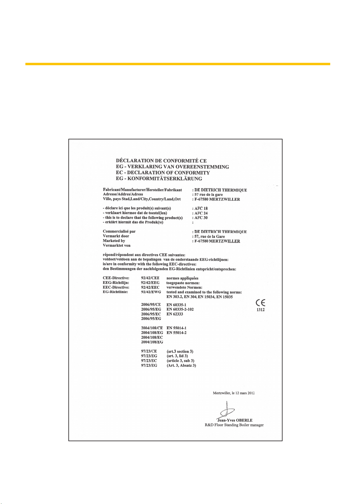
Declaration of conformity [
C003918-A
The device complies with the standard type described in
the EG declaration of conformity. It was manufactured and
commissioned in accordance with European directives.
The original declaration of conformity is available from the
manufacturer.
Page 3

Contents
1 Safety instructions .....................................................................................6
1.1 Safety instructions ...............................................6
1.2 Recommendations ................................................7
1.3 Liabilities ...............................................................8
1.3.1 Manufacturer’s liability .............................................8
1.3.2 Installer’s liability .....................................................8
2 About this manual ......................................................................................9
2.1 Symbols used .......................................................9
2.1.1 Symbols used in the manual ...................................9
2.1.2 Symbols used on the equipment .............................9
2.2 Abbreviations ......................................................10
2.3 After Sales Service Internet Site .......................10
3 Technical specifications ..........................................................................11
3.1 Homologations ....................................................11
3.1.1 Certifications .........................................................11
3.1.2 Oil category ...........................................................11
3.1.3 Additional Directives ..............................................11
3.1.4 Factory test ...........................................................12
3.2 Technical specifications ....................................12
3.2.1 Boiler specifications ..............................................12
3.2.2 Burner specifications .............................................14
3.2.3 Sensor characteristics ...........................................14
4 Product description .................................................................................15
4.1 General description ............................................15
4.2 Operating principle .............................................15
4.2.1 Skeleton Diagrams ................................................15
4.2.2 Circulation pump ...................................................20
4.2.3 Water flow rate ......................................................20
4.2.4 Burner operating cycle ..........................................20
09/07/2015 - 300026439-07
4.3 Main parts ............................................................25
4.3.1 Boiler .....................................................................25
4.3.2 Fuel oil burner .......................................................26
4.4 Package list .........................................................26
4.4.1 Standard delivery ..................................................26
4.4.2 Accessories ...........................................................27
1
Page 4

Contents
5 Installation ................................................................................................29
5.1 Regulations governing installation ...................29
5.2 Choice of the location ........................................30
5.2.1 Type plate .............................................................30
5.2.2 Positioning of the appliance ..................................30
5.2.3 Ventilation .............................................................32
5.2.4 Main dimensions ...................................................33
5.3 Positioning the appliance ..................................36
5.3.1 Positioning the boiler on its own ............................36
5.3.2 Fitting the boiler to a DHW tank ............................39
5.3.3 Positioning the boiler to the left or right of a DHW
tank .......................................................................39
5.3.4 Reversal of the direction the control panel access
door opens ............................................................40
5.4 Hydraulic connections .......................................43
5.4.1 Flushing the system ..............................................43
5.4.2 Connecting the expansion vessel
(Depending on country, standard delivery or
optional) ................................................................44
5.4.3 Installing the deaerator ..........................................45
5.4.4 Hydraulic connection of the heating circuit ............46
5.4.5 Connection of the water circuit for domestic
use ........................................................................46
5.4.6 Connecting the condensate discharge pipe ..........46
5.4.7 Filling the condensate trap ....................................48
5.5 Oil connection .....................................................48
5.5.1 General .................................................................48
5.5.2 Connecting ............................................................49
5.5.3 Diameter and length of the oil pipes ......................49
5.6 Flue gas system connections - Depending on
country .................................................................50
5.6.1 Connections for the air and exhaust pipes - Forced
flow (forced flue) - Type C .....................................50
5.6.2 Connections for the air and exhaust pipes - Single
flow (chimney) - Type B ........................................52
5.7 Installing the outside sensor .............................57
5.7.1 Choice of the location ............................................57
5.7.2 Connecting the outside sensor ..............................58
5.8 Electrical connections ........................................59
5.8.1 Control unit ............................................................59
5.8.2 Recommendations ................................................60
5.8.3 Accessing the connection terminal blocks ............60
5.8.4 Connecting a direct heating circuit ........................62
5.8.5 Connecting a direct circuit and a circuit with 3-way
valve ......................................................................63
5.8.6 Connecting a direct heating circuit and a domestic hot
water tank ..............................................................65
5.8.7 Connecting a direct heating circuit and an
independent domestic hot water tank ...................68
09/07/2015 - 300026439-07
2
Page 5

5.8.8 Connecting two circuits and a domestic hot water
tank .......................................................................70
5.8.9 Connecting two heating circuits with pressure
breaker ..................................................................72
5.8.10 Hot water storage tank connection ........................73
5.8.11 Pool connection .....................................................80
5.8.12 Connecting a mixed tank .......................................82
5.8.13 Connecting the options .........................................83
5.8.14 Connection in cascade ..........................................84
5.9 Electrical diagram ...............................................86
5.9.1 Boiler .....................................................................86
5.9.2 Burner ...................................................................88
5.10 Filling the system ...............................................89
5.10.1 Water treatment ....................................................89
5.10.2 Filling the heating circuit ........................................90
5.10.3 Filling the drinking water circuit .............................91
6 Commissioning ........................................................................................92
6.1 Control panel .......................................................92
6.1.1 Description of the keys ..........................................92
6.1.2 Description of the display ......................................93
6.1.3 Access to the various browsing levels ..................96
6.1.4 Browsing in the menus ..........................................97
6.2 Checks and settings before
commissioning ...................................................98
6.2.1 Preparing the boiler for commissioning .................98
6.3 Putting the appliance into operation ................98
6.4 Setting the burner ...............................................99
6.4.1 Operations to be carried out before any attempt to set
the burner ..............................................................99
6.4.2 Setting the burner’s 3 operating outputs .............100
6.4.3 Checking combustion ..........................................101
6.5 Checks and adjustments after
commissioning .................................................102
6.5.1 Displaying the parameters in extended
mode ...................................................................102
6.5.2 Setting the parameters specific to the
installation ...........................................................102
6.5.3 Naming the circuits and generators ....................107
6.5.4 Setting the heating curve ....................................108
6.5.5 Finalizing work ....................................................110
6.6 Reading out measured values .........................110
09/07/2015 - 300026439-07
6.7 Changing the settings ......................................111
6.7.1 Language selection .............................................112
6.7.2 Calibrating the sensors .......................................112
6.7.3 Professional settings ...........................................114
6.7.4 Configuring the network ......................................122
6.7.5 Return to the factory settings ..............................125
3
Page 6

Contents
7 Switching off the appliance ...................................................................126
7.1 Installation shutdown .......................................126
7.2 Antifreeze protection ........................................126
8 Checking and maintenance ...................................................................128
8.1 General instructions .........................................128
8.2 Chimney sweep instructions ...........................128
8.3 Customising maintenance ...............................129
8.3.1 Maintenance message ........................................129
8.3.2 Contact details of the professional for After Sales
Support ................................................................131
8.4 Standard inspection and maintenance
operations .........................................................131
8.4.1 Checking the hydraulic pressure .........................132
8.4.2 Checking the tightness of the flue gas discharge, the
air inlet and the condensates discharge ..............132
8.4.3 Checking the automatic air vent ..........................132
8.4.4 Cleaning of the heating body ..............................133
8.4.5 Cleaning the siphon ............................................137
8.4.6 Checking and replacing the installation’s oil
filter .....................................................................138
8.4.7 Maintenance of the burner ..................................138
8.5 Specific maintenance operations ....................142
8.5.1 Replacing the ignition electrodes ........................143
8.5.2 Maintenance of the air/flue gas drain connection
flues .....................................................................144
9 Troubleshooting .....................................................................................145
9.1 Anti-hunting ......................................................145
9.2 Messages (Code type Bxx or Mxx) ..................145
9.3 Message history ................................................148
9.4 Faults (Code type Lxx or Dxx) .........................148
9.4.1 Deletion of sensors from the memory in the
PCB .....................................................................154
9.5 Failure history ...................................................155
9.6 Parameter and input/output check (mode
tests) ..................................................................156
9.6.1 Control system sequence ....................................159
09/07/2015 - 300026439-07
4
Page 7

10 Spare parts ..............................................................................................161
10.1 General ..............................................................161
10.2 Spare parts ........................................................162
10.2.1 Boiler body - Tank - Base - Fuel oil burner .........162
10.2.2 Hydraulics ...........................................................165
10.2.3 Expansion vessel 18 litres (Depending on country,
standard delivery or optional) ..............................166
10.2.4 Casing .................................................................167
10.2.5 Control panel .......................................................168
10.2.6 Fuel oil burner (Details) .......................................169
10.2.7 Spare parts list ....................................................170
11 Appendix – Information on the Ecodesign and Energy Labelling
Directives ................................................................................................174
09/07/2015 - 300026439-07
5
Page 8
1. Safety instructions AFC 18 - AFC 24 - AFC 30
1 Safety instructions
1.1 Safety instructions
DANGER
This appliance can be used by children aged
from 8 years and above and persons with
reduced physical, sensory or mental capabilities
or lack of experience and knowledge if they have
been given supervision or instruction concerning
use of the appliance in a safe way and
understand the hazards involved. Children shall
not play with the appliance. Cleaning and user
maintenance shall not be made by children
without supervision.
DANGER
If you smell flue gases:
1. Switch the appliance off.
2. Open the windows.
3. Trace possible leaks and seal them
immediately.
WARNING
Depending on the settings of the appliance:
4 The temperature of the flue gas conduits
may exceed 60°C.
4 The temperature of the radiators may reach
95°C.
4 The temperature of the domestic hot water
may reach 80°C (depending on the set point
temperature and activation of the
antilegionella function).
CAUTION
4 Before any work, switch off the mains supply
to the appliance.
4 Avoid direct contact with the flame viewport.
6
09/07/2015 - 300026439-07
Page 9
AFC 18 - AFC 24 - AFC 30
1.2 Recommendations
1. Safety instructions
WARNING
4 Installation and maintenance of the boiler
must be carried out by a qualified
professional in compliance with prevailing
local and national regulations.
4 When carrying out work on the boiler,
always switch off the boiler at the mains and
close the main oil inlet.
4 After maintenance or repair work, check all
installations to ensure that there are no
leaks.
CAUTION
The boiler must be installed in a frost-free
environment.
Keep this document close to the place where the
boiler is installed.
Casing components
Only remove the casing for maintenance and repair
operations. Put the casing back in place after
maintenance and repair operations.
Instructions stickers
The instructions and warnings affixed to the appliance
must never be removed or covered and must remain
legible during the entire lifespan of the appliance.
Immediately replace damaged or illegible instructions and
warning stickers.
Modifications
Modifications to the boiler may only be carried out with the
written approval of your supplier.
09/07/2015 - 300026439-07
7
Page 10

1. Safety instructions
1.3 Liabilities
AFC 18 - AFC 24 - AFC 30
1.3.1. Manufacturer’s liability
Our products are manufactured in compliance with the
requirements of the various applicable European
Directives. They are therefore delivered with [ marking
and all relevant documentation.
In the interest of customers, we are continuously
endeavouring to make improvements in product quality.
All the specifications stated in this document are therefore
subject to change without notice.
Our liability as the manufacturer may not be invoked in the
following cases:
4 Failure to abide by the instructions on using the
appliance.
4 Faulty or insufficient maintenance of the appliance.
4 Failure to abide by the instructions on installing the
appliance.
1.3.2. Installer’s liability
The installer is responsible for the installation and
commissioning of the appliance. The installer must
respect the following instructions:
4 Read and follow the instructions given in the manuals
provided with the appliance.
4 Carry out installation in compliance with the prevailing
legislation and standards.
4 Perform the initial start up and carry out any checks
necessary.
4 Explain the installation to the user.
4 If a maintenance is necessary, warn the user of the
obligation to check the appliance and maintain it in
good working order.
4 Give all the instruction manuals to the user.
8
09/07/2015 - 300026439-07
Page 11
D000241-C
AFC 18 - AFC 24 - AFC 30
2 About this manual
2.1 Symbols used
2.1.1. Symbols used in the manual
In these instructions, various danger levels are employed to draw the
user’s attention to particular information. In so doing, we wish to
safeguard the user’s safety, highlight hazards and guarantee correct
operation of the appliance.
2. About this manual
DANGER
Risk of a dangerous situation causing serious physical
injury.
WARNING
Risk of a dangerous situation causing slight physical
injury.
CAUTION
Risk of material damage.
Signals important information.
¼Signals a referral to other instructions or other pages in the
instructions.
2.1.2. Symbols used on the equipment
4
~
Protective earthing
Alternating current
Before installing and commissioning the device, read
carefully the instruction manuals provided.
Dispose of the used products in an appropriate recovery
and recycling structure.
09/07/2015 - 300026439-07
This appliance must be connected to the protective earth.
9
Page 12

1 2
M002628-A
2. About this manual AFC 18 - AFC 24 - AFC 30
Caution: danger, live parts.
Disconnect the mains power prior to any operations.
2.2 Abbreviations
4 3CE: Collective conduit for sealed boiler
4 3WV: 3-way valve
4 PCU: Primary Control Unit - PCB for managing burner operation
4 PSU: Parameter Storage Unit - Parameter storage for PCBs
PCU and SU
4 SCU: Secondary Control Unit - DIEMATIC iSystem control panel
PCB
4 SU: Safety Unit - Safety PCB
4 DHW: Domestic hot water
4 Hi: Lower heating value LHV (Nett)
4 Hs: Higher heating value HHV (Gross)
4 HL: High Load - DHW tank with plate exchanger
4 SL: Standard Load - DHW tank with coil
4 SHL: Solar High Load - Solar DHW tank with plate exchanger
4 MC: Boiler module
4 CFC: Chlorofluorocarbon
2.3 After Sales Service Internet Site
The QR code or flashcode is used to access the internet site
containing the documentation and technical information regarding the
product. The QR code also appears on the appliance’s nameplate.
10
09/07/2015 - 300026439-07
Page 13
AFC 18 - AFC 24 - AFC 30 3. Technical specifications
3 Technical specifications
3.1 Homologations
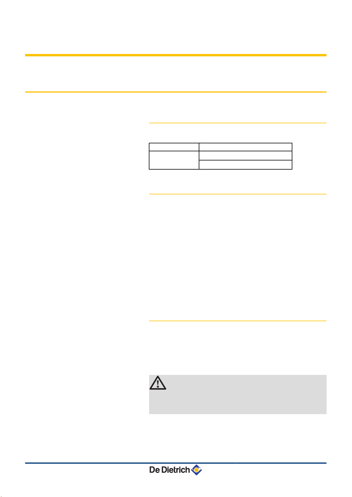
3.1.1. Certifications
CE identification no
Type of connection Chimney: B23, B
CE : 1312 CN 5691
Flue gas outlet: C
23P
13(x)
, C
33(x)
, C
93(x)
3.1.2. Oil category
4 Standard oil as well as low sulfur content oil (max. viscosity 6 mm²/
s at 20°C)
4 Bio-oil max. B10 (max. viscosity 6 mm2/s at 20°C).
- The bio-fuel oil B10 (or Bio 10) is a mixture of fuel oil with low
sulfur content (< 50 mg/kg) supplemented with 5.9 to 10.9 %
FAME* (% in volume).
- The bio-fuel oil B5 (or Bio 5) is a mixture of fuel oil with low sulfur
content (< 50 mg/kg) supplemented with 3 to 5.9 % FAME* (%
in volume).
- FAME* is produced from vegetable oil or processed animal fat.
EMAG: Fatty Acid Methyl Ester (also called EMAG : Ester
Méthylique d’Acide Gras).
3.1.3. Additional Directives
09/07/2015 - 300026439-07
Apart from the legal provisions and Directives, the additional
Directives described in these instructions must also be observed.
For all provisions and Directives referred to in these instructions, it is
agreed that all addenda or subsequent provisions will apply at the
time of installation.
WARNING
Installation of the appliance must be done by a qualified
engineer in accordance with prevailing local and national
regulations.
11
Page 14

3. Technical specifications AFC 18 - AFC 24 - AFC 30
3.1.4. Factory test
Before leaving the factory, each boiler is set for optimum performance
and tested to check the following items:
4 Electrical safety
4 Adjustment (CO2)
4 Water tightness
4 Oil tightness
4 Checked the tightness of the combusted gas outlet and air inlet
4 Parameter settings.
On commissioning, the installer is responsible for checking
the items mentioned above and, where necessary,
correcting them.
3.2 Technical specifications
3.2.1. Boiler specifications
Test conditions:
4 CO2 of 12% at min output and 13% at max output with oil.
4 Maximum operating pressure - Primary circuit (heating water):
3 bar (0.3 MPa)
4 Maximum operating temperature: 85 °C
4 Boiler temperature: Adjustable from 30 to 90 °C
4 Safety thermostat: 105 °C
4 Min flow temperature: 20°C
4 Min. return temperature : 20°C
4 Ambient temperature: 20 °C
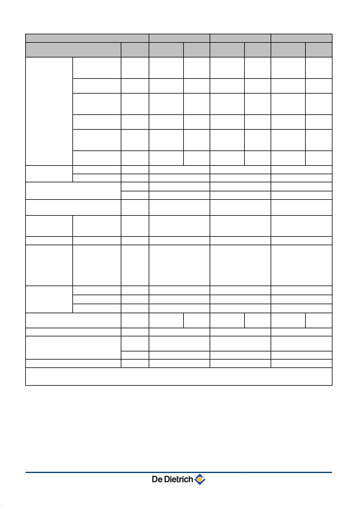
Boiler
Power input (Hi) kW 10.4 17.6 13.9 23.5 17.4 29.4
Nominal output (Pn) at 40/30°C kW 10.7 18.2 14.3 24.3 17.8 30.3
Nominal output (Pn) at 50/30°C
Nominal output (Pn) at 80/60°C kW 10 17.1 13.4 22.8 16.7 28.6
(1) These values are pertinent for flexible flue gas evacuation systems with a diameter of 80 mm (rigid ducts). The length of rigid flue gas
evacuation systems is restricted to 18 metres for technical reasons relating to start-up.
(2) 1 mbar = 10 mmWG = 100 Pa
kW
AFC 18 AFC 24 AFC 30
Minimum
power
10.6 18 14.1 24 17.6 30
Full
power
Minimum
power
Full
power
Minimum
power
Full
power
12
09/07/2015 - 300026439-07
Page 15
AFC 18 - AFC 24 - AFC 30 3. Technical specifications
Boiler AFC 18 AFC 24 AFC 30
LHV efficiency 100 % Nominal
Minimum
power
% 96.3 97.2 96.4 97.1 95.9 97.4
Full
power
Minimum
power
Full
power
Minimum
power
Full
power
output (Pn) at
80/60°C
Flue gas
°C <60 <70 <60 <70 <65 <75
temperature
100 % Nominal
% 101.5 102.1 101.4 102 101.1 101.6
output (Pn) at
50/30°C
Flue gas
°C <40 <45 <40 <45 <45 <50
temperature
100 % Nominal
% 102.9 103.5 102.6 103.2 102.5 103
output (Pn) at
40/30°C
Flue gas
°C <40 <45 <40 <45 <45 <50
temperature
Annual efficiencyHiat 75/60°C % 101.1 100.9 100.7
at 40/30°C % 105.3 105.1 104.6
Pressure available at the flue gas
nozzle (Pn)
CO2 content (Minimum output - Start-
(1)
mbar
0.14 0.22 0.33
Pa 14 22 33
% 12 - 13 - 13 12 - 13 - 13 12 - 13 - 13
up output - Maximum output
Nominal water
ΔT = 20K
m3/h
0.773 1.032 1.291
flow rate at Pn
(50/30 °C)
Stand-by losses ΔT = 30K W 109 109 128
Percentage of
ΔT = 30K % 61 61 63
losses through
the walls
compared with
the stand-by
losses
Loss of load
hydraulic circuit
(Pn)
ΔT = 10K
ΔT = 15K
ΔT = 20K
Electrical power of the boiler only with
(2)
mbar
mbar
mbar
66.0 117.0 183.0
(2)
29.0 52.0 81.0
(2)
16.0 29.0 46.0
W 128 272 128 272 128 272
no accessories
Water content litres 47 47 58
Mass flue gas flow rate (Nominal
output Pn 50/30 °C)
kg per
sec
0.0075 0.01 0.0125
Kg/h 27 36 45
Net weight (without packaging) kg 117 117 135
(1) These values are pertinent for flexible flue gas evacuation systems with a diameter of 80 mm (rigid ducts). The length of rigid flue gas
evacuation systems is restricted to 18 metres for technical reasons relating to start-up.
(2) 1 mbar = 10 mmWG = 100 Pa
09/07/2015 - 300026439-07
13
Page 16
3. Technical specifications AFC 18 - AFC 24 - AFC 30
3.2.2. Burner specifications
Modulating burner F10E2-5.18 +
AFC 18
F10E2-5.24 +
AFC 24
F10E2-5.30 +
AFC 30
Operation Modulating Modulating Modulating
Nominal output
Fuel flow
(2)
(1)
kW 10.4 - 17.6 13.9 - 23.5 17.4 - 29.4
Kg/h 0.9 - 1.5 1.2 - 2.0 1.5 - 2.5
Modulation range % 59 - 100 59 - 100 59 - 100
air nozzle Ø 19 22 26
Nozzle Danfoss (80°S) USG 0.30 0.40 0.50
Modulating oil pump Manufacturer’s pressure margin bar (MPa) 7 - 20
(0.7 - 2.0)
Max depression bar (MPa) 0.35
(0.035)
Max permitted pressure on entry bar (MPa) 2
(0.2)
Max permitted pressure on blocking bar (MPa) 2
(0.2)
7 - 22
(0.7 - 2.2)
0.35
(0.035)
2
(0.2)
2
(0.2)
7 - 22
(0.7 - 2.2)
0.35
(0.035)
2
(0.2)
2
(0.2)
Max pump air flow at 10 bar (1 MPa) l/h 45 45 45
(1) Power at an altitude of 400 m and at a temperature of 20°C. Heating value of fuel oil: LHV = 11,86 kWh/kg
(2) Bio-oil max. B10 (max. viscosity 6 mm2/s at 20°C)
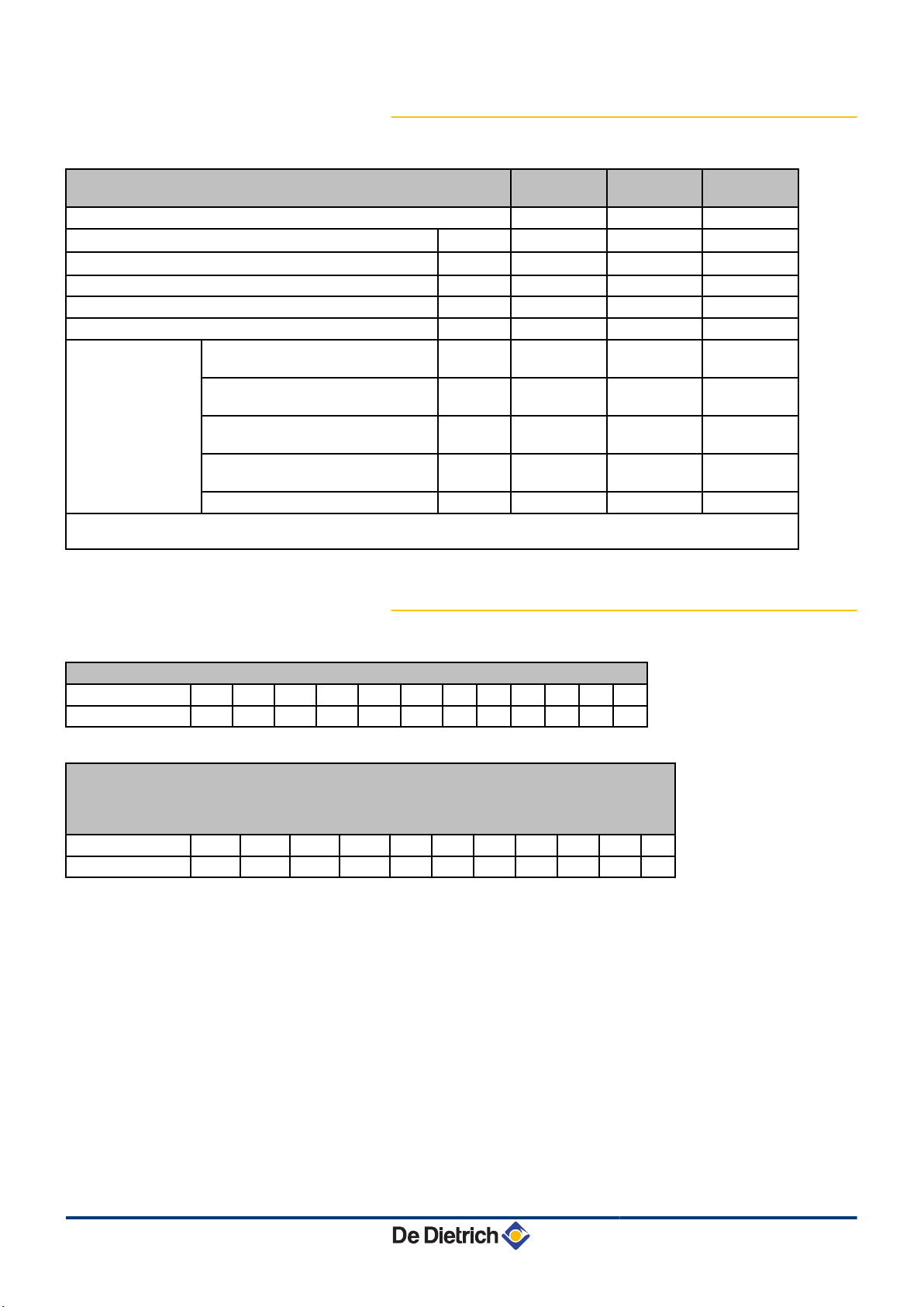
3.2.3. Sensor characteristics
Outside sensor
Temperature in °C -20 -16 -12 -8 -4 0 4 8 12 16 20 24
Resistance in Ω 2392 2088 1811 1562 1342 1149 984 842 720 616 528 454
Outlet sensor circuit B+C
Domestic hot water sensor
System sensor
Flow sensor - Return sensor NTC
Temperature in °C 0 10 20 25 30 40 50 60 70 80 90
Resistance in Ω 32014 19691 12474 10000 8080 5372 3661 2535 1794 1290 941
14
09/07/2015 - 300026439-07
Page 17
C003130-G
2
1
4
5
6
8
9
7
10
3
11
AFC 18 - AFC 24 - AFC 30 4. Product description
4 Product description
4.1 General description
Floor-standing condensing oil boiler
4 Heating only (Optional domestic hot water production in
combination with a DHW tank).
4 High efficiency heating.
4 Low pollutant emissions.
4 Modulating oil burner preassembled and preset.
4 Stainless steel heating body.
4 Top of the range electronic DIEMATIC iSystem control panel.
4 Flue gas discharge via a forced flue or chimney type connection.
4.2 Operating principle
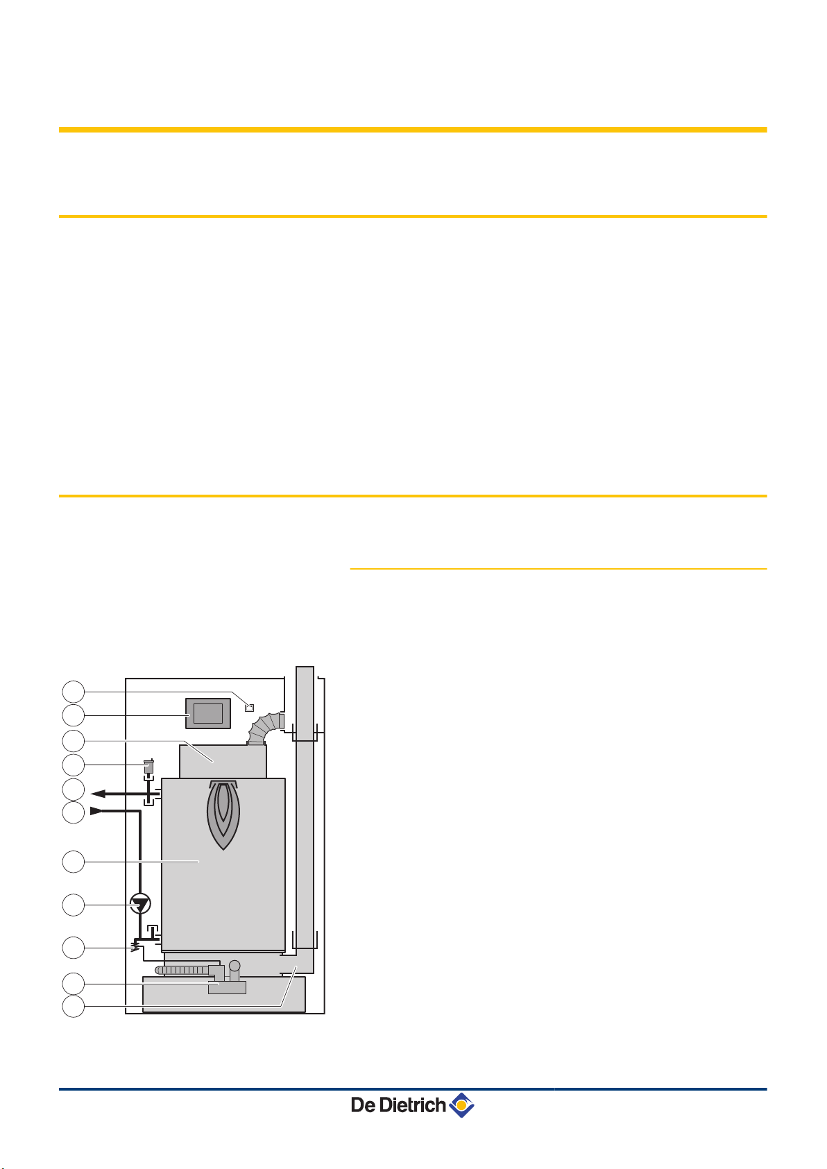
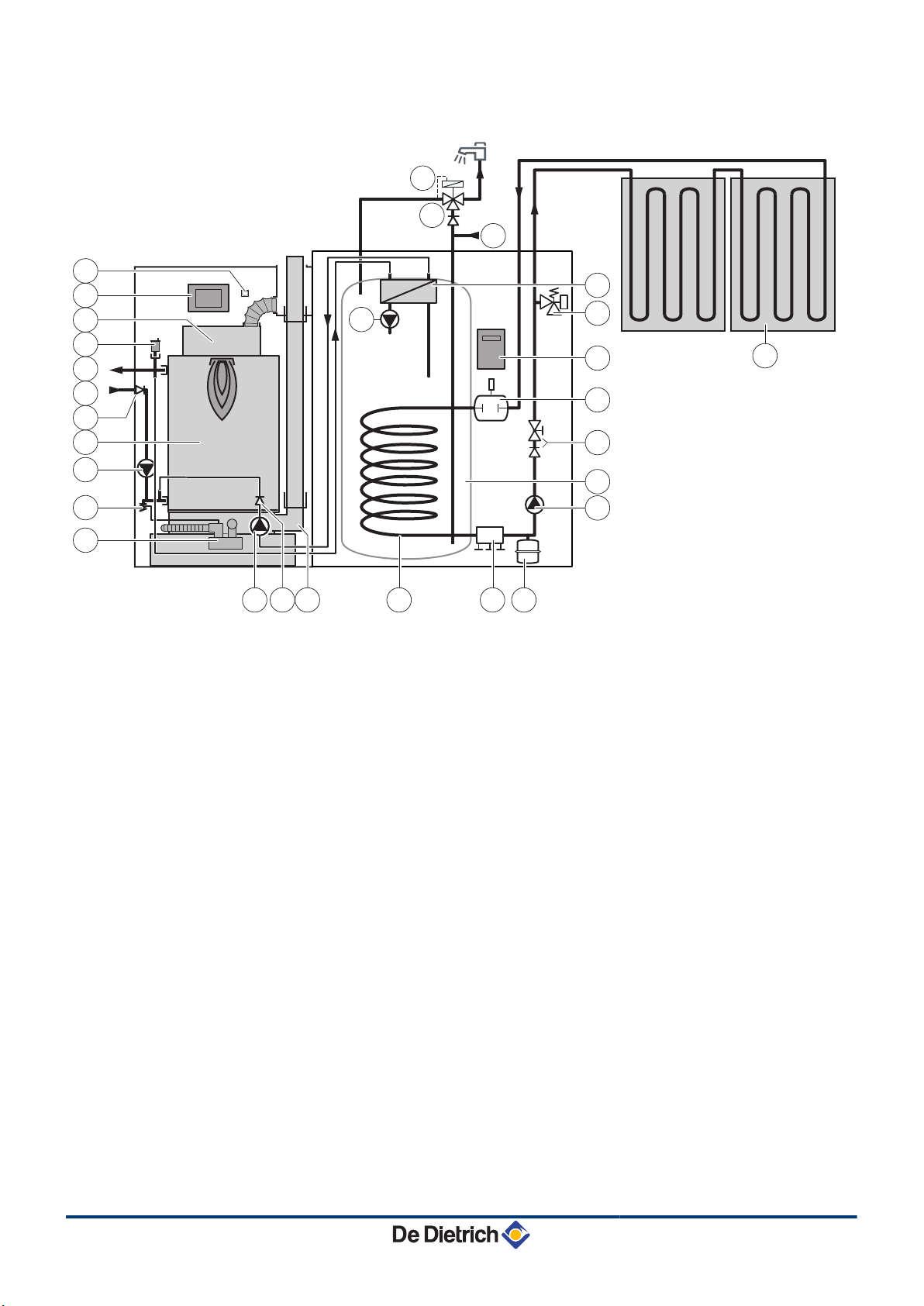
4.2.1. Skeleton Diagrams
Boiler self-standing - Circuit A
n
1
2
3
4
5
6
7
8
9
10
11
On/Off switch
Control panel
Burner
Automatic air vent
Heating flow
Heating return
Heating body
Circulation pump
0.3 MPa safety valve (3 bar)
Condensate trap
Flue gas discharge
09/07/2015 - 300026439-07
15
Page 18
12
C003131-i
4
5
6
3
8
9
7
13
14
15 1110
2
1
16
16
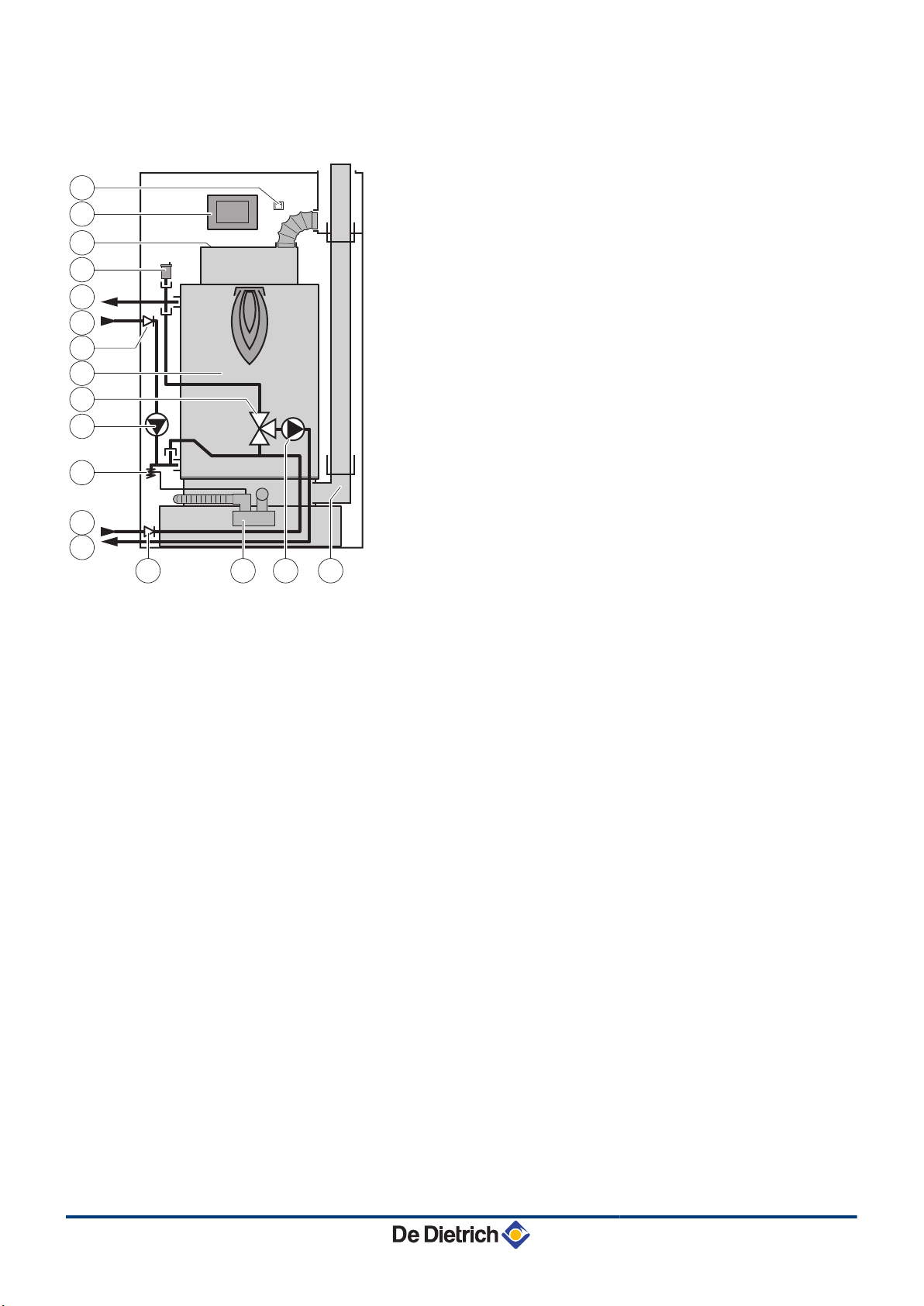
4. Product description AFC 18 - AFC 24 - AFC 30
Boiler with 3-way valve option - Circuit B (Option
n
integrable)
1
2
3
4
5
6
7
8
9
10
11
12
13
14
15
16
On/Off switch
Control panel
Burner
Automatic air vent
Heating flow direct circuit
Heating return direct circuit
Heating body
Direct circuit circulating pump
0.3 MPa safety valve (3 bar)
Condensate trap
Flue gas discharge
3-way valve
Heating return valve circuit
Heating flow valve circuit
Heating pump circuit mixing valve
Non-return valve
16
09/07/2015 - 300026439-07
Page 19
M002429-G
2
1
4
5
6
3
16
8
9
7
10
19
20
18
17
11
16
21
22
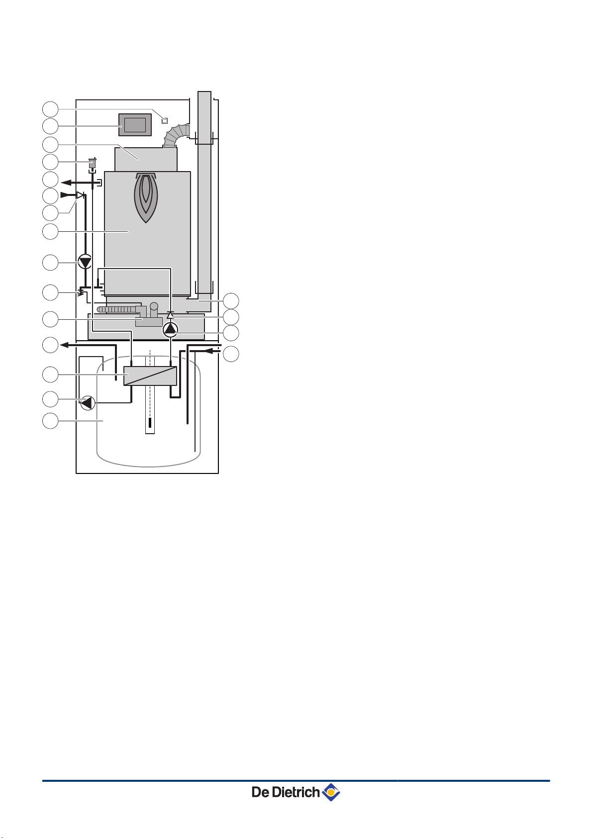
AFC 18 - AFC 24 - AFC 30 4. Product description
Boiler with 100HL type domestic hot water tank
n
1
2
3
4
5
6
7
8
9
10
11
16
17
18
19
20
21
On/Off switch
Control panel
Burner
Automatic air vent
Heating flow
Heating return
Heating body
Circulation pump
0.3 MPa safety valve (3 bar)
Condensate trap
Flue gas discharge
Non-return valve
Domestic hot water outlet
Plate heat exchanger
Domestic hot water pump
Domestic hot water tank
Primary domestic hot water load pump
22
Domestic cold water inlet
09/07/2015 - 300026439-07
17
Page 20
M002430-F
5
6
2
1
4
3
9
10
8
11
18 17
14
15
16
13712
7
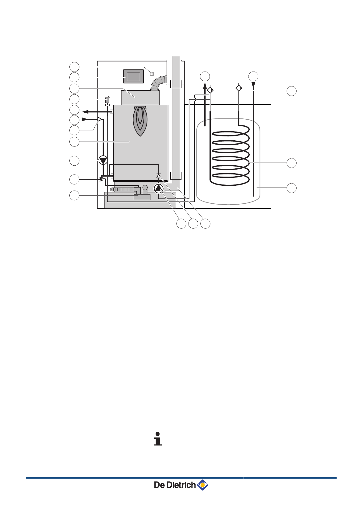
4. Product description AFC 18 - AFC 24 - AFC 30
Boiler with 160SL type domestic hot water tank
n
1
2
3
4
5
6
7
8
9
10
11
12
13
14
15
16
17
18
On/Off switch
Control panel
Burner
Automatic air vent
Heating flow
Heating return
Non-return valve
Heating body
Circulation pump
0.3 MPa safety valve (3 bar)
Condensate trap
Calorifier load pump
Flue gas discharge
Domestic hot water tank
Domestic water coil
Manual bleed valve
Domestic cold water inlet
Domestic hot water outlet
Configuration with a DHW tank also enables the
connection of a circuit with mixing valve.
18
09/07/2015 - 300026439-07
Page 21
C003834-C
2
1
3
4
5
6
8
9
7
10
11
12 7 13 1514
24
25
27
28
26
16
17
18
19
20
21
22
23
AFC 18 - AFC 24 - AFC 30 4. Product description
Boiler with 220SHL type domestic hot water tank
n
1
2
3
4
5
6
7
8
9
10
11
12
13
14
15
16
17
18
19
20
On/Off switch
Control panel
Burner
Automatic air vent
Heating flow
Heating return
Non-return valve
Heating body
Circulation pump
0.3 MPa safety valve (3 bar)
Condensate trap
Calorifier load pump
Flue gas discharge
Domestic water solar coil
Primary solar circuit filling and draining device
Solar expansion vessel 12 l
solar circulation pump
Domestic hot water tank
Antithermosiphon valve operated by the spherical plug
valve
Degasser with manual purge to the solar circuit drain
valve
09/07/2015 - 300026439-07
19
Page 22
M003250-A
(mbar)
(m3/h)
0
50
100
150
200
250
300
350
400
450
500
550
600
650
700
750
0 0,2 0,4 0,6 0,8 1 1,2 1,4 1,6 1,8 2 2,2 2,4 2,6 2,8 3 3,2 3,4 3,6
a
b
c
4. Product description AFC 18 - AFC 24 - AFC 30
21
22
23
24
25
26
27
28
Solar regulator
Solar safety valve
Plate heat exchanger
Solar collectors
Domestic cold water inlet
Non-return valve
Domestic hot water thermostatic mixing valve
DHW pump
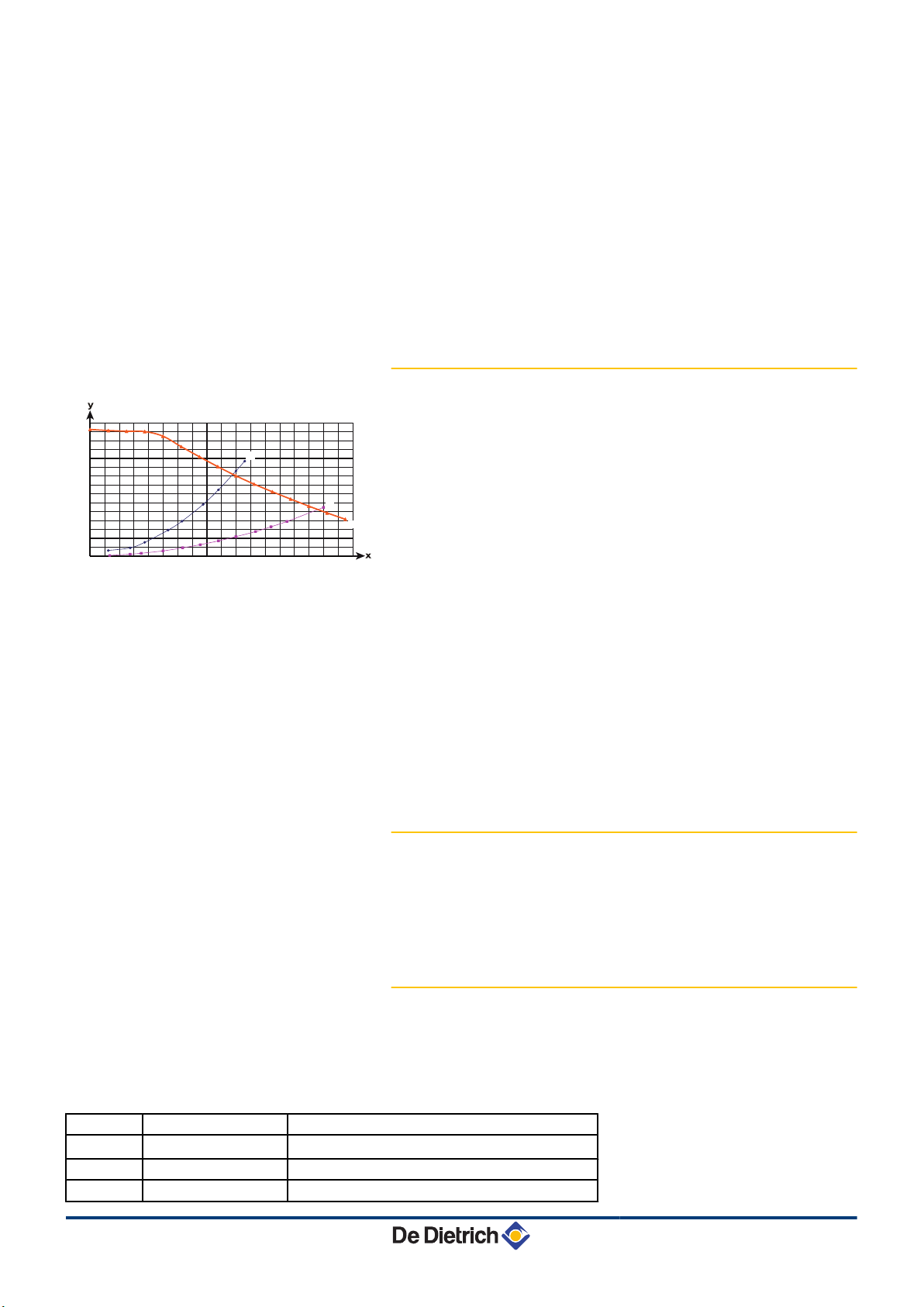
4.2.2. Circulation pump
a
b
c
x
y
Boiler pressure drop (with valve)
Boiler pressure drop (without valve)
Circulation pump (Class A pump)
Water flow
Manometric height central heating circuit
The boiler is fitted with a modulating pump which is regulated by the
control panel as a function of ΔT= (Flow T °C - Return T °C).
The graph shows the manometric height at various outputs. The
parameters MIN.PUMP SPEED and MAX.PUMP SPEED are used to
modify the pump settings. If flow noise can be heard in the system, it
is possible to reduce the maximum pump speed with the parameter
MAX.PUMP SPEED (First of all, vent the heating system). If
circulation in the radiators is too low or the radiators do not fully heat
up, increase the minimum pump speed with the parameter
MIN.PUMP SPEED.
¼See chapter: "Professional settings", page 114.
4.2.3. Water flow rate
The boiler’s modulating control system limits the maximum difference
in temperature between the heating flow and return and the maximum
speed at which the flow temperature increases. In this way, the boiler
does not require a minimum water flow rate.
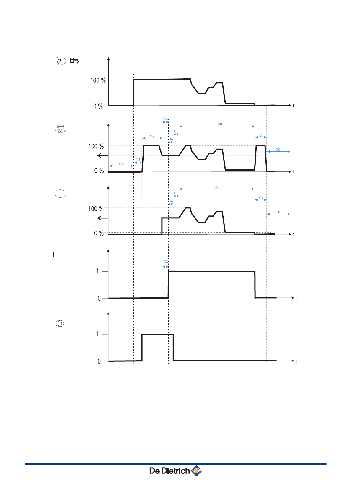
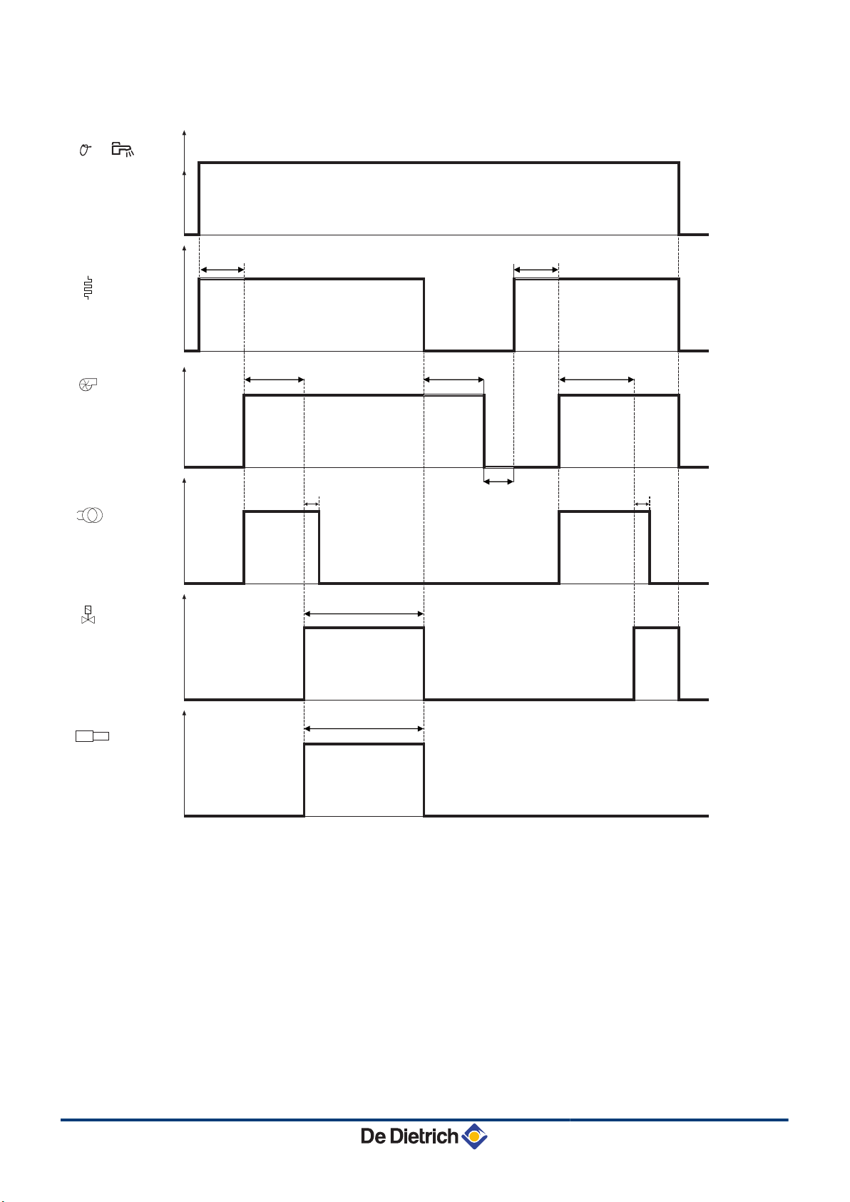
4.2.4. Burner operating cycle
Sequence
0r
2
1
20
Sequence displayed Description
x - x Heating request - Domestic hot water mode
x - x Fan speed
x - x Fuel oil pressure
Legend
n
09/07/2015 - 300026439-07
Page 23

AFC 18 - AFC 24 - AFC 30 4. Product description
3
Arc
D
OV
?
C0
C1
C2
C3
C4
C5
C6
C7
x - x Flame detection
x - x Ignition stage
x - x Start-up threshold
x - x Fuel pre-heater
x - x Anti-short cycle
x - x Burner off
2 - 13 Reheat fuel oil (Max 400 seconds)
2 - 14 Pre-ignition and preventilation time (15 seconds)
2 - 15 Electro-valve opening (No flame presence)
Max time: Safety time (TS = 5 seconds)
2 - 16 Post-ignition time (7 seconds)
2 - 17 Flame stabilisation (for 20 sec)
x - x Output modulation
5 - 41 Post-ventilation (120 seconds)
09/07/2015 - 300026439-07
21
Page 24
D
D
°
ITR
C003259-E
P. Oil
( )
Arc
4. Product description AFC 18 - AFC 24 - AFC 30
Normal start-up
n
22
09/07/2015 - 300026439-07
Page 25
D
C003223-E
D
°
ITR
P. Oil
Arc
AFC 18 - AFC 24 - AFC 30 4. Product description
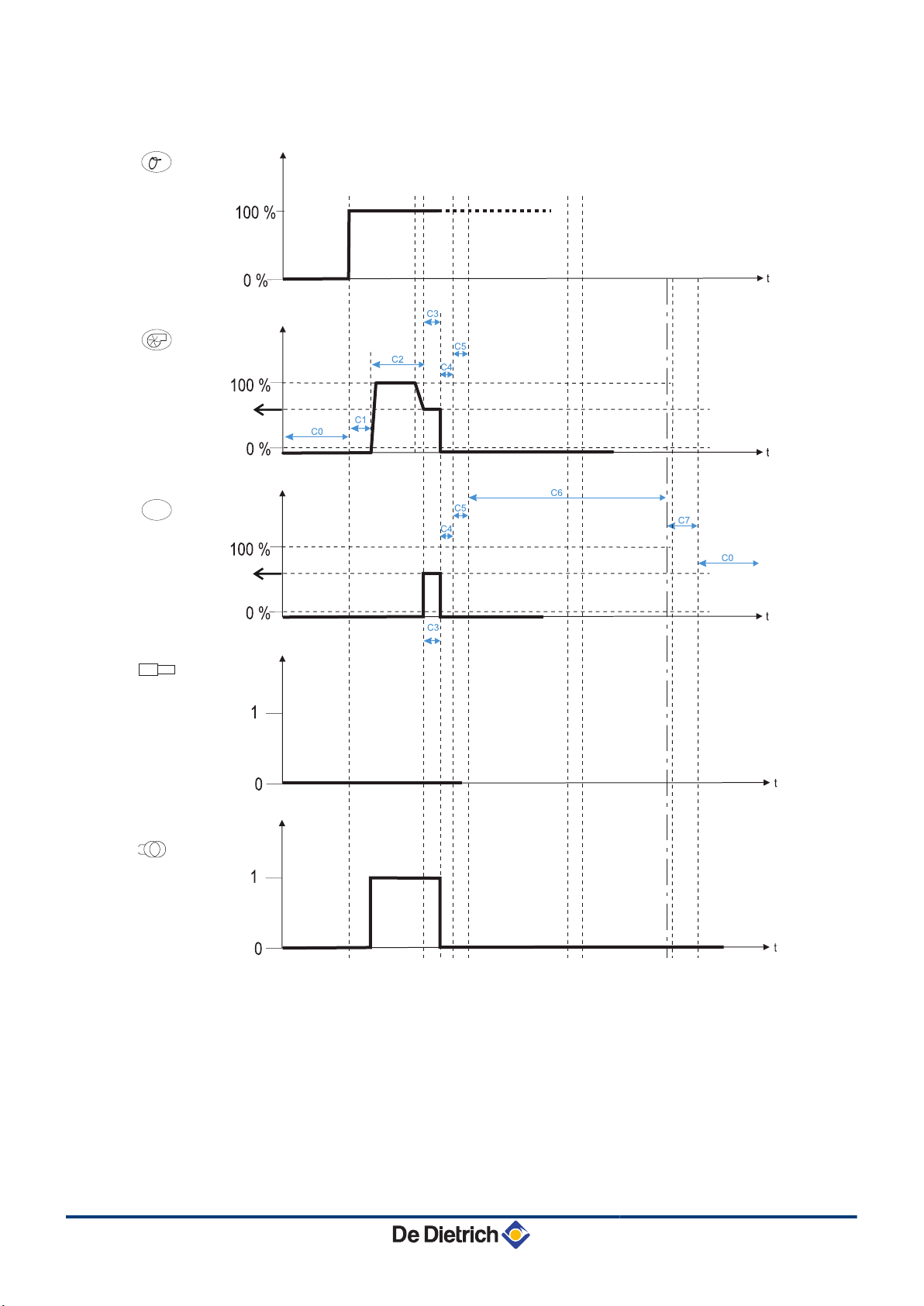
Start-up without flame detection
n
09/07/2015 - 300026439-07
23
Page 26
M003249-B
°
ITR
Arc
OV
( )
1
0
1
C1
C7
?
C1
0
1
0
1
0
1
0
1
0
C2
C4 C4
C2
C3
C5
4. Product description AFC 18 - AFC 24 - AFC 30
Loss of the flame signal whilst in operation
n
24
09/07/2015 - 300026439-07
Page 27
C003129-G
56
7
17
18
16
8
9
13
14
19
15
11
10
34 12
12
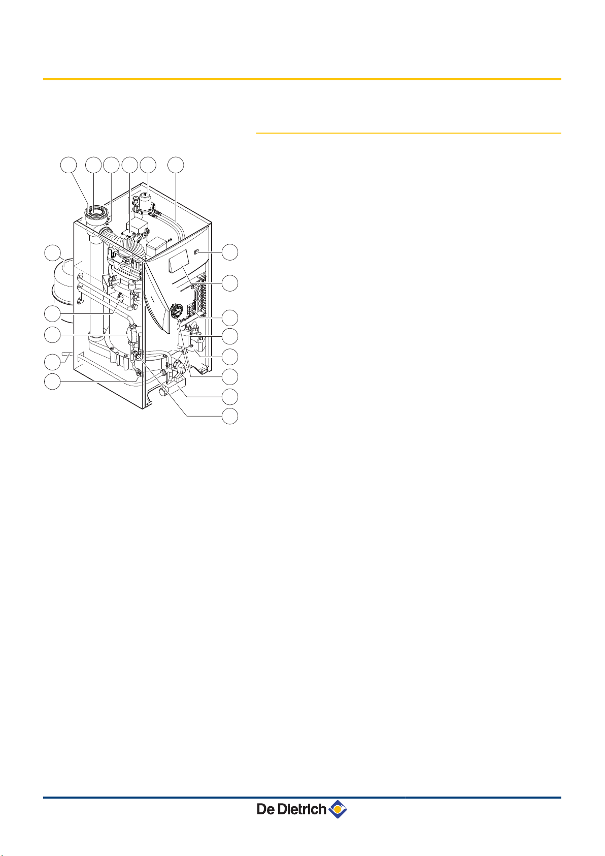
AFC 18 - AFC 24 - AFC 30 4. Product description
4.3 Main parts
4.3.1. Boiler
1
2
3
4
5
6
7
8
9
10
11
12
13
14
15
16
Fuel supply pipes
Oil filter (40 µm) + deaerator + stop valve
Modulating oil burner preassembled and preset
Flue gas measuring point / Combustive air
Flue gas discharge pipe (Diameter 80 mm)
Air intake (Diameter 125 mm)
Expansion vessel 18 litres
Electronic pressure sensor (Pressure in the heating
circuit)
Modulating heating pump
Condensates evacuation pipe
Drain cock
0.3 MPa safety valve (3 bar)
Condensate trap
Heating pump circuit mixing valve (Option)
Motorised 3-way mixing valve (Option)
Connection PCBs (PCU + SCU)
17
18
19
Command module
On/Off switch
Flue gas pressure switch
09/07/2015 - 300026439-07
25
Page 28
13
14
12
20
19
21
18
17
16
15
7
8
9
6
5
4
10
11
321
25
24
23
22
26
27
C003219-G
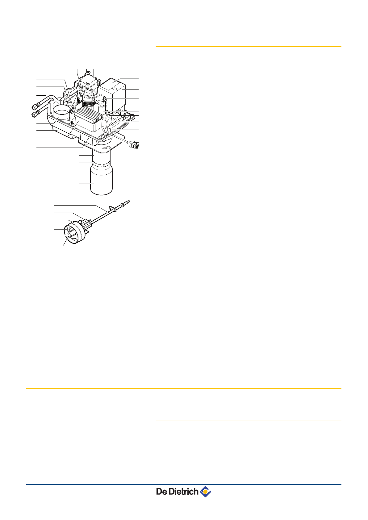
4. Product description
AFC 18 - AFC 24 - AFC 30
4.3.2. Fuel oil burner
1
2
3
4
5
6
7
8
9
10
11
12
13
14
15
16
Modulating motor
Pressure sensor
Modulating oil pump
Control box display - Not used
Burner control and safety box
Recirculation slot adjustment screw
Flame detection cell (IRD at 18 kW and BST at 24–30
kW)
Head air pressure measurement point
Ignition transformer
Door handle
BUS cable for connection to the control system
Flame tube
Recirculation slot
Burner pipe
Component plate
Modulating motor management box
4.4 Package list
17
18
19
20
21
22
23
24
25
26
27
Air enclosure
Air inlet
Fuel supply pipes
Door handle + Flexible mounting flange
Connector 230 V
Filling line
Pre-heater
Combustion head
air nozzle
Nozzle
Ignition electrode
4.4.1. Standard delivery
The delivery includes:
26
4 The assembled boiler with the burner
4 The oil filter + the deaerator + the stop valve
4 The outside sensor
09/07/2015 - 300026439-07
Page 29
AFC 18 - AFC 24 - AFC 30 4. Product description
4 The horizontal or vertical terminal (depending on the version)
4 The installation and maintenance instructions
4 The user instructions
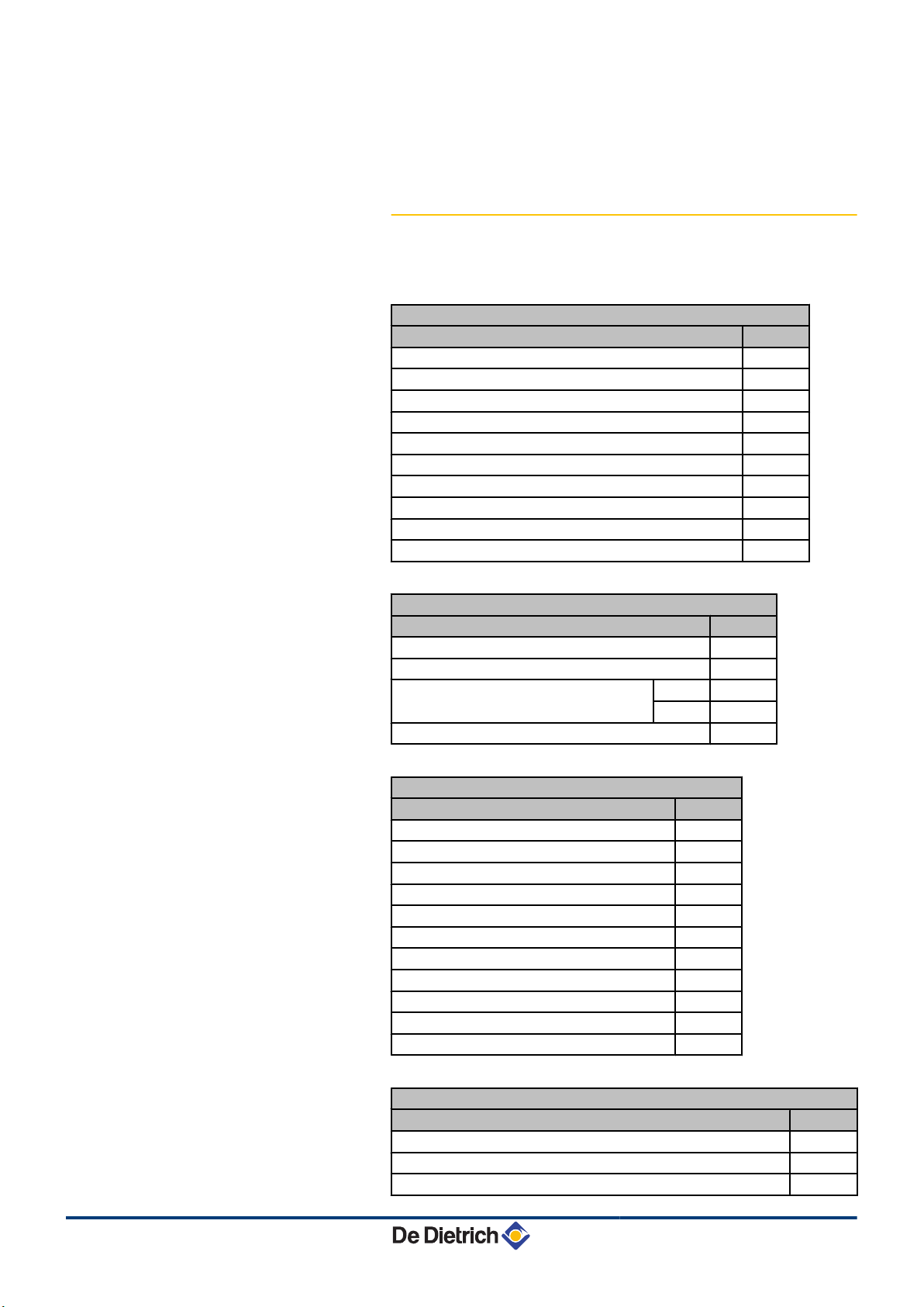
4.4.2. Accessories
Various options are available depending on the configuration of the
installation (Depending on country) :
Boiler options
Description package
Condensates neutralisation station FM155
Refill of 5 kg of granules and 0.5 kg of activated carbon FM156
Bracket for neutralisation station FM157
Condensates lift pump FM158
3-way internal valve kit MV5
External circuit kit MV6
Adapter kit for external heating pump MV30
3-way internal valve kit HEE - Class A pump MV31
DHW thermostatic mixing valve kit MV10
18-litre expansion vessel MV4
Flue gas system options
Description package
Chimney connection kit PPS diameter 80/110 mm DY876
Air/flue gas terminal horizontal forced flue FM183
Air/flue gas terminal vertical forced flue Black DY843
Red DY844
Back flue gas outlet kit MV9
Control system options
Description package
RX12 cable AD134
TELCOM2 voice remote monitoring module AD152
Flow sensor AD199
DHW sensor AD212
Optional PCB for 3-way valve AD249
Hot water storage tank sensor AD250
Outside radio-controlled temperature sensor AD251
Boiler radio module AD252
Radio remote control AD253
Interactive remote control AD254
Room sensor FM52
09/07/2015 - 300026439-07
Domestic hot water tank options
Description package
Domestic hot water tank 100HL ER225
Domestic hot water tank 160SL ER223
Solar domestic hot water calorifier 220SHL ER220
27
Page 30

4. Product description AFC 18 - AFC 24 - AFC 30
Domestic hot water tank options
Description package
100HL recirculation kit ER218
160SL/220SHL recirculation kit ER219
Boiler/DHW tank hydraulic connecting kit 100HL MV7
Boiler/DHW tank hydraulic connecting kit 160SL MV8
Boiler/DHW tank hydraulic connecting kit 160SL - HEE -
MV32
Class A pump
Connecting kit for external DHW tank - HEE - Class A pump MV33
Boiler/solar DHW tank hydraulic connecting kit 220SHL MV11
Boiler/DHW tank hydraulic connecting kit MV18
28
09/07/2015 - 300026439-07
Page 31

AFC 18 - AFC 24 - AFC 30
5 Installation
5.1 Regulations governing installation
WARNING
Installation of the appliance must be done by a qualified
engineer in accordance with prevailing local and national
regulations.
France:
Residential buildings
Statutory terms and conditions of installation and maintenance:
4 DTU 65-17
4 Local Sanitary Regulations
4 For appliances connected to the electricity network:
NF C 15-100 standards Low voltage electrical installation - Rules.
5. Installation
Establishments open to the public
Statutory terms and conditions of installation:
4 Safety regulations against fire and panic in establishments open
to the public
- General regulations:
Articles GZ - Installations operating on combustible gases and
liquefied hydrocarbons
Articles CH-Heating, ventilation, refrigeration, air conditioning
and production of steam and domestic hot water
- Instructions specific to each type of establishment open to the
public (hospitals, stores, etc.)
Germany:
Standards to be respected:
4 FeuVo decree, paragraph 3
4 DIN EN 12828 (June 2003 edition): heating systems in buildings.
Planning of hot water heating installations (up to a maximum
operating temperature of 105°C and a maximum output of 1 MW)
4 DIN 4753: drinking and industrial water heating installations
4 DIN 1988: technical rules on drinking water installations (TRW)
Switzerland:
09/07/2015 - 300026439-07
Standards to be respected:
4 Directives of the Association des Etablissements Cantonaux
d’Assurance Incendie AEAI.
4 Local and cantonal regulations.
29
Page 32

C003289-C
5. Installation
5.2 Choice of the location
AFC 18 - AFC 24 - AFC 30
The safety distance between combustible substances and the boiler
and gaseous effluents must comply with the requirements of the AEAI
standard.
5.2.1. Type plate
The nameplates must be accessible at all times. The nameplates
identify the product and provide the following information:
4 Type of product
4 Manufacturing date (Year - Week)
4 Serial number
4 CE identification no
30
One nameplate is affixed to the back of the appliance.
Affix the nameplate provided in the document bag to the
boiler casing where it can be seen.
5.2.2. Positioning of the appliance
CAUTION
When installing the appliance, respect the IP21
environmental rating.
4 Place the appliance on a base frame to facilitate cleaning of the
premises.
4 Allow enough space around the appliance to facilitate accessibility
and maintenance. The minimum recommended dimensions are
shown in the illustration in mm.
09/07/2015 - 300026439-07
Page 33

M002360-E
1700
min.500
320
min.
250
A
500
1100
min.500
320
min.
250
C
500
1100
min.500
320
685
min.
250
A
500
C003133-B
B
AFC 18 - AFC 24 - AFC 30 5. Installation
4 Install the appliance as close as possible to the drawing off points
in order to minimise energy losses through the pipes.
4 Make sure there is a connection to the sewage system close to
the boiler to evacuate the condensates.
CAUTION
Allow some free space behind the boiler to install the
following components:
4 The heating circuit expansion vessel
4 The oil filter + the deaerator + the stop valve
DHW calorifier type Boiler model
AFC 18 AFC 24 AFC 30
A (mm) - 1130 1130 1200
B (mm) 100HL - - -
160SL 921 921 921
220SHL 1201 1201 1201
C (mm) 100HL 1686 1686 1756
160SL - - 220SHL - - -
09/07/2015 - 300026439-07
31
Page 34

5. Installation AFC 18 - AFC 24 - AFC 30
5.2.3. Ventilation
CAUTION
In order to avoid damage to the boiler, it is necessary to
prevent the contamination of combustion air by chlorine
and/or fluoride compounds, which are particularly
corrosive. These compounds are present, for example, in
aerosol sprays, paints, solvents, cleaning products,
washing products, detergents, glues, snow clearing salts,
etc. Therefore:
4 Do not pull in air evacuated from premises using such
products: hairdressing salons, dry cleaners,
industrial premises (solvents), premises containing
refrigeration systems (risk of refrigerant leakage),
etc.
4 Do not stock such products close to the boilers.
If the boiler and/or peripheral equipment are corroded
by such chloride or fluoride compounds, the
contractual guarantee cannot be applied.
Type C - Forced flue version
n
If the evacuation of combusted gases and the intake of combustive
air are done using a concentric conduit, ventilation of the boiler room
is not necessary.
Condensing boilers require a flue gas discharge system or a fresh air
inlet specially adapted to the method of operation. Installation must
be carried out in accordance with current laws.
CAUTION
Do not block the air inlet, combustion product evacuation
or condensation water flow pipes (even partially).
Avoid any low points in the flue gas and condensates
discharge circuit in order to prevent any condensates
accumulation.
Type B - Open flue
n
Condensing boilers require a flue gas discharge system or a fresh air
inlet specially adapted to the method of operation. Installation must
be carried out in accordance with current laws.
32
Position the air inlets in relation to the high ventilation vents in order
that the air is refreshed throughout the boiler room.
CAUTION
4 Avoid any low points in the flue gas and condensates
discharge circuit in order to prevent any condensates
accumulation.
4 Do not block the air inlets in the room or the
combustion products evacuation or condensation
water flow pipes (even partially).
09/07/2015 - 300026439-07
Page 35

AFC 18 - AFC 24 - AFC 30 5. Installation
The minimum cross-sections and the positions of the fresh air inlet
and the air outlet must comply with prevailing regulations.
Generator installed in a building for collective use
n
(installations less than 70 kW)
4 The fresh air inlet must:
- Come out in the lower section of the premises,
- Have a free minimum cross section calculated on the basis of
0.03 dm² per kilowatt installed output and at least equal to 2.5
dm².
4 The air discharge must:
- Be located in the upper section of the premises,
- Rise above the roof (unless using an equivalent system which
does not cause a nuisance to neighbours),
- Have a free cross section (corresponding to 2/3 of that of the
air inlet and at least equal to 2.5 dm²).
Generator installed in a builing for individual use
n
Markers
A
Z
E
R
T
Y
P
a
z
4 An adequate supply of fresh air must be provided as close as
possible to the appliances. Its cross section must be at least 0.5
dm².
4 In the upper section of the premises, an air outlet must ensure
effective ventilation.
Establishments open to the public
n
4 New establishment: Refer to the order of 25/06/1980 (installations
of more than 20 kW and less than or equal to 70 kW).
4 Existing establishment: Refer to the order of 25/06/1980
(installations less than 70 kW).
5.2.4. Main dimensions
Legend
n
Description Size
Heating flow direct circuit G 1
Heating return direct circuit G 1
Primary flow independent DHW tank (Option) G 3/4
Primary return independent DHW tank (Option) G 3/4
Heating flow circuit with mixing valve (Option) G 1
Heating return circuit with mixing valve (Option) G 1
Domestic cold water inlet G 3/4
Domestic hot water outlet G 3/4
DHW circulation loop return (Option) G 3/4
09/07/2015 - 300026439-07
33
Page 36

681
983
45
6998
302
600
A
B
472
(1)
410
160
83
346
6071005
681
83
2
1
6
16
19
5
4
3
C003135-H
520 435 163
93
84,5
(2)
308
69
102
54
56
128
17
128
18
5. Installation AFC 18 - AFC 24 - AFC 30
Markers Description Size
e
r
t
y
u
i
o
DHW drain valve External diameter: 14 mm
Primary solar coil inlet - Copper diameter: 18 mm
Primary solar coil outlet - Copper diameter: 18 mm
Oil supply G 3/8
Condensate discharge pipe External diameter: 25 mm
Low flue gas outlet diameter: 80 mm
Concentric air / flue gas connection diameter: 80/125 mm
(1) Adjustable feet 0 to 20 mm
(2) If mounting the oil filter with deaerator inside the casing
Boiler self-standing
n
Models
A (mm)
B (mm)
AFC 18 AFC 24 AFC 30
1130 1130 1200
1175 1175 1245
34
09/07/2015 - 300026439-07
Page 37

681
75
983
45
6998
302
600
A
B
472
(1)
(2)
1164
1240
640
300
584
1553
2
1
6
5
M002424-E
84,5
308
128
13
710
56
128
906
17
245 70
40
10
11
16
19
12
18
M002427-E
681
45
6998
983
302
1200
A
472
600
911
(1)
607
681
B
83
1005
2
1
5 6
84,5
308
(2)
78
300
870
245 69
12
16
19
13
10
11
520
435 163
93 69
128
160
56
54
17
346
126
18
AFC 18 - AFC 24 - AFC 30 5. Installation
Boiler with 100HL type domestic hot water tank
n
Models AFC 18 AFC 24 AFC 30
A (mm)
B (mm)
n
1686 1686 1756
1731 1731 1801
Boiler with 160SL type domestic hot water tank
Models
A (mm)
B (mm)
AFC 18 AFC 24 AFC 30
1130 1130 1200
1175 1175 1245
09/07/2015 - 300026439-07
35
Page 38

C003833-C
302
1005
83
128
160
55
346
245 70
40
11
10
12
15
14
6
5
(2)
B
45
983
681
6998
435 163
157
115
84,5
308
1105
1150
18,5
78
93 69
126
83
607
681
54
300
2
1
13
16
19
17
18
(1)
A
600600
472
1200
520 520
C003136-D
1
2
notice
handleiding
5. Installation AFC 18 - AFC 24 - AFC 30
Boiler with 220SHL type domestic hot water tank
n
Models AFC 18 AFC 24 AFC 30
A (mm)
B (mm)
1130 1130 1200
1175 1175 1245
5.3 Positioning the appliance
CAUTION
4 Have 2 people available.
4 Handle the appliance with gloves.
5.3.1. Positioning the boiler on its own
1. Remove the packaging from the boiler but leave the shipping pallet
in place.
2. Remove the protective packaging.
The technical documentation is housed in the protective
block.
The outside temperature sensor is housed in the protective
block.
36
09/07/2015 - 300026439-07
Page 39

C003137-G
4
3
C003138-G
6
6
5
AFC 18 - AFC 24 - AFC 30 5. Installation
3. Open the access door on the control panel.
4. Remove the front panel by pulling firmly from both sides.
5. Close the door.
6. Remove the front and back holding screws.
09/07/2015 - 300026439-07
37
Page 40

C003139-H
7
7
8
7
7
9
9
C003140-E
(1)
5. Installation AFC 18 - AFC 24 - AFC 30
7. Lower the boiler from the transport pallet using lifting bars. Use
steel tubes 3/4" in diameter and 1400 mm in length.
8. Install the appliance on the base provided.
9. Level the appliance using the adjustable feet.
(1) Adjustable feet, Basic dimension 30 mm
Can be adjusted from 20 mm to 40 mm.
10.Refit the front panel.
38
09/07/2015 - 300026439-07
Page 41

M002428-D
4
5
3
3
3
3
AFC 18 - AFC 24 - AFC 30
5. Installation
5.3.2. Fitting the boiler to a DHW tank
1. Put the DHW tank in place.
Refer to the DHW tank’s installation, use and maintenance
¼
instructions.
2. Carry out steps 1 to 8 described above.
See chapter "Positioning the boiler on its own"
¼
3. Lower the boiler from the transport pallet using lifting bars. Use
steel tubes 3/4" in diameter and 1400 mm in length.
4. Position the boiler on the DHW tank.
5. Put the retaining screws in place.
6. Refit the front panel.
5.3.3. Positioning the boiler to the left or right of
a DHW tank
1. Put the DHW tank in place.
Refer to the DHW tank’s installation, use and maintenance
¼
instructions.
2. Put the boiler in place.
See chapter "Positioning the boiler on its own".
¼
09/07/2015 - 300026439-07
39
Page 42

1
C003099-D
C003121-C
2
C003285-B
3
3
5. Installation AFC 18 - AFC 24 - AFC 30
5.3.4. Reversal of the direction the control panel
access door opens
As standard, the control panel access door opens to the left. To open
the control panel access door to the right, proceed as follows:
1. Open and remove the control panel door.
2. Take the control system module out of its housing and disconnect
it.
3. Unscrew the mounting screws at the back of the top panel:
- Boiler 18 kW / 24 kW = 2 screws
- Boiler 30 kW = 3 screws.
Remove the top panel.
40
09/07/2015 - 300026439-07
Page 43

C003160-F
4
5
5
4
C003161-C
180°
6
6
C003162-E
8
7
7
AFC 18 - AFC 24 - AFC 30 5. Installation
4. Tilt the control panel forwards.
5. Unscrew the screws holding the front of the control unit.
6. Pivot the holder by 180°.
7. Retighten the fastening screws on the control panel.
8. Tilt the control panel.
09/07/2015 - 300026439-07
41
Page 44

C003286-B
9
9
C003163-B
10
C003164-D
11
5. Installation AFC 18 - AFC 24 - AFC 30
9. Replace the top.
10.Reconnect and put the control system module back in place.
11.Refit the control panel door.
42
09/07/2015 - 300026439-07
Page 45

AFC 18 - AFC 24 - AFC 30 5. Installation
5.4 Hydraulic connections
5.4.1. Flushing the system
Installation must be carried out in accordance with the prevailing
regulations, the codes of practice and the recommendations in these
instructions.
Fitting the appliance to new installations
n
4 Clean the installation with a universal cleaner to eliminate debris
from the system (copper, hemp, flux).
4 Thoroughly flush the installation until the water runs clear and
shows no impurities.
Fitting the appliance to existing installations
n
4 Remove sludge from the installation.
4 Flush the installation.
4 Clean the installation with a universal cleaner to eliminate debris
from the system (copper, hemp, flux).
4 Thoroughly flush the installation until the water runs clear and
shows no impurities.
5.4.2. Connecting the expansion vessel
09/07/2015 - 300026439-07
43
Page 46

C003141-F
4
4
3
2
2
1
A B
C003142-E
5. Installation AFC 18 - AFC 24 - AFC 30
(Depending on country, standard delivery
or optional)
We recommend mounting the expansion vessel behind the
boiler. If there is not enough space, mount the expansion
vessel on the wall.
1. Fold back the precut stop pin in the back panel by 90°
2. Insert the screws.
3. Hook the support to the back of the boiler or to the wall (according
to the installation).
4. Tighten the screws .
44
A
B
Mounting the expansion vessel behind the boiler
Mounting the expansion vessel to the wall
09/07/2015 - 300026439-07
Page 47

BA
C003144-F
30 kW
18 kW
24 kW
FloCo-Top
FloCo-Top
C004948-A
E
E
AFC 18 - AFC 24 - AFC 30 5. Installation
5.4.3. Installing the deaerator
To guarantee optimum degassing of the oil feed line:
4 Fit the de-aerator with filter (delivered as standard).
4 Replace the filtration element (40 µm) before each heating season
It is imperative that you follow the recommendations and
instructions given in the manual for the deaerator.
CAUTION
The use of a fibre-based filter must be avoided at all costs.
We recommend mounting the deaerator outside the
boiler (A). If circumstances do not allow this, it is possible
to mount the deaerator inside the boiler (B).
09/07/2015 - 300026439-07
A
B
E
Mounting the deaerator outside the boiler
Mounting the deaerator inside the boiler
Marking on the hose intended for connection of the oil
supply
CAUTION
Connect the hose fitted with the blue ring marked E to the
oil supply fitting on the burner.
45
Page 48

C003276-C
5. Installation AFC 18 - AFC 24 - AFC 30
5.4.4. Hydraulic connection of the heating circuit
CAUTION
Between the boiler and the safety valves there must be no
complete or partial closing device.
CAUTION
CAUTION
In the case of installations with thermostatic protection,
only safety valves bearing the letter "H" may be
connected, and this only to the boiler’s flow safety
connection; their drainage capacity must match the
boiler’s useful nominal output
.
4 Install a T-piece fitted with a 1/4 turn valve on the heating return
circuit to fill the circuit.
4 A disconnector must be installed for filling the heating circuit in
accordance with the regulations in force.
5.4.5. Connection of the water circuit for
domestic use
¼If need be, refer to the DHW tank’s installation, user and
maintenance manual.
5.4.6. Connecting the condensate discharge pipe
Discharge the condensed water directly into the drain using a
syphon. In view of the acidity level (pH 2,5 to 3), only use plastic
material for the discharge pipe.
46
09/07/2015 - 300026439-07
Page 49

2
C003281-D
pH > 6,5
1
AFC 18 - AFC 24 - AFC 30 5. Installation
The installation must be constructed in accordance with prevailing
technical regulations. Depending on prevailing regulations, it is
possible to use a neutralisation station to bring the pH down to a value
of more than 6,5.
1. Mount a standard drainage pipe, DN 32 or more, leading to the
mains drainage system.
2. Connect the condensates discharge pipe with a gradient sufficient
to ensure flow through the siphon to the wastewater network.
3. Mount a trap or a siphon in the discharge pipe.
CAUTION
Do not make a permanent rigid connection owing to
maintenance work on the condensate trap.
4 The condensate drain must be connected openly to
the drain.
4 Set the discharge pipe at a gradient of at least 30 mm
per metre, maximum horizontal length 5 metres.
4 Do not drain condensation water into a roof gutter at
any time.
4 Connect the condensate discharge pipe in
accordance with prevailing standards.
09/07/2015 - 300026439-07
47
Page 50

C003257-A
e
1
2
5. Installation
AFC 18 - AFC 24 - AFC 30
5.4.7. Filling the condensate trap
CAUTION
If operating with the siphon empty, combustion products
will escape into the premises in which the boiler is
installed.
1. Pour water into the flue gas conduit (central pipe) until it flows out
of the condensates discharge pipe 2.
5.5 Oil connection
5.5.1. General
4 Use a single-pipe system and mount the oil filter with the deaerator
and the stop valve (provided with the boiler). The negative
pressure required for the oil supply must be less than 0.35 bar
(0.035 MPa).
4 Use of a floating strainer is strongly recommended to prevent
deposits being sucked up from the bottom of the tank.
4 If replacing the boiler, clean the tank.
48
09/07/2015 - 300026439-07
Page 51

C003277-F
3
7
2
2
4
5
4
5
1 6
C003271-C
1
AFC 18 - AFC 24 - AFC 30
5. Installation
4 Use of the 40 µm filtration cartridge, delivered as standard, is
recommended. For an 18 kW boiler, replace the 40 µm Siku filter
with the 20 µm paper filter (provided with the boiler).
A
Z
E
R
T
Y
U
Oil filter (20 µm) + deaerator + stop valve FloCo-Top
Oil suction pipe between the cistern and the filter
Oil suction strainer
Oil flow hose from the burner
Oil return hose to the burner
Fuel oil burner
Oil cistern
5.5.2. Connecting
1. Connect the oil supply pipe to the deaerator filter.
09/07/2015 - 300026439-07
5.5.3. Diameter and length of the oil pipes
¼Refer to the instructions delivered with the package FloCo-Top
49
Page 52

3
2
2
2
1
3
Lmax
0 80/125
Lmax
Lmax
Lmax
Xmin.
Xmin.
Lmax
Lmax
Lmax
C
13
(x)
C
33
(x)
C
33
(x)
C
33
(x)
C
93
(x)
C
93
(x)
C003175-H
5. Installation AFC 18 - AFC 24 - AFC 30
5.6 Flue gas system connections - Depending on country
CAUTION
To obviate any transmission of boiler operating noise into
the home, the flue gas connection pipes must not be
bricked into the walls. Use a sleeve.
WARNING
Fix the concentric conduits to the wall using clamps and
brackets. The conduits come under stress at each startup and may eventually work free of their fitments. Should
this happen, the boiler continues to operate and pollutes
the air in the premises. This risk is even higher when the
length of the flue gas connection pipe to the wall or
chimney is significant. The horizontal flue gas pipes must
be installed with a minimum gradient of 1% to allow the
flow of the condensates that form in the pipes to the boiler
siphon.
5.6.1. Connections for the air and exhaust pipes -
Forced flow (forced flue) - Type C
When it leaves the factory, the connection configuration of the boiler
is so-called "forced flow": air/flue gas connection type C
C
.
93(x)
Classification
n
13(x)
, C
33(x)
,
50
09/07/2015 - 300026439-07
Page 53

AFC 18 - AFC 24 - AFC 30 5. Installation
1
Configuration C
13(x)
Air/flue gas connection by means of concentric pipes to a
horizontal terminal (so-called forced flue).
2
Configuration C
33(x)
Air/flue gas connection by means of concentric pipes to a
vertical terminal (roof outlet).
3
Configuration C
93(x)
Air/flue gas connection by concentric pipes in the boiler
room and straight pipes in the chimney (rigid or flex)
(combustive air in counter current in the chimney).
C63 type appliances have not been shown as
they are marketed without conduit systems.
When they are installed, these appliances end up
with a configuration similar to the ones shown for
the other C type appliances.
WARNING
4 Only factory components are authorised for
connecting the boiler and the terminal.
4 The clear section must comply with the
standard.
4 The chimney must be swept before the
installation of the evacuation conduit.
Lengths of the air/flue gas pipes
n
CAUTION
The maximum lengths (Lmax) given in the table are valid
for pipes on which the horizontatal sections do not exceed
one metre in total. For each additional metre of horizontal
pipe, a multiplication coefficient of 1.2 must be applied
when calculating the total length L. The total length L is
calculated by adding the lengths of the straight air/flue gas
pipes and the equivalent lengths of the other components.
Type of air/flue gas connection Diameter Maximum length in metres
Lmax (m)
AFC 18 AFC 24 AFC 30
C
C
C
Concentric pipes connected to a horizontal
13(x)
terminal
Concentric pipes connected to a vertical
33(x)
terminal
Concentric pipes in the boiler room
93(x)
Single conduits in the chimney (combustive air
in counter-current)
Minimum cross section for the air supply - Xmin. Square flue mm 140 140 140
PPS (Flue gases)
Alu (Air)
PPS (Flue gases)
Alu (Air)
PPS (Flue gases)
Alu (Air)
Round flue mm 160 160 160
80/125 mm (Rigid
duct)
80/125 mm (Rigid
duct)
80/125 mm
80 mm (Rigid duct)
80/125 mm
80 mm (Flexible
duct)
8 8 8
8 8 8
18 18 18
15 15 15
09/07/2015 - 300026439-07
51
Page 54

Lmax
Lmax
Lmax
Lmax
C003176-E
B
23
1
2 2
3
B
23P
B
23P
B
23P
5. Installation AFC 18 - AFC 24 - AFC 30
WARNING
Always ensure that L is less than Lmax.
For the list of flue gas system accessories and the equivalent lengths,
refer to the current price list.
5.6.2. Connections for the air and exhaust pipes -
Single flow (chimney) - Type B
Classification
n
52
1
Configuration B
23
Connection to a chimney under negative pressure
(combustive air taken from the boiler room).
2
Configuration B
- Top outlet
23P
Connection to a chimney under pressure (combustive air
taken from the boiler room).
3
Configuration B
- Bottom outlet
23P
Connection to a chimney under pressure (combustive air
taken from the boiler room).
WARNING
4 Only factory components are authorised for
connecting the boiler and the terminal.
4 The clear section must comply with the
standard.
4 The chimney must be swept before the
installation of the evacuation conduit.
09/07/2015 - 300026439-07
Page 55

M001872-B
x mini
DY717
1
2
2
3
6
7
8 9
10
5
L
4
3°
AFC 18 - AFC 24 - AFC 30
5. Installation
Rigid B23 and B
n
Use package DY717
type connection
23P
09/07/2015 - 300026439-07
DY717 Composition of the package
A
Z
E
R
U
T
Y
I
O
P
Terminal with flashing
Centring stars
Elbow at 87°
Support rail
DN80 extension - Length 0,5 m
Options
Ventilation grate
Sleeve - Diameter 124 - Length 0,5 m (DY753)
Closing plate (DY757)
DN80 extension
Boiler
Flexible B23 and B
n
type connection
23P
Use package DY895
53
Page 56

M003162-B
DY897
10
3°
DY895
1
2
2
2
5
4
3
6
7
8
9
5. Installation AFC 18 - AFC 24 - AFC 30
DY895 Composition of the package
A
Z
E
R
U
T
Y
I
O
P
Terminal with flashing
Centring stars
Elbow at 87°
Support rail
DN80 extension - Length 0,5 m
Options
Ventilation grate
Sleeve - Diameter 124 - Length 0,5 m (DY753)
Closing plate (DY757)
DN80 extension
Boiler
54
09/07/2015 - 300026439-07
Page 57

AFC 18 - AFC 24 - AFC 30 5. Installation
Lengths of the air/flue gas pipes
n
CAUTION
The maximum lengths (Lmax) given in the table are valid
for pipes on which the horizontatal sections do not exceed
one metre in total. For each additional metre of horizontal
pipe, a multiplication coefficient of 1.2 must be applied
when calculating the total length L. The total length L is
calculated by adding the lengths of the straight air/flue gas
pipes and the equivalent lengths of the other components.
Lmax (m) - Configuration B
Diameter 80 mm rigid 18 18 18
Diameter 80 mm Flexible 15 15 15
Equivalent length of PPS pipes (m) internal Ø 80 mm
Elbow at 87° 1,9
Elbow at 45° 1,2
Right inspection tube 0,3
87° inspection elbow 1,9
AFC 18 AFC 24 AFC 30
23P
WARNING
Always ensure that L is less than Lmax.
For the list of flue gas system accessories and the equivalent lengths,
refer to the current price list.
09/07/2015 - 300026439-07
55
Page 58

C003154-F
3
1
2
C003155-F
4
4
5
5
5. Installation AFC 18 - AFC 24 - AFC 30
Adapting the boiler to top outlet
n
WARNING
The boiler must be adapted to switch to a single flow
configuration (air/flue gas connection type B23 + B
(combustive air taken from the boiler room).
1. Open the access door on the control panel.
2. Remove the access door from the control panel.
3. Remove the front panel by pulling firmly from both sides..
23P
)
4. Unscrew the mounting screws at the back of the top panel:
- 18 kW / 24 kW = 2 screws
- 30 kW = 3 screws.
Remove the top panel.
5. Unclip the control panel.
56
09/07/2015 - 300026439-07
Page 59

C003156-G
0 80
7
8
7
6
AFC 18 - AFC 24 - AFC 30
5. Installation
6. Tilt the control panel.
7. Unfasten the 2 clamping collars on the air connection to dismantle
it.
8. Put the flue gas evacuation pipe in place.
n
¼Refer to the instructions delivered with the package MV9
5.7 Installing the outside sensor
5.7.1. Choice of the location
It is important to select a place that allows the sensor to measure the
outside conditions correctly and effectively.
Advised positions:
4 on one face of the area to be heated, on the north if possible
4 half way up the wall in the room to be heated
4 under the influence of meteorological variations
4 protected from direct sunlight
4 easy to access
Adapting the boiler to bottom outlet
WARNING
The boiler must be adapted to switch to a single flow
configuration (air/flue gas connection type B23 - B
(combustive air taken from the boiler room).
23P
)
09/07/2015 - 300026439-07
57
Page 60

8800N001-C
8800N002-C
8800N003-C
2
5. Installation
AFC 18 - AFC 24 - AFC 30
A
B
H
Z
Recommended position
Possible position
Inhabited height controlled by the sensor
Inhabited area controlled by the sensor
Positions to be avoided:
4 masked by a building element (balcony, roof, etc.)
4 close to a disruptive heat source (sun, chimney, ventilation grid,
etc.)
5.7.2. Connecting the outside sensor
Mount the sensor using the screws and dowels provided.
A
Z
Inserts
Ø4 wood screw
¼For the connection of the outside temperature sensor, refer to
the chapter "Electrical Connections".
58
09/07/2015 - 300026439-07
Page 61

C003849-B
1
2
PCU
SCU
AFC 18 - AFC 24 - AFC 30 5. Installation
5.8 Electrical connections
5.8.1. Control unit
The boiler is fully pre-wired. The electricity supply is made via
connection cable to the mains (hard mounted). All other external
connections can be made to the connection connectors (low
voltage).
Power the appliance via a circuit which includes a remote omnipolar
switch with a gap of more than 3 mm.
Single phase power supply: 230 V (+6% / -10%) - 50 Hz. Power
supply cable premounted.
Connect the boiler to a 6-amp circuit breaker - Type C.
CAUTION
Keep to the polarity shown on the terminals: phase (L),
neutral (N) and earth *.
A
Z
Routing of the 230 V cables
Routing of the sensor cables
CAUTION
Disconnect the power supply at the mains before carrying
out any work on the appliance or accessories connected
to the appliance.
09/07/2015 - 300026439-07
59
Page 62

5. Installation
AFC 18 - AFC 24 - AFC 30
5.8.2. Recommendations
WARNING
4 Only qualified professionals may carry out electrical
connections, always with the power off.
4 Disconnect the appliance from the mains before any
work on it.
4 The boiler is entirely pre-wired. Do not modify the
connections inside the control panel.
4 Earth the appliance before making any electrical
connections.
WARNING
If the power cable is damaged, it must be replaced by the
manufacturer, its after sales service or persons with
similar qualifications in order to obviate any danger.
Make the electrical connections of the appliance according to:
4 The instructions of the prevailing standards,
4 The instructions on the circuit diagrams provided with the
appliance,
4 The manufacturer’s instructions.
The electrical connections shall comply with standards in force.
The earthing shall comply with local standards.
CAUTION
Separate the sensor cables from the 230 V cables.
In the boiler: use the 2 ducts located on the right hand side
of the boiler for this purpose.
All connections are made to the terminal blocks provided for this
purpose in the boiler connection box.
The connection cables are fed into the boiler by means of two
connection ducts located in the right side panel.
The available output per outlet is 450 W (2 A, with cos j = 0.7) and
the inrush current must be lower than 16 A. If the load exceeds either
of these values, the control must be relayed using a contactor that
must not be installed in the control panel under any circumstances.
The sum of the currents from all outlets must not exceed 5 A.
60
CAUTION
Failure to comply with these instructions could lead to
interference and control unit malfunctioning or even
damage to the electronic circuitry.
5.8.3. Accessing the connection terminal blocks
Open the access door on the control panel. Remove the front panel
09/07/2015 - 300026439-07
Page 63

C003148-E
1
2
PCU
SCU
AFC 18 - AFC 24 - AFC 30 5. Installation
¼ "Positioning the boiler on its own", page 36
1. Lift the tab.
2. Remove the protective cover.
The connections must be made according to the details
given below.
09/07/2015 - 300026439-07
61
Page 64

SCU
TS + B AB
0-10V
S AMB C
4 3 2 1 2 1
+ -
S AMB B
2 1
S AMB A
2 1
S SYST + TA -
S ECS S EXT S DEP C
2 12 12 12 1 2 1
S DEP B
2 1
On/off
OT BL SExt
PCU
C003263-F
1
2 2
3
2
5. Installation AFC 18 - AFC 24 - AFC 30
5.8.4. Connecting a direct heating circuit
A
Settings to be made for this type of installation
Parameters Access Settings to be made See chapter
INSTALLATION
Installer level
#SYSTEM menu
If safety thermostat is connected to
BL on the connection terminal
block:
Installer level
#PRIMARY INSTAL.P
menu
IN.BL
Z
E
Connect a safety thermostat if the heating circuit is for
underfloor heating.
4 Remove the bridge.
4 Connect the wires from the safety thermostat to the
connector.
Do not connect anything to the terminal block.
Connect the outside temperature sensor.
EXTENDED
STOP HEAT
¼ "Displaying the parameters in
extended mode", page 102
¼ "Professional settings", page
114
62
09/07/2015 - 300026439-07
Page 65

1
2 2
4
3
5
6
7
2
On/off
OT BL SExt
PCU
PCU SCU
TS + B AB
0-10V
S AMB C
4 3 2 1 2 1
+ -
S AMB B
2 1
S AMB A
2 1
S SYST + TA -
S ECS S EXT S DEP C
2 12 12 12 1 2 1
S DEP B
2 1
C003149-F
M
AFC 18 - AFC 24 - AFC 30 5. Installation
5.8.5. Connecting a direct circuit and a circuit
with 3-way valve
A
Z
E
R
T
Y
U
Connect a safety thermostat if the heating circuit is for
underfloor heating.
4 Remove the bridge.
4 Connect the wires from the safety thermostat to the
Do not connect anything to the terminal block
Flow sensor (circuit B)
Connect the outside temperature sensor.
Limiting thermostat - 3WV circuit (circuit B)
Pump - 3WV circuit (circuit B)
3-way valve (circuit B)
connector.
09/07/2015 - 300026439-07
63
Page 66

5. Installation AFC 18 - AFC 24 - AFC 30
Settings to be made for this type of installation
Parameters Access Settings to be made See chapter
INSTALLATION
If safety thermostat is connected to
BL on the connection terminal
block:
Installer level
#SYSTEM menu
Installer level
#PRIMARY INSTAL.P
menu
EXTENDED
STOP HEAT
¼ "Displaying the parameters in
extended mode", page 102
¼ "Professional settings", page
114
IN.BL
64
09/07/2015 - 300026439-07
Page 67

On/off
OT BL SExt
PCU
DHW
X20
X4
SCU
TS + B AB
0-10V
S AMB C
4 3 2 1 2 1
+ -
S AMB B
2 1
S AMB A
2 1
S SYST + TA -
S ECS S EXT S DEP C
2 12 12 12 1 2 1
S DEP B
2 1
C003288-F
1
5
6
3 3
2
4
7
8
9
10
11
3
AFC 18 - AFC 24 - AFC 30 5. Installation
5.8.6. Connecting a direct heating circuit and a
domestic hot water tank
Connecting a direct heating circuit and a type HL or
n
SHL DHW tank
09/07/2015 - 300026439-07
A
Z
E
R
Connect a safety thermostat if the heating circuit is for
underfloor heating.
4 Remove the bridge.
4 Connect the wires from the safety thermostat to the
connector.
Plate exchanger outlet sensor
Do not connect anything to the terminal block.
Secondary domestic hot water load pump
65
Page 68

5. Installation AFC 18 - AFC 24 - AFC 30
T
Y
Solar regulator
MODBUS cable connecting the SCU to the solar control
system
U
I
O
P
a
Settings to be made for this type of installation
Parameters Access Settings to be made See chapter
INSTALLATION
If a domestic hot water looping pump
is connected to MA on the terminal
block:
O.PUMP A
If safety thermostat is connected to
BL on the connection terminal block:
IN.BL
(1) The parameter is only displayed if INSTALLATION parameter is set to EXTENDED
(1)
Installer level
#SYSTEM menu
Installer level
#SYSTEM menu
Installer level
#PRIMARY INSTAL.P
menu
Connect the outside temperature sensor.
Connect the DHW sensor.
Connect the DHW tank anode.
Domestic circulation loop pump (Option)
Primary domestic hot water load pump
EXTENDED
DHW LOOP
TOTAL STOP
¼ "Displaying the parameters in
extended mode", page 102
¼ "Setting the parameters specific
to the installation", page 102
¼ "Professional settings", page
114
66
09/07/2015 - 300026439-07
Page 69

SCU
On/off
OT BL SExt
PCU SCU
TS + B AB
0-10V
S AMB C
4 3 2 1 2 1
+ -
S AMB B
2 1
S AMB A
2 1
S SYST + TA -
S ECS S EXT S DEP C
2 12 12 12 1 2 1
S DEP B
2 1
C003287-F
1
2 2
4
3
5
6
7
2
AFC 18 - AFC 24 - AFC 30 5. Installation
Connecting a direct heating circuit and a type SL DHW
n
tank
A
Z
E
R
T
Y
U
Connect a safety thermostat if the heating circuit is for
underfloor heating.
4 Remove the bridge.
4 Connect the wires from the safety thermostat to the
connector.
Do not connect anything to the terminal block.
Connect the outside temperature sensor.
Connect the DHW sensor.
Connect the DHW tank anode.
Connect the domestic hot water looping pump (Option)
Connect the load pump (Option)
09/07/2015 - 300026439-07
67
Page 70

On/off
OT BL SExt
PCU
DHW
X20
SCU
TS + B AB
0-10V
S AMB C
4 3 2 1 2 1
+ -
S AMB B
2 1
S AMB A
2 1
S SYST + TA -
S ECS S EXT S DEP C
2 12 12 12 1 2 1
S DEP B
2 1
C003841-C
2
2
2
5
6
7
4
1
3
5. Installation AFC 18 - AFC 24 - AFC 30
Settings to be made for this type of installation
Parameters Access Settings to be made See chapter
INSTALLATION
If a domestic hot water looping pump
is connected to MA on the terminal
Installer level
#SYSTEM menu
Installer level
#SYSTEM menu
EXTENDED
DHW LOOP
¼ "Displaying the parameters in
extended mode", page 102
¼ "Setting the parameters specific
to the installation", page 102
block:
O.PUMP A
If safety thermostat is connected to
BL on the connection terminal block:
IN.BL
(1) The parameter is only displayed if INSTALLATION parameter is set to EXTENDED
(1)
Installer level
#PRIMARY INSTAL.P
menu
TOTAL STOP
¼ "Professional settings", page
114
5.8.7. Connecting a direct heating circuit and an
independent domestic hot water tank
68
A
Connect the domestic hot water looping pump
(Optional).
09/07/2015 - 300026439-07
Page 71

AFC 18 - AFC 24 - AFC 30 5. Installation
Z
E
R
T
Y
U
Do not connect anything to the terminal block.
Connect the DHW sensor (Package AD212).
Connect a safety thermostat if the heating circuit is for
underfloor heating.
4 Remove the bridge.
4 Connect the wires from the safety thermostat to the
connector.
Connect the outside temperature sensor.
Connect the DHW tank anode.
CAUTION
4 If the tank is fitted with a Titan Active
System® impressed current anode,
connect the anode to the inlet (+ TA on the
anode, - on the tank).
4 If the tank is not fitted with an impressed
current anode, put the simulation
connector in place (delivered with the DHW
sensor - package AD212).
Connect the load pump.
Settings to be made for this type of installation
Parameters Access Settings to be made See chapter
INSTALLATION
If a domestic hot water looping pump
is connected to MA on the terminal
block:
O.PUMP A
If safety thermostat is connected to
BL on the connection terminal block:
IN.BL
(1) The parameter is only displayed if INSTALLATION parameter is set to EXTENDED
(1)
Installer level
#SYSTEM menu
Installer level
#SYSTEM menu
Installer level
#PRIMARY INSTAL.P
menu
EXTENDED
DHW LOOP
TOTAL STOP
¼ "Displaying the parameters in
extended mode", page 102
¼ "Setting the parameters specific
to the installation", page 102
¼ "Professional settings", page
114
09/07/2015 - 300026439-07
69
Page 72

On/off
OT BL SExt
PCU
DHW
X20
SCU
TS + B AB
0-10V
S AMB C
4 3 2 1 2 1
+ -
S AMB B
2 1
S AMB A
2 1
S SYST + TA -
S ECS S EXT S DEP C
2 12 12 12 1 2 1
S DEP B
2 1
TS + C AUXC
C003842-C
4
7
6
5
2
2
2
9
10
11
12
8
1
3
5. Installation AFC 18 - AFC 24 - AFC 30
5.8.8. Connecting two circuits and a domestic hot
water tank
A
Z
E
R
Connect the domestic hot water looping pump to the
MA outlet.
Do not connect anything to the terminal block.
Connect the DHW sensor (Package AD212).
Connect a safety thermostat if the heating circuit is for
underfloor heating.
4 Remove the bridge.
4 Connect the wires from the safety thermostat to the
connector.
T
Connect the 3-way valve flow sensor (circuit B).
70
Y
U
Connect the heating pump (circuit B).
Connect the 3-way valve (circuit B).
09/07/2015 - 300026439-07
Page 73

AFC 18 - AFC 24 - AFC 30 5. Installation
I
O
P
a
z
Connect a safety thermostat if the heating circuit is for
underfloor heating.
4 Remove the bridge.
4 Connect the wires from the safety thermostat to the
connector.
Connect the outside temperature sensor.
Connect the DHW tank anode.
CAUTION
4 If the tank is fitted with a Titan Active
System® impressed current anode,
connect the anode to the inlet (+ TA on the
anode, - on the tank).
4 If the tank is not fitted with an impressed
current anode, put the simulation
connector in place (delivered with the DHW
sensor - package AD212).
Connect the load pump.
Connecting an additional C circuit to the AD249 option.
Settings to be made for this type of installation
Parameters Access Settings to be made See chapter
INSTALLATION
If a domestic hot water looping pump
is connected to MA on the terminal
block:
O.PUMP A
If safety thermostat is connected to
BL on the connection terminal block:
IN.BL
(1) The parameter is only displayed if INSTALLATION parameter is set to EXTENDED
(1)
Installer level
#SYSTEM menu
Installer level
#SYSTEM menu
Installer level
#PRIMARY INSTAL.P
menu
EXTENDED
DHW LOOP
TOTAL STOP
¼ "Displaying the parameters in
extended mode", page 102
¼ "Setting the parameters specific
to the installation", page 102
¼ "Professional settings", page
114
09/07/2015 - 300026439-07
71
Page 74

On/off
OT BL SExt
PCU
DHW
X20
SCU
SCU
TS + B AB
0-10V
S AMB C
4 3 2 1 2 1
+ -
S AMB B
2 1
S AMB A
2 1
S SYST + TA -
S ECS S EXT S DEP C
2 12 12 12 1 2 1
S DEP B
2 1
TS + C AUXC
1
4
3
2
55
13
11
6
7
8
12
10
9
5
14
C004456-B
5. Installation AFC 18 - AFC 24 - AFC 30
5.8.9. Connecting two heating circuits with
pressure breaker
A
Connect a safety thermostat if the heating circuit is for
underfloor heating.
4 Remove the bridge.
4 Connect the wires from the safety thermostat to the
connector.
Z
E
R
Connect the 3-way valve flow sensor (circuit B).
Connect the heating pump (circuit B).
Connect the 3-way valve (circuit B).
72
T
Do not connect anything to the terminal block.
09/07/2015 - 300026439-07
Page 75

AFC 18 - AFC 24 - AFC 30
5. Installation
Y
U
I
O
P
a
z
e
r
Connect a safety thermostat if the heating circuit is for
underfloor heating.
4 Remove the bridge.
4 Connect the wires from the safety thermostat to the
connector.
Connect the heating pump (circuit A).
Low loss header
Connect the DHW tank anode.
CAUTION
4 If the tank is fitted with a Titan Active
System® impressed current anode,
connect the anode to the inlet (+ TA on the
anode, - on the tank).
4 If the tank is not fitted with an impressed
current anode, put the simulation
connector in place (delivered with the DHW
sensor - package AD212).
Connect the DHW sensor.
Connect the domestic hot water looping pump.
Connect the outside temperature sensor.
Connecting an additional C circuit to the AD249 option.
Connect the load pump (Option).
Settings to be made for this type of installation
Parameters Access Settings to be made See chapter
INSTALLATION
BOILER PUMP
If a domestic hot water looping pump
is connected to MAUX on the
terminal block: S.AUX
If safety thermostat is connected to
BL on the connection terminal block:
IN.BL
Installer level
#SYSTEM menu
Installer level
#SYSTEM menu
Installer level
#SYSTEM menu
Installer level
#PRIMARY INSTAL.P
menu
EXTENDED
ALL
DHW LOOP
TOTAL STOP
¼ "Displaying the parameters in
extended mode", page 102
¼ "Setting the parameters specific
to the installation", page 102
¼ "Setting the parameters specific
to the installation", page 102
¼ "Professional settings", page
114
5.8.10. Hot water storage tank connection
QUADRO DU 750 storage tank
n
In this installation example, the storage tank (type QUADRO DU
750) incorporates a domestic hot water zone. The boiler starts up
systematically to maintain the domestic hot water zone in the storage
tank or to maintain the independent tank at temperature.
09/07/2015 - 300026439-07
73
Page 76

On/off
OT BL SExt
PCU SCU
TS + B AB
0-10V
S AMB C
4 3 2 1 2 1
+ -
S AMB B
2 1
S AMB A
2 1
S SYST + TA -
S ECS S EXT S DEP C
2 12 12 12 1 2 1
S DEP B
2 1
M
C003843-G
7
8
1
4
9
6
5
2
33
3
5. Installation AFC 18 - AFC 24 - AFC 30
If the storage tank does not have a DHW zone, use an
independent domestic hot water tank.
A
Z
E
R
T
Y
U
I
Connect the solar station to the solar collectors.
Solar sensor probe.
Do not connect anything to the terminal block.
Connect the heating pump (Circuit A).
Buffer tank
Connect the DHW sensor (Package AD212).
Connect the outside temperature sensor.
Connect the DHW tank anode.
If the tank is not fitted with an impressed current
anode, put the simulation connector in place
(delivered with the DHW sensor - package
AD212).
74
O
Hot water storage tank sensor
09/07/2015 - 300026439-07
Page 77

AFC 18 - AFC 24 - AFC 30 5. Installation
Settings to be made for this type of installation
Parameters Access Settings to be made See chapter
INSTALLATION
(1)
I.SYST
(1)
P.DHW
BOILER PUMP
(1) The parameter is only displayed if INSTALLATION parameter is set to EXTENDED
Installer level
#SYSTEM menu
Installer level
#SYSTEM menu
Installer level
#SYSTEM menu
Installer level
#SYSTEM menu
EXTENDED
BUFFER TANK
PUMP
ALL
¼ "Displaying the parameters in extended mode", page 102
¼ "Setting the parameters specific to the installation", page
102
The DHW part is maintained at the DHW set point by the
boiler.
The heating zone is maintained at the set temperature
calculated according to the outside temperature. The zone
is reheated when the heating buffer temperature sensor
O falls -6°C below the calculated set temperature.
Reheating in the heating zone stops when the heating
buffer temperature rises above the calculated set
temperature.
09/07/2015 - 300026439-07
75
Page 78

On/off
OT BL SExt
PCU SCU
TS + B AB
0-10V
S AMB C
4 3 2 1 2 1
+ -
S AMB B
2 1
S AMB A
2 1
S SYST + TA -
S ECS S EXT S DEP C
2 12 12 12 1 2 1
S DEP B
2 1
C003844-D
8
9
5
1
2
3
6
7
11
10
12
44
4
5. Installation AFC 18 - AFC 24 - AFC 30
storage tank and DHW tank connected to the boiler
n
A Connect a domestic hot water tank if the storage tank U
Z
E
R
T
Y
U
I
O
P
is only used for heating.
Connect the DHW sensor (Package AD212).
Connect the load pump.
Do not connect anything to the terminal block.
Connect the heating pump (Circuit A).
Connect the sensor from the storage tank.
Buffer tank
Connect the solar station to the solar collectors.
Solar sensor probe.
Connect the outside temperature sensor.
76
09/07/2015 - 300026439-07
Page 79

AFC 18 - AFC 24 - AFC 30 5. Installation
a
Connect the DHW tank anode.
If the tank is not fitted with an impressed current
anode, put the simulation connector in place
(delivered with the DHW sensor - package
AD212).
z
Settings to be made for this type of installation
Parameters Access Settings to be made See chapter
INSTALLATION
(1)
I.SYST
BOILER PUMP
(1) The parameter is only displayed if INSTALLATION parameter is set to EXTENDED
Installer level
#SYSTEM menu
Installer level
#SYSTEM menu
Installer level
#SYSTEM menu
EXTENDED
BUFFER TANK
HEAT
Connect the sensor from the storage tank.
¼ "Displaying the parameters in extended mode", page 102
¼ "Setting the parameters specific to the installation", page
102
The DHW part is maintained at the DHW set point by the
boiler.
The heating zone is maintained at the set temperature
calculated according to the outside temperature. The zone
is reheated when the heating buffer temperature sensor
falls -6°C below the calculated set temperature. Reheating
in the heating zone stops when the heating buffer
temperature rises above the calculated set temperature.
storage tank and DHW tank connected to the storage
n
tank
The boiler only starts up production of domestic hot water if the
storage tank is not hot enough to guarantee tank loading.
09/07/2015 - 300026439-07
77
Page 80

On/off
OT BL SExt
PCU SCU
TS + B AB
0-10V
S AMB C
4 3 2 1 2 1
+ -
S AMB B
2 1
S AMB A
2 1
S SYST + TA -
S ECS S EXT S DEP C
2 12 12 12 1 2 1
S DEP B
2 1
C003848-D
10
11
1
3
6
8
9
7
4
5
22
2
5. Installation AFC 18 - AFC 24 - AFC 30
A
Z
E
R
T
Y
U
I
O
P
Connect the heating pump (Circuit A).
Do not connect anything to the terminal block.
D.H.W. load pump
Hot water storage tank sensor
Buffer tank
Solar sensor probe
Connect the solar station to the solar collectors.
Domestic hot water boiler
Connect the DHW sensor.
Connect the outside temperature sensor.
78
09/07/2015 - 300026439-07
Page 81

AFC 18 - AFC 24 - AFC 30 5. Installation
a
Connect the DHW tank anode.
If the tank is not fitted with an impressed current
anode, put the simulation connector in place
(delivered with the DHW sensor - package
AD212).
Settings to be made for this type of installation
Parameters Access Settings to be made See chapter
INSTALLATION
(1)
I.SYST
(1)
P.DHW
BOILER PUMP
(1) The parameter is only displayed if INSTALLATION parameter is set to EXTENDED
Installer level
#SYSTEM menu
Installer level
#SYSTEM menu
Installer level
#SYSTEM menu
Installer level
#SYSTEM menu
EXTENDED
ST.TANK+DHW
PUMP
HEAT
¼ "Displaying the parameters in extended mode", page 102
¼ "Setting the parameters specific to the installation", page
102
The DHW tank is loaded from the storage tank. If, during
DHW loading, the temperature of the storage tank falls
below the primary DHW set point (parameter
PRIM.TEMP.DHW), the boiler maintains the latter at
temperature to guarantee the loading of the DHW tank
The heating zone is maintained at the set temperature
calculated according to the outside temperature. The zone
is reheated when the heating buffer temperature sensor
falls -6°C below the calculated set temperature. Reheating
in the heating zone stops when the heating buffer
temperature rises above the calculated set temperature.
09/07/2015 - 300026439-07
79
Page 82

TS + B AB
0-10V
S AMB C
4 3 2 1 2 1
+ -
S AMB B
2 1
S AMB A
2 1
S SYST + TA -
S ECS S EXT S DEP C
2 12 12 12 1 2 1
S DEP B
2 1
On/off
OT BL SExt
PCU SCU
1
2 2
4
5
6
2
3
C003881-A
5. Installation AFC 18 - AFC 24 - AFC 30
5.8.11. Pool connection
Connect the secondary swimming pool pump.
Do not connect anything to the terminal block.
Connect the swimming pool sensor.
Plate heat exchanger
Connect the primary swimming pool pump.
Pool heating cut-off control
A
Z
E
R
T
Y
When the parameter I.TEL: is on 0/1 B, the
swimming pool is no longer heated when the
contact is open (factory setting), only the
antifreeze continues to be active.
The contact direction can still be adjusted by the
parameter CT.TEL.
80
09/07/2015 - 300026439-07
Page 83

AFC 18 - AFC 24 - AFC 30
Settings to be made for this type of installation
Parameters Access Settings to be made See chapter
INSTALLATION
CIRC.B
If I.TEL: is used
I.TEL
MAX. CIRC. B
Installer level
#SYSTEM menu
Installer level
#SYSTEM menu
Installer level
#SYSTEM menu
Installer level
#SECONDARY LIMITS menu
EXTENDED
SWIM.P.
0/1 B
Set the value of MAX.CIRC.B to
the temperature corresponding
to the needs of the exchanger
Controlling the pool circuit
n
¼ "Displaying the parameters in
extended mode", page 102
¼ "Setting the parameters specific to
the installation", page 102
¼ "Professional settings", page 114
The control system can be used to manage a swimming pool circuit
in both cases:
Case 1: The control system regulates the primary circuit (boiler/
exchanger) and the secondary circuit (exchanger/pool).
5. Installation
4 Connect the primary circuit pump (boiler/exchanger) to the MB
outlet on the connection terminal block. The temperature
MAX.CIRC.B is then guaranteed during comfort periods on
programme B in summer and winter alike.
4 Connect the swimming pool sensor (package AD212) to the S
DEP B inlet on the connection terminal block.
4 Set the set point of the pool sensor using key C in the range 5 -
39°C.
Case 2: The pool has already a regulation system that is to be
kept. The control system only regulates the primary circuit
(boiler/exchanger).
4 Connect the primary circuit pump (boiler/exchanger) to the MB
outlet on the connection terminal block.
The temperature MAX.CIRC.B is then guaranteed during comfort
periods on programme B in summer and winter alike.
The swimming pool can also be connected to circuit C by
adding the AD249 option:
4 Make the connection to the terminal blocks marked
C.
4 Set the parameters for circuit C.
09/07/2015 - 300026439-07
Hourly programming of the secondary circuit pump
n
The secondary pump operates during programme B comfort periods
in summer and winter alike.
Stopping
n
To prepare your pool for winter, consult your pool specialist.
81
Page 84

On/off
OT BL SExt
PCU SCU
TS + B AB
0-10V
S AMB C
4 3 2 1 2 1
+ -
S AMB B
2 1
S AMB A
2 1
S SYST + TA -
S ECS S EXT S DEP C
2 12 12 12 1 2 1
S DEP B
2 1
TS + C AUXC
C003845-C
3
4
2
5
7
6
1
5. Installation AFC 18 - AFC 24 - AFC 30
5.8.12. Connecting a mixed tank
In winter mode, the boiler heats the DHW tank.
In summer mode, the tank is heated by the electrical
resistor.
A
Z
E
R
T
Y
Power control relay to the electrical resistor
Connect the DHW sensor (Package AD212).
Connect the outside temperature sensor.
Connect the DHW tank anode.
Outlet circuit A - Option of connecting the electric tank (or
to Y)
Option of connecting the electric tank (with AD249
option) or to T
If the tank is not fitted with an impressed current
anode, put the simulation connector in place
(delivered with the DHW sensor - package
AD212).
82
09/07/2015 - 300026439-07
Page 85

On/off
OT BL SExt
PCU SCU
TS + C AUXC
C003151-D
TS + B AB
0-10V
S AMB C
4 3 2 1 2 1
+ -
S AMB B
2 1
S AMB A
2 1
S SYST + TA -
S ECS S EXT S DEP C
2 12 12 12 1 2 1
S DEP B
2 1
MODE
r
x
0 2 4 6 8 10 12 14 16 18 22 2420
c
MODE
r
x
0 2 4 6 8 10 12 14 16 18 22 2420
c
V
PRG
TELCOM 2
ALP
AL2
AL1
3
2
1
SET
#09
V
8
7
65
4321
6
4
3
2
1
5
AFC 18 - AFC 24 - AFC 30 5. Installation
U
Connect the load pump.
Settings to be made for this type of installation
Parameters Access Settings to be made See chapter
INSTALLATION
Installer level
#SYSTEM menu
If the electric tank is connected to MA:
CIRC.A
(1)
If the electric tank is connected to
MAUX:
(1)
S.AUX
(1) The parameter is only displayed if INSTALLATION parameter is set to EXTENDED
Installer level
#SYSTEM menu
Installer level
#SYSTEM menu
EXTENDED
DHW ELEC
DHW ELEC
¼ "Displaying the parameters in
extended mode", page 102
¼ "Setting the parameters specific to the
installation", page 102
5.8.13. Connecting the options
For example: TELCOM remote vocal monitoring module, remote
controls for circuits A and B, second DHW tank
09/07/2015 - 300026439-07
A
Z
E
R
T
Y
MODBUS cascade connection, VM
Connect the remote control (Package AD254/FM52)).
Connect the TELCOM remote vocal monitoring module
(depending on its availability in your country).
Alarm indicator
Connect the load pump of the second tank.
Do not connect anything to the terminal block.
83
Page 86

4
7
8
5
6 6
C003846-B
32
1
5. Installation AFC 18 - AFC 24 - AFC 30
Settings to be made for this type of installation
Parameters Access Settings to be made See chapter
INSTALLATION
O.PUMP A
If second tank connected:
S.AUX
(1) The parameter is only displayed if INSTALLATION parameter is set to EXTENDED
(1)
(1)
Installer level
#SYSTEM menu
Installer level
#SYSTEM menu
Installer level
#SYSTEM menu
EXTENDED
FAILURE
DHW
¼ "Displaying the parameters in extended mode",
page 102
¼ "Setting the parameters specific to the installation",
page 102
5.8.14. Connection in cascade
DHW tank after the mixing tank
n
A
Z
E
R
T
Master boiler
Secondary boiler
Secondary boiler
D.H.W. load pump
Connect the DHW sensor (Package AD212)
Y
U
I
Cable BUS
Low loss header
Cascade outlet sensor
Connect the sensor to the terminal block S SYST on the
master boiler.
84
09/07/2015 - 300026439-07
Page 87

AFC 18 - AFC 24 - AFC 30 5. Installation
Settings to be made for this type of installation: Master boiler
Parameters Access Settings to be made See chapter
INSTALLATION
CASCADE
(1)
Installer level
#SYSTEM menu
Installer level
EXTENDED
ON
¼ "Displaying the parameters in extended mode",
page 102
¼ "Configuring the network", page 122
#NETWORK menu
MASTER CONTROLER
(1)
Installer level
ON
#NETWORK menu
SYSTEM NETWORK
(1)
Installer level
ADD SLAVE
#NETWORK menu
Settings to be made for this type of installation: Follower boilers
Parameters Access Settings to be made See chapter
INSTALLATION
CASCADE
(1)
Installer level
#SYSTEM menu
Installer level
EXTENDED
ON
¼ "Displaying the parameters in extended mode",
page 102
¼ "Configuring the network", page 122
#NETWORK menu
MASTER CONTROLER
(1)
Installer level
OFF
#NETWORK menu
SLAVE NUMBER
(1)
Installer level
2, 3, ...
#NETWORK menu
(1) The parameter is only displayed if INSTALLATION parameter is set to EXTENDED
In this case, all of the boilers handle domestic hot water
production.
09/07/2015 - 300026439-07
85
Page 88

SCHEMA DE PRINCIPE - STROMLAUFPLAN - PRINCIPLE DIAGRAM
11
10
9
5
1
3
X2
2
5
13
PCU-193
HMI
Flow sensor
Return sensor
8
6
X10
θ°C
3
1
1
BO Pump
1
1
a
2
2
a
Z
G
Z
G
1
2
1
1
3
3
1
Pressure sensor
2
2
2
θ°C
1
2
OT BL S.Ext
X11
1
2
3
4
5
6
SPL1
N
L
2
BUS SU
1
X14
X12
X5
2 4
2
3
Flue gas
pressure
switch
7
3
2
SAN Pump
3
X4
2
1
X20
2
X3
4
X1
2 3 6
X21
2
X112
X114
X115
5
6
X111
1
RS485A RS485B
0 V
STB 1
STB 2
N
2
1
L
1
5
+
-
RL_PWM_PUMP
RL_SAN_PUMP
RL_BURNER_B
S. DHW In
θ
°C
θ
θθ
θ
X117
1 2
θ
θθ
θ
1
2
X113
1
2
Flue gas T°
limiter switch
HL
X116
1
2
L
T
J7
2
J7
1
RL-V3VALIM
SCU D4
3
4
0-10 V
N
SONDE
ECS
θ
°C
1
J2
1
2
345
6
SONDE
EXT
θ°
C
SONDE
AMB A
SONDE
DEP C
θ°
C
SONDE
DEP B
θ°C
SONDE
AMB C
SONDE
AMB B
θ°
C
SONDE
SYST
T.A
RL-PA
RL-ECS
RL-V3VOF
J10
J6
J5
RL-PB
L
N
HAUPTSCHALTERINTERRUPTEUR GENERAL
HOCH TEMPERATURWÄCHTER (H.L)THERMOSTAT LIMITEUR HAUT (H.L)
ABGASTEMPERATURWÄCHTERTHERMOSTAT LIMITEUR T° FUMEE
VORLAUFTEMPERATURTEMPERATURE DEPART
RÜCKLAUFTEMPERATURTEMPERATURE RETOUR
ABGASDRUCKWÄCHTERPRESSOSTAT LIMITEUR FUMEE
WASSER MANOMETERMANOMETRE EAU
BUS SU STECKERCONNECTEUR BUS SU
DREIWEGEMISCHERVANNE 3 VOIES
TITANE ACTIVE SYSTEMTITANE ACTIVE SYSTEME
SEKUNDÄRE STEUEREINHEITUNITE DE CONTRÔLE SECONDAIRE
AUSSENFÜHLERSONDE EXTERIEURE
VORLAUFFÜHLERSONDE DE DEPART
RAUMFÜHLER (A)SONDE D' AMBIANCE (A)
SYSTEMFÜHLERSONDE SYSTEME
WARMWASSERFÜHLERSONDE EAU CHAUDE SANITAIRE
SANITÄR PUMPPOMPE SANITAIRE
KESSEL PUMPEPOMPE CHAUDIERE
PRIMÄRE STEUEREINHEITUNITE DE CONTRÔLE PRIMAIRE
NULLEITERNEUTRE
PHASEPHASE
LEITERPLATTE STECKER SCU / PCUCONNECTEUR CIRCUIT IMPRIME SCU / PCU
SNITTSTELLE MENCH MACHINEINTERFACE HOMME - MACHINE
BRENNERBRULEUR
KESSELKREISPUMPE KREIS AACCELERATEUR CIRCUIT A
SPEICHERLADEPUMPEPOMPE DE CHARGE ECS
EINTRITTENTREE
ALGEMENE SCHAKELAARMAIN SWITCH
HOOG BEGRENZINGSTHERMOSTAAT (H.L)HIGH LIMITER THERMOSTAT (H.L)
ROOKGASENTHERMOSTAATFLUE GAS T° LIMITER SWITCH
AANVOER TEMPERATUURFLOW TEMPERATURE
RETOURTEMPERATUURRETURN TEMPERATURE
ROOKGAS PRESSOSTAATFLUE GAZ PRESSURE SWITCH
WATER MANOMETERPRESSURE SENSOR
BUS SU STEKKERBUS SU CONNECTOR
3 WEGMENKRAANTHREE WAY VALVE
TITANE ACTIVE SYSTEMTITANE ACTIVE SYSTEM
EENHEID ONDERGESCHIKTE CONTRÔLESECONDARY CONTROL UNIT
BUITEN VOELEROUTSIDE SENSOR
AAN VOELERFLOW SENSOR
RUIMTECIRCUIT (A)ROOM SENSOR (A)
SYSTEEM SENSORSYSTEM SENSOR
SANITAIR WARM WATER SENSORSDOMESTIC HOT WATER SENSOR
SANITAIRE POMPSANITARY PUMP
KETEL POMPBOILER PUMP
EENHEID PRIMAIRE CONTRÔLEPRIMARY CONTROL UNIT
NULLEIDERNEUTRAL
FASEPHASE
AANSLUITKLEM SCU / PCUPRINTED CIRCUIT BOARD PLUG SCU / PCU
DE INTERFACE MAN MACHINEHUMAN MACHINE INTERFACE
BRANDERBURNER
VERWARMINGSPOMP KRING AHEATING PUMP CIRCUIT A
VUL POMP SWWLOAD PUMP DHW
INGANGSANINLET
ALIMENTATION
NETZANSCHLUSS
MAIN SUPPLY
VOEDING
INTERRUPTEUR GENERALINTERRUPTEUR GENERALINTERRUPTEUR GENERAL
UNIQUEMENT AVEC BALLON H.L
NUR MIT H.L SPEICHER
ONLY WITH HIGH LOAD TANK
ALLEEN MET H.L BOILER
FERNSPRECHRELAIS
RELAIS TELEPHONIQUE
TELEFONISCH RELAIS TELEPHONE RELAY
SANITÄR KALTWASSERFÜHLERSONDE EAU FROIDE SANITAIRE
SANITAIR KOUD WATER SENSORSANITARY COLD WATER SENSOR
5. Installation AFC 18 - AFC 24 - AFC 30
5.9 Electrical diagram
5.9.1. Boiler
86
0-10 V
230 V 50 Hz
Input
Power supply
09/07/2015 - 300026439-07
Page 89

AFC 18 - AFC 24 - AFC 30 5. Installation
M r
M A
M B
M BO
Pump
M SAN
Pump
?
C
*
k V3V
BUS SU
HMI
J-
L
N
PCU
D.H.W. load pump
Circulation pump (Circuit A)
Circulation pump (Circuit B)
Boiler pump
DHW pump
Burner
Telephone relay
Only with HL tank
3-way valve
Connector MODBUS
Control interface
PCB connector SCU
Live
Neutral
Primary control unit
SCU
SONDE
AMB A
SONDE
AMB B
SONDE
AMB C
SONDE
DEP B
SONDE
DEP C
SONDE
ECS
SONDE
EXT
SONDE
SYST
V3V
SONDE
DHW In
Secondary control unit
Room sensor (Circuit A)
Room sensor (Circuit B)
Room sensor (Circuit C)
Flow sensor (Circuit B)
Flow sensor (Circuit C)
Domestic hot water sensor
Outside sensor
System sensor
3-way valve
Domestic cold water sensor
09/07/2015 - 300026439-07
SPL1
X-
X111
X112
X113
X114
X115
Splice
PCB connector
SU bus connector
Water pressure gauge
Flue gas limiter pressure switch
Return temperature
Flow temperature
87
Page 90

C004947-A
5. Installation AFC 18 - AFC 24 - AFC 30
X116
X117
ZG
TA
Flue gas temperature safety thermostat
Limiter thermostat, top
General switch
Titan-Active-System®
5.9.2. Burner
88
A1
A2
B1
B2
B3
E1
F1
F2
M1
T11
X1
X2
Y1
Command and safety box
Modulating motor management box
Flame detector
Pressure sensor
Electric filter
Pre-heater
Boiler
Burner
Modulating motor
Ignition transformer
Wieland3 pole connector (230 V main supply)
6 pole connector (Control)
Modulating oil pump
09/07/2015 - 300026439-07
Page 91

AFC 18 - AFC 24 - AFC 30 5. Installation
5.10 Filling the system
Y2
Y3
STB
Safety solenoid valve
Variable-voltage solenoid
Safety thermostat
5.10.1. Water treatment
In most cases, the boiler and the central heating installation can be
filled with normal tap water and no water treatment will be necessary.
WARNING
Do not add chemical products to the central heating water
without first consulting a water treatment professional. For
example: antifreeze, water softeners, products to increase
or reduce the pH value, chemical additives and/or
inhibitors. These may cause faults in the boiler and
damage the heat exchanger.
For an optimum functioning of the boiler, the water of the installation
must comply with following characteristics:
Degree of acidity (water non-treated) pH 6,5 - 8,5
Degree of acidity (water treated) pH 7 - 9
Conductivity at 25°C µS/cm ≤ 500
Chlorides mg/l ≤ 50
Other components mg/l < 1
Total water hardness °f 5- 35
°dH 2,8 - 20,0
mmol/l
(1) Flow temperature lower than 90°C - Maximum hardness: 1,50 mmol/l
Total installed heat output (kW)
≤ 70
(1)
0,5 - 3,5
4 Flush the central heating installation with at least 3x
the volume of the central heating installation. Flush
the DHW pipes with at least 20 times the volume of
the pipes.
If a water treatment is necessary, De Dietrich
Thermique recommends the following manufacturers:
09/07/2015 - 300026439-07
4 Cillit
4 Climalife
4 Fernox
4 Permo
4 Sentinel
89
Page 92

D000017-B
1
2
3
4
T000149-A
C003302-B
9
C003298-A
5. Installation AFC 18 - AFC 24 - AFC 30
5.10.2. Filling the heating circuit
4 Switch off the boiler electrical power supply.
4 Set the controls (thermostats, control system) so that they request
heat.
4 Open the valves on all radiators connected to the heating system.
4 Remove the upper panel from the boiler.
4 Disconnect the power supply cable to the burner.
4 Connect the filling tube to a (cold) water tap.
4 Fill the tank slowly to facilitate bleeding.
90
09/07/2015 - 300026439-07
Page 93

C003279-C
bar
1
1
2
2
r
c
STD
(
'
t
v
0 2 4 6 8 10 12 14 16 18 22 2420
p
b
AUTO
x
c
r
j
L
g
m
OUTSIDE TEMP.
BOILER TEMP.
PRESSURE
OIL PRESSURE
WATER TEMP.
1.4
60.0°E
2bar
11.5bar
21.0°
C003300-A-04
C003303-A
AFC 18 - AFC 24 - AFC 30
5. Installation
4 Check that the plug in the automatic air vent located on top of the
boiler is unscrewed.
4 Vent air from the installation from any other high point on the
installation.
4 Turn the boiler on.
The first time the boiler is powered up, the LANGUAGE
menu is displayed. Select the desired language by turning
the rotary button. Press the rotary button to confirm.
4 Degum the circulation pump if necessary. Remove the plug. If the
pump is blocked, it is possible to unblock it by removing the plug
and inserting a flat screwdriver to turn the pump motor axle.
If you encounter venting difficulties, it is possible to remove the
plug from the calculator motor in order to accelerate venting.
4 To access user level: Press the > key.
4 Select the #MEASURES menu and then the PRESSURE
parameter.
4 Close the water tap when the water pressure reaches 2 bar
(0,2 MPa).
4 Bleed the radiators.
4 Top up the water pressure in the circuit.
4 Switch off the boiler electrical power supply.
4 Reconnect the power supply cable to the burner and put the top
panel back in place.
4 Reset the components (thermostats, control system) to their
operating values.
4 Start the boiler.
5.10.3. Filling the drinking water circuit
¼Refer to the DHW tank’s installation, use and maintenance
instructions.
09/07/2015 - 300026439-07
91
Page 94

A000866-A
bar
STD
t
0 2 4 6 8 10 12 14 16 18 22 2420
p
b
AUTO
x
c
r
j
M
g
m
A
B
C
D
E
F
(
'
6. Commissioning AFC 18 - AFC 24 - AFC 30
6 Commissioning
6.1 Control panel
6.1.1. Description of the keys
A
B
C
D
E
F
Temperature setting key (heating, DHW, swimming pool)
Operating mode selection key
DHW override key
Key to access the parameters reserved for the installer
Keys on which the function varies as and when selections
are made
Rotary setting button:
4 Turn the rotary button to scroll through the menus or
modify a value
4 Press the rotary button to access the selected menu
or confirm a value modification
92
09/07/2015 - 300026439-07
Page 95

C002705-A
C002704-A
C002703-A
C002702-A
bar
r
STD
(
'
t
0 2 4 6 8 10 12 14 16 18 22 2420
C002696-A
p
b
AUTO
x
c
r
j
L
g
m
bar
STD
t
0 2 4 6 8 10 12 14 16 18 22 2420
C002701-B
p
b
AUTO
x
c
r
j
M
g
m
AFC 18 - AFC 24 - AFC 30 6. Commissioning
6.1.2. Description of the display
Key functions
n
>
(
’
?
f
STD
b
Access to the various menus
Used to scroll through the menus
Used to scroll through the parameters
The symbol is displayed when help is available
Used to display the curve of the parameter selected
Reset of the time programmes
Selection of comfort mode or selection of the days to be
programmed
v
Selection of reduced mode or deselection of the days to
be programmed
j
ESC
Back to the previous level
Back to the previous level without saving the
modifications made
t
Flame output level
n
Manual reset
The whole symbol flashes: The burner starts up but the
flame is not yet present
Part of the symbol flashes: Output is increasing
Steady symbol: The required output has been reached
Part of the symbol flashes: Output is dropping
09/07/2015 - 300026439-07
93
Page 96

L000200-A
L000201-A
L000198-A
L000199-A
bar
STD
t
0 2 4 6 8 10 12 14 16 18 22 2420
L000197-A
p
b
AUTO
x
c
r
j
M
g
m
bar
STD
t
0 2 4 6 8 10 12 14 16 18 22 2420
C002697-B
p
b
AUTO
x
c
r
j
M
g
m
bar
STD
t
0 2 4 6 8 10 12 14 16 18 22 2420
C002698-B
p
b
AUTO
x
c
r
j
M
g
m
6. Commissioning AFC 18 - AFC 24 - AFC 30
Solar (If connected)
n
u
The solar load pump is running
The top part of the tank is reheated to the tank set point
The entire tank is reheated to the tank set point
The entire tank is reheated to the solar tank set point
The tank is not loaded - Presence of the solar control
system
Operating modes
n
p
Summer mode: The heating is off. Domestic hot water
continues to be produced
b
WINTER mode: Heating and domestic hot water working
AUTO
x
m
g
m
Operation in automatic mode according to the timer
programme
Comfort mode: The symbol is displayed when a DAY
override (comfort) is activated
4 Flashing symbol: Temporary override
4 Steady symbol: Permanent override
Reduced mode: The symbol is displayed when a NIGHT
override (reduced) is activated
4 Flashing symbol: Temporary override
4 Steady symbol: Permanent override
Holiday mode: The symbol is displayed when a HOLIDAY
override (antifreeze) is activated
4 Flashing symbol: Holiday mode programmed
4 Steady symbol: Holiday mode active
Manual mode: The boiler operates with the displayed set
point. All of the pumps operate. The 3-way valves are not
controlled.
94
09/07/2015 - 300026439-07
Page 97

bar
STD
t
0 2 4 6 8 10 12 14 16 18 22 2420
C002708-A
p
b
AUTO
x
c
r
j
M
g
m
bar
STD
t
0 2 4 6 8 10 12 14 16 18 22 2420
C002707-A
p
b
AUTO
x
c
r
j
M
g
m
bar
STD
t
0 2 4 6 8 10 12 14 16 18 22 2420
C002699-B
p
b
AUTO
x
c
r
j
M
g
m
AFC 18 - AFC 24 - AFC 30 6. Commissioning
System pressure
n
bar
Pressure indicator: The symbol is displayed when a water
pressure sensor is connected.
4 Flashing symbol: The water pressure is insufficient.
4 Steady symbol: The water pressure is sufficient.
l
Water pressure level
4 R: 0,9 to 1,1 bar
4 E: 1,2 to 1,5 bar
4 Z: 1,6 to 1,9 bar
4 A: 2,0 to 2,3 bar
4 l: > 2,4 bar
Domestic Hot Water override
n
A bar is displayed when a DHW override is activated:
4 Flashing bar: Temporary override
4 Steady bar: Permanent override
Other information
n
r
The symbol is displayed when domestic hot water
production is running.
w
Valve indicator: The symbol is displayed when a 3-way
valve is connected.
4 x: 3-way valve opens
4 c: 3-way valve closes
M
The symbol is displayed when the pump is operating.
Name of the circuit for which the parameters are
displayed.
09/07/2015 - 300026439-07
95
Page 98

bar
1
1
2
2
r
c
STD
(
'
t
v
0 2 4 6 8 10 12 14 16 18 22 2420
p
b
AUTO
x
c
r
j
M
g
m
SUNDAY 11:45
C002219-D-04
bar
1
1
2
2
r
c
STD
(
'
t
v
0 2 4 6 8 10 12 14 16 18 22 2420
p
b
AUTO
x
c
r
j
M
g
m
SUNDAY 11:45
C002219-D-04
1
1
2
2
r
c
STD
(
'
t
v
0 2 4 6 8 10 12 14 16 18 22 2420
p
b
AUTO
x
c
r
j
M
g
m
SUNDAY 11:45
TEMP.: 68°
C002271-F-04
6. Commissioning AFC 18 - AFC 24 - AFC 30
6.1.3. Access to the various browsing levels
User level
n
The information and settings in the User level can be accessed by
everyone.
1. Press the > key.
Installer level
n
The information and settings in the Installer level can be accessed by
experienced people.
1. Press the > key.
2. Press the - key.
It is also possible to access the installer level by pressing
only the - key for around 5 seconds.
96
09/07/2015 - 300026439-07
Page 99

bar
1
1
2
2
r
c
STD
(
'
t
v
0 2 4 6 8 10 12 14 16 18 22 2420
p
b
AUTO
x
c
r
j
M
g
m
SUNDAY 11:45
C002219-D-04
1
1
2
2
r
c
STD
(
'
t
v
0 2 4 6 8 10 12 14 16 18 22 2420
p
b
AUTO
x
c
r
j
M
g
m
SUNDAY 11:45
5
"
TEMP.: 68°
C002235-F-04
bar
1
1
2
2
r
c
STD
(
'
t
v
0 2 4 6 8 10 12 14 16 18 22 2420
p
b
AUTO
x
c
r
j
L
g
m
#MEASURES
#CHOICE TIME PROG.
#TIME PROGRAM
#SETTING
#TIME .DAY
a
C002220-B-04
bar
1
1
2
2
r
c
STD
(
'
t
v
0 2 4 6 8 10 12 14 16 18 22 2420
p
b
AUTO
x
c
r
j
L
g
m
CURRENT PROG.B
CURRENT PROG.C
P2
P3
a
C002221-C-04
AFC 18 - AFC 24 - AFC 30
6. Commissioning
After Sales level
n
The After Sales Service information and settings can be accessed by
the professional providing the After Sales Service.
1. Press the > key.
2. Press key - for around 5 seconds.
It is also possible to access the After Sales level by
pressing only the - key for around 10 seconds.
6.1.4. Browsing in the menus
1. To select the desired menu, turn the rotary button.
2. To access the menu, press the rotary button.
To go back to the previous display, press the key j.
3. To select the desired parameter, turn the rotary button.
4. To modify the parameter, press the rotary button.
To go back to the previous display, press the key j.
09/07/2015 - 300026439-07
97
Page 100

bar
1
1
2
2
r
c
STD
(
'
t
v
0 2 4 6 8 10 12 14 16 18 22 2420
p
b
AUTO
x
c
r
j
L
g
m
CURRENT PROG.C
"Choice of the timeprogram
applied C"
P4
a
C002222-C-04
bar
1
1
2
2
r
c
STD
(
'
t
v
0 2 4 6 8 10 12 14 16 18 22 2420
p
b
AUTO
x
c
r
j
M
g
m
LUNDI 11:45
C002224-D-04
2x
6. Commissioning
5. To modify the parameter, turn the rotary button.
6. To confirm, press the rotary button.
To cancel, press key h.
7. To go back to the main display, press key j2 times.
It is possible to use the ( and ’ keys instead of the rotary
button.
6.2 Checks and settings before commissioning
AFC 18 - AFC 24 - AFC 30
6.2.1. Preparing the boiler for commissioning
4 Check that the installation and the boiler are full of water and
correctly vented.
4 Check the tightness of pipe connections (fuel and water).
4 Check that the tank is correctly filled with fuel.
4 Check the water pressure in the heating system.
4 Check if the siphon is filled with water.
4 Check the electrical connections. Check for the presence of an
earth connection and its earth circuit.
4 Check that the condensates can flow freely.
6.3 Putting the appliance into operation
WARNING
Initial commissioning must be done by a qualified
professional.
98
1. Open the oil inlet.
2. Deblock the circulating pumps if necessary:
- Unscrew the guard plug at the front of the circulation pump.
- Insert a screwdriver into the slot in the circulation pump spindle
and turn the spindle several times to the right and left.
- Tighten the guard plug on the front of the circulation pump.
09/07/2015 - 300026439-07
 Loading...