

DeDietrich MIV-4S/H 11-16 V200, MIV-4S/E 11-16 V200, MIV-4S/E 4-8 V200, MIV-4S/H 4-8 V200 User Manual
EASYLIFE
S U S T A I N A B L E C O M F O R T
®
ALEZIO S V200
MW-3000457-03
en
User Guide
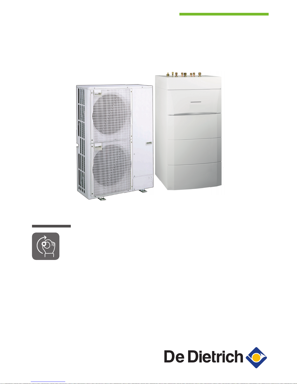
Reversible air/water "Split Inverter" heat pump
ALEZIO S V200
MIV-4S/E 4-8 V200
MIV-4S/E 11-16 V200
MIV-4S/H 4-8 V200
MIV-4S/H 11-16 V200

Dear Customer,
Thank you very much for buying this appliance.
Please read through the manual carefully before using the product, and keep it in a safe place for later reference. In order to
ensure continued safe and efficient operation we recommend that the product is serviced regularly. Our service and customer
service organisation can assist with this.
We hope you enjoy years of problem-free operation with the product.
Contents
1 Safety instructions and recommendations . . . . . . . . . . . . . . . . . . . . . . . . . . . . . . . . . . . . . . . . . . . . . . . . . . . . . . . . . . . . . . . . 5
1.1 Safety . . . . . . . . . . . . . . . . . . . . . . . . . . . . . . . . . . . . . . . . . . . . . . . . . . . . . . . . . . . . . . . . . . . . . . . . . . . . . . . . . . . . . . . 5
1.2 General instructions . . . . . . . . . . . . . . . . . . . . . . . . . . . . . . . . . . . . . . . . . . . . . . . . . . . . . . . . . . . . . . . . . . . . . . . . . . . . 6
1.3 Electrical safety . . . . . . . . . . . . . . . . . . . . . . . . . . . . . . . . . . . . . . . . . . . . . . . . . . . . . . . . . . . . . . . . . . . . . . . . . . . . . . . .6
1.4 Refrigerant safety . . . . . . . . . . . . . . . . . . . . . . . . . . . . . . . . . . . . . . . . . . . . . . . . . . . . . . . . . . . . . . . . . . . . . . . . . . . . . . 7
1.5 Domestic water safety . . . . . . . . . . . . . . . . . . . . . . . . . . . . . . . . . . . . . . . . . . . . . . . . . . . . . . . . . . . . . . . . . . . . . . . . . . .7
1.6 Hydraulic safety . . . . . . . . . . . . . . . . . . . . . . . . . . . . . . . . . . . . . . . . . . . . . . . . . . . . . . . . . . . . . . . . . . . . . . . . . . . . . . . .8
1.7 Recommendations for operation . . . . . . . . . . . . . . . . . . . . . . . . . . . . . . . . . . . . . . . . . . . . . . . . . . . . . . . . . . . . . . . . . . .8
1.8 Specific instructions for service, maintenance and breakdowns . . . . . . . . . . . . . . . . . . . . . . . . . . . . . . . . . . . . . . . . . . .8
1.9 Liabilities . . . . . . . . . . . . . . . . . . . . . . . . . . . . . . . . . . . . . . . . . . . . . . . . . . . . . . . . . . . . . . . . . . . . . . . . . . . . . . . . . . . . . 9
2 Symbols used . . . . . . . . . . . . . . . . . . . . . . . . . . . . . . . . . . . . . . . . . . . . . . . . . . . . . . . . . . . . . . . . . . . . . . . . . . . . . . . . . . . . . 10
2.1 Symbols used in the manual . . . . . . . . . . . . . . . . . . . . . . . . . . . . . . . . . . . . . . . . . . . . . . . . . . . . . . . . . . . . . . . . . . . . .10
2.2 Symbols used on the appliance . . . . . . . . . . . . . . . . . . . . . . . . . . . . . . . . . . . . . . . . . . . . . . . . . . . . . . . . . . . . . . . . . . 10
3 Technical specifications . . . . . . . . . . . . . . . . . . . . . . . . . . . . . . . . . . . . . . . . . . . . . . . . . . . . . . . . . . . . . . . . . . . . . . . . . . . . . 12
3.1 Homologations . . . . . . . . . . . . . . . . . . . . . . . . . . . . . . . . . . . . . . . . . . . . . . . . . . . . . . . . . . . . . . . . . . . . . . . . . . . . . . . 12
3.1.1 Directives . . . . . . . . . . . . . . . . . . . . . . . . . . . . . . . . . . . . . . . . . . . . . . . . . . . . . . . . . . . . . . . . . . . . . . . . . . . .12
3.2 Technical data . . . . . . . . . . . . . . . . . . . . . . . . . . . . . . . . . . . . . . . . . . . . . . . . . . . . . . . . . . . . . . . . . . . . . . . . . . . . . . . .12
3.2.1 Heat pump . . . . . . . . . . . . . . . . . . . . . . . . . . . . . . . . . . . . . . . . . . . . . . . . . . . . . . . . . . . . . . . . . . . . . . . . . . . 12
3.2.2 Domestic hot water tank . . . . . . . . . . . . . . . . . . . . . . . . . . . . . . . . . . . . . . . . . . . . . . . . . . . . . . . . . . . . . . . . 14
3.2.3 Heat pump weight . . . . . . . . . . . . . . . . . . . . . . . . . . . . . . . . . . . . . . . . . . . . . . . . . . . . . . . . . . . . . . . . . . . . . 15
3.2.4 Combination heaters with medium-temperature heat pump . . . . . . . . . . . . . . . . . . . . . . . . . . . . . . . . . . . . . 15
3.2.5 Circulating pump . . . . . . . . . . . . . . . . . . . . . . . . . . . . . . . . . . . . . . . . . . . . . . . . . . . . . . . . . . . . . . . . . . . . . . 19
4 Description of the product . . . . . . . . . . . . . . . . . . . . . . . . . . . . . . . . . . . . . . . . . . . . . . . . . . . . . . . . . . . . . . . . . . . . . . . . . . . . 20
4.1 General description . . . . . . . . . . . . . . . . . . . . . . . . . . . . . . . . . . . . . . . . . . . . . . . . . . . . . . . . . . . . . . . . . . . . . . . . . . . .20
4.2 Operating principle . . . . . . . . . . . . . . . . . . . . . . . . . . . . . . . . . . . . . . . . . . . . . . . . . . . . . . . . . . . . . . . . . . . . . . . . . . . . 20
4.3 Main components . . . . . . . . . . . . . . . . . . . . . . . . . . . . . . . . . . . . . . . . . . . . . . . . . . . . . . . . . . . . . . . . . . . . . . . . . . . . . 21
4.4 Control panel description . . . . . . . . . . . . . . . . . . . . . . . . . . . . . . . . . . . . . . . . . . . . . . . . . . . . . . . . . . . . . . . . . . . . . . . 22
4.4.1 Description of the keys . . . . . . . . . . . . . . . . . . . . . . . . . . . . . . . . . . . . . . . . . . . . . . . . . . . . . . . . . . . . . . . . . 22
4.4.2 Description of the display . . . . . . . . . . . . . . . . . . . . . . . . . . . . . . . . . . . . . . . . . . . . . . . . . . . . . . . . . . . . . . . .22
5 Operation . . . . . . . . . . . . . . . . . . . . . . . . . . . . . . . . . . . . . . . . . . . . . . . . . . . . . . . . . . . . . . . . . . . . . . . . . . . . . . . . . . . . . . . . .25
5.1 Use of the control panel . . . . . . . . . . . . . . . . . . . . . . . . . . . . . . . . . . . . . . . . . . . . . . . . . . . . . . . . . . . . . . . . . . . . . . . . 25
5.1.1 Browsing in the menus . . . . . . . . . . . . . . . . . . . . . . . . . . . . . . . . . . . . . . . . . . . . . . . . . . . . . . . . . . . . . . . . . 25
5.2 Start-up . . . . . . . . . . . . . . . . . . . . . . . . . . . . . . . . . . . . . . . . . . . . . . . . . . . . . . . . . . . . . . . . . . . . . . . . . . . . . . . . . . . . . 25
5.3 Shutdown . . . . . . . . . . . . . . . . . . . . . . . . . . . . . . . . . . . . . . . . . . . . . . . . . . . . . . . . . . . . . . . . . . . . . . . . . . . . . . . . . . . 26
5.3.1 Switching off the heating . . . . . . . . . . . . . . . . . . . . . . . . . . . . . . . . . . . . . . . . . . . . . . . . . . . . . . . . . . . . . . . . 26
5.3.2 Stopping domestic hot water production . . . . . . . . . . . . . . . . . . . . . . . . . . . . . . . . . . . . . . . . . . . . . . . . . . . . 27
5.3.3 Shutting down the cooling function . . . . . . . . . . . . . . . . . . . . . . . . . . . . . . . . . . . . . . . . . . . . . . . . . . . . . . . . 27
5.4 Frost Protection . . . . . . . . . . . . . . . . . . . . . . . . . . . . . . . . . . . . . . . . . . . . . . . . . . . . . . . . . . . . . . . . . . . . . . . . . . . . . . .28
6 Settings . . . . . . . . . . . . . . . . . . . . . . . . . . . . . . . . . . . . . . . . . . . . . . . . . . . . . . . . . . . . . . . . . . . . . . . . . . . . . . . . . . . . . . . . . . 29
6.1 Modifying the User parameters . . . . . . . . . . . . . . . . . . . . . . . . . . . . . . . . . . . . . . . . . . . . . . . . . . . . . . . . . . . . . . . . . 29
6.2 User menu . . . . . . . . . . . . . . . . . . . . . . . . . . . . . . . . . . . . . . . . . . . . . . . . . . . . . . . . . . . . . . . . . . . . . . . . . . . . . . . . . 29
6.2.1 CIRCA / CIRCB sub-menus in the User menu . . . . . . . . . . . . . . . . . . . . . . . . . . . . . . . . . . . . . . . . . . . . . .29
6.2.2 ECS sub-menu in the User menu . . . . . . . . . . . . . . . . . . . . . . . . . . . . . . . . . . . . . . . . . . . . . . . . . . . . . . . .31
6.2.3 EHC-04 sub-menu of the User menu . . . . . . . . . . . . . . . . . . . . . . . . . . . . . . . . . . . . . . . . . . . . . . . . . . . . . 31
6.2.4 HMI sub-menu in the User menu . . . . . . . . . . . . . . . . . . . . . . . . . . . . . . . . . . . . . . . . . . . . . . . . . . . . . . . . 32
6.2.5 HP parameters in the User menu . . . . . . . . . . . . . . . . . . . . . . . . . . . . . . . . . . . . . . . . . . . . . . . . . . . . . . . .32
6.3 COUNTERS /TIME PROG / CLOCK menus . . . . . . . . . . . . . . . . . . . . . . . . . . . . . . . . . . . . . . . . . . . . . . . . . . . . . . 33
6.3.1 CNT sub-menu . . . . . . . . . . . . . . . . . . . . . . . . . . . . . . . . . . . . . . . . . . . . . . . . . . . . . . . . . . . . . . . . . . . . . 33
6.4 Setting the parameters . . . . . . . . . . . . . . . . . . . . . . . . . . . . . . . . . . . . . . . . . . . . . . . . . . . . . . . . . . . . . . . . . . . . . . . . . 35
6.4.1 Setting the room temperature set point in comfort mode . . . . . . . . . . . . . . . . . . . . . . . . . . . . . . . . . . . . . . . .35
6.4.2 Setting the domestic hot water temperature . . . . . . . . . . . . . . . . . . . . . . . . . . . . . . . . . . . . . . . . . . . . . . 35
6.4.3 Activating Forcing of the cooling function . . . . . . . . . . . . . . . . . . . . . . . . . . . . . . . . . . . . . . . . . . . . . . . . . . . 35
6.4.4 Activating Manual Forcing for heating . . . . . . . . . . . . . . . . . . . . . . . . . . . . . . . . . . . . . . . . . . . . . . . . . . . . 36
6.4.5 Setting the timer programming . . . . . . . . . . . . . . . . . . . . . . . . . . . . . . . . . . . . . . . . . . . . . . . . . . . . . . . . . 37
7 Reading out measured values . . . . . . . . . . . . . . . . . . . . . . . . . . . . . . . . . . . . . . . . . . . . . . . . . . . . . . . . . . . . . . . . . . . . . . 39
7.1 Control system sequence . . . . . . . . . . . . . . . . . . . . . . . . . . . . . . . . . . . . . . . . . . . . . . . . . . . . . . . . . . . . . . . . . . . . . . . 40
Contents
7682850 - v02 - 09012018 MIV-4S 3

8 Maintenance . . . . . . . . . . . . . . . . . . . . . . . . . . . . . . . . . . . . . . . . . . . . . . . . . . . . . . . . . . . . . . . . . . . . . . . . . . . . . . . . . . . . . . 45
8.1 General . . . . . . . . . . . . . . . . . . . . . . . . . . . . . . . . . . . . . . . . . . . . . . . . . . . . . . . . . . . . . . . . . . . . . . . . . . . . . . . . . . . . . 45
8.2 Cleaning the casing . . . . . . . . . . . . . . . . . . . . . . . . . . . . . . . . . . . . . . . . . . . . . . . . . . . . . . . . . . . . . . . . . . . . . . . . . . . 45
8.3 Standard inspection and maintenance operations . . . . . . . . . . . . . . . . . . . . . . . . . . . . . . . . . . . . . . . . . . . . . . . . . . . . 45
9 Troubleshooting . . . . . . . . . . . . . . . . . . . . . . . . . . . . . . . . . . . . . . . . . . . . . . . . . . . . . . . . . . . . . . . . . . . . . . . . . . . . . . . . . . . .46
9.1 Error messages . . . . . . . . . . . . . . . . . . . . . . . . . . . . . . . . . . . . . . . . . . . . . . . . . . . . . . . . . . . . . . . . . . . . . . . . . . . . . . .46
9.1.1 Error codes . . . . . . . . . . . . . . . . . . . . . . . . . . . . . . . . . . . . . . . . . . . . . . . . . . . . . . . . . . . . . . . . . . . . . . . . . . 46
9.1.2 Fault codes . . . . . . . . . . . . . . . . . . . . . . . . . . . . . . . . . . . . . . . . . . . . . . . . . . . . . . . . . . . . . . . . . . . . . . . . . . 47
9.1.3 Alarm codes . . . . . . . . . . . . . . . . . . . . . . . . . . . . . . . . . . . . . . . . . . . . . . . . . . . . . . . . . . . . . . . . . . . . . . . . . .47
9.2 Accessing the error memory . . . . . . . . . . . . . . . . . . . . . . . . . . . . . . . . . . . . . . . . . . . . . . . . . . . . . . . . . . . . . . . . . . 48
9.3 Troubleshooting . . . . . . . . . . . . . . . . . . . . . . . . . . . . . . . . . . . . . . . . . . . . . . . . . . . . . . . . . . . . . . . . . . . . . . . . . . . . . . 48
10 Decommissioning and disposal . . . . . . . . . . . . . . . . . . . . . . . . . . . . . . . . . . . . . . . . . . . . . . . . . . . . . . . . . . . . . . . . . . . . . . . .50
10.1 Decommissioning procedure . . . . . . . . . . . . . . . . . . . . . . . . . . . . . . . . . . . . . . . . . . . . . . . . . . . . . . . . . . . . . . . . . . . . .50
10.2 Disposal and Recycling . . . . . . . . . . . . . . . . . . . . . . . . . . . . . . . . . . . . . . . . . . . . . . . . . . . . . . . . . . . . . . . . . . . . . . . . .50
11 Environmental . . . . . . . . . . . . . . . . . . . . . . . . . . . . . . . . . . . . . . . . . . . . . . . . . . . . . . . . . . . . . . . . . . . . . . . . . . . . . . . . . . . . . 51
11.1 Energy savings . . . . . . . . . . . . . . . . . . . . . . . . . . . . . . . . . . . . . . . . . . . . . . . . . . . . . . . . . . . . . . . . . . . . . . . . . . . . . . . 51
12 Warranty . . . . . . . . . . . . . . . . . . . . . . . . . . . . . . . . . . . . . . . . . . . . . . . . . . . . . . . . . . . . . . . . . . . . . . . . . . . . . . . . . . . . . . . . . 52
12.1 General . . . . . . . . . . . . . . . . . . . . . . . . . . . . . . . . . . . . . . . . . . . . . . . . . . . . . . . . . . . . . . . . . . . . . . . . . . . . . . . . . . . . . 52
12.2 Terms of warranty . . . . . . . . . . . . . . . . . . . . . . . . . . . . . . . . . . . . . . . . . . . . . . . . . . . . . . . . . . . . . . . . . . . . . . . . . . . . . 52
13 Appendix . . . . . . . . . . . . . . . . . . . . . . . . . . . . . . . . . . . . . . . . . . . . . . . . . . . . . . . . . . . . . . . . . . . . . . . . . . . . . . . . . . . . . . . . . 53
13.1 Product fiche . . . . . . . . . . . . . . . . . . . . . . . . . . . . . . . . . . . . . . . . . . . . . . . . . . . . . . . . . . . . . . . . . . . . . . . . . . . . . . . . . 53
13.2 Product fiche - Temperature Controls . . . . . . . . . . . . . . . . . . . . . . . . . . . . . . . . . . . . . . . . . . . . . . . . . . . . . . . . . . . . . .54
13.3 Package fiche . . . . . . . . . . . . . . . . . . . . . . . . . . . . . . . . . . . . . . . . . . . . . . . . . . . . . . . . . . . . . . . . . . . . . . . . . . . . . . . . 54
13.4 Package fiche - Combination heaters (boilers or heat pumps) . . . . . . . . . . . . . . . . . . . . . . . . . . . . . . . . . . . . . . . . . . . 57
Contents
4 MIV-4S 7682850 - v02 - 09012018
1 Safety instructions and recommendations
1.1 Safety
Operation
Danger
This appliance can be used by children aged from 8 years
and above and persons with reduced physical, sensory or
mental capabilities or lack of experience and knowledge if
they have been given supervision or instruction concerning
use of the appliance in a safe way and understand the haz
ards involved. Children shall not play with the appliance.
Cleaning and user maintenance shall not be made by children
without supervision.
Electrical
The appliance is intended to be permanently connected to the domestic water
mains network.
Before any work on the appliance, carefully read all documents that accompa
ny the product. These documents are also available on our website: www.dedi
etrich-thermique.com
Install the appliance in accordance with national rules on electrical installation.
A disconnection device must be fitted to the permanent pipes in accordance
with installation rules.
If a power supply cable comes with the appliance and it turns out to be dam
aged, it must be replaced by the manufacturer, its after sales service or per
sons with similar qualifications in order to obviate any danger.
If the appliance is not wired in the factory, carry out the wiring according to the
wiring schematics described in the chapter Electrical Connections (Installation
and Service Manual).
This appliance must be connected to the protective earth.
Earthing must comply with the prevailing installation standards.
Earth the appliance before making any electrical connections.
Type and calibre of the protective equipment: refer to the chapter Recommen
ded cable cross-sections. See the Installation and Service Manual.
To connect the appliance to the mains supply, refer to the chapter Electrical
Connections in the appliance's installation and service manual.
In order to prevent any danger owing to the unexpected reset of the thermal
circuit breaker, this appliance must not be powered through an external switch,
such as a timer, or be connected to a circuit which is regularly switched on and
off by the electricity provider.
1 Safety instructions and recommendations
7682850 - v02 - 09012018 MIV-4S 5
Domestic wa
ter
Draining the appliance:
1. Shut off the domestic cold water inlet.
2. Open a hot water tap in the installation.
3. Open a valve on the safety unit.
4. When the water stops flowing, the appliance has been drained.
The pressure limiter device (safety valve or safety unit) must be regularly oper
ated in order to remove limescale deposits and ensure that it is not blocked.
A pressure limiter device must be fitted to a discharge pipe.
As water may flow out of the discharge pipe, the pipe must be kept open to the
open air, in a frost-free environment, and at a continuous downward gradient.
To ascertain the type or specifications of the pressure limiter and to find out
how to connect it, refer to the chapter, "Connecting the domestic hot water tank
to the drinking water mains".
Hydraulics
Caution
Respect the minimum and maximum water pressure and tem
perature to ensure the appliance operates correctly. See
chapter on Technical Specifications
Installation
Important
Allow the space required to install the appliance correctly, re
ferring to the chapter Dimensions of the Appliance. See the
Installation and Service Manual.
1.2
General instructions
The system must satisfy each point in the rules in force in the country that
govern works and interventions in individual homes, blocks of flats or other
buildings.
Only qualified professionals are authorised to work on the appliance and
the heating installation. They must respect prevailing local and national
regulations during fitting, installation and maintenance of the installation.
Commissioning must be performed by a qualified professional.
1.3 Electrical safety
Before making any electrical connections, earth the appliance in accord
ance with prevailing standards.
Danger of electric shock: the length of the conductors between the traction
arrester device and the terminal blocks must be such that the active con
ductors are put under tension before the earth conductor.
Only qualified professionals may carry out electrical connections, always
with the power off.
Separate the very low voltage cables from the 230/400 V circuit cables.
1 Safety instructions and recommendations
6 MIV-4S 7682850 - v02 - 09012018

1.4 Refrigerant safety
Warning
Refrigerant fluid and pipes:
Use only R410A refrigerant fluid to fill the installation.
Use tools and pipe components especially designed for use with
R410A refrigerant fluid.
Use copper pipes deoxidised with phosphorus to carry the re
frigerant fluid.
Store the refrigerant connection pipes away from dust and hu
midity (risk of damage to the compressor).
Do not use a load cylinder.
Protect the heat pump components, including the insulation and
structural elements. Do not overheat the pipes as brazed com
ponents may cause damage.
Contact between the refrigerant fluid and a flame may result in
emissions of toxic gases.
France: Pursuant to Article L. 113-3 of the French Consumer Code, the in
stallation of equipment must be done by a certified operator whenever the
refrigerant load is in excess of two kilograms or when a refrigerant connec
tion is necessary (the case with split systems, even when fitted with a
quick coupling device).
All work on the refrigeration circuit must be done by a qualified professio
nal, according to prevailing codes of practice and safety in the profession
(recovery of the refrigerant, brazing under nitrogen). All brazing work must
be done by qualified welders.
Do not touch the refrigeration connection pipes with your bare hands while
the heat pump is running. Danger of burn or frost injury.
In the event of a refrigerant leakage:
1. Switch off the appliance.
2. Open the windows.
3. Do not use a naked flame, do not smoke, do not operate electrical
contacts.
4. Avoid contact with the refrigerant. Danger of frost injuries.
Locate the probable leak and seal it immediately. Use only original parts to
replace a defective refrigeration component.
Use only dehydrated nitrogen for detecting leaks or for pressurised tests.
Do not allow the refrigerant fluid to escape into the atmosphere.
1.5 Domestic water safety
In accordance with safety rules, a safety valve calibrated to 0.7 MPa (7
bar) is mounted on the tank's domestic cold water inlet.
A pressure reducer (not provided) is required when the supply pressure
exceeds 80% of the safety valve or safety unit calibration and must be lo
cated upstream of the appliance.
There must be no cut-off devices between the safety valve or unit and the
domestic hot water tank.
The hydraulic installation must be capable of handling a minimum flow rate
at all times.
Heating water and domestic water must not come into contact with each
other. Domestic water must not circulate through the exchanger.
Limit temperature at the draw-off point: the maximum domestic hot water
temperature at the draw-off point is subject to special regulations in the
various countries in which the appliance is sold in order to protect the
user. These special regulations be observed when installing the appliance.
Take precautions with the domestic hot water. Depending on the heat
pump settings, the domestic hot water temperature may exceed 65°C.
1 Safety instructions and recommendations
7682850 - v02 - 09012018 MIV-4S 7

In order to limit the risk of being scalded, a thermostatic mixing valve must
be installed on the domestic hot water flow pipes.
1.6 Hydraulic safety
When making the hydraulic connection, it is imperative that the standards
and corresponding local directives be respected.
If radiators are connected directly to the heating circuit: install a differential
valve between the indoor module and the heating circuit.
Keep a heating circuit without thermostatic valve and or without solenoid
valve in order to avoid having all valves closed at the same time.
Fit drainage valves between the indoor module and the heating circuit.
Do not add any chemical products to the heating water without first con
sulting a water treatment specialist. For example: antifreeze, water soften
ers, products to increase or reduce the pH value, chemical additives
and/or inhibitors. These may cause faults in the heat pump and damage
the heat exchanger.
1.7
Recommendations for operation
The frost protection function does not work if the heat pump is switched
off.
If the home is unoccupied for a long period and there is a risk of frost,
drain the indoor module and the heating system.
Keep the heat pump accessible at all times.
Never remove or cover the labels and data plates affixed to appliances.
Labels and data plates must be legible throughout the entire lifetime of the
appliance.
Immediately replace damaged or illegible instructions and warning stick
ers.
Give preference to the OFF or frost protection mode rather than switching
off the system to leave the following functions running:
Anti blocking of pumps
Frost Protection
Regularly check the presence of water and pressure in the heating sys
tem.
Do not touch radiators for long periods. Depending on the heat pump set
tings, the temperature of the radiators may exceed 60°C.
Do not drain the installation, except in cases of absolute necessity. E.g.:
several months' absence with the risk of temperatures in the building fall
ing below freezing.
1.8
Specific instructions for service, maintenance and breakdowns
Maintenance work must be carried out by a qualified professional.
Only a qualified professional is authorised to set, correct or replace the
safety devices.
Before any work, switch off the mains electricity to the heat pump, the in
door unit and the hydraulic or electrical back-up if connected.
Wait for approx. 20-30 seconds for the outdoor unit capacitors to be dis
charged, and check that the lights on the outdoor unit PCBs have gone
out.
Before working on the refrigeration circuit, switch off the appliance and
wait a few minutes. Certain items of equipment such as the compressor
and the pipes can reach temperatures in excess of 100 °C and high pres
sures, which may cause serious injuries.
Locate and correct the cause of power cut before resetting the safety ther
mostat.
1 Safety instructions and recommendations
8 MIV-4S 7682850 - v02 - 09012018
Only genuine spare parts may be used.
Removal and disposal of the heat pump must be carried out by a qualified
professional in accordance with prevailing local and national regulations.
Do not allow the refrigerant fluid to escape into the atmosphere.
After maintenance or repair work, check the entire heating system to en
sure that there are no leaks.
Remove the casing only to perform maintenance and repair work. Put the
casing back in place after maintenance and repair work.
1.9 Liabilities
Manufacturer's liability Our products are manufactured in compliance with the requirements of the various Directives appli
cable. They are therefore delivered with the marking and any documents necessary. In the inter
ests of the quality of our products, we strive constantly to improve them. We therefore reserve the
right to modify the specifications given in this document.
Our liability as manufacturer may not be invoked in the following cases:
Failure to abide by the instructions on installing the appliance.
Failure to abide by the instructions on using the appliance.
Faulty or insufficient maintenance of the appliance.
Installer's liability The installer is responsible for the installation and initial commissioning of the appliance. The instal
ler must observe the following instructions:
Read and follow the instructions given in the manuals provided with the appliance.
Install the appliance in compliance with prevailing legislation and standards.
Carry out initial commissioning and any checks necessary.
Explain the installation to the user.
If maintenance is necessary, warn the user of the obligation to check the appliance and keep it in
good working order.
Give all the instruction manuals to the user.
User's liability To guarantee optimum operation of the system, you must abide by the following instructions:
Read and follow the instructions given in the manuals provided with the appliance.
Call on a qualified professional to carry out installation and initial commissioning.
Get your installer to explain your installation to you.
Have the required inspections and maintenance carried out by a qualified installer.
Keep the instruction manuals in good condition close to the appliance.
1 Safety instructions and recommendations
7682850 - v02 - 09012018 MIV-4S 9

2 Symbols used
2.1 Symbols used in the manual
This manual uses various danger levels to draw attention to special in
structions. We do this to improve user safety, to prevent problems and to
guarantee correct operation of the appliance.
Danger
Risk of dangerous situations that may result in serious personal
injury.
Danger of electric shock
Risk of electric shock.
Warning
Risk of dangerous situations that may result in minor personal in
jury.
Caution
Risk of material damage.
Important
Please note: important information.
See
Reference to other manuals or pages in this manual.
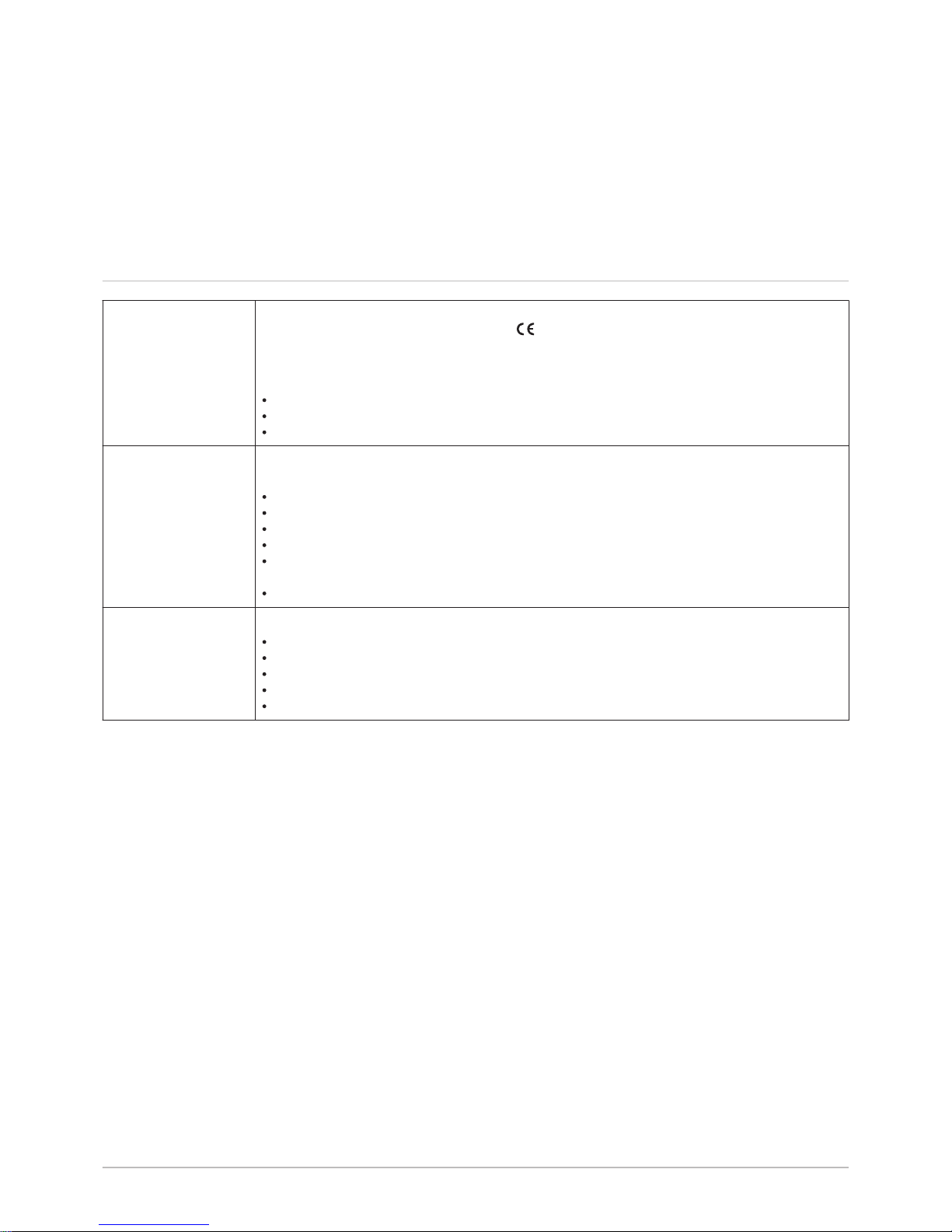
2.2 Symbols used on the appliance
1 Alternating current
2 Protective earthing
1 Information on the heat pump: type of refrigerant fluid, maximum
operating pressure and output absorbed by the indoor module
2 Information on the domestic hot water tank: volume, maximum op
erating pressure and standby losses of the domestic hot water tank
3 Information on the electrical back-up: power supply and maximum
output (only for versions with electrical back-up)
4 Before installing and commissioning the appliance, carefully read
the instruction manuals provided
5 Dispose of used products in an appropriate recovery and recycling
structure
6 The symbol indicates compatibility with SMART TC.
Fig.1 Symbols used on the appliance
MW-6000066-3
1 2
Fig.2 Symbols used on the data plate
MW-3000555-02
1
2
4 65
3
2 Symbols used
10 MIV-4S 7682850 - v02 - 09012018
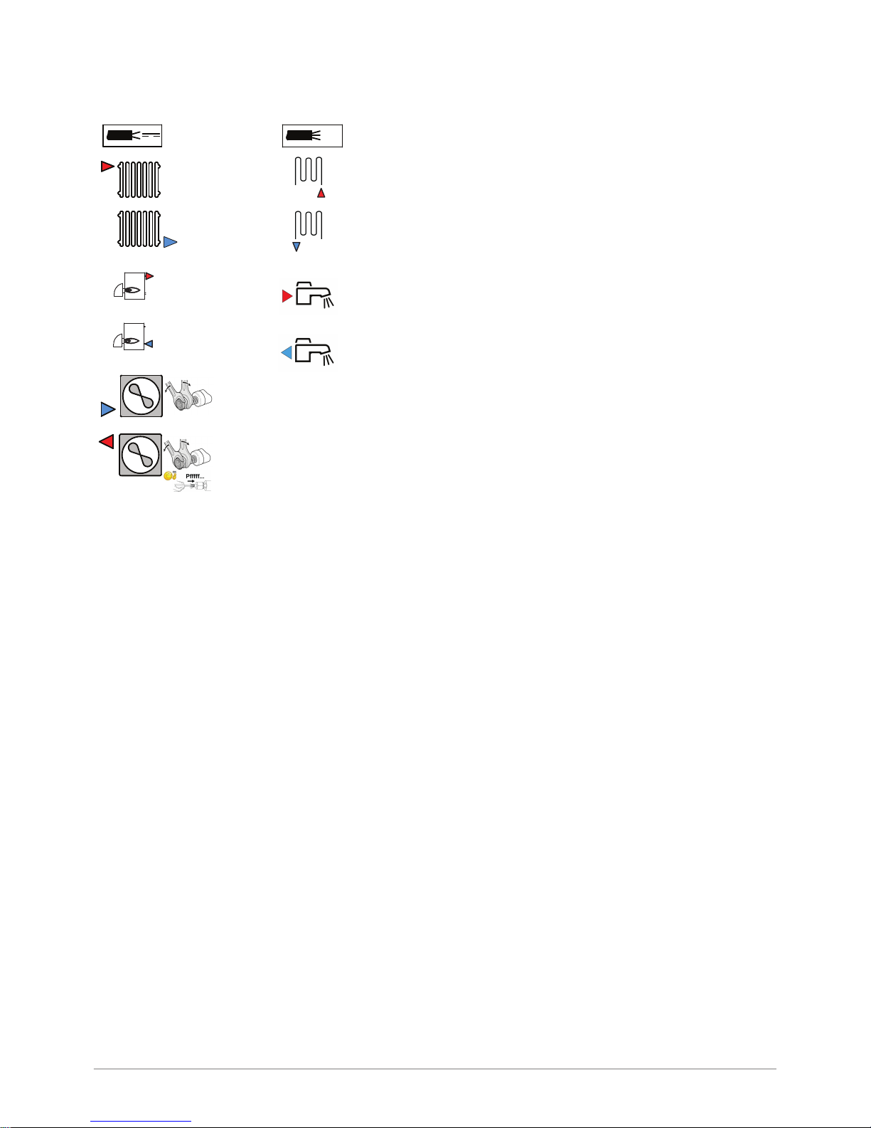
1 Sensor cable - low voltage
2 Power supply cable 230 V / 400 V
3 Heating circuit flow
4 Circuit B flow
5 Heating circuit return
6 Circuit B return (optional)
7 Connection for recirculation
8 Domestic hot water outlet
9 Flow to boiler back-up
10 Return from boiler back-up
11 Domestic cold water inlet
12 Drain valve
13 Safety valve
14 3/8" refrigerant fluid connection – liquid line
15 5/8" refrigerant fluid connection – gas line
Fig.3 Symbols used on the connection la
bel
MW-3000554-02
A
G1"
A
G1"
G3/4"
G3/4"
5/8"
69-82 Nm
3/8"
34-42 Nm
1
2
4
6
8
3
5
7
9
11
12
B
G1"
B
G1"
G3/4"
G3/4"
10
2 Symbols used
7682850 - v02 - 09012018 MIV-4S 11
3 Technical specifications
3.1 Homologations
3.1.1 Directives
This product complies with the requirements of the following European Di
rectives and Standards:
Pressure Equipment Directive 2014/68/EU
Low Voltage Directive 2014/35/EU
Generic standard: EN 60335-1
Relevant standards: EN 60335-2-21, EN 60335-2-40
Electromagnetic Compatibility Directive 2014/30/EU
Generic standards: EN 61000-6-3, EN 61000-6-1
Relevant Standard: EN 55014
This product conforms to the requirements of European Directive
2009/125/EC on the ecodesign of energy-related products.
In addition to the legal requirements and guidelines, the supplementary
guidelines in this manual must also be followed.
Supplements or subsequent regulations and guidelines that are valid at
the time of installation shall apply to all regulations and guidelines speci
fied in this manual.
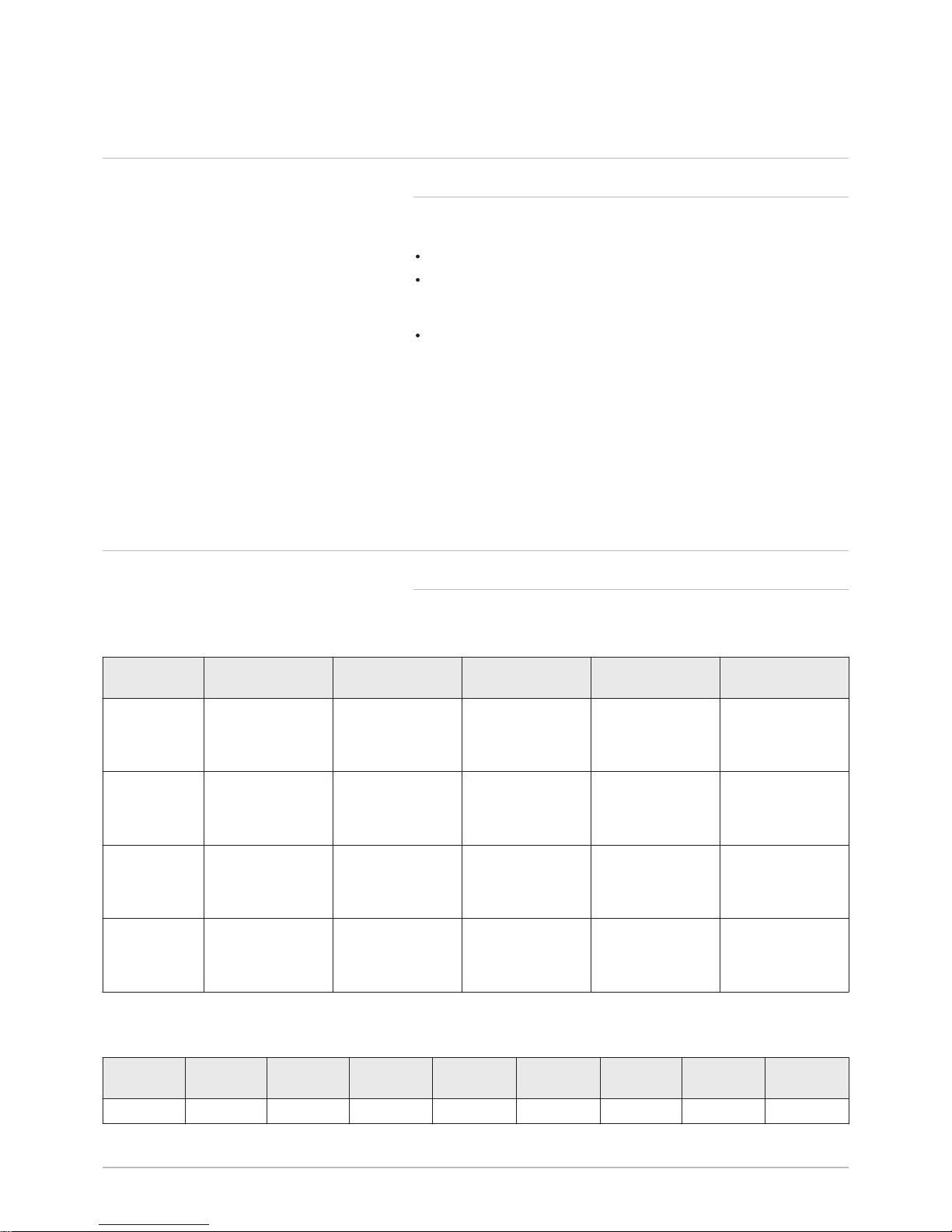
3.2 Technical data
3.2.1 Heat pump
Maximum operating pressure: 0.3 MPa (3 bar)
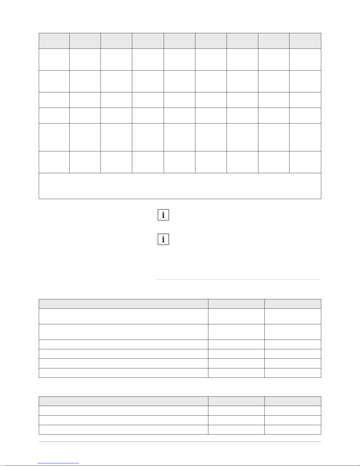
Tab.1 Conditions of use
AWHP 4.5 MR AWHP 6 MR-3 AWHP 8 MR-2 AWHP 11 MR-2
AWHP 11 TR-2
AWHP 16 MR-2
AWHP 16 TR-2
Limit water op
erating temper
atures in heat
ing mode
+18 °C/+55 °C +18 °C/+60 °C +18 °C/+60 °C +18 °C/+60 °C +18 °C/+60 °C
Limit outdoor
air operating
temperatures in
heating mode
-15° C/+35 °C -15° C/+35 °C -20° C/+35 °C -20° C/+35 °C -20° C/+35 °C
Limit water op
erating temper
atures in cool
ing mode
+7 °C/+25 °C +7 °C/+25 °C +7 °C/+25 °C +7 °C/+25 °C +7 °C/+25 °C
Limit outdoor
air operating
temperatures in
cooling mode
+7 °C/+40 °C +7 °C/+40 °C +7 °C/+40 °C +7 °C/+40 °C +7 °C/+40 °C
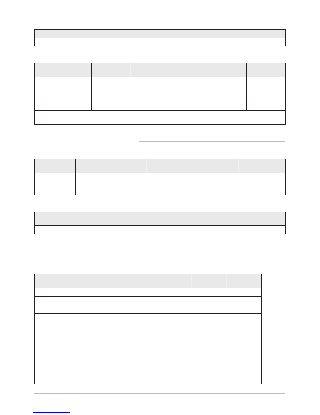
Tab.2 Heating mode: outside air temperature +7°C, water temperature at the outlet +35°C. Performances in accordance with
EN 14511-2.
Measure
ment type
Unit AWHP 4.5 MRAWHP 6
MR-3
AWHP 8
MR-2
AWHP 11
MR-2
AWHP 11
TR-2
AWHP 16
MR-2
AWHP 16
TR-2
Heat output kW 4.60 5.82 7.9 11.39 11.39 14.65 14.65
3 Technical specifications
12 MIV-4S 7682850 - v02 - 09012018
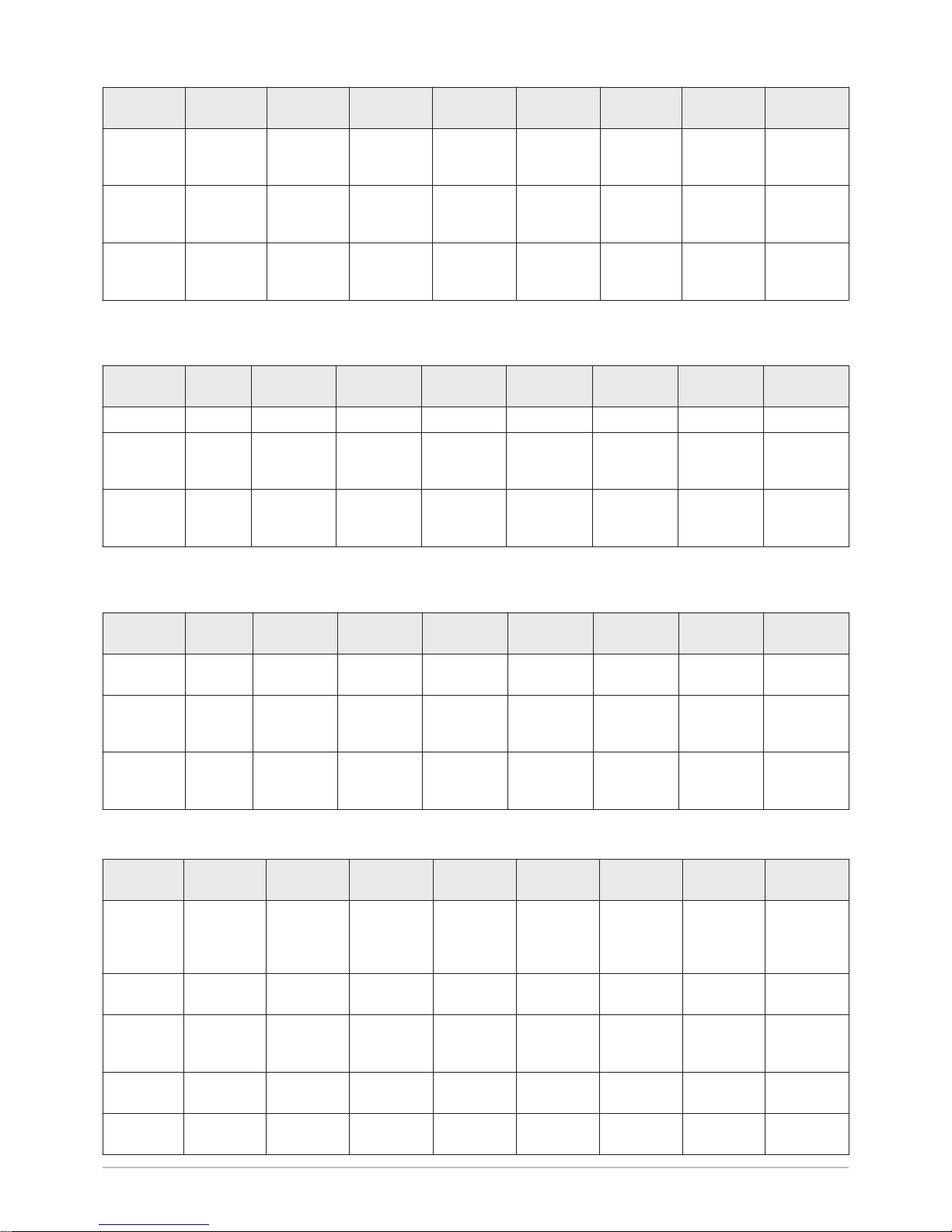
Measure
ment type
Unit AWHP 4.5 MRAWHP 6
MR-3
AWHP 8
MR-2
AWHP 11
MR-2
AWHP 11
TR-2
AWHP 16
MR-2
AWHP 16
TR-2
Coefficient
of Perform
ance (COP)
5.11 4.22 4.34 4.65 4.65 4.22 4.22
Absorbed
electrical
power
kWe 0.90 1.38 1.82 2.45 2.45 3.47 3.47
Nominal wa
ter flow rate
(ΔT = 5K)
m3/hour
0.80 1.00 1.36 1.96 1.96 2.53 2.53
Tab.3 Heating mode: outside air temperature +2°C, water temperature at the outlet +35°C. Performances in accordance with
EN 14511-2.
Measure
ment type
Unit AWHP 4.5 MRAWHP 6
MR-3
AWHP 8
MR-2
AWHP 11
MR-2
AWHP 11
TR-2
AWHP 16
MR-2
AWHP 16
TR-2
Heat output kW 3.47 3.74 6.80 10.19 10.19 12.90 12.90
Coefficient
of Perform
ance (COP)
3.97 3.37 3.30 3.20 3.20 3.27 3.27
Absorbed
electrical
power
kWe 0.90 1.38 2.06 3.19 3.19 3.94 3.94
Tab.4 Cooling mode: outside air temperature +35°C, water temperature at the outlet +18°C. Performances in accordance
with EN 14511-2.
Measure
ment type
Unit AWHP 4.5 MRAWHP 6
MR-3
AWHP 8
MR-2
AWHP 11
MR-2
AWHP 11
TR-2
AWHP 16
MR-2
AWHP 16
TR-2
Cooling out
put
kW 3.80 4.69 7.90 11.16 11.16 14.46 14.46
Energy effi
ciency ratio
(EER)
4.28 4.09 3.99 4.75 4.75 3.96 3.96
Absorbed
electrical
power
kWe 0.89 1.15 2.00 2.35 2.35 3.65 3.65
Tab.5 Common specifications
Measure
ment type
Unit AWHP 4.5 MRAWHP 6
MR-3
AWHP 8
MR-2
AWHP 11
MR-2
AWHP 11
TR-2
AWHP 16
MR-2
AWHP 16
TR-2
Total dy
namic head
at nominal
flow rate
kPa 65 63 44 25 25 — —
Nominal air
flow rate
m3/h
2650 2700 3300 6000 6000 6000 6000
Power volt
age of the
outdoor unit
V 230 230 230 230 400 230 400
Start-up
amperage
A 5 5 5 5 3 6 3
Maximal
amperage
A 12 13 19 29.5 13 29.5 13
3 Technical specifications
7682850 - v02 - 09012018 MIV-4S 13
Measure
ment type
Unit AWHP 4.5 MRAWHP 6
MR-3
AWHP 8
MR-2
AWHP 11
MR-2
AWHP 11
TR-2
AWHP 16
MR-2
AWHP 16
TR-2
Acoustic
power - In
side
(1)
dB(A) 48.8 48.8 48.8 47.6 47.6 47.6 47.6
Acoustic
power Outside
(2)
dB(A) 61.0 64.8 66.7 69.2 69.2 69.7 69.7
Refrigerant
fluid R410A
kg 1.3 1.4 3.2 4.6 4.6 4.6 4.6
R410A re
frigerant
(3)
tCO2e 2.714 2.923 6.680 9.603 9.603 9.603 9.603
Refrigerant
connection
(Liquid Gas)
inch 1/4 - 1/2 1/4 - 1/2 3/8 - 5/8 3/8 - 5/8 3/8 - 5/8 3/8 - 5/8 3/8 - 5/8
Max. precharged
length
m 7 10 10 10 10 10 10
(1) Noise radiated by the envelope - Test run in accordance with the NF EN 12102 standard, temperature conditions: air 7°C, water 55°C
(2) Noise radiated by the envelope - Test run in accordance with the NF EN 12102 standard, temperature conditions: air 7 °C, water 45 °C
for AWHP 4.5 MR only (inner and outer sides).
(3) Quantity of refrigerant calculated in tonnes of CO2 equivalent
Important
R410A refrigerant fluid is contained in equipment that has been
hermetically sealed.
Important
The Global-Warming Potential (GWP) of R410A gas is 2088.
The values in tonnes of CO2 equivalent are calculated using the
following formula: quantity (in kg) of refrigerant fluid x GWP /
1000.
3.2.2
Domestic hot water tank
Tab.6 Technical specifications primary circuit (heating water)
Specification Unit Value
Maximum operating temperature
Version with hydraulic back-up
°C 90
Maximum operating temperature
Version with electrical back-up
°C 75
Minimum operating temperature °C 7
Maximum operating pressure MPa (bar) 0.3 (3.0)
Domestic hot water tank exchanger capacity Litres 11.3
Exchange surface m² 1.7
Tab.7 Technical specifications secondary circuit (domestic water)
Specification Unit Value
Maximum operating temperature °C 80
Minimum operating temperature °C 10
Maximum operating pressure MPa (bar) 1.0 (10.0)
3 Technical specifications
14 MIV-4S 7682850 - v02 - 09012018
Specification Unit Value
Water capacity Litres 177
Tab.8 Common specifications (in accordance with the EN 16147 standard)
AWHP 4.5 MR AWHP 6 MR-3 AWHP 8 MR-2 AWHP 11 MR-2
AWHP 11 TR-2
AWHP 16 MR-2
AWHP 16 TR-2
Loading time
(1)
1 hour 40 minutes 2 hours 2 hours 11 mi
nutes
1 hour 33 minutes 1 hour 11 minutes
Coefficient of performance
domestic hot water
(COP
DHW
)
3.00 2.72 2.72 2.72 2.72
(1) Water temperature set point: 53°C (except for AWHP 4.5 MR: 54°C) – Outside temperature: 7°C – Inside air temperature:
20°C
3.2.3 Heat pump weight
Tab.9 Indoor module
Indoor module Unit MIV-4S/E 4-8 V200 MIV-4S/H 4-8 V200 MIV-4S/E 11-16
V200
MIV-4S/H 11-16 V200
Weight (empty) kg 138 137 140 139
Total weight with
water
kg 333 332 335 334
Tab.10 Outdoor unit
Outdoor unit Unit AWHP 4.5 MR AWHP 6 MR-3 AWHP 8 MR-2 AWHP 11 MR-2
AWHP 16 MR-2
AWHP 11 TR-2
AWHP 16 TR-2
Weight (empty) kg 54 42 75 118 130
3.2.4 Combination heaters with medium-temperature heat
pump
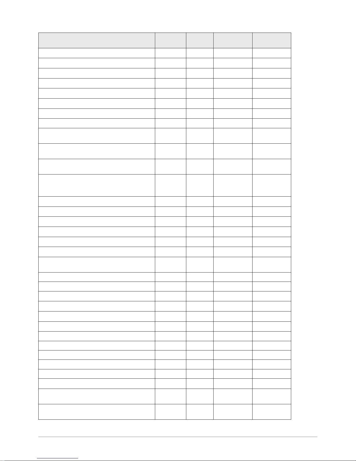
Tab.11 Technical parameters for heat pump combination heaters (parameters declared for medium-temperature application)
Product name MIV-4S
AWHP 4.5 MR
MIV-4S
AWHP 6 MR-3
Air-to-water heat pump Yes Yes
Water-to-water heat pump No No
Brine-to-water heat pump No No
Low-temperature heat pump No No
Equipped with a supplementary heater Yes Yes
Heat pump combination heater Yes Yes
Rated heat output under average conditions
(1)
Prated
kW 4 4
Rated heat output under colder conditions
Prated
kW 5 4
Rated heat output under warmer conditions
Prated
kW 4 5
Declared capacity for heating for part load at an in
door temperature of 20°C and outdoor temperature
T
j
3 Technical specifications
7682850 - v02 - 09012018 MIV-4S 15
Product name MIV-4S
AWHP 4.5 MR
MIV-4S
AWHP 6 MR-3
T
j
= -7°C
Pdh
kW 3.8 3.5
T
j
= +2°C
Pdh
kW 4.3 4.5
T
j
= +7°C
Pdh
kW 4.5 4.8
T
j
= +12°C
Pdh
kW 5.5 5.2
T
j
= bivalent temperature
Pdh
kW 3.9 3.6
T
j
= operation limit temperature
Pdh
kW 3.9 3.6
Bivalent temperature
T
biv
°C -10 -10
Degradation coefficient
(2)
Cdh
— 1.0 1.0
Seasonal space heating energy efficiency under
average conditions
ƞ
s
% 134 137
Seasonal space heating energy efficiency under
colder conditions
ƞ
s
% 109 116
Seasonal space heating energy efficiency under
warmer conditions
ƞ
s
% 179 172
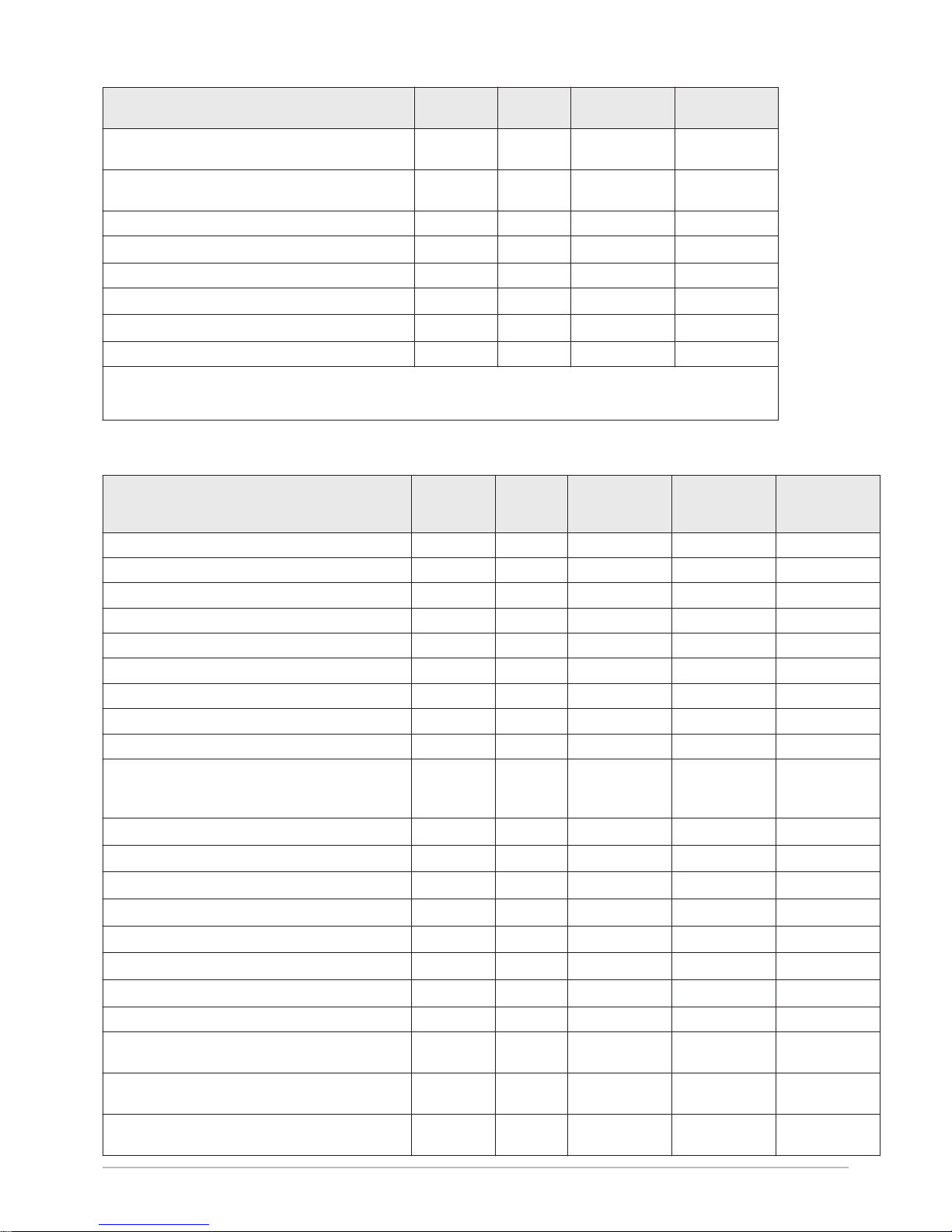
Declared coefficient of performance or primary en
ergy ratio for part load at an indoor temperature of
20°C and outdoor temperature
T
j
T
j
= -7°C
COPd
- 1.64 1.89
T
j
= +2°C
COPd
- 3.46 3.53
T
j
= +7°C
COPd
- 4.96 4.74
T
j
= +12°C
COPd
- 7.90 7.08
T
j
= bivalent temperature
COPd
- 1.20 1.52
T
j
= operation limit temperature
COPd
- 1.20 1.52
Operation limit temperature for air-to-water heat
pumps
TOL
°C -10 -10
Heating water operating limit temperature
WTOL
°C 55 60
Electrical power consumption
Off mode
P
OFF
kW 0.009 0.009
Thermostat-off mode
P
TO
kW 0.049 0.049
Stand-by
P
SB
kW 0.009 0.015
Crankcase heater mode
P
CK
kW 0.000 0.055
Supplementary heater
Rated heat output
Psup
kW 0.0 0.0
Type of energy input Electricity Electricity
Other specifications
Capacity control Variable Variable
Sound power level, indoors - outdoors
L
WA
dB 49 – 61 49 – 62
Annual energy consumption under average con
ditions
Q
HE
kWh 2353 2124
Annual energy consumption under colder condi
tions
Q
HE
kWh 4483 3721
3 Technical specifications
16 MIV-4S 7682850 - v02 - 09012018
Product name MIV-4S
AWHP 4.5 MR
MIV-4S
AWHP 6 MR-3
Annual energy consumption under warmer condi
tions
Q
HE
kWh 1249 1492
Rated air flow rate, outdoors for air-to-water heat
pumps
—
m3/h
2100 2100
Declared load profile L L
Daily electricity consumption
Q
elec
kWh 4.020 4.816
Annual electricity consumption
AEC
kWh 845 968
Water heating energy efficiency
ƞ
wh
% 121.00 106.00
Daily fuel consumption
Q
fuel
kWh 0.000 0.000
Annual fuel consumption
AFC
GJ 0 0
(1) The rated heat output
Prated
is equal to the design load for heating
Pdesignh
, and the rated heat output of a supplementa
ry heater
Psup
is equal to the supplementary capacity for heating
sup(Tj)
.
(2) If
Cdh
is not determined by measurement, the default degradation coefficient is
Cdh
= 0.9.
Tab.12 Technical parameters for heat pump combination heaters (parameters declared for medium-temperature application)
Product name MIV-4S
AWHP 8 MR-2
MIV-4S
AWHP 11 MR-2
AWHP 11 TR-2
MIV-4S
AWHP 16 MR-2
AWHP 16 TR-2
Air-to-water heat pump Yes Yes Yes
Water-to-water heat pump No No No
Brine-to-water heat pump No No No
Low-temperature heat pump No No No
Equipped with a supplementary heater Yes Yes Yes
Heat pump combination heater Yes Yes Yes
Rated heat output under average conditions
(1)
Prated
kW 6 6 9
Rated heat output under colder conditions
Prated
kW 6 4 7
Rated heat output under warmer conditions
Prated
kW 6 8 13
Declared capacity for heating for part load at an in
door temperature of 20°C and outdoor temperature
T
j
T
j
= -7°C
Pdh
kW 5.6 5.9 9.0
T
j
= +2°C
Pdh
kW 2.9 5.3 6.5
T
j
= +7°C
Pdh
kW 6.4 9.0 12.9
T
j
= +12°C
Pdh
kW 4.3 7.7 10.0
T
j
= bivalent temperature
Pdh
kW 5.2 6.3 8.8
T
j
= operation limit temperature
Pdh
kW 5.2 6.3 8.8
Bivalent temperature
T
biv
°C -10 -10 -10
Degradation coefficient
(2)
Cdh
— 1.0 1.0 1.0
Seasonal space heating energy efficiency under
average conditions
ƞ
s
% 129 125 121
Seasonal space heating energy efficiency under
colder conditions
ƞ
s
% 119 113 113
Seasonal space heating energy efficiency under
warmer conditions
ƞ
s
% 169 167 161
3 Technical specifications
7682850 - v02 - 09012018 MIV-4S 17

Product name MIV-4S
AWHP 8 MR-2
MIV-4S
AWHP 11 MR-2
AWHP 11 TR-2
MIV-4S
AWHP 16 MR-2
AWHP 16 TR-2
Declared coefficient of performance or primary en
ergy ratio for part load at an indoor temperature of
20°C and outdoor temperature
T
j
T
j
= -7°C
COPd
- 1.95 1.87 1.85
T
j
= +2°C
COPd
- 3.22 3.17 3.02
T
j
= +7°C
COPd
- 4.57 4.54 4.34
T
j
= +12°C
COPd
- 6.55 6.19 5.75
T
j
= bivalent temperature
COPd
- 1.70 1.20 1.35
T
j
= operation limit temperature
COPd
- 1.70 1.20 1.35
Operation limit temperature for air-to-water heat
pumps
TOL
°C -10 -10 -10
Heating water operating limit temperature
WTOL
°C 60 60 60
Electrical power consumption
Off mode
P
OFF
kW 0.009 0.009 0.009
Thermostat-off mode
P
TO
kW 0.049 0.023 0.035
Stand-by
P
SB
kW 0.014 0.023 0.023
Crankcase heater mode
P
CK
kW 0.055 0.055 0.055
Supplementary heater
Rated heat output
Psup
kW 0.0 0.0 0.0
Type of energy input Electricity Electricity Electricity
Other specifications
Capacity control Variable Variable Variable
Sound power level, indoors - outdoors
L
WA
dB 49 – 67 48 – 69 48 – 70
Annual energy consumption under average con
ditions
Q
HE
kWh 3499 3999 5861
Annual energy consumption under colder condi
tions
Q
HE
kWh 4621 3804 5684
Annual energy consumption under warmer condi
tions
Q
HE
kWh 1904 2580 4120
Rated air flow rate, outdoors for air-to-water heat
pumps
—
m3/h
3300 6000 6000
Declared load profile L L L
Daily electricity consumption
Q
elec
kWh 4.816 4.816 4.816
Annual electricity consumption
AEC
kWh 968 968 968
Water heating energy efficiency
ƞ
wh
% 106.00 106.00 106.00
Daily fuel consumption
Q
fuel
kWh 0.000 0.000 0.000
Annual fuel consumption
AFC
GJ 0 0 0
(1) The rated heat output
Prated
is equal to the design load for heating
Pdesignh
, and the rated heat output of a supplementary heater
Psup
is
equal to the supplementary capacity for heating
sup(Tj)
.
(2) If
Cdh
is not determined by measurement, the default degradation coefficient is
Cdh
= 0.9.
See
The back cover for contact details.
3 Technical specifications
18 MIV-4S 7682850 - v02 - 09012018
 Loading...