

Page 1
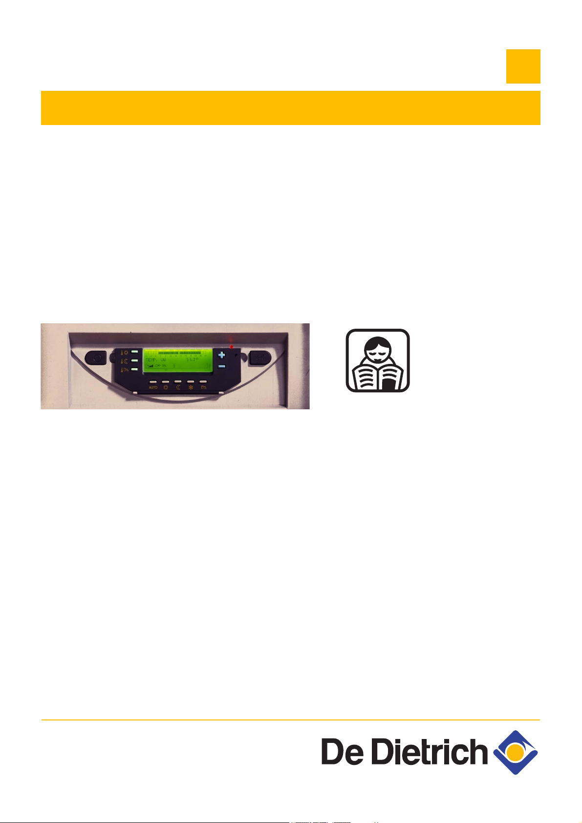
Control panel
MIT-II/E - MIT-II/H
MIT/EP - MIT/HP
QUADROPAC DUP 500
EN
User Guide
300015090-001-L
Page 2

Contents
1 Used symbols . . . . . . . . . . . . . . . . . . . . . . . . . . . . . . . . . . . . . . . . . . . . . . . . . . . . . . . . . . . . . . . . . . . . . . . . . . .3
2 Important recommendations . . . . . . . . . . . . . . . . . . . . . . . . . . . . . . . . . . . . . . . . . . . . . . . . . . . . . . . . . . . . . . .3
3 Control panel . . . . . . . . . . . . . . . . . . . . . . . . . . . . . . . . . . . . . . . . . . . . . . . . . . . . . . . . . . . . . . . . . . . . . . . . . . . .4
3.1 Electromechanical components . . . . . . . . . . . . . . . . . . . . . . . . . . . . . . . . . . . . . . . . . . . . . . . . . . . . . . . . . . . . . . . . . . . . . . . . . . . . .4
3.2 Display . . . . . . . . . . . . . . . . . . . . . . . . . . . . . . . . . . . . . . . . . . . . . . . . . . . . . . . . . . . . . . . . . . . . . . . . . . . . . . . . . . . . . . . . . . . . . . . .5
3.3 Keys accessible when the flap is closed . . . . . . . . . . . . . . . . . . . . . . . . . . . . . . . . . . . . . . . . . . . . . . . . . . . . . . . . . . . . . . . . . . . . . .6
3.4 Keys accessible when the flap is open. . . . . . . . . . . . . . . . . . . . . . . . . . . . . . . . . . . . . . . . . . . . . . . . . . . . . . . . . . . . . . . . . . . . . . . .6
3.5 Operating mode . . . . . . . . . . . . . . . . . . . . . . . . . . . . . . . . . . . . . . . . . . . . . . . . . . . . . . . . . . . . . . . . . . . . . . . . . . . . . . . . . . . . . . . . .7
4 Heating and domestic hot water temperature setting . . . . . . . . . . . . . . . . . . . . . . . . . . . . . . . . . . . . . . . . . . .9
4.1 Heating temperature setting . . . . . . . . . . . . . . . . . . . . . . . . . . . . . . . . . . . . . . . . . . . . . . . . . . . . . . . . . . . . . . . . . . . . . . . . . . . . . . . .9
4.2 DHW set temperature. . . . . . . . . . . . . . . . . . . . . . . . . . . . . . . . . . . . . . . . . . . . . . . . . . . . . . . . . . . . . . . . . . . . . . . . . . . . . . . . . . . . .9
5 Programming . . . . . . . . . . . . . . . . . . . . . . . . . . . . . . . . . . . . . . . . . . . . . . . . . . . . . . . . . . . . . . . . . . . . . . . . . . .10
5.1 Selecting a programme . . . . . . . . . . . . . . . . . . . . . . . . . . . . . . . . . . . . . . . . . . . . . . . . . . . . . . . . . . . . . . . . . . . . . . . . . . . . . . . . . .10
5.2 Hot water programme. . . . . . . . . . . . . . . . . . . . . . . . . . . . . . . . . . . . . . . . . . . . . . . . . . . . . . . . . . . . . . . . . . . . . . . . . . . . . . . . . . . .10
5.3 Auxiliary programme. . . . . . . . . . . . . . . . . . . . . . . . . . . . . . . . . . . . . . . . . . . . . . . . . . . . . . . . . . . . . . . . . . . . . . . . . . . . . . . . . . . . .10
5.4 Customising the programmes. . . . . . . . . . . . . . . . . . . . . . . . . . . . . . . . . . . . . . . . . . . . . . . . . . . . . . . . . . . . . . . . . . . . . . . . . . . . . .10
5.5 Resetting the programmes . . . . . . . . . . . . . . . . . . . . . . . . . . . . . . . . . . . . . . . . . . . . . . . . . . . . . . . . . . . . . . . . . . . . . . . . . . . . . . . .10
6 "User" settings . . . . . . . . . . . . . . . . . . . . . . . . . . . . . . . . . . . . . . . . . . . . . . . . . . . . . . . . . . . . . . . . . . . . . . . . .11
6.1 Table of "User" setting . . . . . . . . . . . . . . . . . . . . . . . . . . . . . . . . . . . . . . . . . . . . . . . . . . . . . . . . . . . . . . . . . . . . . . . . . . . . . . . . . . .12
6.2 Customising the programmes. . . . . . . . . . . . . . . . . . . . . . . . . . . . . . . . . . . . . . . . . . . . . . . . . . . . . . . . . . . . . . . . . . . . . . . . . . . . . .15
6.3 Miscellaneous settings . . . . . . . . . . . . . . . . . . . . . . . . . . . . . . . . . . . . . . . . . . . . . . . . . . . . . . . . . . . . . . . . . . . . . . . . . . . . . . . . . . .16
6.4 Setting the time and the date - Summer time . . . . . . . . . . . . . . . . . . . . . . . . . . . . . . . . . . . . . . . . . . . . . . . . . . . . . . . . . . . . . . . . . .16
7 Message . . . . . . . . . . . . . . . . . . . . . . . . . . . . . . . . . . . . . . . . . . . . . . . . . . . . . . . . . . . . . . . . . . . . . . . . . . . . . . .16
8 Maintenance. . . . . . . . . . . . . . . . . . . . . . . . . . . . . . . . . . . . . . . . . . . . . . . . . . . . . . . . . . . . . . . . . . . . . . . . . . . .17
8.1 Maintenance contract . . . . . . . . . . . . . . . . . . . . . . . . . . . . . . . . . . . . . . . . . . . . . . . . . . . . . . . . . . . . . . . . . . . . . . . . . . . . . . . . . . . .17
8.2 Fault finding . . . . . . . . . . . . . . . . . . . . . . . . . . . . . . . . . . . . . . . . . . . . . . . . . . . . . . . . . . . . . . . . . . . . . . . . . . . . . . . . . . . . . . . . . . .17
9 Diagnosing breakdowns . . . . . . . . . . . . . . . . . . . . . . . . . . . . . . . . . . . . . . . . . . . . . . . . . . . . . . . . . . . . . . . . . .18
2
MIT-II - MIT/P - QUADROPAC DUP 500 14/04/2010 - 300015090-001-L
Page 3

Congratulations on choosing a De Dietrich product, a product of quality. We strongly recommend that you read the following instructions in
order to guarantee the optimal operation of your appliance. We are sure that you will not be disappointed and that it will satisfy all of your
expectations.
1 Used symbols
Caution danger
Risk of injury and damage to equipment. Attention must be
paid to the warnings on safety of persons and equipment
Specific information
Information must be kept in mind to maintain comfort
Refer to another manual or other pages in this instruction
Z
manual
DHW: Domestic hot water
MIT: Indoor module fitted with a Diematic 3 control panel
HP or PAC: Heat pump.
2 Important recommendations
For a proper operating of the boiler, follow carefully the
instructions.
Any intervention on the appliance and heating equipment
must be carried out by a qualified technician.
The manufacturer is not liable for any improper use of the
appliance or failure to maintain or install the unit correctly
(the user shall take care to ensure that the system is
installed by a qualified fitter).
14/04/2010 - 300015090-001-L MIT-II - MIT/P - QUADROPAC DUP 500
3
Page 4
3 Control panel
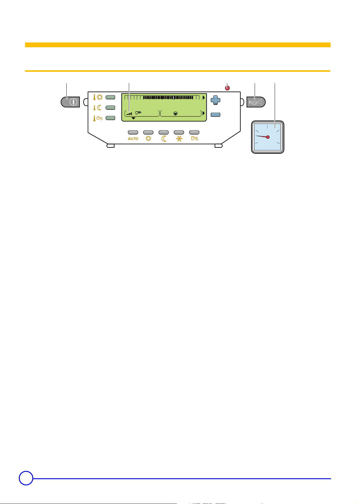
3.1 Electromechanical components
2*
0 2 4 6 8 1012141618202224
SUNDAY
bar
1. Main ON/OFF switch
To take advantage of the pump cleaning function, do not switch
off the appliance in summer. Use the Summer mode for the
desired heating shutdown period.
See: Operating mode.
Z
If a remote control CDI 2 is connected, it will have no display
when the general switch is in the off position
2. Pressure gauge
* Depending on the model of the appliance, the pressure gauge
is manual (dial display) or automatic (pictogram display).
3. Alarm indicator
.
A
C000142_00
-04
3
4
2*1
2
13
0
4
bar
- Red indicator: The PAC is safe
- Green indicator: normal operation
- Red control light is flashing: Sensor fault
4. Reset button
4
MIT-II - MIT/P - QUADROPAC DUP 500 14/04/2010 - 300015090-001-L
Page 5

3.2 Display
2
0 2 4 6 8 1012141618202224
1
1 Text and numerical display
2 Graphic bar displaying the programme on circuit A or B (in
zone 9)
3 Light area: Nighttime period
4 Dark area: Daytime period
5 Flashing cursor showing the current time
6 Number display (current time, adjusted values, parameters,
etc.)
7 Active programme display, P1, P2, P3, P4
or
E: Summer mode activated - heating OFF
8 Flashing arrows when the
adjust the displayed parameter
9 Circuit operation symbols
Opening the 3-way valve
>
=
Closing the 3-way valve
Displayed circuit pump on
:
A, B Name of the circuit displayed
10 Symbol displayed above the active operating mode
or keys should be used to
SUNDAY
bar
3 4 5 6 7
A
BC
91011
11 Symbols indicating that the following inputs/outputs are
D
X
Y
#
D
E
X
Y
8
active
ROE-II - ROE+ - SOLO - NAPO - ROI+ - ROE-H
PAC is operating in Hot or Cold mode
PAC is operating in Hot mode with additional electrical heating
at stage 1
PAC is operating in Hot mode with additional electrical heating
at stage 2
Additional electrical heating operating, stage 1. PAC off
Additional electrical heating operating, stage 2. PAC off
DHW production pending with the thermodynamic unit
Forced "summer" condition
ROE+ TH
PAC is operating in Hot mode with 1 compressor
PAC is operating in Hot mode with 2 compressor
PAC is operating in Hot mode with 2 compressors and 1 backup provision
PAC is operating in Hot mode with 2 compressors and 2 backup provision
Additional electrical heating operating, stage 1. PAC off
Additional electrical heating operating, stage 2. PAC off
DHW production pending with the thermodynamic unit
Forced "summer" condition
#
Water pressure display, user interface
Insufficient pressure: add water (0 - 0.5 bar)
Addition of water recommended (0.5 - 1 bar)
U
Pressure correct (1 - 2 bar)
T
Too much pressure (> 2 bar)
14/04/2010 - 300015090-001-L MIT-II - MIT/P - QUADROPAC DUP 500
5
Page 6
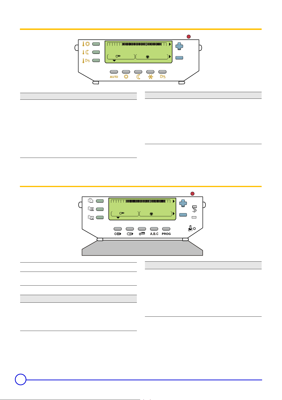
3.3 Keys accessible when the flap is closed
024681012141618202224
SUNDAY
A
Temperature setting keys
2%
2$
2
/
Daytime temperature
Nighttime temperature
Domestic hot water temperature
Is used to adjust the selected temperature
When one of these keys is pressed, the active time
programme corresponding to the circuit is displayed in the
graphic bar
3.4 Keys accessible when the flap is open
024681012141618202224
SUNDAY
C000142_02
Operating mode selection keys
AUTO
%
$
.
A
A
-04
Heating according to the time programme
Forced operation at Daytime temperature
Forced operation at Nighttime temperature
Antifreeze mode
Tank load enabled mode
STANDARD
#
STANDARD
K
Key for access to setting and measurements
J
I
H
Manual "Summer" shutdown key
"Standard" programme key
Reset of all time programmes.
Fitter settings access key
Page scrolling
Line scrolling
Return to the previous line
6
C000142_03
Programming keys
%O
$P
S
A.B
PROG
MIT-II - MIT/P - QUADROPAC DUP 500 14/04/2010 - 300015090-001-L
-04
Input (per 1/2 hour) of the Daytime Temperature period
Input (per 1/2 hour) of the Nighttime Temperature period
Return key
Circuit display selection key
Active heating programme selection key (P1, P2, P3 or
P4)
Page 7
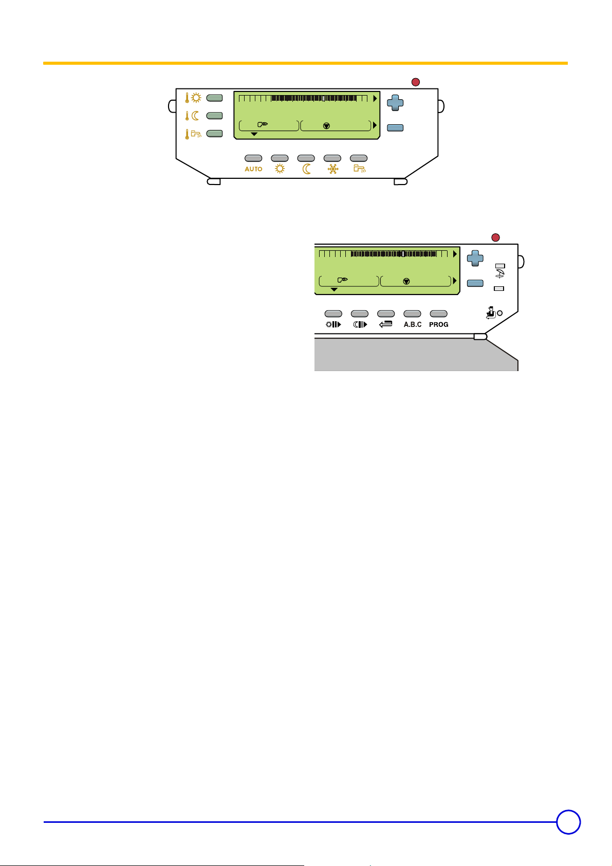
3.5 Operating mode
0 2 4 6 8 1012141618202224
SUNDAY
A
Select the operating modes using the AUTO -%-$-. keys.
These keys simultaneously control all circuits connected.
To modify the operating mode (AUTO, Daytime
for only one of the heating circuits, use the remote control
corresponding to this circuit.
An override applied to the remote control takes priority over the
override selected on the central regulator.
` AUTO key = Automatic mode
Heating according to the time programme.
See: Programming.
Z
` Key
The heating operates according to the Daytime temperature,
independently of the timed programmes.
` Key
The heating operates according to the Nighttime temperature,
independently of the timed programmes.
` Key
Domestic hot water production is enabled, independently of the time
programme.
` Key
The heating is off but the installation is monitored and protected
against frost.
The antifreeze mode protects:
- The installation if the outside temperature is lower than 3°C
- The room temperature if a remote control is connected and the
= Daytime mode
%
= Night mode
$
= Tank load enabled mode
= Antifreeze mode
.
(factory setting).
room temperature is lower than 6 °C (factory setting).
or Nighttime $)
%
C000142_02
` Key
024681012141618202224
Key
function is activated, to switch to Cooling mode.
Z
This function is independent of the "automatic heating shutdown"
function in summer when the outside temperature exceeds the
outside temperature for "heating shutdown".
#
SUNDAY
is used to cut off the heating and, if the corresponding
#
See menu #HEAT PUMP, parameter REFR.:
When the heating is off during the "summer" mode, the pumps
are started up once a week for one minute in order to prevent
fouling.
The MIT interior hydraulic module operates in COOLING mode
only:
- During the
-
and
if the outside temperature is higher than the instruction
WIN
+
Do not use or modify this programme when operating with
the QUADROPAC domestic hot water tank.
-04
(Located under the flap) = SUMMER mode / Cooling
A
A
STANDARD
C000142_03
DAY
period on timed programmes A and B,
SUM/WIN BAND
(Factory setting: 22 + 4 = 26 °C).
-04
SUM/
Antifreeze protection is guaranteed for each heating circuit,
regardless of the setting on the corresponding room
temperature sensor. The room temperature in "antifreeze"
mode is preset to +6 °C. This value can be modified if a room
sensor is fitted.
See: Table of "User" setting.
Z
14/04/2010 - 300015090-001-L MIT-II - MIT/P - QUADROPAC DUP 500
7
Page 8

Brief touch Several brief touches 1 long touch (5 seconds)
AUTO key Depending on the situation:
- Cancellation of the Daytime or
Nighttime mode
- Confirmation of the antifreeze
setting (or after 2 minutes)
Key%/
Key
Key
Key # (Located
under the flap)
$
.
Temporary activation (Until midnight)
The arrow above the key flashes.
Temporary activation
Set the number of days' absence
(current day = 1) using keys
(up to 99 days).
The arrow above the key flashes.
Cancellation: The antifreeze mode is
cancelled when the number of
antifreeze days is reset to zero or when
the set time has elapsed.
Temporary activation (Until midnight)
The arrow above the key flashes.
__First press: Permanent activation
and
_
_
Deferred temporary activation:
- First brief touch: Set the number of
days' absence (current day = 1) using
keys
- Second brief touch: Set the start
month using keys
- Third brief touch: Set the start day
using keys
The arrow above the key flashes until
the start day and then becomes steady.
Cancellation: The antifreeze mode is
cancelled when the number of
antifreeze days is reset to zero or when
the set time has elapsed
Second depression: Deactivation Permanent activation
and (up to 99 days).
and .
and .
.
Cancels the message SHOW REM.
CTRL which signals the presence of an
override on a remote control.
The AUTO mode is forced on all
existing heating circuits.
Permanent activation
The arrow above the key is steady.
Permanent activation
The arrow above the key is steady.
The permanent "antifreeze"
mode can also be selected
using the TELCOM 2 remote
voice monitoring module
delivered as an option.
The arrow above the key is steady.
The heating is off.
The symbol SU appears.
Second depression: Deactivation
8
MIT-II - MIT/P - QUADROPAC DUP 500 14/04/2010 - 300015090-001-L
Page 9

4 Heating and domestic hot water temperature
setting
024681012141618202224
SUNDAY
A
2%
2
Comfort temperature - Cooling
Reduced temperature
2$
Domestic hot water temperature
4.1 Heating temperature setting
The comfort and reduced temperatures are set separately for each
circuit:
- Select the comfort temperature or the reduced temperature for the
desired circuit by successively pressing key
- Set the temperature using keys
The graphic bar displays the heating programme for the
displayed circuit for the current day.
End of setting: Press the AUTO key or after 2 minutes.
and .
2%
or
2$
.
2
-04
Factory setting Adjustment range
20 °C
25 °C
16 °C
FL.HE.
5 to 30 °C
In steps of 0.5°C
22 to 30 °C
In steps of 0.5°C
5 to 30 °C
In steps of 0.5°C
),
C000142_02
Temperature
%
$
* Is displayed if the following 2 conditions are satisfied:
• In summer mode, when the room temperature measured by the
• In parallel, depending on the outside temperature, automatic
DAY TEMP. A
ROOM REFR.T. *
NIGHT TEMP. A
- at least one room sensor is connected on a circuit which is
configured in underfloor heating (
- cooling mode on.
sensor is higher than the set point ROOM REFR.T., the cooling
mode starts up. The cooling mode shuts down when the room
temperature measured is lower than ROOM REFR.T. -0.5°C.
cooling remains on.
4.2 DHW set temperature
- Select the domestic hot water temperature using key
set the temperature using keys
If there is no domestic hot water sensor, pressing this key has
no effect.
- End of setting: Press the AUTO key or after 2 minutes.
14/04/2010 - 300015090-001-L MIT-II - MIT/P - QUADROPAC DUP 500
or .
2
and
Temperature Adjustment range Factory setting
Domestic hot
water
2
If DHW consumption is high, increase the domestic hot water
set temperature to 60°C.
10 to 80 °C
In steps of 5°C
55 °C
9
Page 10

5 Programming
5.1 Selecting a programme
The DIEMATIC 3 control unit includes 4 heating programmes:
- 1 fixed programme P1, activated in the factory.
- 3 custom programmes P2, P3, P4 to adapt to the lifestyle of the
occupants.
Programme Day Daytime period
P1 Monday - Sunday 6:00 - 22:00
P2 (Factory setting) Monday - Sunday 4:00 - 21:00
P3 (Factory setting) Monday - Friday 5:00 - 8:00, 16:00 - 22:00
Saturday - Sunday 7:00 - 23:00
P4 (Factory setting) Monday - Friday 6:00 - 8:00, 11:00 - 13:30, 16:00 - 22:00
Saturday 6:00 - 23:00
Sunday 7:00 - 23:00
Allocation of a programme to a circuit:
- Select the circuit using key A.B.
- Select the programme using the PROG key.
- The programme selected is active in automatic mode.
The programme for the current day can be displayed on the
graph bar using key
5.2 Hot water programme
The DIEMATIC 3 control unit includes a custom domestic hot water programme.
The programme for the current day can be displayed on the
graph bar using key
Programme Day Filling enabled
Tank (Factory setting) Monday - Sunday 2:00 - 6:00
MIT
For correct operation, we recommend activating timed programmes
DHW and AUX at night to:
- Take advantatge of off-peak tariffs.
- Avoid having non-heating periods which are too long.
- Avoid switching from cold to hot operation several times a day
when the cooling mode is activated during the daytime .
.
QUADROPAC
Programme 2 hours of DHW loading before a large draw-off (shower,
bath, etc.).
2%
or 2$.
5.3 Auxiliary programme
The DIEMATIC 3 control unit includes a custom programme on the auxiliary outlet.
Programme Day Filling enabled
AUX (Factory setting) Monday - Sunday 6:00 - 22:00
Note: When you set parameter S.AUX: to AP. DHW, timed programme DHW is copied to timed programme AUX.Programme AUX can be
customised.
5.4 Customising the programmes
See: 6.2 Customising the programmes (P2, P3 or P4).
Z
5.5 Resetting the programmes
Press the STANDARD key for 5 seconds:
- All customised programmes are replaced with their factory setting.
- Programme P1 is assigned to all heating circuits.
10
MIT-II - MIT/P - QUADROPAC DUP 500 14/04/2010 - 300015090-001-L
Page 11

6 "User" settings
0 2 4 6 8 1012141618202224
SUNDAY
A
A
STANDARD
Key for access to setting and measurements
Page scrolling
J
Line scrolling
I
Back to the title or the previous line
H
Programming keys
%O
$P
Input (per 1/2 hour) of the Daytime Temperature period (Dark
area)
Input (per 1/2 hour) of the Nighttime Temperature period (Light
area)
Return key
S
When the flap is open, the keys are used to display measurements,
programme modifications and the settings of the various parameters.
The various settings and programmes are saved even when the
power supply is cut off.
C000142_03
-04
14/04/2010 - 300015090-001-L MIT-II - MIT/P - QUADROPAC DUP 500
11
Page 12

6.1 Table of "User" setting
The different adjustable parameters are listed in their order of
appearance.
Display
#MEASURES Allows the values below to be read
TEMP.MIT x x x x x x Water temperature in the MIT-II module or
HP FLOW TEMP. x x x Water temperature at the PAC outlet - -
SOURCE TEMP. x Refrigerant temperature at the heat pump source
COLD TEMP. x x Temperature of the PAC cold circuit - -
EVAPORATOR T. x Refrigerant temperature at the fin tube
OUTLET TEMP. B* x x x x x Water temperature in circuit B (Flow sensor) - -
WATER TEMP. * x x x x x Tank water temperature - -
ROOMTEMP. A* x x x x x Room temperature A - -
ROOMTEMP. B* x x x x x Room temperature B - -
OUTSIDE TEMP. x x x x x Outside temperature measured by the MIT-II
HP RETURN TEMP x x Return temperature - -
HP FLOW TEMP. x x Flow temperature - -
FLUID EVAP.T. x x Fin tube exchanger refrigerant temperature - -
FLUID COND.T. x x Refrigerant temperature at the heat exchanger - -
HOT GAS TEMP. x Refrigerant temperature at the compressor outlet - -
HP OUTSIDE T. x x x x Outside temperature measured by the PAC - -
HP FLOW TEMP. x Water temperature at the PAC outlet - -
HP RETURN TEMP x Return temperature - -
HP AIR IN T. x Outside temperature at the heat pump - -
EVAPORATOR T. x Refrigerant temperature at the fin tube
HOT GAS TEMP. x Compressor outlet temperature - -
PRESSION(BAR) x x x x x x Water pressure display - -
NB IMP.COMP. x x x x Number of PAC start-ups - -
NB IMP.COMP.1 x Number of start-ups on compressor 1 - -
RUNTIME COMP. x x x x x x Number of PAC operating hours
NB IMP.COMP.2 x Number of start-ups on compressor 2 - -
RUNTIME.COMP.2 x Number of hours' operation of compressor 2 - -
CTRL x x x x x x Information reserved for the technician (Diematic
* The line or title is only displayed for the options, circuits or sensors actually connected
ROE-II ROE-H ROE+ ROE+TH SOLO,
NAPO
At the end of the intervention, the data is memorised after 2 minutes
or by pressing the AUTO key.
ROI+
heating zone in the Quadro
end
exchanger outlet
module
exchanger outlet
Number of hours' operation of compressor 1
programme version)
Parameter set
Factory
setting
.
Adjustme
nt range
--
--
--
--
--
--
--
12
MIT-II - MIT/P - QUADROPAC DUP 500 14/04/2010 - 300015090-001-L
Page 13

Display
#PROG. CIRC.A * x x x x x x Heating programme for circuit A if used
PROG EVERY DAY P2 x x x x x x Used to programme every day of the week
PROG MONDAY P2
PROG TUESDAY P2
PROG WEDNESDAY
P2
PROG THURSDAY P2
PROG FRIDAY P2
PROG SATURDAY P2
PROG SUNDAY P2
PROG EVERY DAY P3 x x x x x x Used to programme every day of the week
PROG MONDAY P3
PROG TUESDAY P3
PROG WEDNESDAY
P3
PROG THURSDAY P3
PROG FRIDAY P3
PROG SATURDAY P3
PROG SUNDAY P3
PROG EVERY DAY P4 x x x x x x Used to programme every day of the week
PROG MONDAY P4
PROG TUESDAY P4
PROG WEDNESDAY
P4
PROG THURSDAY P4
PROG FRIDAY P4
PROG SATURDAY P4
PROG SUNDAY P4
#PROG. CIRC.B * x x x x x x Heating programme for circuit B if used
#PROG. AUXIL x x x x x x Auxiliary contact programming
#PROG. DHW*
* The line or title is only displayed for the options, circuits or sensors actually connected.
ROE-II ROE-H ROE+ ROE+TH SOLO,
xxx x xx
xxx x xx
xxx x xx
x x x x x x DHW tank programming (if the domestic hot
NAPO
ROI+
See also:
Z
Customising the programmes.
simultaneously.
Each day can subsequently be individually
modified.
simultaneously.
Each day can subsequently be individually
modified.
simultaneously.
Each day can subsequently be individually
modified.
Lines as circuit A
Lines as circuit A
water sensor is connected)
Parameter set
Factory
setting
Adjustme
nt range
--
14/04/2010 - 300015090-001-L MIT-II - MIT/P - QUADROPAC DUP 500
13
Page 14

Display
#SETTING x x x x x x The parameters are set using keys or .
CONTRAST DISP. x x x x x x Adjusting the display contrast - -
BACK LIGHT xxx x xxON: The lighting is permanent if the circuit is in
SUM/WIN x x x x x x Summer/winter setting 22 °C 15 to
CALIBR. OUT x x x x x x Outside sensor calibration 0.0 -5.0 to
CALIBR. ROOM A * x x x x x x Calibration of the room sensor on circuit A 0.0 -5.0 to
OFFSET ROOM A * x x x x x x Room offset on circuit A 0.0 -5.0 to
OFFSET ROOM B * x x x x x x Room offset on circuit B 0.0 -5.0 to
ANTIFR. ROOM A * x x x x x x Room temperature antifreeze activation on circuit A6 °C 0.5 to
CALIBR. ROOM B * x x x x x x Calibration of the room temperature sensor on
ANTIFR. ROOM B * x x x x x x Room temperature at which the antifreeze mode
#TIME . DAY x x x x x x The parameters are set using keys
HOURS xxx x xx
MINUTE xxx x xx
DAY xxx x xx
MONTH xxx x xx
DATE xxx x xx
YEAR xxx x xx
SUM. TIME: xxx x xxAUTO: automatic switch to summer time on the
* The line or title is only displayed for the options, circuits or sensors actually connected.
ROE-II ROE-H ROE+ ROE+TH SOLO,
NAPO
ROI+
See also: Miscellaneous settings.
Z
Daytime period
Night period, the backlighting is ECO.
ECO: If the circuit displayed is in Nighttime
period, the lighting is on for 2 minutes if a key on
the keyboard is pressed.
OFF: The display is never lit
circuit B
is activated on circuit B
See also: Setting the time and the date
Z
- Summer time.
last Sunday in March and back to winter time on
the last Sunday in October.
MANU: for countries where the time change is
done on other dates or is not in use.
Parameter set
. If the circuit displayed is in a
or .
Factory
setting
--
ON ON, ECO
0.0 -5.0 to
6 °C 0.5 to
--
AUTO AUTO or
Adjustme
nt range
or OFF
30 °C -
OFF
+5.0 K
+5.0 K
+5.0 K
+5.0 K
20 °C
+5.0 K
20 °C
MANU
14
MIT-II - MIT/P - QUADROPAC DUP 500 14/04/2010 - 300015090-001-L
Page 15

6.2 Customising the programmes
Write the customized programmes in the tables below, then save
them as follows:
1. Open the cover to access to the setting and programme keys.
2. Press key
#PROG. CIRC.B - #PROG. AUXIL - #PROG. DHW)
3. Select successive lines using key
The programming selected for line PROG EVERY DAY is
automatically copied to the other lines but can still be
individually modified for each day.
4. Use key
areas on the graphic display).
Use key
(dark areas on the graphic display).
Use the return key
5. Proceed similarly for each connected circuit, if necessary.
6. When programming is completed, press key AUTO. Otherwise,
the programme will be automatically saved after 2 minutes.
To reset to the factory settings, press the key STANDARD for
5 seconds.
to select the paragraph (#PROG. CIRC.A -
J
.
I
to define the daytime periods (per 1/2 hour) (dark
%O
to define the Nighttime periods (per 1/2 hour)
$P
if you make a mistake.
S
#PROG. CIRC.A
Day Daytime period
Monday
Tuesday
Wednesday
Thursday
Friday
Saturday
Sunday
#PROG. CIRC.B
Day Daytime period
Monday
Tuesday
Wednesday
Thursday
Friday
Saturday
Sunday
#PROG. AUXIL
Day Daytime period
Monday
Tuesday
Wednesday
Thursday
Friday
Saturday
Sunday
#PROG. DHW: Domestic hot water
Day Daytime period
Monday
Tuesday
Wednesday
Thursday
Friday
Saturday
Sunday
14/04/2010 - 300015090-001-L MIT-II - MIT/P - QUADROPAC DUP 500
15
Page 16

6.3 Miscellaneous settings
1. Use the J key to select the paragraph #SETTING.
2. Display the desired parameter using key
3. Set the value of the parameter by pressing buttons
` SUM/WIN: Automatic heating shutdown instruction.
Used to set the outside temperature above which heating will be
shut down.
- The symbol SU appears.
If this parameter is set to NO, the heating is never shut down
automatically.
The cooling mode is activated when the following conditions are
satisfied:
- Parameter
- Outside temperature > SUM/WIN instruction +
- The circuit is configured as underfloor heating or convector fan.
See: Technical and installation instructions for MIT.
Z
` CALIBR. OUT: Outside sensor calibration
Used to correct the outside temperature.
For example
Outside temperature measured = 10 °C
Temperature displayed = 11 °C
Set parameter CALIBR. OUT to -1.
Calibration only becomes effective after a few dozen seconds,
and the display is corrected only after this time.
REFR.:
:
is set to
ON
.
I
SUM/WIN BAND
and :
` ANTIFR. ROOM...: Room antifreeze
Setting the minimum room temperature which is maintained in
the antifreeze mode for each circuit.
This temperature is only checked if a room sensor is connected.
Without a room sensor, this parameter is not displayed and the
set temperature is 6 °C (not adjustable).
` CALIBR. ROOM...: Room sensor calibration
Used to correct the room temperature display.
For example
Room temperature measured = 20 °C
Temperature displayed = 19 °C
Set parameter CALIBR. ROOM... to +1.
When a remote control is connected, this setting must be made
at least 2 hours after the power is turned on, to enable the room
temperature to stabilise.
` AMB OFFSET...: Room offset - Without room sensor
Is used to set a room offset.
For example:
Set room temperature = 20 °C
Measured temperature = 19 °C
Set parameter AMB OFFSET... to +1.
The setting must be made after the temperatures have
stabilised.
:
6.4 Setting the time and the date - Summer time
1. Press the J key to select the #TIME . DAY menu
2. Display the desired parameter using key
3. Set the value of the parameter by pressing buttons
HOURS
MINUTE
DAY
MONTH
I
.
and :
DATE
YEAR
SUM. TIME: AUTO (Factory setting) - MANU
The control unit is programmed to switch automatically to
summer time on the last Sunday in March and back to winter
time on the last Sunday in October.
When the setting is on "manual", the automatic change does not
take place.
7 Message
Message Probable causes Action
SHOW REM. CTRL The message SHOW REM. CTRL signals the presence of an
override on a remote control
To cancel the overrides on all remote controls, press the AUTO
key for 5 seconds.
16
MIT-II - MIT/P - QUADROPAC DUP 500 14/04/2010 - 300015090-001-L
Page 17

8 Maintenance
The installation and maintenance of the appliance must be
carried out by a qualified professional in compliance with
the statutory texts of the codes of conduct in force.
Before working on the appliance, ensure that it is switched
off and safe.
Check the discharge on the compressor condenser for
single phase voltages.
Before working on the cooling circuit, switch off the
appliance and wait a few minutes. Some equipment such
as the compressor and the pipes can reach temperatures
higher than 100°C and high pressures, which may cause
serious burns.
8.1 Maintenance contract
We recommend taking out a maintenance contract.
Servicing frequency
8.1.1 Operations to be done at each service
: At least once a year
Maintenance operations are important for the following reasons:
- To guarantee optimum performance
- To extend the life of the equipment
- To provide an installation which offers the customer optimum
comfort over time
Take a reading of the installation's operation at each periodic service.
Refer to this reading in the maintenance log and compare it with the
commissioning data. Signal any anomalies.
Schedule a service in cold periods to check the following points:
- Operation of the defrosting process
- Setting of the thermostats and safety devices
- Thermal output by measuring the temperature difference between
the flow and the return
Preventive monitoring
- Check whether the pump stopped after a safety shutdown (Error
warning light illuminated)
- Dust and clean the external unit on the PAC
Do not pour water on it, use a rag or a sponge.
- Check the run-off in the condensates vats.
- Clean the condensates vats.
- Check the performance of the heat pump
- Carry out a visual and aural check on the entire system(normal
noises, panel detached, lagging, traces of water,...)
- Regularly check the concentration of the antifreeze fluid.
: Temperature control.
8.2 Fault finding
All work on the cooling circuit must be done by a qualified
professional, according to prevailing codes of practice and safety in
the profession (recovery of the refrigerant, brazing under nitrogen,
etc.)
All brazing work must be done by qualified brazers.
This appliance is fitted with pressurised equipment, including the
refrigeration pipes.
Use only original parts to replace a defective refrigeration
component.
Maintenance
- Check for leaks on components which guarantee the containment
of refrigerant.
- Check the electrical connections.
- Regulator function check.
- Change all parts and cables judged to be defective.
- Check all screws and nuts (cover, support, etc.)
- Change damaged sections of lagging.
- Paint the damaged parts.
- Use dehydrated nitrogen or a mixture of nitrogen and refrigerant
indicated on the rating plate.
Leak detection - Pressurised tests
- Never use oxygen or dehumidified air, danger of fire or explosion.
14/04/2010 - 300015090-001-L MIT-II - MIT/P - QUADROPAC DUP 500
:
17
Page 18

9 Diagnosing breakdowns
Display ROE-II
ROE-H
No display xxx
HP COM.FAIL xxx
MANOMETRE FAIL xxx
FAIL. MIT S. xxx
OUTSI. S.FAIL. xxx
OUTL S.B FAIL. xxx
ROOM S.A FAIL. xxx
ROOM S.B FAIL. xxx
DHW S. FAILURE xxx
FAIL. SOURCE S. xx
FAIL. PAC FLOW S. xx
COLD S.FAIL xx
COLD CIRC.FAIL x
ROE+
ROE+TH
SOLO
NAPO
ROI+ Installation malfunction/HP or
Communication error with the
PAC.
Fault on the water pressure
sensor
MIT sensor fault
Fault external sensor
Sensor fault flow circuit B
Fault room temperature sensorA- Wiring problem between the MIT module and the
Fault room temperature sensorB- Wiring problem between the MIT module and the
Domestic hot water outlet
sensor fault
Fault on the source sensor
(SOLO / NAPO) or the outside
sensor (ROE+)
Fault on the PAC flow sensor
Fault on the cold sensor
Fault on the cold circuit - A H.PRES. FAIL., HOT GAS FAIL. or L.PRES. FAIL
PAC
Meaning / Cause (listed in order of likelihood)
- Check the electricity supply
- Check that the fuses are in good working condition
ROE+: When the appliance is switched on, the
end-of-defrosting pressure switch must be
open.
NAPO: The primary flow switch must be
closed when the appliance is switched on.
Code resistance value:
ROE+: 68 kΩ
SOLO: 18 kΩ
- Thermodynamic unit off.
- Parameter HP in the #HEAT PUMP menu incorrectly
configured.
- BUS wiring problem between the MIT and the
thermodynamic unit (colours, polarities)
- MIT flat cable faulty
- Comunication pcb defective.
- Wiring problem
- The manometer is defective
- Sensor pcb defective
remote control.
- Remote control defective.
- Sensor pcb defective.
remote control.
- Remote control defective.
- Sensor pcb defective.
fault has occurred previously.
For more information, display the #DEF. HISTORY
menu.
- To eradicate this fault, switch off the control panel and
turn it back on.
When a fault is displayed followed by AUTO, this disappears automatically after a few minutes. When the fault displayed is followed by
MANU, it is necessary to reset the HP using the reset button (See section 3.1).
18
MIT-II - MIT/P - QUADROPAC DUP 500 14/04/2010 - 300015090-001-L
Page 19

Display ROE-II
ROE-H
H.PRES. FAIL. xx
ROE+
ROE+TH
SOLO
NAPO
ROI+ Installation malfunction/HP or
High Pressure fault
Installation malfunction
The PAC has been deactivated
after reaching the high pressure
limit
HOT GAS FAIL. x
L.PRES. FAIL xx
Hot gas fault The temperature between the primary and the PAC
Low Pressure fault
PAC malfunction
The PAC has been deactivated
after reaching the high pressure
limit
MOT.PROT.FAIL xx
Motor/compressor protection
PAC malfunction
Compressor fault
FLOW FAIL. xx
Flow rate fault (Only with hot
water PACs and heating with 1
compressor)
Installation malfunction
COMP.FAIL. x
HP OUT LIMIT x
Fault level: temporary - Compressor rotation
Under the lower operating limit
Installation malfunction
OUT LIMIT 1 x
OUT LIMIT 3 x
FAIL. H.P PAC x
Under the lower operating limit -
Above the upper operating limit -
Fault level: Permanent /
temporary
PAC
Meaning / Cause (listed in order of likelihood)
- Heating water flow rate too low
- Heating circulating pump defective
- Differential valve incorrectly set or incorrectly
dimensioned
- Air in the heating circuit
- Nonreturn valve in the collector open or faulty
- HP pressure switch defective
- Condensor blocked
- Regulator faulty
outlet is too high. (For example: -20°C outside - 50°C at
PAC outlet)
- Heating water flow rate too low
- Heating circulating pump defective
- Differential valve incorrectly set or incorrectly
dimensioned
- Air in the heating circuit
- Nonreturn valve in the collector open or faulty
- HP pressure switch defective
- Condensor blocked
- Regulator faulty
- System temperature too low
- Evaporator on PAC air/water frozen
- Heat source production or collector on PAC underdimensioned
- Leak in refrigerant circuit
- LP pressure switch defective
-Filter blocked
- Regulator faulty
- Glycol water concentration too weak
- Evaporator on PAC blocked
- defective
- Progressive starter faulty
-Filter blocked
- Electricity consumption too high
- Glycol water concentration too weak (< 25 %)
- Evaporator rusty
- On NAPO PAC
: Flow rate on well too low
-Filter blocked
- Absorption well and supply well inverted
- Evaporator on PAC blocked
- Antifreeze protection 2 time in 2 hours
- HP or fin tube battery sensor short circuited
When a fault is displayed followed by AUTO, this disappears automatically after a few minutes. When the fault displayed is followed by
MANU, it is necessary to reset the HP using the reset button (See section 3.1).
14/04/2010 - 300015090-001-L MIT-II - MIT/P - QUADROPAC DUP 500
19
Page 20

Display ROE-II
ROE-H
FAIL. PAC V4V xx
ROE+
ROE+TH
SOLO
NAPO
ROI+ Installation malfunction/HP or
4-way valve fault
PAC malfunction
Fault level: temporary
FAIL. PAC PUMP x
Fault level: Permanent /
temporary
FAIL.EXT.S.PAC x
Fault level: permanent in hot
mode / temporary in cold mode
FAIL.RET.S.PAC xx
FAIL. PAC FLOW S. xx
FAIL.BAT.S.PAC x
FAIL.EXCH.S.PAC x
Fault level: Permanent - Opening or short circuit on the water inlet temperature
Fault level:Permanent - Opening or short circuit on the water outlet
Fault level:Permanent - Opening or short circuit at the fin tube exchanger
Fault level: permanent in cold
mode / temporary in hot mode
HGAS S.HP FAIL x
FLOW FAIL. 6 x
Fault level:Permanent - Opening or short circuit of the refrigerant temperature
Fault level:Permanent /
temporary
FLOW FAIL. 7 x
Fault level:Permanent /
temporary
FLOW FAIL. 8 x
FAIL.EEPROM CPU x
FAIL. UNKNOWN x
MC COM.FAIL xx
Fault level: temporary - Exchanger frozen
Error EEPROM CPU - Switch off PAC and start up again
Fault unknown - Switch off PAC and start up again
Communication fault Boiler
Module
BIOS FAIL. x
CONFIG.FAIL. x
Wrong Carel box - Replace the box
Wrong coding resistor / cold
sensor combination
SHUNT/CA FAIL. x
If the contact is open and there
is a communication with the
control panel, the PAC stops
(except ROE-H)
COND. ANTI. F. x
The PAC flow temperature is too
low
DEFROST FAIL. x
AIR IN S.FAIL x
HGAS S.FAIL x
EVA.S.HP FAIL x
COND.S.HP FAIL x
HP FAIL.: ... x
Fault number if this is not
included in the list
Meaning / Cause (listed in order of likelihood)
PAC
- 4-way valve blocked open or closed
- Reversal of the heating flow and return
- Lack of refrigerant
- Regulator faulty
-No water
- Circulating pump breakdown
- Opening or short circuit on the outside temperature
sensor
sensor
temperature sensor
refrigerant temperature sensor
- Opening or short circuit of the refrigerant temperature
sensor at the heat exchanger inlet
sensor at the compressor outlet
- Exchanger frozen
- Exchanger frozen
- Change the micro-connect board
- Change the micro-connect board
- Check the wiring and the cold sensor
- Check that the back-ups are working
-
- Opening of or short circuit on the air inlet temperature
sensor
- Opening of or short circuit on the hot gas temperature
sensor
- Opening of or short circuit on the evaporator
temperature sensor
-
-
When a fault is displayed followed by AUTO, this disappears automatically after a few minutes. When the fault displayed is followed by
MANU, it is necessary to reset the HP using the reset button (See section 3.1).
20
MIT-II - MIT/P - QUADROPAC DUP 500 14/04/2010 - 300015090-001-L
Page 21

Display ROE-II
ROE-H
NO CONFIG. x
When a fault is displayed followed by AUTO, this disappears automatically after a few minutes. When the fault displayed is followed by
MANU, it is necessary to reset the HP using the reset button (See section 3.1).
ROE+
ROE+TH
SOLO
NAPO
ROI+ Installation malfunction/HP or
PAC
Meaning / Cause (listed in order of likelihood)
The PAC is not recognised - Check that the coding resistor is fitted
14/04/2010 - 300015090-001-L MIT-II - MIT/P - QUADROPAC DUP 500
21
Page 22

W
arranty
You have just purchased one of our appliances and we thank you
for the trust you have placed in our products. Please note that your
appliance will provide good service for a longer period of time if it is
regularly checked and maintained. Your fitter and our customer
support network are at your disposal at all times.
Warranty terms
Starting from the purchase date shown on the original fitter's
invoice, your appliance has a contractual guarantee against any
manufacturing defect.
The length of the guarantee is mentioned in the price catalogue.
The manufacturer is not liable for any improper use of the appliance
or failure to maintain or install the unit correctly (the user shall take
care to ensure that the system is installed by a qualified fitter). In
particular, the manufacturer shall not be held responsible for any
damage, loss or injury caused by installations which do not comply
with the following:
- applicable local laws and regulations
- specific requirements relating to the installation, such as national
and/or local regulations
- the manufacturer's instructions, in particular those relating to the
regular maintenance of the unit
- the rules of the profession
The warranty is limited to the exchange or repair of such parts as
have been recognised to be faulty by our technical department and
does not cover labour, travel and carriage costs. The warranty shall
not apply to the replacement or repair of parts damaged by normal
wear and tear, negligence, repairs by unqualified parties, faulty or
insufficient monitoring and maintenance, faulty power supply or the
use of unsuitable fuel. Sub-assemblies such as motors, pumps,
electric valves etc. are guaranteed only if they have never been
dismantled.
Italy
The duration of our warranty is shown on the certificate delivered
with the appliance.
Our liability as manufacturer may not be invoked in respect of
incorrect use of the appliance, incorrect or insufficient maintenance
thereof, or incorrect installation of the appliance (you must
therefore ensure that installation and maintenance operations are
carried out respectively by a qualified professional and by an after
sales service company).
The legislation laid down by European Directive 99/44/EEC,
transposed by Legislative Decree No. 24 of 2 February 2002
published in O.J. No. 57 of 8 March 2002, continues to apply.
Russia
The foregoing provisions in no way affect the rights of the
consumer, which are guaranteed by the legislation of the Russian
Federation as regards hidden defects.
The terms and conditions of warranty and the terms and conditions
of application of the warranty are indicated on the warranty form.
The warranty shall not apply as regards the replacement or repair
of wearing parts under normal use. Such parts include
thermocouples, injection nozzles, flame control and ignition
systems, fuses and gaskets.
Turkey
Due to the laws and regulations the product life for this product is
10 years. During that time the producer and/or the distributor has
to provide after sales services and spare parts.
Other countries
The above provisions do not restrict the benefit of the legal laws
regarding hidden defects applicable in the buyer's country.
France
The preceding dispositions are not exclusive of benefits for the
purchaser of the legal guarantee as stated in Civil Code articles
1641 to 1648.
Poland
Warranty conditions are included in the warranty card.
Switzerland
The application of the warranty is subject to the terms and
conditions of sale, delivery and warranty of the company marketing
our products.
Belgium
The preceding dispositions about the contractual guarantee are not
exclusive of profit if the need arises for the purchaser in Belgium of
the applicable legal dispositions on hidden defects.
22
MIT-II - MIT/P - QUADROPAC DUP 500 14/04/2010 - 300015090-001-L
Page 23

14/04/2010 - 300015090-001-L MIT-II - MIT/P - QUADROPAC DUP 500
23
Page 24

FR
DE DIETRICH THERMIQUE S.A.S.
www.dedietrich-thermique.fr
Direction des Ve ntes France
57, rue de la Gare
F- 67580 MERTZWILLER
+33 (0)3 88 80 27 00
+33 (0)3 88 80 27 99
DE
BE
CN
DE DIETRICH REMEHA GmbH
www.dedietrich-remeha.de
Rheiner Strasse 151
D- 48282 EMSDETTEN
+49 (0)25 72 / 23-5
+49 (0)25 72 / 23-102
info@dedietrich.de
VAN MARCKE
www.vanmarcke.be
Weggevoerdenlaan 5
B- 8500 KORTRIJK
+32 (0)56/23 75 11
DE DIETRICH
www.dedietrich-heating.com
Room 512, Tower A, Kelun Building
12A Guanghua Rd, Chaoyang District
C-100020 BEIJING
+86 (0)106.581.4017
+86 (0)106.581.4018
+86 (0)106.581.7056
+86 (0)106.581.4019
contactBJ@dedietrich.com.cn
LU
RU
AT
NEUBERG S.A.
www.dedietrich-heating.com
39 rue Jacques Stas
L- 2010 LUXEMBOURG
+352 (0)2 401 401
DE DIETRICH
www.dedietrich-otoplenie.ru
129090 г. Москва
ул. Гиляровского, д. 8
офис 52
+7 495 988-43-04
+7 495 988-43-04
dedietrich@nnt.ru
ÖAG AG
www.oeag.at
Schemmerlstrasse 66-70
A-1110 WIEN
+43 (0)50406 - 61624
+43 (0)50406 - 61569
dedietrich@oeag.at
CH
WALTER MEIER (Klima Schweiz) AG
www.waltermeier.com
Bahnstrasse 24
CH-8603 SCHWERZENBACH
+41 (0) 44 806 44 24
Serviceline +41 (0)8 00 846 846
+41 (0) 44 806 44 25
ch.klima@waltermeier.com
WALTER MEIER (Climat Suisse) SA
www.waltermeier.com
Z.I. de la Veyre B, St-Légier
CH-1800 VEVEY 1
+41 (0) 21 943 02 22
Serviceline +41 (0)8 00 846 846
+41 (0) 21 943 02 33
ch.climat@waltermeier.com
© Copyright
All technical and technological information contained in these technical instructions, as well as any
drawings and technical descriptions supplied, remain our property and shall not be multiplied
without our prior consent in writing.
Subject to alterations.
14/04/2010
AD001NU-AC
DE DIETRICH THERMIQUE
57, rue de la Gare F- 67580 MERTZWILLER - BP 30
 Loading...