

Page 1
Vivadens
Wall-hung gas condensing boilers
MCR 24
MCR 24/28 MI
MCR 30/35 MI
MCR 34/39 MI
EN
User Guide
300015874-001-01
Page 2

Contents
1 Introduction ................................................................................................4
1.1 Symbols used .......................................................4
1.2 Abbreviations ........................................................4
1.3 General ..................................................................4
1.3.1 Manufacturer’s liability .............................................4
1.3.2 Installer’s liability .....................................................5
1.3.3 User’s liability ..........................................................5
1.4 Homologations ......................................................6
1.4.1 Certifications ...........................................................6
2 Safety instructions and recommendations ..............................................7
2.1 Safety instructions ...............................................7
2.2 Recommendations ................................................8
3 Description ..................................................................................................9
3.1 General description ..............................................9
3.2 Main parts ..............................................................9
3.3 Control panel .......................................................10
4 Operating the appliance ..........................................................................11
4.1 Start the boiler ....................................................11
4.2 Reading out measured values ...........................12
4.3 Changing the settings ........................................13
4.3.1 Changing the heating temperature ........................13
4.3.2 Changing the domestic hot water
temperature ...........................................................14
4.3.3 Modifying the comfort setting (ECO) .....................14
4.3.4 Stopping the central heating or activating the Summer
mode .....................................................................15
4.3.5 Stopping domestic hot water production ...............16
4.3.6 Other settings ........................................................16
1
160513 - 300015874-001-01
Page 3

Contents
4.4 Installation shutdown .........................................17
4.5 Turning on the antifreeze function ....................18
5 Checking and maintenance .....................................................................19
5.1 General instructions ...........................................19
5.2 Periodic checks ..................................................19
5.3 Filling the system ...............................................20
5.4 Bleeding the heating system .............................21
5.5 Draining the installation .....................................24
6 Troubleshooting .......................................................................................25
6.1 Error codes ..........................................................25
6.1.1 ..............................................................................25
6.1.2 ..............................................................................25
6.1.3 Other error codes ..................................................25
6.1.4 Before contacting the installer ...............................25
6.2 Incidents and solutions ......................................26
7 Technical specifications ..........................................................................28
7.1 Technical specifications ....................................28
8 Energy savings .........................................................................................30
8.1 Energy savings ...................................................30
8.1.1 Energy-saving advice ............................................30
8.1.2 Room thermostat and settings ..............................30
9 Warranty ....................................................................................................32
9.1 General ................................................................32
9.2 Warranty terms ...................................................32
2
160513 - 300015874-001-01
Page 4

3
160513 - 300015874-001-01
Page 5
MCR 24 MCR 24/28 MI MCR 30/35 MI MCR 34/39 MI
1 Introduction
1.1 Symbols used
1. Introduction
In these instructions, various danger levels are employed to draw the
user’s attention to particular information. In so doing, we wish to
safeguard the user’s safety, obviate hazards and guarantee correct
operation of the appliance.
DANGER
Risk of a dangerous situation causing serious physical
injury.
WARNING
Risk of a dangerous situation causing slight physical
injury.
1.2 Abbreviations
1.3 General
CAUTION
Risk of material damage.
Signals important information.
¼Signals a referral to other instructions or other pages in the
instructions.
4 DHW: Domestic hot water.
4 IRC: Interactive remote control.
4 CRC: Communicating remote controller.
4 Hi: Lower heating value LHV (Nett).
4 Hs: Higher heating value HHV (Gross).
160513 - 300015874-001-01
1.3.1. Manufacturer’s liability
Our products are manufactured in compliance with the requirements
of the various applicable European Directives. They are therefore
delivered with [ marking and all relevant documentation.
4
Page 6

1. Introduction
MCR 24 MCR 24/28 MI MCR 30/35 MI MCR 34/39 MI
In the interest of customers, we are continuously endeavouring to
make improvements in product quality. All the specifications stated in
this document are therefore subject to change without notice.
Our liability as the manufacturer may not be invoked in the following
cases:
4 Failure to abide by the instructions on using the appliance.
4 Faulty or insufficient maintenance of the appliance.
4 Failure to abide by the instructions on installing the appliance.
1.3.2. Installer’s liability
The installer is responsible for the installation and inital start up of the
appliance. The installer must respect the following instructions:
4 Read and follow the instructions given in the manuals provided
with the appliance.
4 Carry out installation in compliance with the prevailing legislation
and standards.
4 Perform the initial start up and carry out any checks necessary.
4 Explain the installation to the user.
4 If a maintenance is necessary, warn the user of the obligation to
check the appliance and maintain it in good working order.
4 Give all the instruction manuals to the user.
1.3.3. User’s liability
To guarantee optimum operation of the appliance, the user must
respect the following instructions:
4 Read and follow the instructions given in the manuals provided
with the appliance.
4 Call on qualified professionals to carry out installation and initial
start up.
4 Get your installer to explain your installation to you.
4 Have the required checks and services done.
4 Keep the instruction manuals in good condition close to the
appliance.
This appliance is not intended to be used by persons (including
children) whose physcial, sensory or mental capacity is impaired or
persons with no experience or knowledge, unless they have the
benefit, through the intermediary of a person responsible for their
safety, of supervision or prior instructions regarding use of the
appliance. Care should be taken to ensure that children do not play
with the appliance.
To prevent hazardous situations from arising, if the mains lead is
damaged it must be replaced by the original manufacturer, the
manufacturer’s dealer or another suitably skilled person.
5
160513 - 300015874-001-01
Page 7
MCR 24 MCR 24/28 MI MCR 30/35 MI MCR 34/39 MI 1. Introduction
1.4 Homologations
1.4.1. Certifications
CE identification no
NOx < 70 mg/kWh
Type of connection Chimney: B
PIN 0063BQ3009
Flue gas outlet: C13,C33,C43,C53,C63,C83, C
23P
93
160513 - 300015874-001-01
6
Page 8
2. Safety instructions and recommendations MCR 24 MCR 24/28 MI MCR 30/35 MI MCR 34/39 MI
2 Safety instructions and
recommendations
2.1 Safety instructions
DANGER
If you smell gas:
1. Do not use a naked flame, do not smoke, do not
operate electrical contacts or switches ( doorbell,
light, motor, lift, etc..).
2. Shut off the gas supply.
3. Open the windows.
4. Evacuate the premises.
5. Call your fitter.
DANGER
If you smell flue gases:
1. Switch the appliance off.
2. Open the windows.
3. Evacuate the premises.
4. Call your fitter.
WARNING
Depending on the settings of the appliance:
4 The temperature of the flue gas conduits may exceed
60°C.
4 The temperature of the radiators may reach 85°C.
4 The temperature of the domestic hot water may reach
65°C.
CAUTION
Do not neglect to service the appliance:
4 For completely safe and optimum operation, you
must have your boiler regularly serviced by an
approved installer.
7
160513 - 300015874-001-01
Page 9
MCR 24 MCR 24/28 MI MCR 30/35 MI MCR 34/39 MI 2. Safety instructions and recommendations
2.2 Recommendations
WARNING
Only qualified professionals are authorised to work on the
appliance and the installation.
4 Regularly check the water pressure in the installation (minimum
pressure 0,8 bar, recommended pressure between 1,5 and 2,0
bar).
4 Keep the appliance accessible at all times.
4 Never remove or cover labels and rating plates affixed to the
appliance. Labels and rating plates must be legible throughout the
entire lifetime of the appliance.
4 The appliance should be on Summer or Antrifreeze mode rather
than switched off to guarantee the following functions:
- Anti blocking of pumps
- Antifreeze protection
160513 - 300015874-001-01
8
Page 10
12
14
15
13
16
T004250-A
3. Description MCR 24 MCR 24/28 MI MCR 30/35 MI MCR 34/39 MI
3 Description
3.1 General description
Wall-hung gas condensing boilers
4 MCR 24 - Heating only.
4 MCR ../.. MI - Heating and instantaneous domestic hot water
production.
4 Low pollutant emissions.
4 Flue gas discharge via a forced flue, chimney, bi-flow or 3CE type
connection.
The MCR 24 boiler can be connected to a 80 or 130 litre tank to
produce domestic hot water.
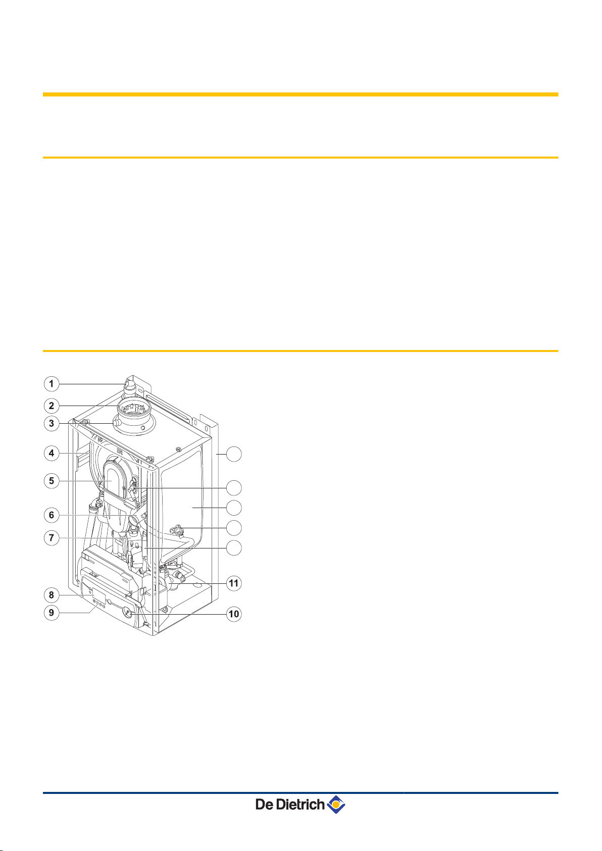
3.2 Main parts
1
2
3
4
5
6
7
8
9
10
11
12
13
14
Automatic air vent
Flue gas discharge pipe / Combustive air
Outlet for measuring combustion gases
Heat exchanger
Air/gaz canal
Fan air inlet
Gas block
Display
Control panel
Pressure gauge
Circulating pump
Ignition transformer
Expansion vessel heating circuit
(Except MCR 34/39 MI model )
Ignition/ionization electrode
15
16
9
Stand-off frame (optional), Mounting frame, delivered with
the boiler
Water pressure sensor
160513 - 300015874-001-01
Page 11
MCR 24 MCR 24/28 MI MCR 30/35 MI MCR 34/39 MI 3. Description
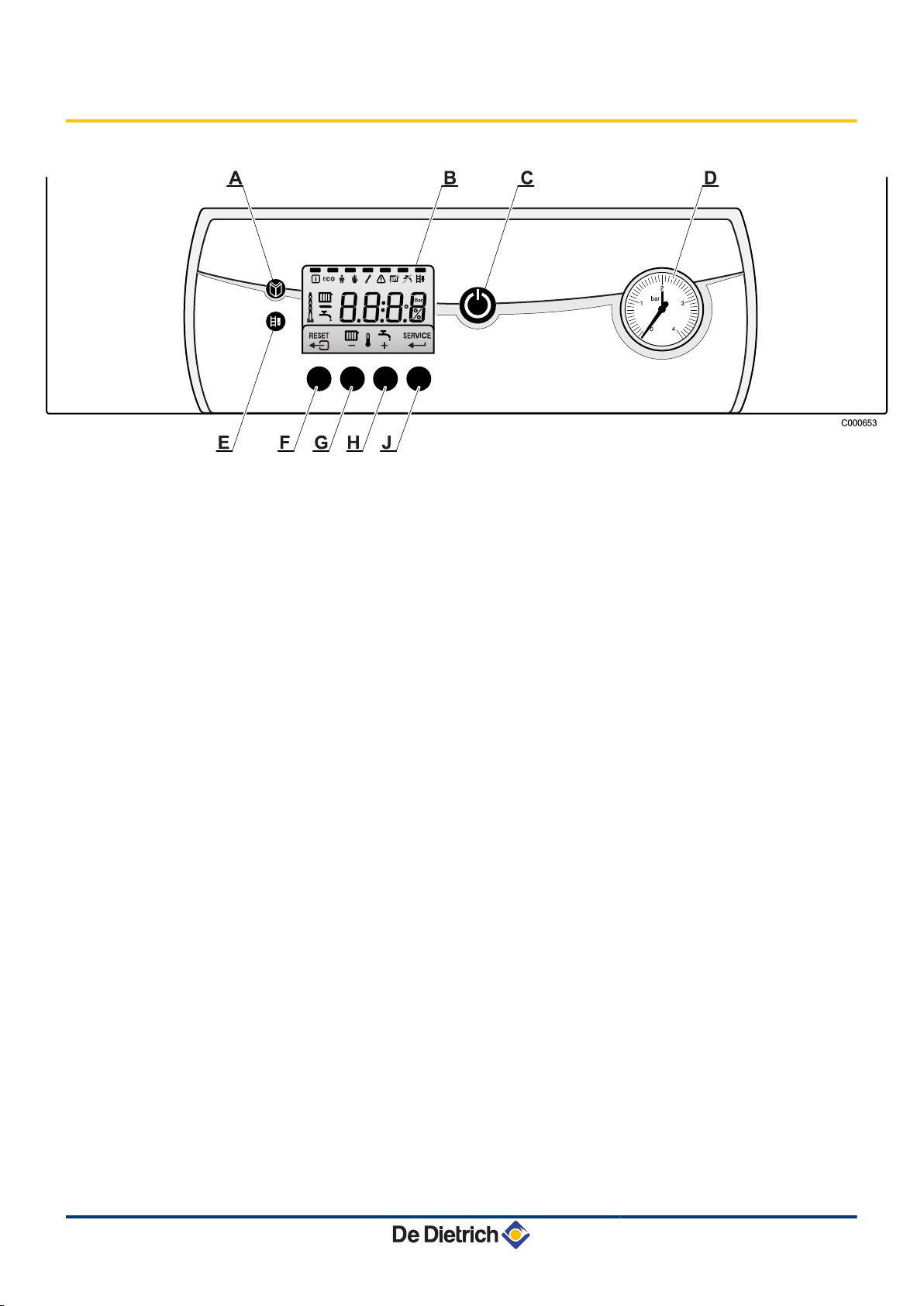
3.3 Control panel
A
B
C
D
E
F
G
H
J
The display indicates the state of the boiler and any errors. The
symbols located above the function keys indicate their current
function.
Pressing on any key will display the current status of the boiler and
the current command code. If there is a fault, the corresponding code
continues to be displayed.
Menu key
Display
Main ON/OFF switch
Pressure gauge
Sweep key
( or RESET key
Heating temperature key or -
DHW temperature key or +
SERVICE or U key
160513 - 300015874-001-01
10
Page 12

T000164-B
A000785-A
A000787-A
4. Operating the appliance
MCR 24 MCR 24/28 MI MCR 30/35 MI MCR 34/39 MI
4 Operating the appliance
4.1 Start the boiler
1. Check the water pressure in the installation.
2. Open the gas valve.
3. Throw the boiler’s ON / OFF switch.
4. The start-up cycle begins. It lasts 2 minutes and cannot be
interrupted.
During the start-up cycle, the display shows the following
information:
fK[xx
pK[xx
: Software version
: Parameter version
The version numbers are displayed alternately.
5. When the start-up cycle is finished, the display shows 0. The
boiler is now operational.
11
160513 - 300015874-001-01
Page 13

T000138-A
MCR 24 MCR 24/28 MI MCR 30/35 MI MCR 34/39 MI 4. Operating the appliance
4.2 Reading out measured values
The following values can be displayed in the information menu Q:
4 t1 = Flow temperature (°C)
4 t2 = Return temperature (°C)
4 t3 = Domestic hot water temperature (°C)
4 t4 = Outside temperature (°C)
fl = Ionization current (μA)
4
4 Mf = Fan speed (rpm)
1. Press the f key. The symbol Q flashes.
2. To access the parameters, press key S.
3. Press the [+] key successively to scroll down the various
parameters.
4. Press the
key 2 times to return to the current operating mode
>
160513 - 300015874-001-01
12
Page 14

T000147-A
GA,
HF,
4. Operating the appliance MCR 24 MCR 24/28 MI MCR 30/35 MI MCR 34/39 MI
4.3 Changing the settings
4.3.1. Changing the heating temperature
If an outside temperature sensor or an OpenTherm control
system is fitted, the heating flow temperature is adjusted
automatically.
In summer, it is possible to reduce the heating flow temperature whilst
maintaining comfort. To do this, proceed as follows:
1. Press the D key.
The symbol D and the current temperature are displayed.
2. Use the [+] and [-] keys to change the parameter value.
3. To confirm the new value, press the key S.
It also possible to modify this setting using the parameter
p1. ¼
See chapter: "Other settings", page 16.
13
160513 - 300015874-001-01
Page 15

T000143-A
Ajj
2x
T000148-B
MCR 24 MCR 24/28 MI MCR 30/35 MI MCR 34/39 MI 4. Operating the appliance
4.3.2. Changing the domestic hot water
temperature
1. Press the N key.
The symbol N and the current temperature are displayed.
2. Use the [+] and [-] keys to change the parameter value.
3. To confirm the new value, press the key S.
It also possible to modify this setting using the parameter
p2. ¼
See chapter: "Other settings", page 16.
4.3.3. Modifying the comfort setting (ECO)
The user can consult or modify the following 3 settings:
4 ON = Activation of the energy-saving setting.
4 OFF = Activation of the comfort setting.
4 AUTO = Setting dependent on the control unit (Factory setting).
1. Press the f key 1 times. The symbol Q flashes.
2. Press the f key a second time. The symbol ECO flashes.
3. To confirm, press the S key.
4. The current operating status is shown on the display:AUTO.
5. Use the + and - keys to change the parameter value.
6. To confirm, press the S key.
7. Press the
mode.
It also possible to modify this setting using the parameter
p4. ¼See chapter: "Other settings", page 16.
key 2 times to return to the current operating
>
160513 - 300015874-001-01
14
Page 16

HF,
Ajj
T000141-A
4. Operating the appliance MCR 24 MCR 24/28 MI MCR 30/35 MI MCR 34/39 MI
4.3.4. Stopping the central heating or activating
the Summer mode
1. Press the D key.
The symbol D and the current temperature are displayed.
2. Press the key [-] several times until the value
3. To confirm the new value, press the key S.
The symbol C appears.
4 It also possible to modify this setting using the
parameter p3. ¼See chapter: "Other settings",
page 16.
4 Domestic hot water production is maintained.
0ff
is displayed.
15
160513 - 300015874-001-01
Page 17

GA,
Ajj
T000142-A
MCR 24 MCR 24/28 MI MCR 30/35 MI MCR 34/39 MI 4. Operating the appliance
4.3.5. Stopping domestic hot water production
1. Press the N key.
The symbol N and the current temperature are displayed.
2. Press the key [-] several times until the value
3. To confirm the new value, press the key S.
The symbol T appears.
It also possible to modify this setting using the parameter
p3. ¼See chapter: "Other settings", page 16.
0ff
is displayed.
Parameter
p1
p2
Description Adjustment range
Flow temperature 20 to 85 °C 75 °C 75 °C 75 °C 75 °C
Domestic hot water
temperature
p3
160513 - 300015874-001-01
Heating / DHW mode
4.3.6. Other settings
Factory setting
MCR 24
40 to 65 °C 55 °C 55 °C 55 °C 55 °C
0 = Heating deactivated (C) / DHW
deactivated (T)
1 = Heating activated (D) / DHW
activated (N)
2 = Heating activated (D) / DHW
deactivated (T)
3 = Heating deactivated (C) / DHW
activated (N)
MCR 24/28MIMCR 30/35MIMCR 34/39
MI
2 1 1 1
16
Page 18

2x
3x
T000307-A
4. Operating the appliance
Parameter Description Adjustment range
0 = Comfort mode
p4
p5
p6
ECO mode
Anticipation resistance
Display screen
1 = Energy-saving mode
2 = Management using a programmable
thermostat
0 = No anticipation resistance for the ON/
OFF thermostat
1 = Anticipation resistance for the ON/
OFF thermostat
0 = The screen stays off
1 = The screen stays on
2 = The screen switches off automatically
after 3 minutes
To change these parameters, proceed as follows:
1. Press key f several times until the symbol W flashes on the menu
2. Press the S key to enter the "User" menu.
3. Use the + and - keys to select to parameter to be changed.
4. Press the S key to display the parameter value selected.
5. Use the + and - keys to change the parameter value.
6. To confirm the new value, press the key S.
7. If necessary, set other parameters by selecting them using the +
8. To exit the User menu, press the
MCR 24 MCR 24/28 MI MCR 30/35 MI MCR 34/39 MI
Factory setting
MCR 24
MCR 24/28MIMCR 30/35MIMCR 34/39
2 2 2 2
0 0 0 0
2 2 2 2
bar.
The symbol
p[1
appears.
The name of the modified parameter is displayed.
or - keys.
key 2 times.
>
MI
4.4 Installation shutdown
If no selections are made in the various modes for 10
minutes, the boiler resumes the settings prior to
manipulation.
If the central heating system is not used for a long period, we
recommend switching the boiler off.
1. Switch the boiler off.
2. Switch off the boiler electrical power supply.
3. Close the gas valve.
4. Ensure that the boiler and system are protected against frost
damage.
17
160513 - 300015874-001-01
Page 19

MCR 24 MCR 24/28 MI MCR 30/35 MI MCR 34/39 MI 4. Operating the appliance
4.5 Turning on the antifreeze function
We recommend setting the boiler thermostat to a value off 10°C if
using a classic installation.
Define parameter p4 as 1 (energy-saving mode), the heat
retention function will be deactivated.
Installation and room antifreeze protection is guaranteed if you are
absent.
If the temperature of the central heating water in the boiler falls too
much, the integrated protection device switches itself on:
4 If the water temperature is lower than 7°C, the circulating pump is
activated.
4 If the water temperature is lower than 3°C, the boiler is activated.
4 When the water temperature is above 10 °C, the boiler is switched
off and the circulation pump runs for another 15 minutes.
CAUTION
This function is a protection device for the boiler only, not
for the system or buiding fabric.
CAUTION
If a room thermostat, connected via connectors 7 and 8,
is activated, the boiler will operate permanently until it
reaches the flow setting point.
160513 - 300015874-001-01
18
Page 20

1
2
3
4
T000181-B
5. Checking and maintenance MCR 24 MCR 24/28 MI MCR 30/35 MI MCR 34/39 MI
5 Checking and maintenance
5.1 General instructions
CAUTION
4 An annual inspection is compulsory.
4 We recommend taking out a maintenance contract.
4 Maintenance operations must be done by a qualified
engineer.
4 Only original spare parts must be used.
4 Make certain that the flues and chimneys are
connected, in good condition and not blocked.
4 Do not modify nor block the condensate outlet(s).
4 If a neutralisation system is installed, follow the
instructions delivered with the neutralisation system
for cleaning and servicing of this system.
5.2 Periodic checks
4 Check the water pressure in the installation. If the water pressure
is too low, add more water to the installation. ¼See chapter:
"Filling the system", page 20.
4 Carry out a visual check for the presence of any water leaks.
4 Open and close the radiator valves several times a year (this
prevents the valves from seizing up).
19
160513 - 300015874-001-01
Page 21

1
2
3
4
T000181-B
T000182-A
T000155-A
MCR 24 MCR 24/28 MI MCR 30/35 MI MCR 34/39 MI
5. Checking and maintenance
4 Clean the outside of the boiler using a damp cloth and a light
detergent.
CAUTION
Only a qualified professional is authorised to clean the
inside of the boiler.
5.3 Filling the system
The water pressure in the boiler must be between 1,5 and 2 bar. Add
water to the installation if necessary. To do this, proceed as follows:
1. Open the valves on all radiators connected to the heating system.
2. Set the room thermostat to as low a temperature as possible.
160513 - 300015874-001-01
3. Switch off the boiler electrical power supply.
20
Page 22

T000185-A
1
2
T000136-A
2
1
2 bar
T000137-A
1
2
3
4
T000181-B
5. Checking and maintenance
MCR 24 MCR 24/28 MI MCR 30/35 MI MCR 34/39 MI
4. Wait until the temperature drops below 40°C and the radiators
seem cold before filling the central heating system.
5. Open the disconnector valves.
6. Close the disconnector valves when the manometer indicates a
7. After filling the installation, switch the boiler on.
8. Set the room thermostat or the regulator.
9. Set the radiator valves.
5.4 Bleeding the heating system
It is essential that you bleed any air in the calorifier, the conduits or
the taps to prevent the annoying noises likely to be produced during
heating or when tapping water. To do this, proceed as follows:
1. Open the valves on all radiators connected to the heating system.
pressure of 2 bar.
CAUTION
Filling and bleeding the installation 2 times a year should
be sufficient to obtain an adequate hydraulic pressure. If
it is often necessary to top up the installation with water,
contact your fitter.
21
160513 - 300015874-001-01
Page 23

T000183-A
T000184-A
T000155-A
T000185-A
T000216-A
3
1
4
5
2
MCR 24 MCR 24/28 MI MCR 30/35 MI MCR 34/39 MI 5. Checking and maintenance
2. Set the room thermostat as high as possible.
3. Wait until the radiators are hot.
4. Switch the boiler off.
5. Wait around 10 minutes until the radiators are cold.
6. Bleed the radiators. Start with the lower floors.
160513 - 300015874-001-01
22
Page 24

T000217-A
T000218-A
T000228-A
1,5 ... 2 bar
T000183-A
5. Checking and maintenance
MCR 24 MCR 24/28 MI MCR 30/35 MI MCR 34/39 MI
7. Open the bleed connection using the bleed key provided whilst
keeping a rag pressed against the connection.
8. Wait until water comes out of the bleed valve and then close the
bleed connection.
CAUTION
The water may still be hot.
9. After venting, check whether the pressure in the installation is still
sufficient. Add water to the installation if necessary.
10.Switch on the boiler. A vent cycle of a duration of around 3 minutes
is carried out automatically.
23
11.Set the room thermostat or the regulator.
160513 - 300015874-001-01
Page 25

1
2
3
4
T000181-B
T000185-A
T000858-A
MCR 24 MCR 24/28 MI MCR 30/35 MI MCR 34/39 MI 5. Checking and maintenance
5.5 Draining the installation
It may become necessary to empty the water from the heating system
when the radiators have to be replaced, should there be a major water
leak or a risk of frost. To do this, proceed as follows:
1. Open the valves on all radiators connected to the heating system.
2. Switch off the boiler electrical power supply.
3. Wait around 10 minutes until the radiators are cold.
4. Connect an evacuation hose to the plug located at the lowest
level. Place the end of the hose in a discharge sump or in a place
where the water discharged from the valve can not do any
damage.
5. Open the filling/draw-off valve on the heating system. Vent the
heating installation.
WARNING
The water may still be hot.
6. When no more water comes out of the drainage plug, close the
drainage valve.
160513 - 300015874-001-01
24
Page 26

6. Troubleshooting
6 Troubleshooting
6.1 Error codes
6.1.1.
If one of the breakdown codes opposite is dispayed, check the
hydraulic pressure:
Case 1: Pressure higher than or equal to 1 bar
4 Press the RESET key to reset the appliance. Wait a few seconds.
MCR 24 MCR 24/28 MI MCR 30/35 MI MCR 34/39 MI
- If the display shows 0, the boiler is again operating normally.
- If the display again shows e1, e2 or e7, contact the
installer.
Case 2: Pressure lower than 1 bar
4 Top up the installation with water. ¼See chapter: "Filling the
system", page 20.
4 Press the RESET key to reset the appliance. Wait a few seconds.
- If the display shows 0, the boiler is again operating normally.
- If the display again shows e1, e2, e7 or e9, contact the
installer.
6.1.2.
6.1.3. Other error codes
If another error code is displayed, contact the installer.
6.1.4. Before contacting the installer
Before contacting the installer
25
Note the following information on the appliance’s rating plate:
4 Type of gas used
4 Boiler type
4 Manufacturing date
4 Serial no. of the appliance
160513 - 300015874-001-01
Page 27

MCR 24 MCR 24/28 MI MCR 30/35 MI MCR 34/39 MI 6. Troubleshooting
6.2 Incidents and solutions
Problem Probable causes Solution
4 Check that the boiler is switched on.
There is no domestic hot water.
The radiators are cold.
The boiler is not working.
The water pressure is too low
(< 1 bar).
Significant variations in
domestic hot water
temperature.
The boiler is not switched on.
The DHW mode is deactivated.
The water pressure is too low (<
1 bar).
The energy-saving shower head
is restricting the water flow.
The heating temperature setting
is too low.
The heating mode is deactivated.
The radiator valves are closed. Open the valves on all radiators connected to the heating
The boiler is not switched on.
The water pressure is too low (<
1 bar).
The heating temperature setting
is too low.
The boiler is not switched on.
The water pressure is too low (<
1 bar).
An error code appears on the
display.
The gas pressure is too low. Open the gas valve.
Not enough water in the
installation.
Water leak. Contact the fitter.
Insufficient water supply. Open the valve.
4 Check the fuses and switches.
4 Check that the gas valve is fully opened.
Activate the DHW mode.
¼See chapter: "Stopping domestic hot water
production", page 16.
Top up the installation with water. ¼See chapter:
"Filling the system", page 20.
Clean the shower head; replace if necessary.
Increase the value of parameter p1 or, if a room
thermostat is connected, increase the temperature.
¼See chapter: "Changing the heating
temperature", page 13.
Activate the heating mode.
¼See chapter: "Stopping the central heating or
activating the Summer mode", page 15.
system.
4 Check that the boiler is switched on.
4 Check the fuses and switches.
4 Check that the gas valve is fully opened.
Top up the installation with water. ¼See chapter:
"Filling the system", page 20.
Increase the value of parameter p1 or, if a room
thermostat is connected, increase the temperature.
¼See chapter: "Changing the heating
temperature", page 13.
4 Check that the boiler is switched on.
4 Check the fuses and switches.
4 Check that the gas valve is fully opened.
Top up the installation with water. ¼See chapter:
"Filling the system", page 20.
4 Press the Reset button for 2 seconds.
4 Correct the error if possible. ¼See chapter:
"Error codes", page 25.
Top up the installation with water. ¼See chapter:
"Filling the system", page 20.
160513 - 300015874-001-01
26
Page 28

6. Troubleshooting MCR 24 MCR 24/28 MI MCR 30/35 MI MCR 34/39 MI
Problem Probable causes Solution
The central heating pipe
Contact the fitter.
connections are too tight.
There is air in the heating pipes. It is essential that you bleed any air in the calorifier, the
Clicking in the central heating
pipes
The water is circulating too
conduits or the taps to prevent the annoying noises likely to
be produced during heating or when tapping water.
Contact the fitter.
quickly in the central heating
system.
Significant water leak under or
close to the boiler
The boiler or central heating pipes
are damaged.
Close the water supply. Contact the fitter.
27
160513 - 300015874-001-01
Page 29

MCR 24 MCR 24/28 MI MCR 30/35 MI MCR 34/39 MI 7. Technical specifications
7 Technical specifications
7.1 Technical specifications
Boiler type MCR 24 MCR 24/28MIMCR 30/35MIMCR 34/39
MI
Heating mode Nominal useful output 40/30
(min / max)
Nominal useful output 80/60
(min / max)
Nominal input power kW 24 24/28 30/35 34/39
Minimum input power kW 5.8 5.8 6.1 6.3
Domestic hot water mode Nominal useful output kW - 27.4 34.3 38.2
Nominal input power kW 24 24/28 30/35 34/39
Minimum input power kW 5.8 5.8 6.1 6.3
Gas flow rate at nominal
output (15 °C 1013 mbar)
LHV efficiency 100% of nominal output and
HHV efficiency 100% of nominal output and
Maximum temperature (Safety thermostat cut-off) °C 110 110 110 110
Stand-by losses (ΔT = 30 °C) W 30 30 29 28
Losses through the outer casing % 1.1 1.1 0.9 0.5
Water content litres 1.7 1.8 2 2.2
Weight empty, without mounting frame, without front cover kg 29 30.5 32 31.5
Heating circuit
Nominal water flow (ΔT = 20 K)
Manometric height (ΔT = 20 K)
Flow temperature °C 75/85 75/85 75 75
Maximum pressure bar 3 3 3 3
Expansion vessel litres 8 8 8 -
Initial pressure of the expansion vessel bar 1 1 1 1
Minimum operating pressure bar 0.8 0.8 0.8 0.8
Domestic hot water circuit
Instruction set outlet temperature °C 55 55 55 55
(1) 1 mbar = 100 Pa, 1 daPa = 1 mmWG
(2) Cold water inlet temperature: 10 °C
Natural gas H (G20)
Natural gas L (G25)
Propane (G31) Kg/h 1.9 1.9 2.7 3.0
average water temperature in
the boiler of 70°C
100% of nominal output and
return temperature of 30°C
30% of nominal output and
return temperature of 30°C
average water temperature in
the boiler of 70°C
100% of nominal output and
return temperature of 30°C
30% of nominal output and
return temperature of 30°C
kW 6.3 /25 6.3 /25 6.6 /31.3 6.8 /35.5
kW 5.5 / 23.6 5.5 / 23.6 5.7 / 29.5 5.9 / 33.3
m3/h
m3/h
% 98.3 98.3 98.2 98
% 104.4 104.4 104.4 104.4
% 108.7 108.7 109.7 110.5
% 88.5 88.5 88.4 88.2
% 94 94 94 94
% 97.9 97.9 98.8 99.5
m3/h
(1)
mbar
2.4 2.4 3.5 3.9
2.8 2.8 4.1 4.5
1.03 1.03 1.29 1.47
> 250 > 250 > 200 > 200
160513 - 300015874-001-01
28
Page 30

7. Technical specifications MCR 24 MCR 24/28 MI MCR 30/35 MI MCR 34/39 MI
Boiler type MCR 24 MCR 24/28MIMCR 30/35MIMCR 34/39
MI
Specific hot water flow (ΔT = 30 K)
(2)
litres per
- 14 16 19
min.
Nominal max cold water pressure
Minimum pressure for 11 l/min
(2)
(2)
bar 8 8 8 8
bar - 1.4 0.4 0.4
Water capacity litres - 40 40 40
Combustion products circuit
Connection diameter mm 80/125 80/125 80/125 80/125
Mass flue gas flow rate (min / max) Kg/h 10/37 10/47 10/59 10/62
Flue gas temperature 80/60 °C 78 78 74 71.5
Pa
(1)
50 100 100 140
1 - 7 1 - 7 1 - 7 1 - 7
Pressure available at the flue gas nozzle
Condensation water pH 50/30
Electricity characteristics
Power supply voltage (50 Hz) V 230 230 230 230
Power consumption W 115 115 150 180
Electrical power circulating pump W 90 90 125 135
Auxiliary electrical power (nominal output, ex heating
W 25 25 25 25
pump)
Electrical protection index
(1) 1 mbar = 100 Pa, 1 daPa = 1 mmWG
(2) Cold water inlet temperature: 10 °C
IPX4D IPX4D IPX4D IPX4D
29
160513 - 300015874-001-01
Page 31

MCR 24 MCR 24/28 MI MCR 30/35 MI MCR 34/39 MI
8 Energy savings
8.1 Energy savings
8. Energy savings
This chapter contains:
4 Energy-saving advice
4 Advice on setting the room thermostat correctly
8.1.1. Energy-saving advice
4 Keep the room in which the boiler is installed well ventilated. Do
not block ventilation outlets. Install reflective panels behind the
radiators to prevent heat losses.
4 Do not cover the radiators. Do not hang curtains in front of the
radiators.
4 Insulate the pipes in rooms that are not heated (cellars and lofts).
4 Close the radiators in rooms not in use.
4 Do not run hot (or cold) water pointlessly.
4 Install a water-saving shower head to save up to 40 % energy.
4 Take showers rather than baths. A bath consumes twice as much
water and energy.
8.1.2. Room thermostat and settings
The room thermostat is available in the following versions:
4 2-wire ON/OFF thermostat
4 Modulating thermostat
4 Programmable room temperature thermostat
The type of thermostat and its settings have a considerable influence
on energy consumption.
A few tips:
4 A modulating thermostat, possibly in combination with
thermostatic valve radiators, saves energy and offers
considerable comfort. This combination allows you to set the
temperature on each flow.
4 Completely closing and opening thermostatic valve radiators
causes undesirable temperature fluctuations. Open and close
thermostatic valves in small steps.
4 Lower the thermostat to around 20°C. This reduces heating costs
and energy consumption.
4 Lower the room thermostat when you air the rooms.
160513 - 300015874-001-01
30
Page 32

8. Energy savings MCR 24 MCR 24/28 MI MCR 30/35 MI MCR 34/39 MI
4 If you are using an ON/OFF type thermostat, reduce the water
temperature value (p1) in summer (e.g. 60 in summer and
80 in winter).
4 When setting an hourly programmable thermostat, keep in mind
the days you are absent or on vacation.
31
160513 - 300015874-001-01
Page 33

MCR 24 MCR 24/28 MI MCR 30/35 MI MCR 34/39 MI
9 Warranty
9.1 General
9.2 Warranty terms
9. Warranty
You have just purchased one of our appliances and we thank you for
the trust you have placed in our products.
Please note that your appliance will provide good service for a longer
period of time if it is regularly checked and maintained.
Your fitter and our customer support network are at your disposal at
all times.
The following provisions are not exclusive of the buyer being able
benefit from the legal provisions applicable regarding hidden defects
in the buyer’s country.
Starting from the purchase date shown on the original fitter’s invoice,
your appliance has a contractual guarantee against any
manufacturing defect.
The length of the guarantee is mentioned in the price catalogue.
The manufacturer is not liable for any improper use of the appliance
or failure to maintain or install the unit correctly (the user shall take
care to ensure that the system is installed by a qualified engineer).
In particular, the manufacturer shall not be held responsible for any
damage, loss or injury caused by installations which do not comply
with the following:
4 applicable local laws and regulations,
4 specific requirements relating to the installation, such as national
and/or local regulations,
4 the manufacturer’s instructions, in particular those relating to the
regular maintenance of the unit,
4 the rules of the profession.
The warranty is limited to the exchange or repair of such parts as have
been recognised to be faulty by our technical department and does
not cover labour, travel and carriage costs.
The warranty shall not apply to the replacement or repair of parts
damaged by normal wear and tear, negligence, repairs by unqualified
parties, faulty or insufficient monitoring and maintenance, faulty
power supply or the use of unsuitable fuel.
160513 - 300015874-001-01
Sub-assemblies such as motors, pumps, electric valves etc. are
guaranteed only if they have never been dismantled.
The legislation laid down by european directive 99/44/EEC,
transposed by legislative decree No. 24 of 2 February 2002 published
in O.J. No. 57 of 8 March 2002, continues to apply.
32
Page 34

Page 35

Page 36

AD001NU-Ai
DUEDI S.r.l.
DE DIETRICH SERVICE
BDR Thermea (Czech republic) s.r.o
www.duediclima.it
www.dedietrich.cz
Distributore Ufficiale Esclusivo
De Dietrich-Thermique Italia
www.dedietrich-heiztechnik.com
Freecall 0800 / 201608
Jeseniova 2770/56
130 00 Praha 3
+49 (0)25 72 / 9161-0
+49 (0)25 72 / 9161-102
info@remeha.de
Via Passatore, 12 - 12010
San Defendente di Cervasca
CUNEO
+39 0171 857170
+39 0171 687875
info@duediclima.it
+420 271 001 627
info@dedietrich.cz
IT
DE DIETRICH THERMIQUE Iberia S.L.U.
www.dedietrich-calefaccion.es
Av. Princep d’Astúries 43-45
08012 BARCELONA
+34 932 920 520
+34 932 184 709
ES
129164, Россия, г. Москва
Зубарев переулок, д. 15/1
Бизнес-центр «Чайка Плаза»,
офис 309
+7 (495) 221-31-51
CZ
DE DIETRICH THERMIQUE S.A.S
300015874- 001-01
DEDIETRICH THERMIQUE
57,ruedelaGareF-67580MERTZWILLER-BP 30
© Copyright
All technical and technological information contained in these technical instructions,
as well as any drawings and technical descriptions supplied, remain our property
and shall not be multiplied without our prior consent in writing.
160513
 Loading...