

DeDietrich GT 530-11, GT 530-8, GT 530-12, GT 530-13, GT 530-14 Installation And Service Manual
...
GT 530
Fuel oil/gas boilers
Installation and
Service Manual
300011906-001-D
EN
2
GT 530 25/01/2012 - 300011906-001-D
Declaration of conformity CE
The appliance complies with the standard model described in
declaration of compliance 1. It is manufactured and distributed
pursuant to the requirements of european directives.
The original of the declaration of compliance is available from the
manufacturer.
C002722-A

3
25/01/2012 - 300011906-001-D GT 530
Contents
1 Introduction . . . . . . . . . . . . . . . . . . . . . . . . . . . . . . . . . . . . . . . . . . . . . . . . . . . . . . . . . . . . . . . . . . . . . . . . . . . . .5
1.1 Symbols and abbreviations . . . . . . . . . . . . . . . . . . . . . . . . . . . . . . . . . . . . . . . . . . . . . . . . . . . . . . . . . . . . . . . . . . . . . . . . . . . . . . . .5
1.2 General. . . . . . . . . . . . . . . . . . . . . . . . . . . . . . . . . . . . . . . . . . . . . . . . . . . . . . . . . . . . . . . . . . . . . . . . . . . . . . . . . . . . . . . . . . . . . . . .5
1.2.1 Manufacturer's liability . . . . . . . . . . . . . . . . . . . . . . . . . . . . . . . . . . . . . . . . . . . . . . . . . . . . . . . . . . . . . . . . . . . . . . . . . . . . . . 5
1.2.2 Installer's liability . . . . . . . . . . . . . . . . . . . . . . . . . . . . . . . . . . . . . . . . . . . . . . . . . . . . . . . . . . . . . . . . . . . . . . . . . . . . . . . . . .5
1.2.3 User's liability . . . . . . . . . . . . . . . . . . . . . . . . . . . . . . . . . . . . . . . . . . . . . . . . . . . . . . . . . . . . . . . . . . . . . . . . . . . . . . . . . . . . .5
1.3 Homologations . . . . . . . . . . . . . . . . . . . . . . . . . . . . . . . . . . . . . . . . . . . . . . . . . . . . . . . . . . . . . . . . . . . . . . . . . . . . . . . . . . . . . . . . . .6
1.3.1 Certifications . . . . . . . . . . . . . . . . . . . . . . . . . . . . . . . . . . . . . . . . . . . . . . . . . . . . . . . . . . . . . . . . . . . . . . . . . . . . . . . . . . . . .6
1.3.2 Directive 97/23/EC . . . . . . . . . . . . . . . . . . . . . . . . . . . . . . . . . . . . . . . . . . . . . . . . . . . . . . . . . . . . . . . . . . . . . . . . . . . . . . . . .6
2 Safety instructions and recommendations. . . . . . . . . . . . . . . . . . . . . . . . . . . . . . . . . . . . . . . . . . . . . . . . . . . .7
2.1 Safety instructions . . . . . . . . . . . . . . . . . . . . . . . . . . . . . . . . . . . . . . . . . . . . . . . . . . . . . . . . . . . . . . . . . . . . . . . . . . . . . . . . . . . . . . .7
2.1.1 Fire hazard . . . . . . . . . . . . . . . . . . . . . . . . . . . . . . . . . . . . . . . . . . . . . . . . . . . . . . . . . . . . . . . . . . . . . . . . . . . . . . . . . . . . . . .7
2.1.2 Risk of intoxication . . . . . . . . . . . . . . . . . . . . . . . . . . . . . . . . . . . . . . . . . . . . . . . . . . . . . . . . . . . . . . . . . . . . . . . . . . . . . . . . .7
2.1.3 Risk of being burnt . . . . . . . . . . . . . . . . . . . . . . . . . . . . . . . . . . . . . . . . . . . . . . . . . . . . . . . . . . . . . . . . . . . . . . . . . . . . . . . . .7
2.1.4 Risk of damage . . . . . . . . . . . . . . . . . . . . . . . . . . . . . . . . . . . . . . . . . . . . . . . . . . . . . . . . . . . . . . . . . . . . . . . . . . . . . . . . . . .7
2.2 Recommendations . . . . . . . . . . . . . . . . . . . . . . . . . . . . . . . . . . . . . . . . . . . . . . . . . . . . . . . . . . . . . . . . . . . . . . . . . . . . . . . . . . . . . . .7
3 Technical description . . . . . . . . . . . . . . . . . . . . . . . . . . . . . . . . . . . . . . . . . . . . . . . . . . . . . . . . . . . . . . . . . . . . .8
3.1 General description . . . . . . . . . . . . . . . . . . . . . . . . . . . . . . . . . . . . . . . . . . . . . . . . . . . . . . . . . . . . . . . . . . . . . . . . . . . . . . . . . . . . . .8
3.2 Composition of the range . . . . . . . . . . . . . . . . . . . . . . . . . . . . . . . . . . . . . . . . . . . . . . . . . . . . . . . . . . . . . . . . . . . . . . . . . . . . . . . . . .8
3.2.1 Standard control panel- S3 . . . . . . . . . . . . . . . . . . . . . . . . . . . . . . . . . . . . . . . . . . . . . . . . . . . . . . . . . . . . . . . . . . . . . . . . . .8
3.2.2 K3 control panel . . . . . . . . . . . . . . . . . . . . . . . . . . . . . . . . . . . . . . . . . . . . . . . . . . . . . . . . . . . . . . . . . . . . . . . . . . . . . . . . . . .8
3.2.3 DIEMATIC-m3 control panel . . . . . . . . . . . . . . . . . . . . . . . . . . . . . . . . . . . . . . . . . . . . . . . . . . . . . . . . . . . . . . . . . . . . . . . . .9
3.2.4 B3 control panel . . . . . . . . . . . . . . . . . . . . . . . . . . . . . . . . . . . . . . . . . . . . . . . . . . . . . . . . . . . . . . . . . . . . . . . . . . . . . . . . . . .9
3.3 Technical specifications . . . . . . . . . . . . . . . . . . . . . . . . . . . . . . . . . . . . . . . . . . . . . . . . . . . . . . . . . . . . . . . . . . . . . . . . . . . . . . . . . .10
3.3.1 Boilers for following countries: France, Algeria, Belgium, Bulgaria, China, Cyprus, Spain, Greece, Luxemburg, Poland,
Portugal, Czech Republic, Romania, Tunisia10
3.3.2 Boilers for following countries: Germany, Austria, Serbia, Slovenia . . . . . . . . . . . . . . . . . . . . . . . . . . . . . . . . . . . . . . . . . .11
3.3.3 Boilers for following countries: Switzerland . . . . . . . . . . . . . . . . . . . . . . . . . . . . . . . . . . . . . . . . . . . . . . . . . . . . . . . . . . . . . 12
3.3.4 Boilers for following countries: Russia . . . . . . . . . . . . . . . . . . . . . . . . . . . . . . . . . . . . . . . . . . . . . . . . . . . . . . . . . . . . . . . . .13
4 Installation . . . . . . . . . . . . . . . . . . . . . . . . . . . . . . . . . . . . . . . . . . . . . . . . . . . . . . . . . . . . . . . . . . . . . . . . . . . . .14
4.1 Regulations governing installation . . . . . . . . . . . . . . . . . . . . . . . . . . . . . . . . . . . . . . . . . . . . . . . . . . . . . . . . . . . . . . . . . . . . . . . . . .14
4.1.1 In general . . . . . . . . . . . . . . . . . . . . . . . . . . . . . . . . . . . . . . . . . . . . . . . . . . . . . . . . . . . . . . . . . . . . . . . . . . . . . . . . . . . . . . .14
4.1.2 In particular for France . . . . . . . . . . . . . . . . . . . . . . . . . . . . . . . . . . . . . . . . . . . . . . . . . . . . . . . . . . . . . . . . . . . . . . . . . . . . .14
4.1.3 In particular for Germany . . . . . . . . . . . . . . . . . . . . . . . . . . . . . . . . . . . . . . . . . . . . . . . . . . . . . . . . . . . . . . . . . . . . . . . . . . .15
4.2 Package list . . . . . . . . . . . . . . . . . . . . . . . . . . . . . . . . . . . . . . . . . . . . . . . . . . . . . . . . . . . . . . . . . . . . . . . . . . . . . . . . . . . . . . . . . . .15
4.3 Mounting. . . . . . . . . . . . . . . . . . . . . . . . . . . . . . . . . . . . . . . . . . . . . . . . . . . . . . . . . . . . . . . . . . . . . . . . . . . . . . . . . . . . . . . . . . . . . .15
4.3.1 Main dimensions . . . . . . . . . . . . . . . . . . . . . . . . . . . . . . . . . . . . . . . . . . . . . . . . . . . . . . . . . . . . . . . . . . . . . . . . . . . . . . . . .15
4.3.2 Data plate. . . . . . . . . . . . . . . . . . . . . . . . . . . . . . . . . . . . . . . . . . . . . . . . . . . . . . . . . . . . . . . . . . . . . . . . . . . . . . . . . . . . . . .16
4.3.3 Boiler location. . . . . . . . . . . . . . . . . . . . . . . . . . . . . . . . . . . . . . . . . . . . . . . . . . . . . . . . . . . . . . . . . . . . . . . . . . . . . . . . . . . .17
4.3.4 Ventilation . . . . . . . . . . . . . . . . . . . . . . . . . . . . . . . . . . . . . . . . . . . . . . . . . . . . . . . . . . . . . . . . . . . . . . . . . . . . . . . . . . . . . .18
4.4 Hydraulic connections . . . . . . . . . . . . . . . . . . . . . . . . . . . . . . . . . . . . . . . . . . . . . . . . . . . . . . . . . . . . . . . . . . . . . . . . . . . . . . . . . . .19
4.4.1 Dimensional information required . . . . . . . . . . . . . . . . . . . . . . . . . . . . . . . . . . . . . . . . . . . . . . . . . . . . . . . . . . . . . . . . . . . .19
4.4.2 Hydraulic connection of the water circuit for domestic use . . . . . . . . . . . . . . . . . . . . . . . . . . . . . . . . . . . . . . . . . . . . . . . . .19
4.4.3 Hydraulic connection of the heating circuit. . . . . . . . . . . . . . . . . . . . . . . . . . . . . . . . . . . . . . . . . . . . . . . . . . . . . . . . . . . . . .20
4.5 Filling the system . . . . . . . . . . . . . . . . . . . . . . . . . . . . . . . . . . . . . . . . . . . . . . . . . . . . . . . . . . . . . . . . . . . . . . . . . . . . . . . . . . . . . . .21
4.6 Sludge removal. . . . . . . . . . . . . . . . . . . . . . . . . . . . . . . . . . . . . . . . . . . . . . . . . . . . . . . . . . . . . . . . . . . . . . . . . . . . . . . . . . . . . . . . .21
4.7 Chimney connection . . . . . . . . . . . . . . . . . . . . . . . . . . . . . . . . . . . . . . . . . . . . . . . . . . . . . . . . . . . . . . . . . . . . . . . . . . . . . . . . . . . . .22
4.7.1 Flue size. . . . . . . . . . . . . . . . . . . . . . . . . . . . . . . . . . . . . . . . . . . . . . . . . . . . . . . . . . . . . . . . . . . . . . . . . . . . . . . . . . . . . . . .22
4.7.2 Connection to the flue gas pipe . . . . . . . . . . . . . . . . . . . . . . . . . . . . . . . . . . . . . . . . . . . . . . . . . . . . . . . . . . . . . . . . . . . . . .22
4.8 Fuel-oil or gas connections. . . . . . . . . . . . . . . . . . . . . . . . . . . . . . . . . . . . . . . . . . . . . . . . . . . . . . . . . . . . . . . . . . . . . . . . . . . . . . . .23
4.9 Electrical connections. . . . . . . . . . . . . . . . . . . . . . . . . . . . . . . . . . . . . . . . . . . . . . . . . . . . . . . . . . . . . . . . . . . . . . . . . . . . . . . . . . . .23

4
GT 530 25/01/2012 - 300011906-001-D
5 Commissioning . . . . . . . . . . . . . . . . . . . . . . . . . . . . . . . . . . . . . . . . . . . . . . . . . . . . . . . . . . . . . . . . . . . . . . . . .23
1.1 Symbols and abbreviations . . . . . . . . . . . . . . . . . . . . . . . . . . . . . . . . . . . . . . . . . . . . . . . . . . . . . . . . . . . . . . . . . . . . . . . . . . . . . . . .5
1.2 General. . . . . . . . . . . . . . . . . . . . . . . . . . . . . . . . . . . . . . . . . . . . . . . . . . . . . . . . . . . . . . . . . . . . . . . . . . . . . . . . . . . . . . . . . . . . . . . .5
1.2.1 Manufacturer's liability . . . . . . . . . . . . . . . . . . . . . . . . . . . . . . . . . . . . . . . . . . . . . . . . . . . . . . . . . . . . . . . . . . . . . . . . . . . . . . 5
1.2.2 Installer's liability . . . . . . . . . . . . . . . . . . . . . . . . . . . . . . . . . . . . . . . . . . . . . . . . . . . . . . . . . . . . . . . . . . . . . . . . . . . . . . . . . .5
6 Switching off the boiler. . . . . . . . . . . . . . . . . . . . . . . . . . . . . . . . . . . . . . . . . . . . . . . . . . . . . . . . . . . . . . . . . . .23
6.1 Precautions required in the case of long boiler stops (one or more years) . . . . . . . . . . . . . . . . . . . . . . . . . . . . . . . . . . . . . . . . . . .23
6.2 Precautions required if the heating is stopped when there is a risk of freezing . . . . . . . . . . . . . . . . . . . . . . . . . . . . . . . . . . . . . . . .23
7 Checking and maintenance . . . . . . . . . . . . . . . . . . . . . . . . . . . . . . . . . . . . . . . . . . . . . . . . . . . . . . . . . . . . . . .24
7.1 System maintenance . . . . . . . . . . . . . . . . . . . . . . . . . . . . . . . . . . . . . . . . . . . . . . . . . . . . . . . . . . . . . . . . . . . . . . . . . . . . . . . . . . . .24
7.1.1 Water level . . . . . . . . . . . . . . . . . . . . . . . . . . . . . . . . . . . . . . . . . . . . . . . . . . . . . . . . . . . . . . . . . . . . . . . . . . . . . . . . . . . . . .24
7.1.2 Draining . . . . . . . . . . . . . . . . . . . . . . . . . . . . . . . . . . . . . . . . . . . . . . . . . . . . . . . . . . . . . . . . . . . . . . . . . . . . . . . . . . . . . . . .24
7.2 Boiler . . . . . . . . . . . . . . . . . . . . . . . . . . . . . . . . . . . . . . . . . . . . . . . . . . . . . . . . . . . . . . . . . . . . . . . . . . . . . . . . . . . . . . . . . . . . . . . .24
7.2.1 Sweeping . . . . . . . . . . . . . . . . . . . . . . . . . . . . . . . . . . . . . . . . . . . . . . . . . . . . . . . . . . . . . . . . . . . . . . . . . . . . . . . . . . . . . . .24
7.2.2 Chemical sweeping . . . . . . . . . . . . . . . . . . . . . . . . . . . . . . . . . . . . . . . . . . . . . . . . . . . . . . . . . . . . . . . . . . . . . . . . . . . . . . .27
7.2.3 Maintenance of the burner . . . . . . . . . . . . . . . . . . . . . . . . . . . . . . . . . . . . . . . . . . . . . . . . . . . . . . . . . . . . . . . . . . . . . . . . . .28
7.3 Cleaning the casing material . . . . . . . . . . . . . . . . . . . . . . . . . . . . . . . . . . . . . . . . . . . . . . . . . . . . . . . . . . . . . . . . . . . . . . . . . . . . . .28
8 Spare parts - GT 530 . . . . . . . . . . . . . . . . . . . . . . . . . . . . . . . . . . . . . . . . . . . . . . . . . . . . . . . . . . . . . . . . . . . . .29

5
25/01/2012 - 300011906-001-D GT 530
1Introduction
1.1 Symbols and abbreviations
Caution danger
Risk of injury and damage to equipment.Attention must be
paid to the warnings on safety of persons and equipment.
Specific information
Information must be kept in mind to maintain comfort.
Z
Reference
Refer to another manual or other pages in this instruction
manual.
DHW: Domestic hot water
1.2 General
We congratulate you for having chosen a quality product. We
advise you warmly to read the instructions below in oder to
ensure the optimal operation of your burner. We are convinced
that it will give you complete satisfaction and meet all your
expectations.
` Keep these instructions in a safe place close to the appliance.
` In the interest of customers, De Dietrich Thermique SAS are
continuously endeavouring to make improvements in product
quality. All the specifications stated in this document are
therefore subject to change without notice.
1.2.1 Manufacturer's liability
The liability of De Dietrich Thermique SAS as the manufacturer may
not be invoked in the following cases:
- Failure to abide by the instructions on using the appliance.
- Faulty or insufficient maintenance of the appliance.
- Failure to abide by the instructions on installing the appliance.
1.2.2 Installer's liability
The installer is responsible for the installation and inital start up of the
appliance. The installer must respect the following instructions:
` Read and follow the instructions given in the manuals provided
with the appliance.
` Carry out installation in compliance with the prevailing
legislation and standards.
` Perform the initial start up and carry out any checks necessary.
When handing over the installation to the user, the installer will draw
the user's particular attention to the following points:
- The safety of the installation.
- The functioning of the installation and the boiler.
- Periodic maintenance to be done.
1.2.3 User's liability
To ensure the optimum operation of your appliance, we strongly
recommend that you abide by the following instructions:
` Read and follow the instructions given in the manuals provided
with the appliance.
` Call on qualified professionals to:
- Carry out installation in compliance with the prevailing legislation
and standards.
- Perform the initial start up.
- Carry out work on the appliance and the installation.
- To carry out inspections and maintenance required by a qualified
professional.
` Get your installer to explain your installation to you.

6
GT 530 25/01/2012 - 300011906-001-D
1.3 Homologations
1.3.1 Certifications
Certificate of compliance (For France)
In application of Article 25 of the Order of 27 April 2009 amending the
Order of 2 August 1977 amended and Article 1 of the amended Order
of 05/02/1999, the installer is required to draw up certificates of
conformity approved by the Ministers responsible for construction
and gas safety:
- Different forms (forms 1, 2 or 3) for a new gas installation,
- Model 4 in particular after replacing a furnace with a new one.
CE identification no: 1312 AQ 954 (France).
CE identification no: 1312 AQ 953 (Germany, Switzerland).
1.3.2 Directive 97/23/EC
Gas and oil boilers with a maximum operating temperature of 110°C
and hot water tanks with a maximum operating pressure of 10 bar
pertain to article 3.3 of the directive, and therefore, cannot be CEmarked to certify compliance with the directive 97/23 EC.
The boilers and hot water tanks are designed and manufactured in
accordance with the sound engineering practice, as requested in
article 3.3 of the directive 97/23/EC, it is certified by compliance with
the directives 90/396/EC, 92/42/EC, 2006/95/EC and 2004/108/EC.

7
25/01/2012 - 300011906-001-D GT 530
2 Safety instructions and recommendations
2.1 Safety instructions
For a proper operating of the boiler, follow carefully the
instructions.
Only qualified professionals are authorised to work on the
appliance and the installation.
Incorrect use or unauthorised modifications to the
installation or the equipment itself invalidate any right to
claim.
Before any work, switch off the mains supply to the
appliance.
Keep to the polarity shown on the terminals: phase (L),
neutral (N) and earth
4
.
Keep children away from the boiler.
2.1.1 Fire hazard
It is forbidden to store inflammable products and materials
in the boiler room or close to the boiler, even temporarily.
If you smell gas, do not use a naked flame, do not smoke,
do not operate electrical contacts or switches (doorbell,
lights, motor, lift, etc.).
1.Shut off the gas supply.
2.Open the windows.
3.Extinguish all flames.
4.Evacuate the premises.
5.Contact a qualified professional.
6.Inform the gas supplier.
2.1.2 Risk of intoxication
Do not obstruct the air inlets in the room (even partially).
If you smell flue gases:
1.Switch the appliance off.
2.Open the windows.
3.Evacuate the premises.
4.Contact a qualified professional.
2.1.3 Risk of being burnt
Depending on the settings of the appliance:
- The temperature of the flue gas conduits may exceed 60°C.
- The temperature of the radiators may reach 95°C.
- The temperature of the domestic hot water may reach 65°C.
2.1.4 Risk of damage
Do not stock chloride or fluoride compounds close to the
appliance.
Install the appliance in frost-free premises.
Do not neglect to service the appliance: Contact a qualified
professional or take out a maintenance contract for the
annual servicing of the appliance.
2.2 Recommendations
` Check regularly that the installation contains water and is
pressurised.
` Keep the appliance accessible at all times.
` Avoid draining the installation.
` The appliance should be on Summer or Antrifreeze mode rather
than switched off to guarantee the following functions:
- Anti blocking of pumps
- Frost protection
- Protection against corrosion on domestic hot water tanks fitted
with a titanium anode
8
GT 530 25/01/2012 - 300011906-001-D
3 Technical description
3.1 General description
The boilers of the GT 530 range are pressurised hot water boilers
designed for connecting to a flue pipe which require a separate
automatic fuel-oil or gas burner.
3.2 Composition of the range
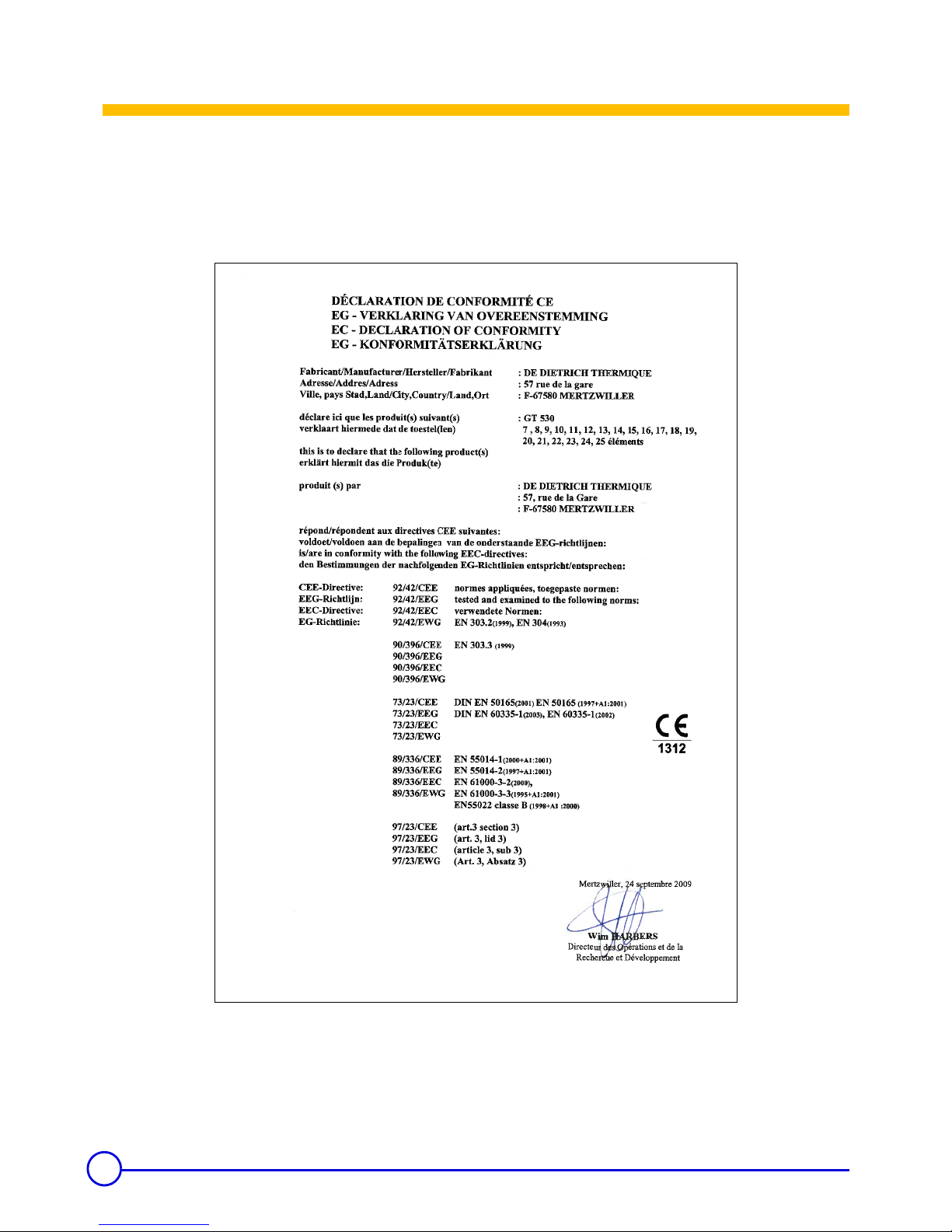
3.2.1 Standard control panel- S3
Standard panel to be fitted
Panel comprising the settings, control and safety devices allowing
the boiler to operate autonomously, without regulation.
The standard panel is used to connect the boiler to the boiler room
control cabinet.
This cabinet can be fitted with control units.
3.2.2 K3 control panel
Separate panel
Panel comprising the settings, control and safety devices allowing
the boiler to operate autonomously.
Control panel K3 also allows the boiler to be used as a secondary
boiler for installations with 2 to 10 boilers in cascade, one of which is
fitted with a "DIEMATIC-m3" control panel.
Side panel
A version of the K3 control panel with lateral attachment is also
available.
9
25/01/2012 - 300011906-001-D GT 530
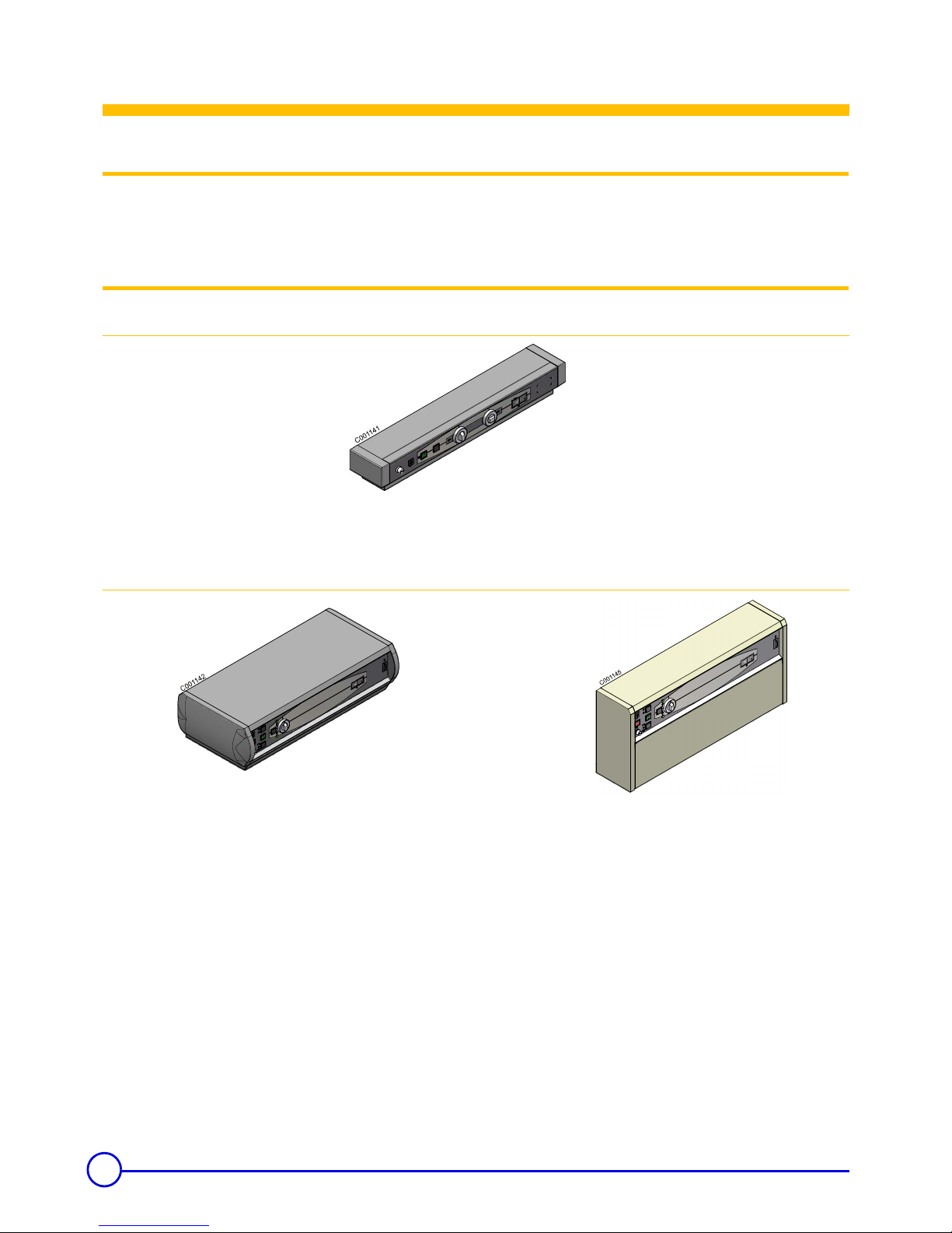
3.2.3 DIEMATIC-m3 control panel
Separate panel
Top of the range electronic control panel with digital display,
comprising the settings, control and safety devices allowing the boiler
to operate autonomously.
The DIEMATIC-m3 panel is fitted as standard with a control unit
which operates according to the outside temperature.
The DIEMATIC-m3 panel also allows the boiler to be used as a
master boiler for installations with 2 to 10 boilers in cascade.
The other boilers (1 to 9) must be fitted with a "K3" control panel.
Side panel
A version of the DIEMATIC-m3 control panel with lateral
attachment is also available.
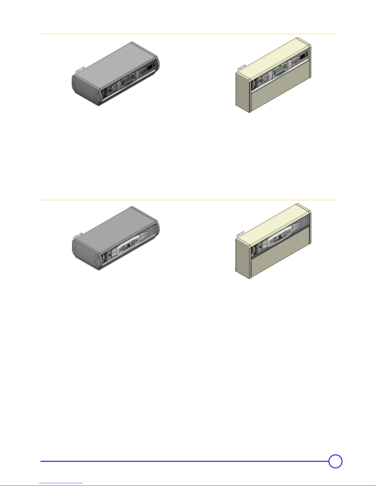
3.2.4 B3 control panel
Separate panel
Top of the range electronic control panel with digital display,
comprising the settings, control and safety devices allowing the boiler
to operate autonomously.
This panel makes it possible to give priority to DHW.
Side panel
A version of the B3 control panel with lateral attachment is also
available.
10
GT 530 25/01/2012 - 300011906-001-D
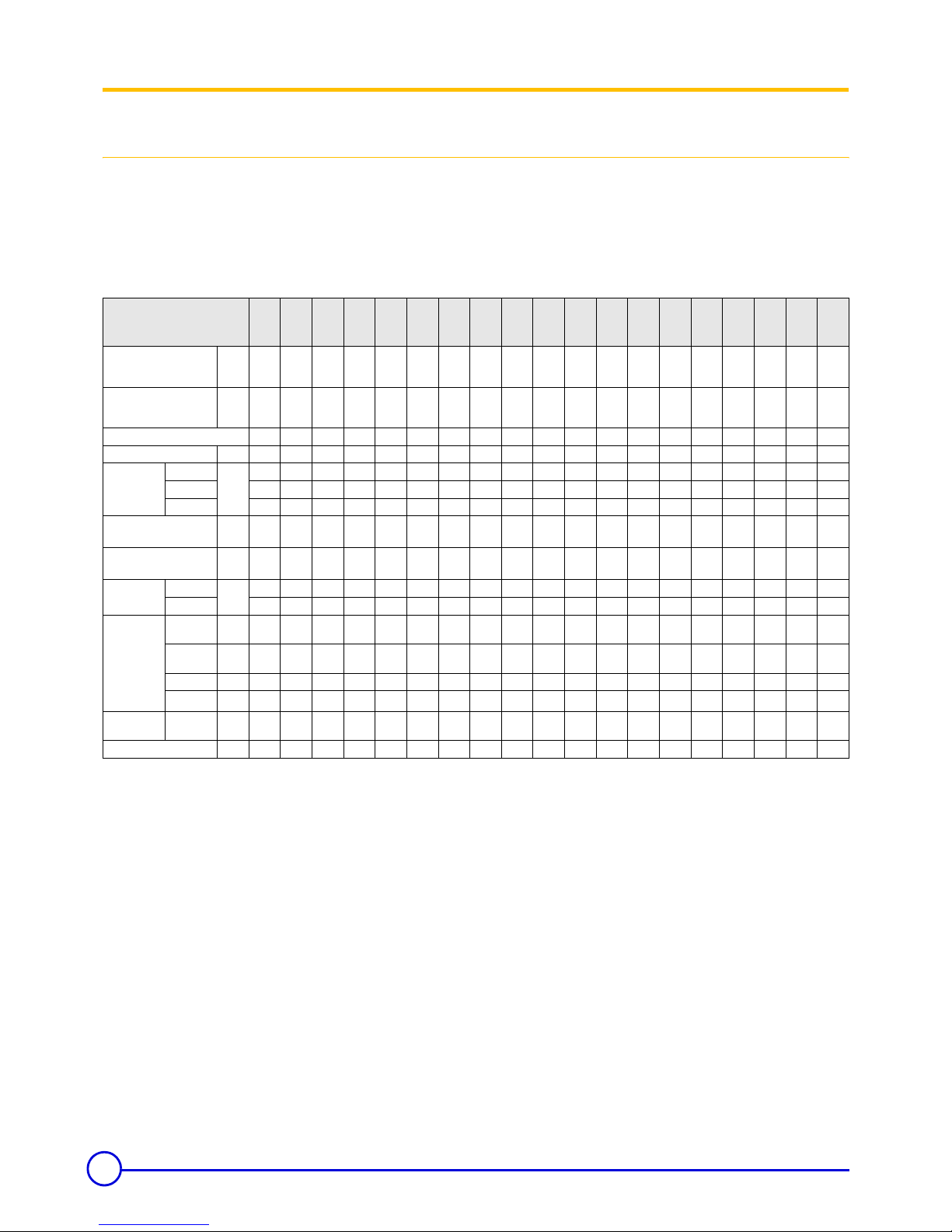
3.3 Technical specifications
3.3.1 Boilers for following countries: France, Algeria, Belgium, Bulgaria, China, Cyprus, Spain, Greece,
Luxemburg, Poland, Portugal, Czech Republic, Romania, Tunisia
Conditions of use:
Maximum operating pressure: 6 bar
Maximum operating temperature: 100 °C
Boiler thermostat setting: 30 to 90°C
Safety thermostat setting: 110 °C
*Maintenance consumption: total heat emission when the burner is
off as a percentage of the nominal input power when the difference
between the mean boiler temperature and the room temperature is
30 K - in accordance with DIN 4702 - EN 303.
Boiler
GT
530
-7
GT
530
-8
GT
530
-9
GT
530
-10
GT
530
-11
GT
530
-12
GT
530
-13
GT
530
-14
GT
530
-15
GT
530
-16
GT
530
-17
GT
530
-18
GT
530
-19
GT
530
-20
GT
530
-21
GT
530
-522
GT
530
-23
GT
530
-24
GT
530
-525
Useful output kW 348
to
406
406
to
464
464
to
522
522
to
580
580
to
638
638
to
696
696
to
754
754
to
812
812
to
870
870
to
928
928
to
986
986
to
1044
1044
to
1102
1102
to
1160
1160
to
1218
1218
to
1276
1276
to
1334
1334
to
1400
1400
to
1450
Power input kW 380
to
447
442
to
508
505
to
571
566
to
632
635
to
703
701
to
769
763
to
831
821
to
890
897
to
967
954
to
1024
1022
to
1093
1077t
o
1147
1146
to
1216
1198
to
1268
1265
to
1336
1333
to
1404
1393
to
1464
1463t
o
1544
1532
to
1595
Number of sections 7 8 9 10111213141516171819202122232425
Water content l 389 427 465 503 541 579 617 655 693 731 769 807 845 905 943 981 1019 1057 1095
Water
resistance
(1)
∆ T = 10K mbar 18 22 28.4 34.8 42 50 57.6 67.2 77.6 26.2 30.2 35.8 41.4 48.0 53.6 59.2 64.8 71.6 78.4
∆ T = 15K 8 9.9 12.6 15.5 18.7 22.4 25.8 30 34.7 11.7 13.5 14.0 18.5 21.5 24 26.5 29 32 35
∆ T = 20K 4.5 5.5 7.1 8.7 10.5 12.5 14.4 16.8 19.4 6.5 7.6 9.0 10.4 12.0 13.4 14.8 16.2 17.9 19.6
Pressure in the furnace for
nozzle pressure = 0
(4)
mbar
1.7 1.75 1.8 1.9 2 2.1 2.2 2.3 2.4 2.5 2.6 2.7 2.85 3 3.1 3.2 3.3 3.4 3.5
Flue gas temperature Ambient temperature
(1) (3)
K
<190 <190 <190 <190 <190 <190 <190 <190 <190 <190 <190 <190 <190 <190 <190 <190 <190 <190 <190
Mass flue gas
flow rate
(1) (2)
Fuel oil Kg/h 690 790 790 980 1080 1180 1380 1380 1480 1580 1670 1770 1870 1970 2070 2170 2260 2360 2460
Gas 720 830 930 1030 1140 1240 1340 1450 1550 1650 1760 1860 1960 2070 2170 2270 2380 2480 2580
Combustion
chamber
Inscribed
diameter
mm
614 614 614 614 614 614 614 614 614 614 614 614 614 614 614 614 614 614 614
Equivalent
diameter
mm
694 694 694 694 694 694 694 694 694 694 694 694 694 694 694 694 694 694 694
Depth mm 706 817 928 1039 1150 1261 1372 1483 1594 1705 1816 1927 2038 2189 2300 2411 2522 2633 2744
Volume
m
3
0.28 0.32 0.36 0.40 0.45 0.49 0.53 0.57 0.61 0.65 0.70 0.74 0.78 0.84 0.88 0.92 0.96 1.00 1.05
Maintenance
consumption*
∆ T = 30K
%
0.11 0.10 0.09 0.08 0.08 0.08 0.07 0.07 0.07 0.07 0.07 0.07 0.07 0.06 0.06 0.06 0.06 0.06 0.06
Weight (empty) kg 1852 2046 2237 2412 2601 2810 3000 3171 3364 3561 3756 3955 4124 4343 4538 4734 4930 5107 5297
(1) Nominal operation (top boiler power)
(2) CO
2
= 13.1 to 13.5% with fuel oil and 9.5% with natural gas.
(3) Boiler temperature: 80 °C
Ambient temperature: 20 °C
(4)
In order for the boiler to operate correctly, it is
imperative to respect the draught at the nozzle.
11
25/01/2012 - 300011906-001-D GT 530
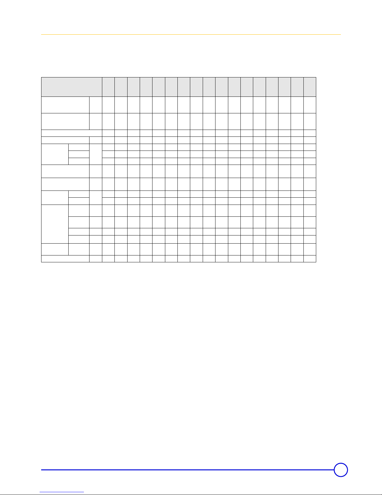
3.3.2 Boilers for following countries: Germany, Austria, Serbia, Slovenia
Conditions of use:
Maximum operating pressure: 6 bar
Maximum operating temperature: 100 °C
Maximum operating temperature: 120 °C
(in accordance with TRD 702)
Boiler thermostat setting: 30 to 90°C
Safety thermostat setting: 110 °C
*Maintenance consumption: total heat emission when the burner is
off as a percentage of the nominal input power when the difference
between the mean boiler temperature and the room temperature is
30 K - in accordance with DIN 4702 - EN303.
Boiler
GT
530
-9
GT
530
-10
GT
530
-11
GT
530
-12
GT
530
-13
GT
530
-14
GT
530
-15
GT
530
-16
GT
530
-17
GT
530
-18
GT
530
-19
GT
530
-20
GT
530
-21
GT
530
-522
GT
530
-23
GT
530
-24
GT
530
-525
Useful output kW 415
to
460
460
to
505
505
to
550
550
to
595
595
to
640
640
to
685
685
to
730
730
to
775
730
to
820
820
to
865
865
to
910
910
to
955
955
to
1000
1000
to
1045
1045
to
1090
1090
to
1135
1135
to
1180
Power input kW 448
to
500
494
to
546
547
to
599
597
to
649
643
to
696
689
to
741
743
to
797
790
to
842
790
to
892
886
to
938
935
to
987
982
to
1034
1034
to
1085
1082
to
1133
1131
to
1182
1180t
o
1231
1227
to
1278
Number of sections 9 10111213141516171819202122232425
Water content l 465 503 541 579 617 655 693 731 769 807 845 905 943 981 1019 1057 1095
Water
resistance
(1)
∆ T = 10K
mbar
22 25.9 30.5 37 43.5 50 55.8 21.8 24.2 26.8 30 33 35.6 38.9 42.9 45.6 48.9
∆ T = 15K 9.8 11.5 13.6 16.4 19.3 22.2 24.8 9.7 10.8 11.9 13.3 14.7 15.8 17.3 19.1 20.3 21.9
∆ T = 20K 5.5 6.9 8.1 9.2 10.6 12 13.9 4.5 5.8 6.5 7.2 7.9 8.6 9.4 1.6 11.8 12.4
Pressure in the furnace for
nozzle pressure = 0
(4)
mbar 1.4 1.45 1.5 1.55 1.6 1.65 1.7 1.75 1.8 1.85 1.95 2.05 2.1 2.15 2.2 2.25 2.3
Flue gas temperature Ambient temperature
(1) (3)
K <190 <190 <190 <190 <190 <190 <190 <190 <190 <190 <190 <190 <190 <190 <190 <190 <190
Mass flue gas
flow rate
(1) (2)
Fuel oil
Kg/h
770 850 920 1000 1070 1150 1220 1300 1370 1450 1520 1600 1670 1750 1820 1900 1970
Gas 810 890 970 1040 1120 1200 1280 1360 1440 1520 1590 1670 1750 1830 1910 1990 2070
Combustion
chamber
Inscribed
diameter
mm 614 614 614 614 614 614 614 614 614 614 614 614 614 614 614 614 614
Equivalent
diameter
mm 694 694 694 694 694 694 694 694 694 694 694 694 694 694 694 694 694
Depth mm 928 1039 1150 1261 1372 1483 1594 1705 1816 1927 2038 2189 2300 2411 2522 2633 2744
Volume
m
3
0.36 0.40 0.45 0.49 0.53 0.57 0.61 0.65 0.70 0.74 0.78 0.84 0.88 0.92 0.96 1.00 1.05
Maintenance
consumption*
∆ T = 30K % 0.16 0.15 0.14 0.13 0.13 0.12 0.12 0.11 0.11 0.11 0.11 0.11 0.11 0.11 0.11 0.10 0.10
Weight (empty) kg 2205 2391 2567 2771 2945 3120 3314 3494 3684 3872 4040 4266 4444 4639 4817 4994 5168
(1) Nominal operation (top boiler power)
(2) CO
2
= 13.1 to 13.5% with fuel oil and 9.5% with natural gas.
(3) Boiler temperature: 80 °C
Ambient temperature: 20 °C
(4)
In order for the boiler to operate correctly, it is
imperative to respect the draught at the nozzle.
12
GT 530 25/01/2012 - 300011906-001-D
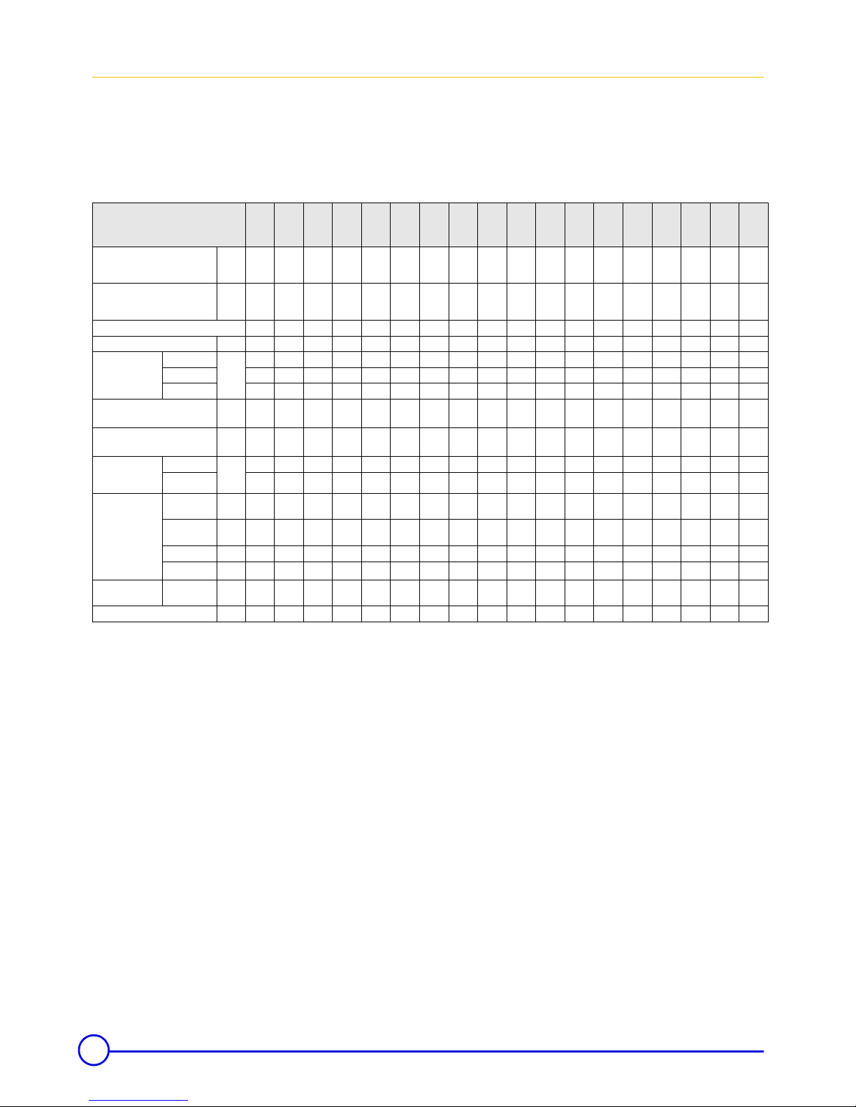
3.3.3 Boilers for following countries: Switzerland
Conditions of use:
Maximum operating pressure: 6 bar
Maximum operating temperature: 100 °C
Boiler thermostat setting: 30 to 90°C
Safety thermostat setting: 110 °C
*Maintenance consumption: total heat emission when the burner is
off as a percentage of the nominal input power when the difference
between the mean boiler temperature and the room temperature is
30 K - in accordance with DIN 4702 - EN 303.
Boiler
GT
530
-8
GT
530
-9
GT
530
-10
GT
530
-11
GT
530
-12
GT
530
-13
GT
530
-14
GT
530
-15
GT
530
-16
GT
530
-17
GT
530
-18
GT
530
-19
GT
530
-20
GT
530
-21
GT
530
-522
GT
530
-23
GT
530
-24
GT
530
-525
Useful output kW 250
to
365
275
to
395
300
to
435
330
to
470
360
to
510
390
to
550
420
to
580
440
to
620
470
to
660
495
to
690
530
to
730
550
to
770
580
to
810
610
to
840
640
to
880
670
to
920
690
to
960
720
to
1000
Power input kW 260
to
390
291
to
425
315
to
465
346
to
495
381
to
550
409
to
590
440
to
620
460
to
650
492
to
710
519
to
740
557
to
785
578
to
825
609
to
870
642
to
905
679
to
945
705
to
990
728
to
1030
764
to
1075
Number of sections 8 9 10 11 12 13 14 15 16 17 18 19 20 21 22 23 24 25
Water content l 427 465 503 541 579 617 655 693 731 769 807 845 905 943 981 1019 1057 1095
Water resistance
(1)
∆ T = 10K
mbar
13.9 15.8 19.1 23.1 27.6 32.2 35.2 40.3 15.7 17.1 19.3 21.5 23.4 25.1 28.0 30.2 32.1 37.0
∆ T = 15K 6.2 7 8.5 10.3 12.3 14.3 15.7 17.9 7 7.6 8.6 9.5 10.4 11.2 12.4 13.3 14.5 16.5
∆ T = 20K 3.5 4.2 5.1 5.7 6.7 7.7 8.8 10 3.8 4.1 4.6 5.1 5.6 6.1 7.6 7.8 8.2 9.3
Pressure in the furnace for nozzle
pressure = 0
(4)
mbar 1.05 1.05 1.1 1.1 1.15 1.2 1.2 1.25 1.3 1.3 1.35 1.4 1.5 1.5 1.55 1.6 1.6 1.65
Flue gas temperature - Ambient
temperature
(1) (3)
K <160 <160 <160 <160 <160 <160 <160 <160 <160 <160 <160 <160 <160 <160 <160 <160 <160 <160
Mass flue gas flow
rate
(1) (2)
Fuel oil kg
per
sec
0.160 0.174 0.191 0.203 0.226 0.242 0.254 0.267 0.291 0.304 0.322 0.339 0.357 0.371 0.388 0.406 0.423 0.441
Gas 0.174 0.190 0.207 0.221 0.245 0.263 0.276 0.290 0.316 0.330 0.350 0.367 0.388 0.403 0.421 0.441 0.459 0.479
Combustion
chamber
Inscribed
diameter
mm 614 614 614 614 614 614 614 614 614 614 614 614 614 614 614 614 614 614
Equivalent
diameter
mm 694 694 694 694 694 694 694 694 694 694 694 694 694 694 694 694 694 694
Depth mm 817 928 1039 1150 1261 1372 1483 1594 1705 1816 1927 2038 2189 2300 2411 2522 2633 2744
Volume
m
3
0.32 0.36 0.40 0.45 0.49 0.53 0.57 0.61 0.65 0.70 0.74 0.78 0.84 0.88 0.92 0.96 1.00 1.05
Maintenance
consumption*
∆ T = 30K % 0.13 0.12 0.12 0.11 0.11 0.11 0.11 0.10 0.10 0.10 0.10 0.10 0.10 0.09 0.09 0.09 0.09 0.09
Weight (empty) kg 2046 2237 2412 2601 2810 3000 3171 3364 3561 3756 3955 4124 4343 4538 4734 4930 5107 5297
(1) Nominal operation (top boiler power)
(2) CO
2
= 13.1 to 13.5% with fuel oil and 9.5% with natural gas.
(3) Boiler temperature: 80 °C
Ambient temperature: 20 °C
(4)
In order for the boiler to operate correctly, it is
imperative to respect the draught at the nozzle.
 Loading...