

DeDietrich GT 400 A Assembly And Installation Instructions Manual
82N529 09
2
1
GT 400 A
Fuel oil/gas hot water boiler
English
11/03/09
94863449
Assembly and installation instructions
Warning:
Before putting the boiler into operation read this manual
carefully.
Warning:
The operating manual is part of the documentation that is
delivered to the installation’s operator. Go through the
information in this manual with the owner/operator and
make sure that he or she is familiar with all the necessary
operating instructions.
Notice:
This manual must be retained for future reference. Improper
installation, adjustment, alteration, service or maintenance can
cause injury, loss of life or property damage. Refer to this
manual. For assistance or additional information consult a
qualified installer, service agency or the gas supplier.

2
GT 400 A 21/09/06 - 94863449 - 82294154E
Guideline of Notices
Warning:
indicates presence of hazards that can cause, if not
avoided, severe personal injury, death or substantial
property damage.
! Caution:
indicates presence of hazards that will or can cause, if not
avoided, minor personal injury or property damage.
Notice:
Application comment for optimum use of equipment and
adjustment as well as useful information.
Z
Reference to an other instruction book.
Observe the following symbols
DANGER
due to explosion of gas.
- Work only on gas components when you have a license to do so.
- Note that the assembly of gas and vent connections, the initial
start-up, the electrical connections, the maintenance and service
can only be performed by a licensed service contractor or
technician.
DANGER
due to electricity.
- Prior to doing any work on the heating system, disconnect all
electrical power to the boiler at the emergency switch.
- It is NOT sufficient to shut off only the boiler control!
! CAUTION!
SYSTEM DAMAGE
due to improper installation.
- Observe local and state codes as well as common industry
practices during the installation and operation of the heating
appliance.
! CAUTION!
SYSTEM DAMAGE
due to inadequate cleaning and maintenance.
- A boiler cleaning and maintenance should be performed annually.
Verify complete system operation at the same time.
- Correct the problem immediately to prevent damage to the
system!
! Caution:
Refer to User’s Manual regarding the carcinogenic hazard of
crystalline silica that may be found during installation, servicing
and removal of this boiler.
Safety Considerations
Please observe the following safety instructions.
Read this manual carefully.
Correct installation and adjustment of the burner and the control
panel is a precondition for safe, efficient operation of the gas boiler.
Read this manual and the specifications on the safety label carefully
before attempting to put the burner into operation.
Do not store or use gasoline or other flammable liquids in
the vicinity of this or any other appliance.
WHAT TO DO IF YOU SMELL GAS:
- Do not try to light any appliance.
- Do not touch any electric switch, do not use any phone in
your building.
- Immediately call your gas supplier from a neighbor’s
phone. Follow the gas supplier’s instructions.
- If you cannot reach your gas supplier, call the Fire
Department.
Installation and service must be performed by a qualified
installer, service agency or the gas supplier.
Warning:
Improper installation, adjustment, and/or operation could
cause carbon monoxide poisoning resulting in injury or
death.
This product must be installed and serviced by a
professional service technician who is experienced and
qualified in hot water boiler installation and gas
combustion.
! Caution: Strict compliance with these instructions is a
precondition for the correct operation of the boiler.
! IMPORTANT
Service on this boiler should be undertaken only by trained and
skilled personnel.
Keep boiler area clear and free from combustible materials,
gasoline and other flammable vapors and liquids.
Do not place any obstruction in the boiler room that will hinder
the flow of combustion and ventilating air.
Read these instructions carefully before proceeding with the
installation of boiler. Post instructions near boiler for reference
by owner and serviceman.
Maintain instructions in legible condition.

3
21/09/06 - 94863449 - 82294154E GT 400 A
Contents
Contents . . . . . . . . . . . . . . . . . . . . . . . . . . . . . . . . . . . . . . . . . . . . . . . . . . . . . . . . . . . . . . . . . . . . . . . . . . . . . . . . . . . .3
Regulations and guidelines . . . . . . . . . . . . . . . . . . . . . . . . . . . . . . . . . . . . . . . . . . . . . . . . . . . . . . . . . . . . . . . . . . . .4
General . . . . . . . . . . . . . . . . . . . . . . . . . . . . . . . . . . . . . . . . . . . . . . . . . . . . . . . . . . . . . . . . . . . . . . . . . . . . . . . . . . . . .4
1 Boilers covered by this document . . . . . . . . . . . . . . . . . . . . . . . . . . . . . . . . . . . . . . . . . . . . . . . . . . . . . . . . . . . . . . . . . . . . . . . . . . . . .4
2 Uncrating . . . . . . . . . . . . . . . . . . . . . . . . . . . . . . . . . . . . . . . . . . . . . . . . . . . . . . . . . . . . . . . . . . . . . . . . . . . . . . . . . . . . . . . . . . . . . . . .4
3 Packing. . . . . . . . . . . . . . . . . . . . . . . . . . . . . . . . . . . . . . . . . . . . . . . . . . . . . . . . . . . . . . . . . . . . . . . . . . . . . . . . . . . . . . . . . . . . . . . . . .5
4 Technical specifications of boilers . . . . . . . . . . . . . . . . . . . . . . . . . . . . . . . . . . . . . . . . . . . . . . . . . . . . . . . . . . . . . . . . . . . . . . . . . . . . .7
Main Dimensions . . . . . . . . . . . . . . . . . . . . . . . . . . . . . . . . . . . . . . . . . . . . . . . . . . . . . . . . . . . . . . . . . . . . . . . . . . . . .8
Boiler Installation. . . . . . . . . . . . . . . . . . . . . . . . . . . . . . . . . . . . . . . . . . . . . . . . . . . . . . . . . . . . . . . . . . . . . . . . . . . . .9
1 Installation . . . . . . . . . . . . . . . . . . . . . . . . . . . . . . . . . . . . . . . . . . . . . . . . . . . . . . . . . . . . . . . . . . . . . . . . . . . . . . . . . . . . . . . . . . . . . . .9
2 Ventilation. . . . . . . . . . . . . . . . . . . . . . . . . . . . . . . . . . . . . . . . . . . . . . . . . . . . . . . . . . . . . . . . . . . . . . . . . . . . . . . . . . . . . . . . . . . . . . .10
Assembly . . . . . . . . . . . . . . . . . . . . . . . . . . . . . . . . . . . . . . . . . . . . . . . . . . . . . . . . . . . . . . . . . . . . . . . . . . . . . . . . . .10
Piping . . . . . . . . . . . . . . . . . . . . . . . . . . . . . . . . . . . . . . . . . . . . . . . . . . . . . . . . . . . . . . . . . . . . . . . . . . . . . . . . . . . . .27
1 Dimensional information required. . . . . . . . . . . . . . . . . . . . . . . . . . . . . . . . . . . . . . . . . . . . . . . . . . . . . . . . . . . . . . . . . . . . . . . . . . . . .27
2 Recommendations . . . . . . . . . . . . . . . . . . . . . . . . . . . . . . . . . . . . . . . . . . . . . . . . . . . . . . . . . . . . . . . . . . . . . . . . . . . . . . . . . . . . . . . .27
3 Filling . . . . . . . . . . . . . . . . . . . . . . . . . . . . . . . . . . . . . . . . . . . . . . . . . . . . . . . . . . . . . . . . . . . . . . . . . . . . . . . . . . . . . . . . . . . . . . . . . .28
4 Ancillaries. . . . . . . . . . . . . . . . . . . . . . . . . . . . . . . . . . . . . . . . . . . . . . . . . . . . . . . . . . . . . . . . . . . . . . . . . . . . . . . . . . . . . . . . . . . . . . .28
Combustion and ventilation . . . . . . . . . . . . . . . . . . . . . . . . . . . . . . . . . . . . . . . . . . . . . . . . . . . . . . . . . . . . . . . . . . .30
1 Clearances. . . . . . . . . . . . . . . . . . . . . . . . . . . . . . . . . . . . . . . . . . . . . . . . . . . . . . . . . . . . . . . . . . . . . . . . . . . . . . . . . . . . . . . . . . . . . .30
2 Replacement procedures. . . . . . . . . . . . . . . . . . . . . . . . . . . . . . . . . . . . . . . . . . . . . . . . . . . . . . . . . . . . . . . . . . . . . . . . . . . . . . . . . . .31
3 Dimensional information required for connection of the boiler. . . . . . . . . . . . . . . . . . . . . . . . . . . . . . . . . . . . . . . . . . . . . . . . . . . . . . .31
Oil or gas connection . . . . . . . . . . . . . . . . . . . . . . . . . . . . . . . . . . . . . . . . . . . . . . . . . . . . . . . . . . . . . . . . . . . . . . . .32
1 Specific technical information supplied with the burner . . . . . . . . . . . . . . . . . . . . . . . . . . . . . . . . . . . . . . . . . . . . . . . . . . . . . . . . . . . .32
Electrical. . . . . . . . . . . . . . . . . . . . . . . . . . . . . . . . . . . . . . . . . . . . . . . . . . . . . . . . . . . . . . . . . . . . . . . . . . . . . . . . . . .33
1 Wiring. . . . . . . . . . . . . . . . . . . . . . . . . . . . . . . . . . . . . . . . . . . . . . . . . . . . . . . . . . . . . . . . . . . . . . . . . . . . . . . . . . . . . . . . . . . . . . . . . .33
2 Wiring procedure . . . . . . . . . . . . . . . . . . . . . . . . . . . . . . . . . . . . . . . . . . . . . . . . . . . . . . . . . . . . . . . . . . . . . . . . . . . . . . . . . . . . . . . . .33
3 Wiring boiler panel . . . . . . . . . . . . . . . . . . . . . . . . . . . . . . . . . . . . . . . . . . . . . . . . . . . . . . . . . . . . . . . . . . . . . . . . . . . . . . . . . . . . . . . .34
Start up procedures. . . . . . . . . . . . . . . . . . . . . . . . . . . . . . . . . . . . . . . . . . . . . . . . . . . . . . . . . . . . . . . . . . . . . . . . . .35
1 Shut-down procedures. . . . . . . . . . . . . . . . . . . . . . . . . . . . . . . . . . . . . . . . . . . . . . . . . . . . . . . . . . . . . . . . . . . . . . . . . . . . . . . . . . . . .36
Maintenance . . . . . . . . . . . . . . . . . . . . . . . . . . . . . . . . . . . . . . . . . . . . . . . . . . . . . . . . . . . . . . . . . . . . . . . . . . . . . . . .37
1 Boiler . . . . . . . . . . . . . . . . . . . . . . . . . . . . . . . . . . . . . . . . . . . . . . . . . . . . . . . . . . . . . . . . . . . . . . . . . . . . . . . . . . . . . . . . . . . . . . . . . .37
2 Shut down procedure. . . . . . . . . . . . . . . . . . . . . . . . . . . . . . . . . . . . . . . . . . . . . . . . . . . . . . . . . . . . . . . . . . . . . . . . . . . . . . . . . . . . . .38
Service and maintenance schedule . . . . . . . . . . . . . . . . . . . . . . . . . . . . . . . . . . . . . . . . . . . . . . . . . . . . . . . . . . . . .39
Isometric views and list of spare parts - GT 400 A. . . . . . . . . . . . . . . . . . . . . . . . . . . . . . . . . . . . . . . . . . . . . . . . .40

4
GT 400 A 21/09/06 - 94863449 - 82294154E
Regulations and guidelines
The installation and operating instructions shown here are given as a
guide for installation and operation and are not meant to replace any
State or Local Codes that may apply to the individual installation.
Good engineering practice should be used. Any deviation from laws
or regulations or industry Code or these instructions will void the
boiler warranty and any other responsability or liability of the De
Dietrich Thermiques S.A.
Installation codes
• THE BOILER SHALL BE ASSEMBLED AND INSTALLED BY A
QUALIFIED PROFESSIONAL ONLY. STRICT COMPLIANCE WITH
THESE INSTALLATION AND OPERATING INSTRUCTIONS IS A
PRECONDITION FOR THE CORRECT AND GUARANTEE OF THE
BOILER.
• THE INSTALLATION MUST CONFORM TO THE
REQUIREMENTS OF THE AUTHORITY HAVING JURISTRICTION
OR, IN THE ABSENCE OF SUCH REQUIREMENTS, TO THE CAN/
CGA B-149 FUEL GAS INSTALLATION CODES AND CSA B-139
OIL INSTALLATION CODES.
• WHERE REQUIRED BY THE AUTHORITY HAVING
JURISTRICTION, THE INSTALLATION MUST CONFORM TO THE
STANDARD FOR CONTROLS AND SAFETY DEVICES FOR
AUTOMATICALLY FIRED BOILERS ANSI/ASME CSD-1.
• THE INSTALLATION OF THE RELIEF VALVE SHALL BE
CONSISTENT WITH ANSI/ASME BOILER PRESSURE VESSEL
CODE, SECTION IV CSA B51.
• THE BOILER MUST NOT BE INSTALLED ON CARPETING.
• IF AN EXTERNAL ELECTRICAL SOURCE IS UTILIZED, THE
BOILER WHEN INSTALLED, MUST BE ELECTRICALLY BONDED
TO GROUND IN ACCORDANCE WITH THE REQUIREMENTS OF
THE AUTHORITY HAVING JURISTRICTION OR, IN THE
ABSENCE OF SUCH REQUIREMENTS, WITH THE CANADIAN
ELECTRICAL CODE PART 1, CSA C22.1, ELECTRICAL CODE.
LABEL ALL WIRES PRIOR TO DISCONNECTION WHEN
SERVICING CONTROLS. WIRING CAN CAUSE IMPROPER
OPERATION AFTER SERVICINGS. “VERIFY PROPER
OPERATION AFTER SERVICE”.
General
The boilers of the GT400 A range are automatic independent hotwater boilers designed for connecting to a flue which require a
separate fuel oil or gas burner.
1 Boilers covered by this document
The GT 400 A boilers are pressurized hot water heating boilers,
connected to a flue, fitted with an independent burner using domestic
fuel oil or gas.
The boiler is equipped with standard control panel.
2 Uncrating
Upon arrival, check shipment to ensure all parts have been shipped.
Inspect all items for delivery damage. Report all damage and
shortages to the delivery carrier. Report any damage and shortages
to the Distributor.

5
21/09/06 - 94863449 - 82294154E GT 400 A
3 Packing
Before installing the boiler, check the chart below to ensure you have
all the components.
ITEM Box nr. GT 408A GT 409A GT 410A GT 411A GT 412A GT 413A GT 414A
Underframe (dimensions according to model) 1111111
Front section 1111111
Normal intermediate section 567891011
Special intermediate section 1111111
Rear section 1111111
Common accessories CS 20 1111111
Accessories (composition according to model) 1111111
Baffles
CS 30 1
CS 31 11
CS 34 1
CS 35 11
CS 36 1
Inner body insulation
CS 51 1
CS 53 11
CS 55 11
CS 57 11
Casing : common parts
CS 428 1
CS 429 1
CS 430 1
CS 431 1
CS 432 1
CS 433 1
CS 434 1
Casing : varying parts
CS 11 11
CS 12 111
CS 13 111222
CS 14 11
Wiring ducts
CS 41 1
CS 42 1
CS 43 1
CS 44 1
CS 45 1
CS 46 1
CS 47 1
Standard control panel FA 122 1111111

6
GT 400 A 21/09/06 - 94863449 - 82294154E
Technical documents
CS 418 1
CS 419 1
CS 420 1
CS 421 1
CS 422 1
CS 423 1
CS 424 1
ITEM Box nr. GT 408A GT 409A GT 410A GT 411A GT 412A GT 413A GT 414A

7
21/09/06 - 94863449 - 82294154E GT 400 A
4 Technical specifications of boilers
- CSA - MBH Output based on Thermal Efficiency Test According to
ANSI Z21.13a/CSA 4.9a-2005
- [NET] MBH Output Factor 1.15, Allowance for Piping and Pickup
Losses
- Chamber Resistance Based on Neutral Chimney-Vent Pressure
- Gas Vent Category Based on Several Factors [CO2 content, Vent
Pressure & Net-Flue Gas Temp]
- Approved for Direct-Vent, Use Only Approved Venting as Listed
- Natural Draft Applications, Approved for Type L vent [Gas-Oil] or
Type B Vent [Gas Only]
- Conversion Btu to kW = 3,412 Btu per kW
- All Models are Design Certified & Eligible to Bear Approval Marking
as Shown.
- All Models Certified to Fire; # 2 oil, Natural & Propane Gases.
Consult factory for Available Burners.
- All Models Comply and Certified in Accordance to the latest
Canadian & US standards
- To Obtain Current IBR Ratings, consult their publications and
website.
Item Unit GT 408 A GT 409 A GT 410 A GT 411 A GT 412 A GT 413 A GT 414 A
Firing Sequence Consult Burner Technical Data
[CSA] - Gas Input
MBH 1730 1947 2278 2567 2826 3100 3389
kW 507.0 570.5 667.6 752.3 828.3 908.6 993.3
[CSA] - # 2 Fuel Oil Input US GPH 12.00 13.50 15.80 17.80 19.60 21.50 23.50
[CSA] - Output [Gas-Oil]
MBH 1471 1655 1937 2182 2402 2635 2880
kW 431.1 485.0 567.6 639.4 704.1 772.3 844.2
[NET] - Output [Gas-Oil] MBH 1279 1439 1684 1897 2089 2292 2505
Cast Iron sections # 8 9 10 11 12 13 14
Flue-way baffles #16161624202020
Water capacity
US Gal 96.72 108.08 119.45 130.81 142.17 153.54 164.90
Liter 366 409 452 495 538 581 624
Water resistance
[
∆t = °F]
18° F
Ft. H
2
O
1.24 1.84 2.88 3.51 4.55 5.39 6.82
27° F
Ft. H
2
O
0.669 0.903 1.24 1.57 2.09 2.63 3.68
36° F
Ft. H
2
O
0.318 0.452 0.753 0.903 1.12 1.34 1.81
Combustion chamber
Dimensions
Diameter
[equivalent]
Inch 20.87
mm 530
Depth
Inch 46.57 52.87 59.17 65.47 71.77 78.07 84.87
mm 1183 1343 1503 1663 1823 1983 2143
Volume
ft
3
10.95 12.50 13.98 15.50 16.99 18.47 19.95
m
3
0.31 0.354 0.396 0.439 0.481 0.523 0.565
MAWP [Water] PSI ASME IV Rating Class 30 - (90 PSI) [See Canadian Provincial CRN approvals]
Min. Safety Relief Capacity MBH 1471 1655 1937 2182 2402 2635 2880
FA 122 Panel
Electrical connection V/P/H 120/1/60
Max. Water Temp. Safety
Limit [MR]
°F 248
°C 120
Operating Water
Temperature Range
°F 86 - 185
°C 30 - 85
Chamber resistance
Inch w.c. 0.44 0.60 0.80 1.00 1.00 1.00 1.00
mbar
1.1 1.5 2 2.5 2.5 2.5 2.5
Gas-Vent Category # I, II - III or IV
Boiler Vent Connection Inch 10 10 10 12 12 12 12
Weight [Dry]
lb 3241 3638 4034 4431 4828 5225 5622
kg 1470 1650 1830 2010 2190 2370 2550
8
GT 400 A 21/09/06 - 94863449 - 82294154E
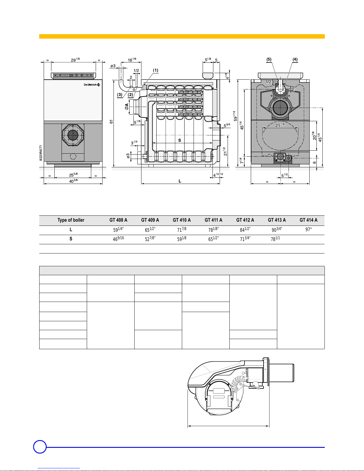
Main Dimensions
GT 400 A
(1) 3” 150# weld neck flange
(2) 1/2” NPT tapping for temp sensing well, etc…
(3) 2” NPT tapping for safety relief valve
(4) 3/4” NPT tapping for low water cutoff probe type
(5) 1/2” NPT tapping for combination pres/temp gauge
Notes:
-Dimension are for gas burners only
-Oil and combination oil/gas burner, refer to burner manufacturer
specifications
2
25
1/8
L
==
S
¯
A
==
==
6
20
7/8
5
1/2
5
3/4
4
15/16
40
3/8
25
5/8
3
1/4
¿3
61
5
1/8
16
1/8
5
1/8
5
¿3
1/2
29
1/8
25
1/8
45
1/4
7
1/4
21
1/2
45
1/4
59
1/16
4
1/8
8229N071
2
2
1/2
0
I
6A
(4)(5)
(1)
(3) (2)
Type of boiler GT 408 A GT 409 A GT 410 A GT 411 A GT 412 A GT 413 A GT 414 A
L
59
1/4"
65
1/2"
71
7/8
78
1/8"
84
1/2"
90
3/4"
97"
S
46
9/16
52
7/8"
59
1/8
65
1/2"
71
3/4"
78
1/16"
84
3/8"
Ø A out.
9
7/8
9
7/8
9
7/8
11
13/16"
11
13/16"
11
13/16"
11
13/16"
Dimension "X" Maximum Burner Length (inches)
Boiler Model Riello Weishaupt Power flame Fuel Master Gordon Piatt
GT408A
22
13/16
23
26
32
1/2
26
GT409A 32
GT410A
33
1/16
31
3/16
25
1/8
GT411A
30
1/8
GT412A
GT413A
37
7/16
35
GT414A
38
1/2
G50_0001
X
9
21/09/06 - 94863449 - 82294154E GT 400 A
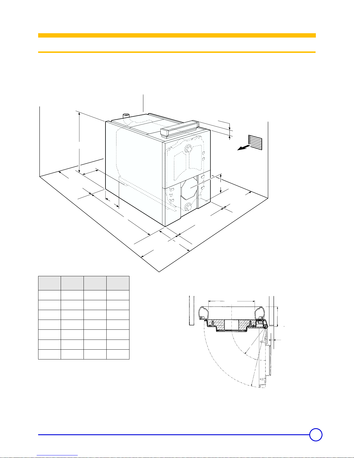
Boiler Installation
1Installation
The GT 400 A boiler has a sturdy underframe, it does not need any
special base although a housekeeping pad is recommended to keep
steel parts out of casual water. Its furnace is closed, so it is not
necessary to place it on a fireproof floor, but the floor must be able to
bear the weight.
Additional
the space required when the burner door is open.
Top view
Burner door open
Combustion air
per local codes
21 1/2"
59
1/16"
4
1/8
"
40
1/8
"
7
1/8
"
20
3/8
"
40
3/8
"
20
3/8
"
B
L
X
S
Dimension LDimension BDimension
C
GT 408 A
59
1/4"
5
3/8"
24"
GT 409 A
65
1/2"
1
5/8"
71"
GT 410 A
71
7/8"
4
1/8"
71"
GT 411 A
78
1/8"
1
5/8"
71"
GT 412 A
84
1/2"
4
1/8"
76"
GT 413 A
90
3/4"
1
5/8"
76"
GT 414 A 97"
4
1/8"
76"
25 1/8"
R = 17"
R = 30
5/8
"
5/8"
10 1/8"
10
GT 400 A 21/09/06 - 94863449 - 82294154E
2 Combustion Air Supply
Boilers operating in atmospheres that contain fluorides or chlorides
such as beauty shops and automotive repair garages where air
conditioning services are performed or industrial applications that
may have corrosive elements in the air must have a clean source of
combustion and ventilation air. Boiler damage by contaminants will
void the warranty and any other responsibility or liability of De Dietrich
Thermique/FES Ltd.
Note: Ensure boiler room is adequately ventilated and clear
and free from combustible materials, gasoline and other
flammable vapours and liquids.
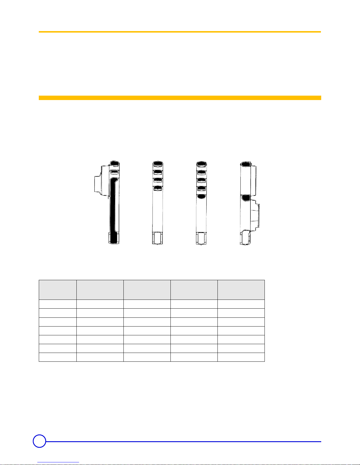
Assembly
To fit the sections, proceed in the following order :
- fit the rear section
- fit the special intermediate section
-fit all of the normal intermediate sections
- fit the front section
.
1: rear
2: front
8229 025AN
1
2
8229-0043
8229-0045
8229-0041 8229-0042
Boiler model
Rear section
n° 8229-0043
Special intermediate
section
8229-0045
Normal intermediate
section
8229-0041
Front section
8229-0042
GT 408 A 1 1 5 1
GT 409 A 1 1 6 1
GT 410 A 1 1 7 1
GT 411 A 1 1 8 1
GT 412 A 1 1 9 1
GT 413 A1 1101
GT 414 A1 1111
11
21/09/06 - 94863449 - 82294154E GT 400 A
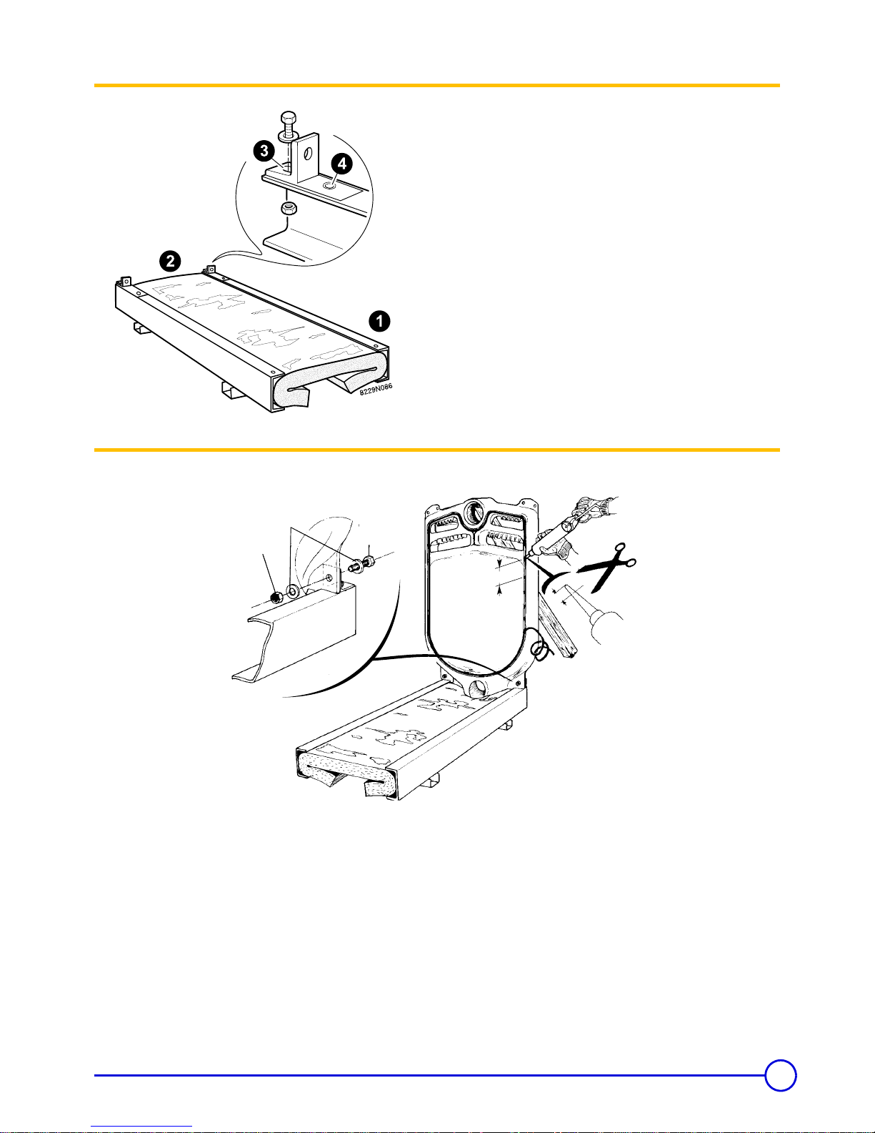
Step one
Front - Rear
GT 408 - GT 410 - GT 412 - GT 414
GT 409 - GT 411 - GT 413
- Fit the 2 rear attachment brackets (in the body accessories pack)
and attach them onto the framework using 2 bolts HM 12X25/25 +
4 washers L12 and 2 nuts HM 12.
Use the corresponding holes following the indication on
the frame.
- Put the lower insulation in place (fabric to the top) packs CS 51 to
CS 57. Adapt length if necessary or fold the lower insulation after
the casing has been completely assembled.
Step two
Mounting of framework and thermocord
• Locate the framework depending on the direction in which the
burner door will be opened and the length of the burner.
• Put the rear section in position on the framework and support it.
Attach it at the brackets using 2 bolts HM 12x40/40 + 4 washers
L 12 + 2 nuts HM 12.
• Using a silicone gun, put silicone mastic points (1 cartridge
supplied with the accessory pack CS 20) into the sealing
groove of the section (approx. every 5 to 10 cm) then carefully
put the thermocord in place in the sealing groove.
do not pull on the cord when it is being put in, to avoid
stretching to preserve its thickness. Avoid to locate the
junction point at the bottom of the section.
HM 12
40x40
HM 12
L 12
2/5"
8"
12
GT 400 A 21/09/06 - 94863449 - 82294154E
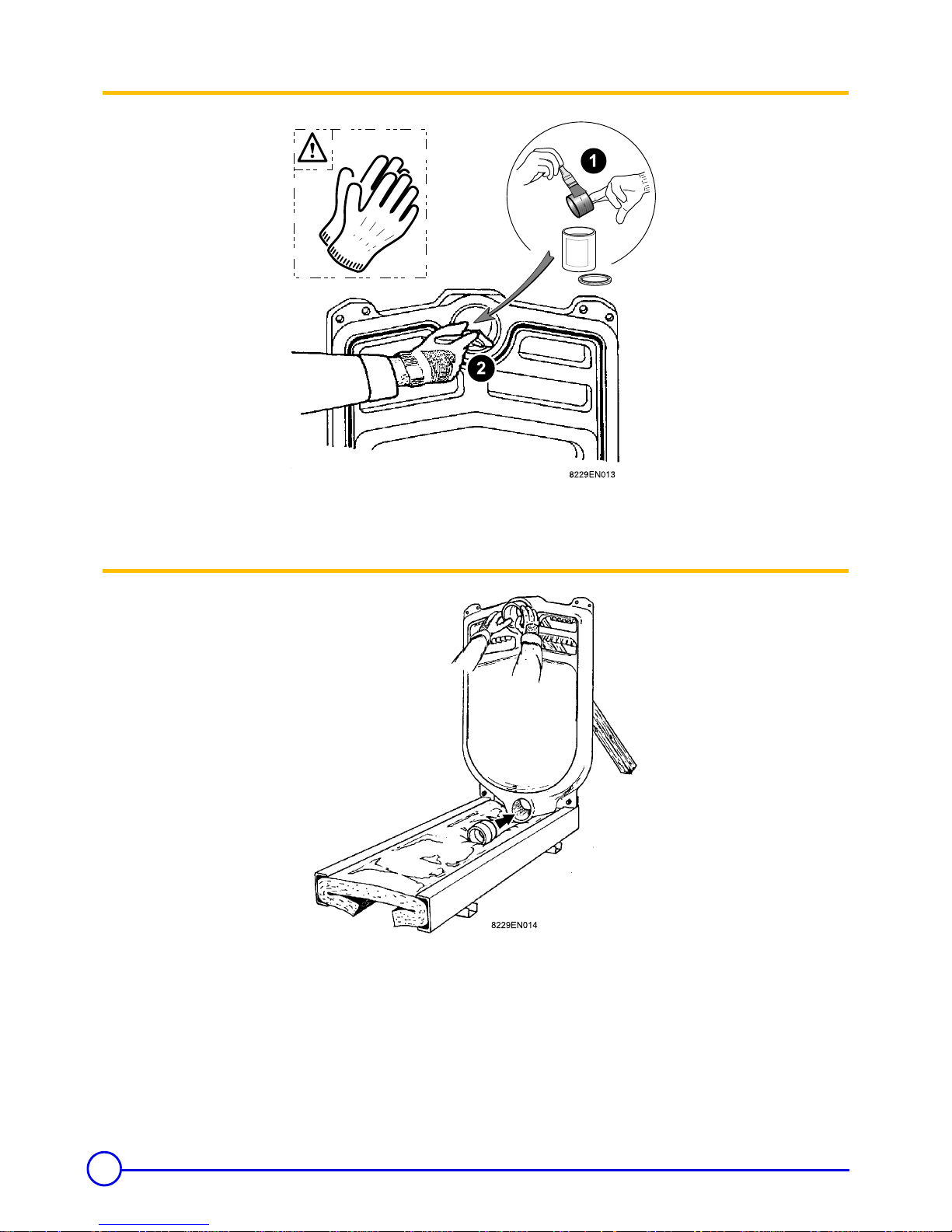
Step three
Handle the nipples with gloves, there might be sharp
edges.
Clean the bores and nipples with a solvent.
Coat them with the lubricant supplied with the sections.
Step four
- Drive in the 2 nipples gently.
13
21/09/06 - 94863449 - 82294154E GT 400 A
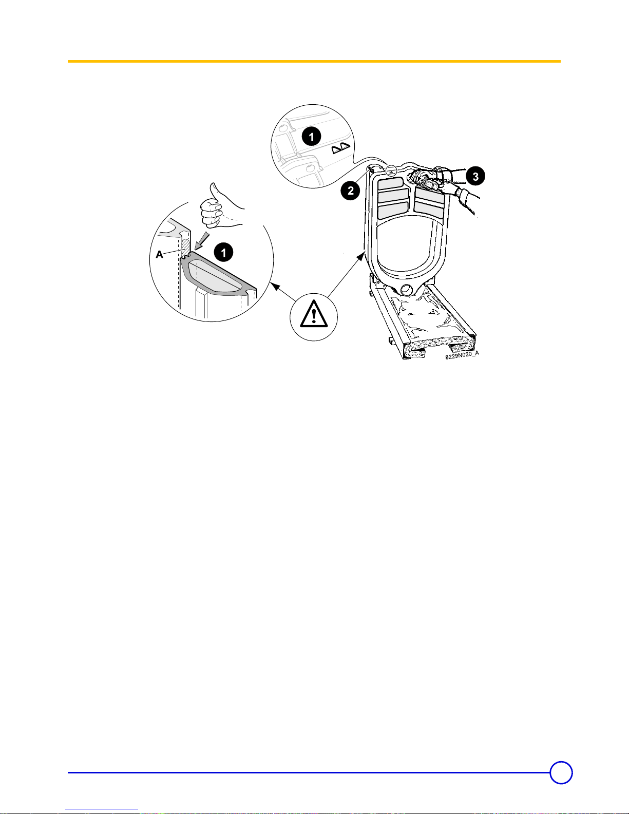
Step five
Assembling the sections
A : thermocord
Special intermediate section before rear section.
Place the special intermediate section, note front back
relationship with the sealing groove against the thermocord.
For safety, insert an upper assembly rod (body accessories
pack) into the holes in the 2 sections.
Gently and at the same time drive in the 2 nipples of the rear
section using a hammer and a piece of wood.
14
GT 400 A 21/09/06 - 94863449 - 82294154E
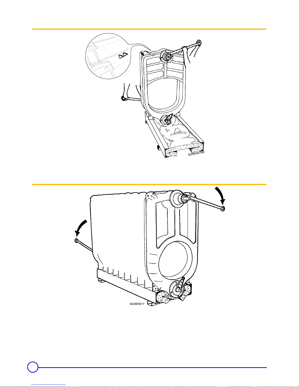
Step six
- Put the special assembly tool in place. - Tighten progressively so the upper and lower connections come
together equally at the same time.
Step seven
- Fit the remaining sections one by one in the order given,
proceeding as per steps 3-4-5-6.
- Leave the assembly tool in place.
15
21/09/06 - 94863449 - 82294154E GT 400 A
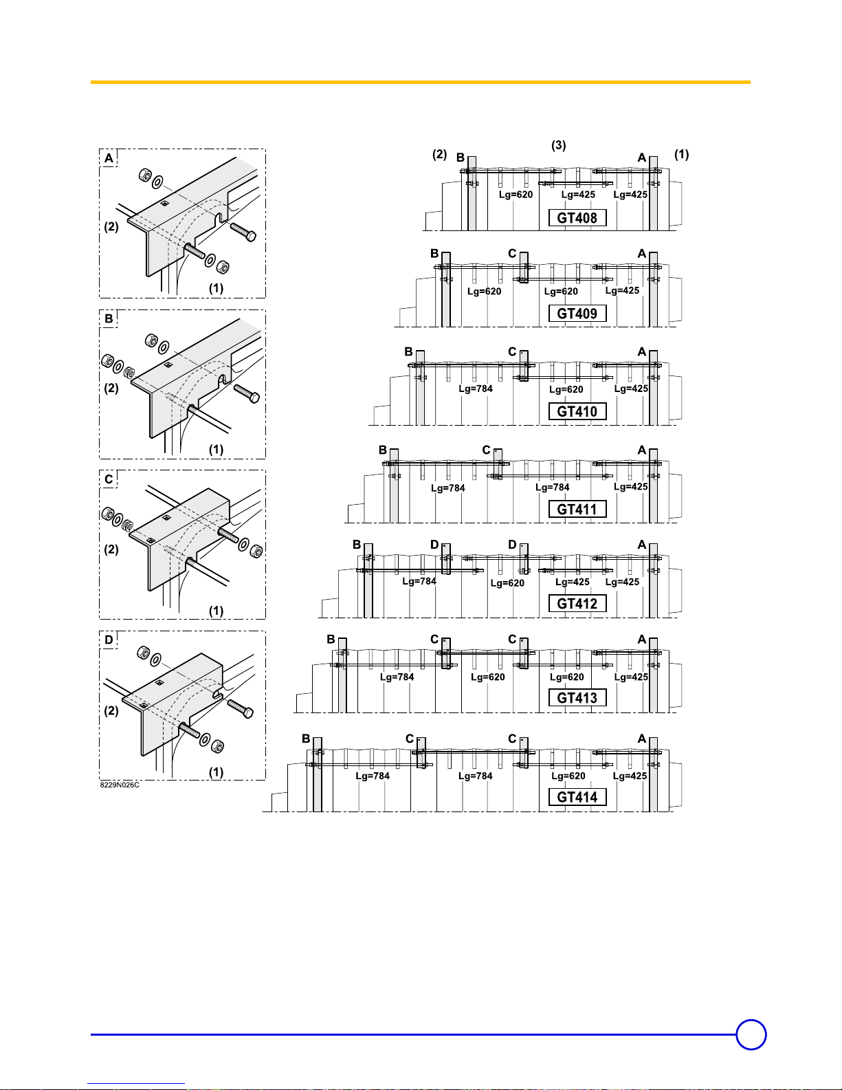
Step eight
Installing the assembly rods and upper casing supports
(1) Front - (2) Rear - (3) Top view
- Install the upper assembly rods (body accessories pack) in the
order given in the figure above. Place the expansion spring and its
washer on each rod towards the rear. Stop tightening the nuts
when the free space between the threads is about 1/16" to 1/
8".
- Install the upper casing supports (pack CS13) and the upper cross-
pieces (packs CS428 to CS434 and CS11 to CS14) with the
assembly rods (body accessories pack) as shown in details A-B-
C-D.
- Install the lower assembly rods in the order given in the figure.
- Remove the assembly tool.
16
GT 400 A 21/09/06 - 94863449 - 82294154E
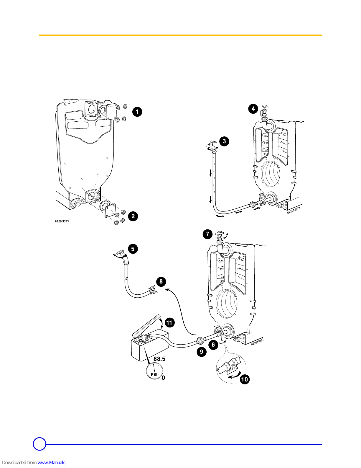
Step nine
Hydraulic test
After assembling the boiler body, the installer must carry
out a water tightness test at a pressure equal to 1.5 times
the operating pressure (that is 137 PSI minimum - 113 PSI
in Alberta) for 30 minutes at least. The test must be done at
room temperature.
Any drop in pressure indicates a leakage in the boiler body.
Ensure that all the air in the boiler is vented to avoid any bursting of the body.
After the tightness test, drain the boiler and remove all the parts used for the test.
8229N081
7
PSI
88.5
0
7
5
8
11
9
10
6
6
 Loading...