

DeDietrich GT 224, GT 225, GT 226, GT 227, GT 228 Installation And Service Manual
GT 220 - GT 2200
Fuel oil/gas-fired boilers
Installation and
Service Manual
300008281-001-E
EN
2
GT 220 - GT 2200 22/01/09 - 300008281-001-E
.
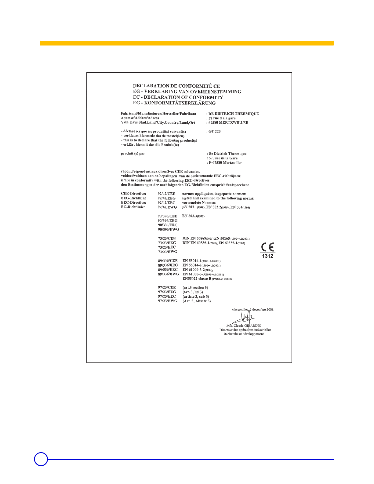
Declaration of conformity CE
C002209-A

3
22/01/09 - 300008281-001-E GT 220 - GT 2200
.
Contents
1 General . . . . . . . . . . . . . . . . . . . . . . . . . . . . . . . . . . . . . . . . . . . . . . . . . . . . . . . . . . . . . . . . . . . . . . . . . . . . . . . . .4
1.1 Regulations for France . . . . . . . . . . . . . . . . . . . . . . . . . . . . . . . . . . . . . . . . . . . . . . . . . . . . . . . . . . . . . . . . . . . . . . . . . . . . . . . . . . . .4
1.2 Regulations for other countries. . . . . . . . . . . . . . . . . . . . . . . . . . . . . . . . . . . . . . . . . . . . . . . . . . . . . . . . . . . . . . . . . . . . . . . . . . . . . .4
2 Description. . . . . . . . . . . . . . . . . . . . . . . . . . . . . . . . . . . . . . . . . . . . . . . . . . . . . . . . . . . . . . . . . . . . . . . . . . . . . .5
2.1 General. . . . . . . . . . . . . . . . . . . . . . . . . . . . . . . . . . . . . . . . . . . . . . . . . . . . . . . . . . . . . . . . . . . . . . . . . . . . . . . . . . . . . . . . . . . . . . . .5
2.2 Composition of the range . . . . . . . . . . . . . . . . . . . . . . . . . . . . . . . . . . . . . . . . . . . . . . . . . . . . . . . . . . . . . . . . . . . . . . . . . . . . . . . . . .5
2.3 Homologations . . . . . . . . . . . . . . . . . . . . . . . . . . . . . . . . . . . . . . . . . . . . . . . . . . . . . . . . . . . . . . . . . . . . . . . . . . . . . . . . . . . . . . . . . .5
2.4 Technical characteristics . . . . . . . . . . . . . . . . . . . . . . . . . . . . . . . . . . . . . . . . . . . . . . . . . . . . . . . . . . . . . . . . . . . . . . . . . . . . . . . . . .6
2.5 Rating plate . . . . . . . . . . . . . . . . . . . . . . . . . . . . . . . . . . . . . . . . . . . . . . . . . . . . . . . . . . . . . . . . . . . . . . . . . . . . . . . . . . . . . . . . . . . .7
2.6 Main dimensions. . . . . . . . . . . . . . . . . . . . . . . . . . . . . . . . . . . . . . . . . . . . . . . . . . . . . . . . . . . . . . . . . . . . . . . . . . . . . . . . . . . . . . . . .8
2.6.1 Boiler and tank dimensions . . . . . . . . . . . . . . . . . . . . . . . . . . . . . . . . . . . . . . . . . . . . . . . . . . . . . . . . . . . . . . . . . . . . . . . . . .8
2.6.2 Installation dimensions. . . . . . . . . . . . . . . . . . . . . . . . . . . . . . . . . . . . . . . . . . . . . . . . . . . . . . . . . . . . . . . . . . . . . . . . . . . . . .9
2.7 Aeration . . . . . . . . . . . . . . . . . . . . . . . . . . . . . . . . . . . . . . . . . . . . . . . . . . . . . . . . . . . . . . . . . . . . . . . . . . . . . . . . . . . . . . . . . . . . . .10
2.7.1 If using fuel oil . . . . . . . . . . . . . . . . . . . . . . . . . . . . . . . . . . . . . . . . . . . . . . . . . . . . . . . . . . . . . . . . . . . . . . . . . . . . . . . . . . .10
2.7.2 If using gas (GT 220 fitted with a forced draught gas-fired burner) . . . . . . . . . . . . . . . . . . . . . . . . . . . . . . . . . . . . . . . . . . .10
3 Installation . . . . . . . . . . . . . . . . . . . . . . . . . . . . . . . . . . . . . . . . . . . . . . . . . . . . . . . . . . . . . . . . . . . . . . . . . . . . .11
3.1 Mounting. . . . . . . . . . . . . . . . . . . . . . . . . . . . . . . . . . . . . . . . . . . . . . . . . . . . . . . . . . . . . . . . . . . . . . . . . . . . . . . . . . . . . . . . . . . . . .11
3.2 Hydraulic connections . . . . . . . . . . . . . . . . . . . . . . . . . . . . . . . . . . . . . . . . . . . . . . . . . . . . . . . . . . . . . . . . . . . . . . . . . . . . . . . . . . .11
3.3 Chimney connection . . . . . . . . . . . . . . . . . . . . . . . . . . . . . . . . . . . . . . . . . . . . . . . . . . . . . . . . . . . . . . . . . . . . . . . . . . . . . . . . . . . . .17
3.4 Connecting the burner . . . . . . . . . . . . . . . . . . . . . . . . . . . . . . . . . . . . . . . . . . . . . . . . . . . . . . . . . . . . . . . . . . . . . . . . . . . . . . . . . . .18
3.5 Electrical connections. . . . . . . . . . . . . . . . . . . . . . . . . . . . . . . . . . . . . . . . . . . . . . . . . . . . . . . . . . . . . . . . . . . . . . . . . . . . . . . . . . . .18
3.6 Filling the installation with water . . . . . . . . . . . . . . . . . . . . . . . . . . . . . . . . . . . . . . . . . . . . . . . . . . . . . . . . . . . . . . . . . . . . . . . . . . . .19
3.7 Commissioning . . . . . . . . . . . . . . . . . . . . . . . . . . . . . . . . . . . . . . . . . . . . . . . . . . . . . . . . . . . . . . . . . . . . . . . . . . . . . . . . . . . . . . . . .19
4 Maintenance. . . . . . . . . . . . . . . . . . . . . . . . . . . . . . . . . . . . . . . . . . . . . . . . . . . . . . . . . . . . . . . . . . . . . . . . . . . .20
4.1 Checking and cleaning the main components . . . . . . . . . . . . . . . . . . . . . . . . . . . . . . . . . . . . . . . . . . . . . . . . . . . . . . . . . . . . . . . . .20
4.2 Boiler . . . . . . . . . . . . . . . . . . . . . . . . . . . . . . . . . . . . . . . . . . . . . . . . . . . . . . . . . . . . . . . . . . . . . . . . . . . . . . . . . . . . . . . . . . . . . . . .20
4.3 Burner. . . . . . . . . . . . . . . . . . . . . . . . . . . . . . . . . . . . . . . . . . . . . . . . . . . . . . . . . . . . . . . . . . . . . . . . . . . . . . . . . . . . . . . . . . . . . . . .23
4.4 Domestic hot water tank . . . . . . . . . . . . . . . . . . . . . . . . . . . . . . . . . . . . . . . . . . . . . . . . . . . . . . . . . . . . . . . . . . . . . . . . . . . . . . . . . .23
5 Stopping the boiler . . . . . . . . . . . . . . . . . . . . . . . . . . . . . . . . . . . . . . . . . . . . . . . . . . . . . . . . . . . . . . . . . . . . . .24
6 Spare parts - GT 220 - GT 2200 . . . . . . . . . . . . . . . . . . . . . . . . . . . . . . . . . . . . . . . . . . . . . . . . . . . . . . . . . . . .25
Used symbols
Caution danger
Risk of injury and damage to equipment. Attention must be paid to the warnings on
safety of persons and equipment
Specific information Information must be kept in mind to maintain comfort
Z
Reference Refer to another manual or other pages in this instruction manual

4
GT 220 - GT 2200 22/01/09 - 300008281-001-E
1. General
1 General
The boiler shall be assembled and installed by a qualified
professional only. For a proper operating of the boiler,
follow carefully the instructions.
1.1 Regulations for France
Certificate of compliance
` Only concerns GT 220/2200 boilers fitted with a forced draught
gas-fired burner:
For the application of article 25 of the modified decree dated 02/08/
1977 and of article 1 of the modifed decree dated 05/02/1999, the
installation engineer must be in possession of the certificates of
compliance approved by the Ministries in charge of construction and
gas safety:
- Different forms (forms 1, 2 or 3) for a new gas installation,
- "Model 4" in particular after replacing a furnace with a new one.
Residential buildings
Statutory terms and conditions of installation and maintenance:
The installation and maintenance of the appliance must be carried
out by a qualified professional in compliance with the statutory texts
of the codes of conduct in force, particularly:
- Order of 2 August 1977
Technical and safety rules applicable to combustible gas and
liquefied hydrocarbon installations situated inside residential
buildings and their annexes.
- NF P 45-204 standards
Gas installation, (formerly DTU 61-1, gas installations: April 1982,
addendum no 1: July 1984).
- Local Sanitary Regulations
For appliances connected to the electricity network:
- NF C 15-100 standards Low voltage electrical installation - Rules..
Establishments open to the public (Statutory
terms and conditions of installation)
The installation and maintenance of the appliance must be carried
out in compliance with the statutory texts and rules of the codes of
conduct in force, particularly:
Safety regulations against fire and panic in establishments open to
the public:
• General regulations:
- For all appliances: Articles GZ - Installations operating on
combustible gases and liquefied hydrocarbons.
- Then, depending on use: Articles CH-Heating, ventilation,
refrigeration, air conditioning and production of steam and
domestic hot water.
• Instructions specific to each type of establishment open to the
public (hospitals, stores, etc.).
1.2 Regulations for other countries
The installation and maintenance of the boiler must be done by a
qualified professional in compliance with the prevailing local and
national regulations.

5
22/01/09 - 300008281-001-E GT 220 - GT 2200
2. Description
2 Description
2.1 General
Boilers in the GT 220 range have the following characteristics:
- Autonomous automatic hot water boilers
-Boiler ** CE.
- Connecting to a chimney
- Boiler to be fitted with an independent burner using fuel oil or gas
- B, B2, X, or DIEMATIC 3 control panel
Boilers in the GT 2200 range have the following characteristics:
- Autonomous automatic hot water boilers
-Boiler ** CE.
- Connecting to a chimney
- Boiler to be fitted with an independent burner using fuel oil or gas
- B, B2, or DIEMATIC 3 control panel
- Domestic hot water production by 160 / 250-litre tank positioned on
the floor under the boiler
2.2 Composition of the range
2.3 Homologations
` CE identification no: CE1312BR4657
` User country: This product may be sold in the member states
of the European Union as well as in Switzerland, Iceland,
Norway and Romania.
` 97/23/EC Directive:
Gas and oil boilers with a maximum operating temperature of
110°C and hot water tanks with a maximum operating pressure
of 10 bar pertain to article 3.3 of the directive, and therefore,
cannot be CE-marked to certify compliance with the directive 97/
23 EC.
De Dietrich boilers and DHW tanks conform to the regulations in
article 3.3 of the 97/23/CEE Directive and is backed by the CE
mark for the 90/396/CEE, 92/42/CEE, 2006/95/EC and 2004/
108/EC directives.
GT 220/2200 B Boiler with electronic control panel.
GT 220/2200 B2 Boiler with B2 basic electronic control panel for
controlling a 2-stage burner.
GT 220/2200 D Boiler with DIEMATIC 3 electronic control panel
GT 220/2200 D + AD217 Boiler with DIEMATIC 3 control panel for
controlling a 2-stage or modulating burner.
GT 220 X Boiler with X electronic control panel

6
GT 220 - GT 2200 22/01/09 - 300008281-001-E
2. Description
2.4 Technical characteristics
12.5 % on fuel oil and 9.5 % on natural gas
- Flow temperature: 80 °C.
- Return temperature: 60 °C.
- Maximum operating pressure: 4 bar
- Maximum operating temperature: 100 °C
- Boiler thermostat setting: 30 - 90 °C
- Setting the safety thermostat: 110 °C
Boiler type
GT 224
GT 2204
160
GT 2204
250
GT 225
GT 2205
160
GT 2205
250
GT 226 GT 227 GT 228
Nominal output Pn kW 50 50 64 64 78 92 100
Useful output range kW 40-50 40-50 50-64 50-64 64-78 78-92 92-100
Input range kW 43.2-54.5 43.2-54.5 54.0-69.7 54.0-69.7 69.7-84.8 84.2-100.1 99.6-108.9
PCI efficiency - at 100% Pn
(Average temperature: 70 °C)
% 91.791.791.891.892.091.991.8
PCI efficiency - at 30% Pn
(Average temperature: 50 °C)
% 93.993.993.793.793.693.894.1
PCI efficiency - at 30% Pn
(Average temperature: 40 °C)
% 94.194.194.394.394.694.694.7
Fuel oil burner (Option)
1 stage
M200/1S(1) M200/1S(1) M200/1S(1) M200/1S(1) M201/2S M201/2S M201/2S
1 stage
M201/2N M201/2N M201/2N M201/2N
2 stages
M202/2S(1) M202/2S(1) M202/2S(1)
1 stage (Belgium)
M100/3S M100/3S M100/3S(2) M100/3S(2)
1 stage
G200/1S G200/1S G200/1S G200/1S G200/1S(3)
Gas burner (Option) 1 stage
G201/2N(4) G201/2N G201/2N
2-stage or modulating
G203/2N(4) G203/2N G203/2N
Number of cast iron parts 4455678
Nominal water flow (Nominal output) ∆ T = 20K
m3/h
2.151 2.151 2.754 2.754 3.356 3.959 4.303
Stand-by losses ∆ T = 30K W 197 197 213 213 226 238 247
Losses through the outer casing ∆ T = 30K % 64646868707273
Auxiliary electrical power
( Nominal output - ex circulating pump)
W 10101010101010
Water content litres36364343505764
Water resistance ∆ T = 15K mbar*11.011.017.817.826.536.743.4
Flue gas circuit volume litres 54 54 68 68 83 97 111
Combustion chamber
Inscribed Ø mm 309 309 309 309 309 309 309
Depth mm 446 446 573 573 700 827 954
Volume litres 33 33 42 42 51 60 69
Mass flue gas flow rate
Fuel oil Kg/h 83 83 106 106 129 152 166
Gas Kg/h 91 91 117 117 143 168 183
Pressure in the furnace for nozzle pressure = 0 mbar mbar 0.2-0.5 0.2-0.5 0.3-0.6 0.3-0.6 0.3-0.8 0.4-0.8 0.6-0.9
Smoke temperature (Boiler temperature
=70 °C)
°C <195 <195 <195 <195 <195 <205 <205
Weight (empty)
GT 220 kg 218 218 257 257 297 336 375
GT 2200 kg 318 348 357 387 - - Tank capacity GT 2200 litres 160 250 160 250 - - Power exchanged
(5) (7) GT 2200 kW 28 36 28 36
Specific flow **
(6) (7) ∆ T = 30K
litres per
min.
20.5 30 20.5 30
Flow per hour ** (6) (7) ∆ T = 35K l/h 690 885 690 885
Flow in 10 minutes***
(6) (7) ∆ T = 30K
litres per
10 min.
255 385 255 385
Cooling constant Cr
Wh/
24h·L·K
0.26 0.23 0.26 0.23
Losses through the outer casing (DHW) ∆ T = 45K kW 78 108 78 108 690 810 690
Auxiliary electrical power (DHW) kW 80 80 80 80 255 385 255
7
22/01/09 - 300008281-001-E GT 220 - GT 2200
2. Description
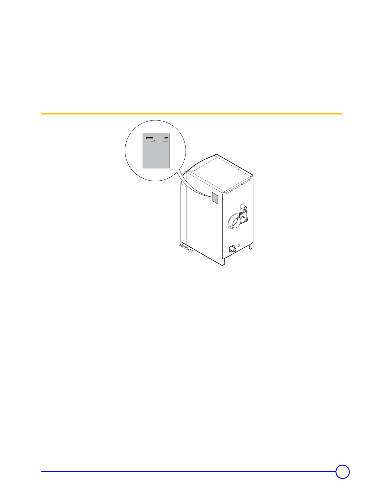
2.5 Rating plate
The rating plate identifies the product and provides information on:
- The date of manufacture: XX (Year) - XX (Week).
- The serial number.
(1) Except Belgium
*
1 mbar = 10 mmCE = 10 daPa = 100 Pa / 1 K =1 °C
(2) up to 60 kW
(3) up to 70 kW
(4) above 70 kW
** Specific flow: Minimum average rise in temperature of 30K that the appliance
can provide in the course of two successive draw-offs of 10 minutes
separated by a stop of 20 minutes.
(5) Heat exchanger inlet temperature: 80 °C
Domestic hot water temperature: 45 °C
(6) DHW setting = 60 °C - Average domestic hot water temperature:
40 °C - Boiler setting: 80 °C
*** Draw-off capacity: Hot water flow at which water can be drawn off during a
period of 10 minutes at a temperature of 30°C.
Outlet status: Water at 10°C in the boiler.
(7)
Cold water temperature: 10 °C
A
8
GT 220 - GT 2200 22/01/09 - 300008281-001-E
2. Description
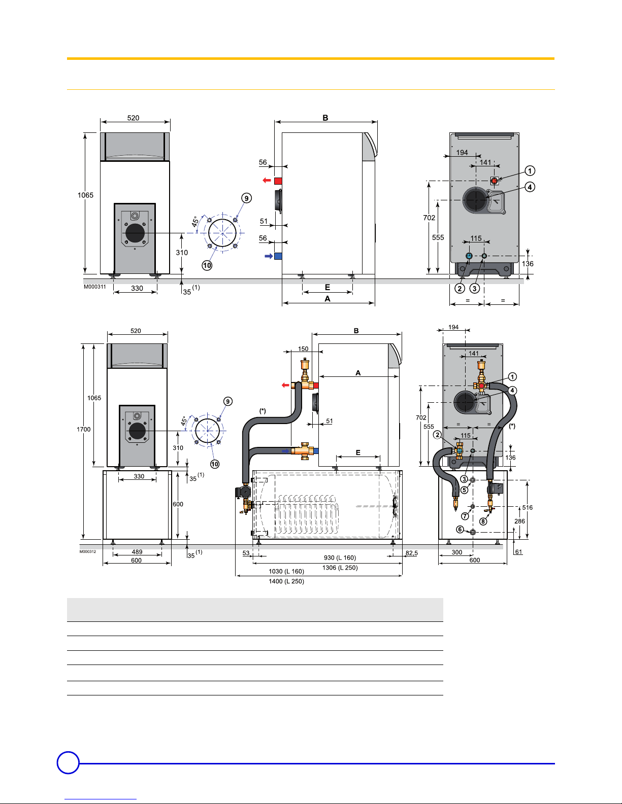
2.6 Main dimensions
2.6.1 Boiler and tank dimensions
• GT 220
• GT 2200
(*) Boiler and DHW calorifier connection kit
A
A
GT 224
GT 2204/160
GT 2204/250
GT 225
GT 2205/160
GT 2205/250
GT 226 GT 227 GT 228
A
700 700 827 827 954 1081 1208
B
772 772 899 899 1026 1153 1280
Ø C
153 153 153 153 180 180 180
R1 1/4 R1 1/2 R1 1/4 R1 1/2 R1 1/2 R1 1/2 R1 1/2
E
380 380 507 507 634 761 888
9
22/01/09 - 300008281-001-E GT 220 - GT 2200
2. Description
1. Heating outlet
2. Heating return
3. Drainage / filling orifice
Rp 3/4
4. Flue gas nozzle ø C
5. Domestic hot water outlet - G 1
6. Domestic cold water inlet - G 1
7. Domestic hot water circulation loop return - G 3/4
8. Filling and emptying tap
(connection for 14 mm interior diameter pipe)
9. 4xM8 on Ø 150 and 4 markings on Ø 170
10. Drilling Ø 110 - Precut Ø 130
R = Thread
Rp = Exterior cylindrical threading, sealed by flat joint
(1) Adjustable feet: Basic dimension 35 mm. Can be adjusted from
35 mm to 50 mm
(2) Adjustable feet: Basic dimension 35 mm. Can be adjusted from
35 mm to 40 mm
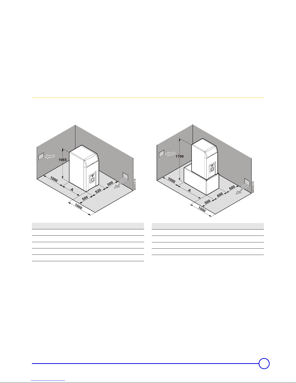
2.6.2 Installation dimensions
Keep space free around the boiler to ensure good accessibility to the appliance.
Minimum recommended dimensions (in mm):
• GT 220 • GT 2200
Boiler A (mm)
GT 224 700
GT 225 827
GT 226 954
GT 227 1081
GT 228 1208
Boiler A (mm)
GT 2204/160 930
GT 2204/250 1306
GT 2205/160 930
GT 2205/250 1306
 Loading...