

DeDietrich GT 220 A, GT 224A, GT 225A, GT 226A, GT 227A Operating Instructions Manual
...
GT 220 A
82274096
11-20-09
Oil-Gas Fired Hot Water boiler
English
11/20/09
Installation and operating instructions
Warning:
Before putting the boiler into operation read this manual
carefully.
Warning:
The operating manual is part of the documentation that is
or the gas supplier.
delivered to the installation’s operator. Go through the
information in this manual with the owner/operator and
make sure that he or she is familiar with all the necessary
operating instructions.
Notice:
This manual must be retained for future reference. Improper
installation, adjustment, alteration, service or maintenance can
cause injury, loss of life or property damage. For assistance or
additional information consult a qualified installer, service agency

Guideline of Notices
82274096
11-20-09
Safety Considerations
Warning:
indicates presence of hazards that can cause, if not
avoided, severe personal injury, death or substantial
property damage.
! Caution:
indicates presence of hazards t hat will or ca n cause, if not
avoided, minor personal injury or property damage.
Notice:
Application comment for optimum use of equipment and
adjustment as well as useful information.
Reference to an other instruction book.
Z
Observe the following symbols
DANGER
due to explosion of gas.
- Work only on gas components when you have a license to do so.
- Note t hat the a ssembly of gas and vent connections, the initial
start-up, the electrical connections, the mainte nance and service
can only be perfor med by a licensed se rvice contra ctor or
technician.
DANGER
due to electricity.
- Prior to doing any work on the heating system, disconnect all
electrical power to the boiler at the emergency switch.
- It is NOT sufficient to shut off only the boiler control!
! CAUTION!
SYSTEM DAMAGE
due to improper installation.
- Observe l ocal and state codes as well as common i ndustry
practices during the install ation and operation of the heating
appliance.
! CAUTION!
SYSTEM DAMAGE
due to inadequate cleaning and maintenance.
- A boiler cleaning and maintenance should be performed annually.
Verify complete system operation at the same time.
- Correct the prob lem immediately to prevent damage to the
system!
! Caution:
Refer to User’s Manual regar ding the carcinogenic hazard of
crystalline silica that may be found during installation, servicing
and removal of this boiler.
Please observe the following safety instructions.
Read this manual carefully.
Correct in stallation and adjustment of the burner and the control
panel is a precondition for safe, efficient operation of the boiler.
Read this manual and the specifications on the safety label carefully
before attempting to put the burner into operation.
Do not store or use gasoline or other flammable liquids in
the vicinity of this or any other appliance.
WHAT TO DO IF YOU SMELL GAS:
- Do not try to light any appliance.
- Do not touch any electric switch, do not use any phone in
your building.
- Immediately call your gas supplier from a neighbor’s
phone. Follow the gas supplier’s instructions.
- If you cannot reach your gas supplier, call the Fire
Department.
Installation and service must be performed by a qualified
installer, service agency or the gas supplier.
Warning:
Improper installation, adjustment, and/or operation could
cause carbon monoxide poisoning resulting in injury or
death.
This product must be installed and serviced by a
professional service technician who is experienced and
qualified in hot water boiler installation and gas
combustion.
! Caution: Strict compliance with these instructions is a
precondition for the correct operation of the boiler.
! IMPORTANT
Service on this boiler should be undertaken only by trained and
skilled personnel.
Keep bo iler area cle ar and free from combustible materials,
gasoline and other flammable vapors and liquids.
Do not place any obstruction in the boiler room that will hinder
the flow of combustion and ventilating air.
Read these instructions carefully before proceeding with the
installation of boiler. Post instructions near boiler for reference
by owner and serviceman.
Maintain instructions in legible condition.
"Installation of this equipment must be in accordance to all local and national codes or authorities having jurisdiction”
[Canadian Installations]
• CSA B149 for gas fired boilers
• CSA B139 for oil fired boilers
The boiler must be connected to a
venting system that will safely discharge
all flue gas to the outside in a safe and
effective manner.
2
• NFPA 54/ANSI Z223.1 for gas fired boiler
• NFPA 31 for oil fired boilers.
ATTENTION-WARNING:
Do not use gasoline, crankcase draining,
or any other oil containing gasoline.
GT 210 A 08/0121/08/06 - 94863106 - 82274096E
[USA Installations]
The boiler is certified to burn fuels as
listed on the boiler rating plate. Never
burn garbage or paper in the unit, and
never leave combustible materials in the
vicinity of the boiler.

Contents
82274096
11-20-09
Regulations and guidelines . . . . . . . . . . . . . . . . . . . . . . . . . . . . . . . . . . . . . . . . . . . . . . . . . . . . . . . . . . . . . . . . . . . .4
General . . . . . . . . . . . . . . . . . . . . . . . . . . . . . . . . . . . . . . . . . . . . . . . . . . . . . . . . . . . . . . . . . . . . . . . . . . . . . . . . . . . . .4
1 Uncrating . . . . . . . . . . . . . . . . . . . . . . . . . . . . . . . . . . . . . . . . . . . . . . . . . . . . . . . . . . . . . . . . . . . . . . . . . . . . . . . . . . . . . . . . . . . . . . . .4
2 Technical specifications of boilers . . . . . . . . . . . . . . . . . . . . . . . . . . . . . . . . . . . . . . . . . . . . . . . . . . . . . . . . . . . . . . . . . . . . . . . . . . . . .5
3 Main Dimensions . . . . . . . . . . . . . . . . . . . . . . . . . . . . . . . . . . . . . . . . . . . . . . . . . . . . . . . . . . . . . . . . . . . . . . . . . . . . . . . . . . . . . . . . . .6
Installation . . . . . . . . . . . . . . . . . . . . . . . . . . . . . . . . . . . . . . . . . . . . . . . . . . . . . . . . . . . . . . . . . . . . . . . . . . . . . . . . . .7
1 Location . . . . . . . . . . . . . . . . . . . . . . . . . . . . . . . . . . . . . . . . . . . . . . . . . . . . . . . . . . . . . . . . . . . . . . . . . . . . . . . . . . . . . . . . . . . . . . . . .7
2 Aeration . . . . . . . . . . . . . . . . . . . . . . . . . . . . . . . . . . . . . . . . . . . . . . . . . . . . . . . . . . . . . . . . . . . . . . . . . . . . . . . . . . . . . . . . . . . . . . . . .8
3 Levelling . . . . . . . . . . . . . . . . . . . . . . . . . . . . . . . . . . . . . . . . . . . . . . . . . . . . . . . . . . . . . . . . . . . . . . . . . . . . . . . . . . . . . . . . . . . . . . . . . 8
4 Water connection . . . . . . . . . . . . . . . . . . . . . . . . . . . . . . . . . . . . . . . . . . . . . . . . . . . . . . . . . . . . . . . . . . . . . . . . . . . . . . . . . . . . . . . . . .8
Assembly . . . . . . . . . . . . . . . . . . . . . . . . . . . . . . . . . . . . . . . . . . . . . . . . . . . . . . . . . . . . . . . . . . . . . . . . . . . . . . . . . . .9
Chimney connection . . . . . . . . . . . . . . . . . . . . . . . . . . . . . . . . . . . . . . . . . . . . . . . . . . . . . . . . . . . . . . . . . . . . . . . . .24
1 Flue size . . . . . . . . . . . . . . . . . . . . . . . . . . . . . . . . . . . . . . . . . . . . . . . . . . . . . . . . . . . . . . . . . . . . . . . . . . . . . . . . . . . . . . . . . . . . . . . .24
2 Connecting to the flue . . . . . . . . . . . . . . . . . . . . . . . . . . . . . . . . . . . . . . . . . . . . . . . . . . . . . . . . . . . . . . . . . . . . . . . . . . . . . . . . . . . . .24
Connecting the burner . . . . . . . . . . . . . . . . . . . . . . . . . . . . . . . . . . . . . . . . . . . . . . . . . . . . . . . . . . . . . . . . . . . . . . .24
Electrical connections. . . . . . . . . . . . . . . . . . . . . . . . . . . . . . . . . . . . . . . . . . . . . . . . . . . . . . . . . . . . . . . . . . . . . . . .25
Maintenance. . . . . . . . . . . . . . . . . . . . . . . . . . . . . . . . . . . . . . . . . . . . . . . . . . . . . . . . . . . . . . . . . . . . . . . . . . . . . . . .25
1 Boiler . . . . . . . . . . . . . . . . . . . . . . . . . . . . . . . . . . . . . . . . . . . . . . . . . . . . . . . . . . . . . . . . . . . . . . . . . . . . . . . . . . . . . . . . . . . . . . . . . .25
2 Domestic hot water (GT 2100) . . . . . . . . . . . . . . . . . . . . . . . . . . . . . . . . . . . . . . . . . . . . . . . . . . . . . . . . . . . . . . . . . . . . . . . . . . . . . . .26
3 Precautions required in the case of long boiler stops (one or more years) . . . . . . . . . . . . . . . . . . . . . . . . . . . . . . . . . . . . . . . . . . . . . 26
4 Precautions required if the heating is stopped when there is a risk of freezing . . . . . . . . . . . . . . . . . . . . . . . . . . . . . . . . . . . . . . . . . .26
5 Identification plate . . . . . . . . . . . . . . . . . . . . . . . . . . . . . . . . . . . . . . . . . . . . . . . . . . . . . . . . . . . . . . . . . . . . . . . . . . . . . . . . . . . . . . . .26
Spare parts - GT 210 A . . . . . . . . . . . . . . . . . . . . . . . . . . . . . . . . . . . . . . . . . . . . . . . . . . . . . . . . . . . . . . . . . . . . . . .27
01/08/08 - 82274096F GT 210 A
3
Regulations and guidelines
82274096
11-20-09
The installation must conform to the requirements of the authority
having jurisdiction or, in th e absence of such re quirements, to the
National Fuel Gas Code, ANSI Z 223.1 / NFPA 54. In Canada,
installation must be in accordance with the requirements of CAN/
CGA B149.1 or 2 Installation Code for Gas Burning Appliances and
Equipment. Where required by the authority having jurisdiction, the
installation must conform to the Standard for Controls and Safety
Devices for Automatically Fired Boilers, ANSI/ASME CSD-1.
Install CO detectors per lo cal r egulations. Boiler requires yearly
Only a qualified installing contractor may carry out the installation, the
initial st art-up, the connection for fixed gas and vent gas, and
conversion to another type of gas. The hot water distribution system
must comply with the applic able codes and regulations. When
replacing an existing boiler, it is important to check the entire hot
water distribution system to insure safe operation. Maintenance and
cleaning must be carried out at least once a year by a trained service
technician. The entire installation must be tested for proper
operation. Any defects detected must be fixed immediately.
maintenance, see "Connecting the burner", page 24.
General
The GT210A series is a cast iron sectional boiler designed for space and domestic and hot water heating requirements, the
boiler is automatically fired and controlled by the boiler control panel. The boiler is certified to burn all the fuels as listed on the rating
plate by separate burner. The boiler must always be connected to a vent system that will discharge all flue gases to
in a safe and effective manner. Refer to the specific sect
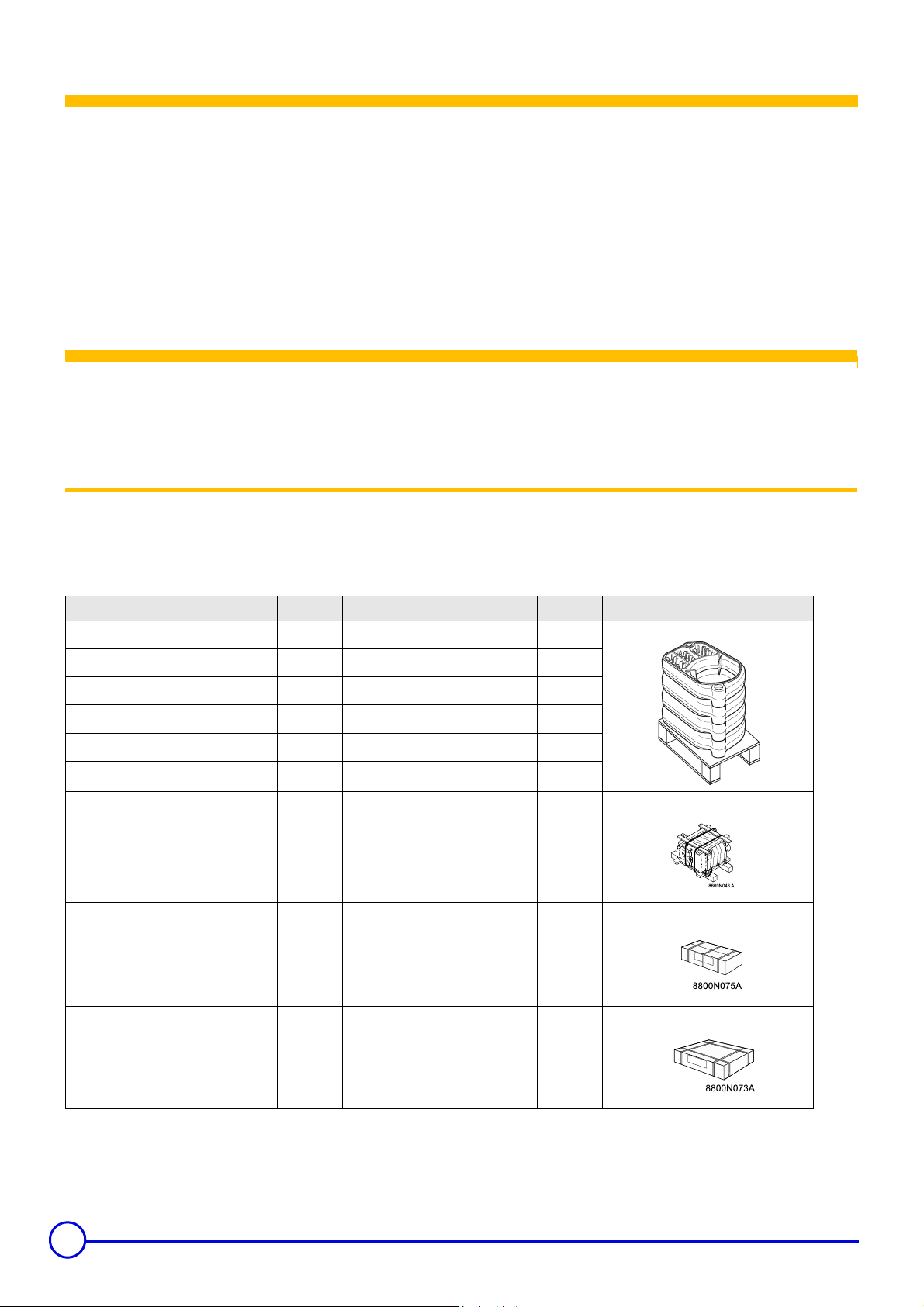
1 Uncrating
ions in the manual for further details.
Upon arrival, check shipment to ensure all parts have been shipped.
Inspect all items for delivery damage. Report all damage and shortages to the delivery carrier. Report any damage and shortages to
the Distributor.
Boiler GT 214 A GT 215 A GT 216 A GT 217 A GT 218 A
the outside
• Unassembled boiler body
- front section
- intermediate section
- rear section
- set of assembly rods
- accessory package
• Assembled boiler body
with accessories
Control panel
Casing
11111
23456
11111
- - 111
DR 64 DR 65 DR 66 DR 67 DR 68
DR 84 DR 85 DR 86 DR 87 DR 88
DR 90 DR 90 DR 90 DR 90 DR 90
DR 74
DR 75
DR 76
DR 77
DR 78
8800N072
4
GT 220A Series - Cast Iron Series
Item
Firing Sequence Consult Burner Technical Data
[CSA] - Gas Input
[CSA] - # 2 Fuel Oil Input
[CSA] - Output [Gas-Oil]
NET I=B=R Water Rating
Cast Iron Sections
Flue-way baffles
Water Capacity
Water
Resistance
[∆T = °F]
Combustion
Chamber
Dimensions
Combustion chamber
and flue way volume
ASME MAWP [Water]
Min. Safety Relief Capacity
Electrical Connection
Max. Water Temp.
Safety Limit [MR]
Water Operating
S2NA Panel
Temperature Range
Chamber Resistance
Gas-Vent Category
Boiler Vent Connection
Weight [Dry]
18° F
27° F
36° F
Diameter
[equivalent]
Depth
Volume
Volume
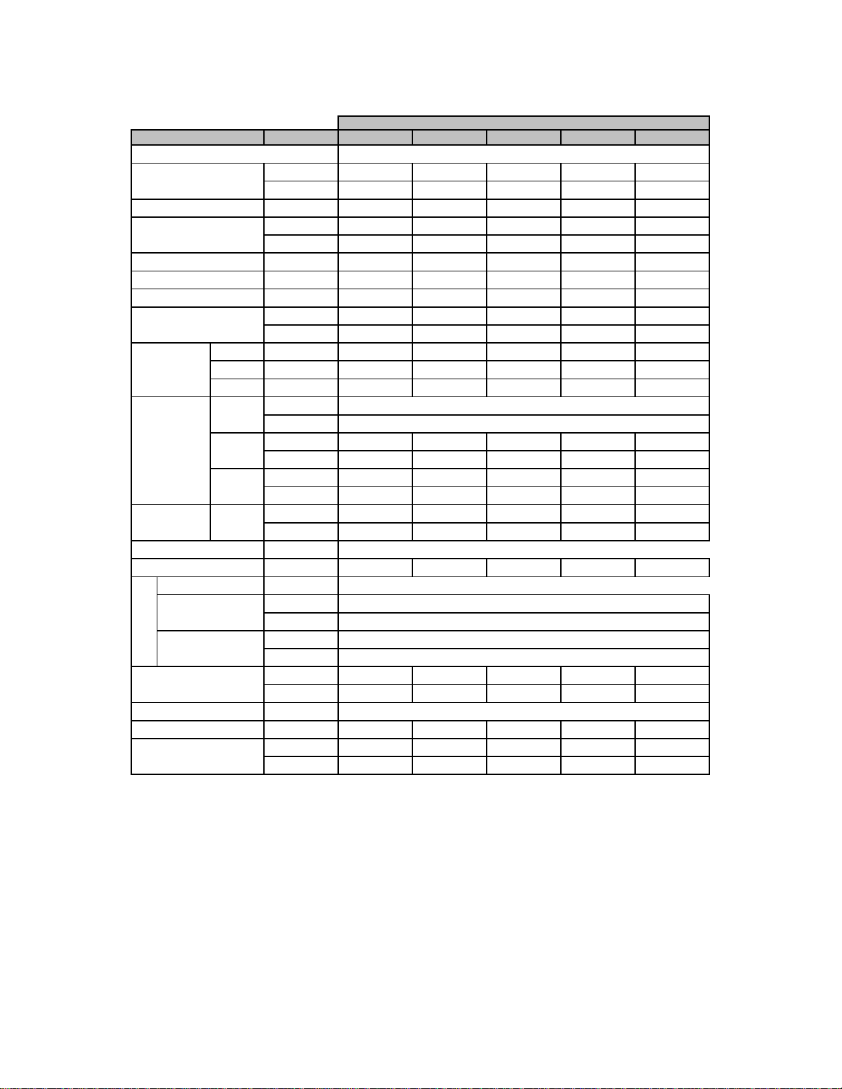
Technical Specification Data Table
Model
Unit GT 224A GT 225A GT 226A GT 227A GT 228A
US GPH
Ft. H
Ft. H
Ft. H
inch w.c.
MBH
kW
MBH
kW
MBH
#
#
US Gal
Liter
O [mbar]
2
O [mbar]
2
O [mbar]
2
Inch
mm
Inch
mm
3
Ft
3
m
3
3
Ft
3
m
PSI
MBH
V/P/H
° F
° C
° F
° C
mbar
#
inch
lb
kg
173 224 274 324 361
50.7 65.5 80.3 95.1 105.7
1.20 1.55 1.90 2.25 2.50
147 190 233 276 307
43.2 55.8 68.4 81.0 90.0
128 166 203 240 267
45678
32222
9.5 11.4 13.2 15.1 16.9
36 43 50 57 64
0.667 [19.952] 1.117 [33.391] 1.670 [49.904] 3.058 [91.409] 2.889 [86.368]
0.297 [8.867] 0.496 [14.840] 0.742 [22.180] 1.359 [40.613] 1.284 [38.375]
0.167 [4.988] 0.280 [8.355] 0.417 [12.467] 0.765 [22.852] 0.722 [21.592]
12.17
309
17.6 22.6 27.6 32.6 37.6
446 573 700 827 954
1.165 1.483 1.801 2.119 2.436
0.033 0.042 0.051 0.060 0.069
1.907 2.401 2.931 3.425 3.919
0.054 0.068 0.083 0.097 0.111
60
162 209 257 304 338
120/1/60 < 10A
230
110
86 - 194 (optional Hi-Temperature kit available)
30 - 90 (optional Hi-Temperature kit available)
0.08 0.12 0.12 0.16 0.24
0.20 0.30 0.30 0.40 0.60
I-II-III-IV & Sidewall
66777
481 567 655 741 827
218 257 297 336 375
Note:
• CSA - MBH Output based on Thermal Efficiency Test According to ANSI Z21.13a/CSA 4.9a-2005
• All Models Certified for 0 - 4,500 feet ASL installation altitude
• Chamber Resistance Based on Neutral Chimney-Vent Pressure
• Conversion Btu/Hr to kW = 3,412 Btu/Hr per kW
• All Models are Design Certified & Eligible to Bear Approval Marking as Shown.
• All Models Certified to Fire; # 2 oil, Natural & Propane Gases. Consult factory for Available Burners.
• All Models Comply and Certified in Accordance to the latest Canadian & US standards
•
Due to ongoing and continuous product improvements, DDR Americas Inc. reserves all rights to amend and delete information
provided on this product specification table.
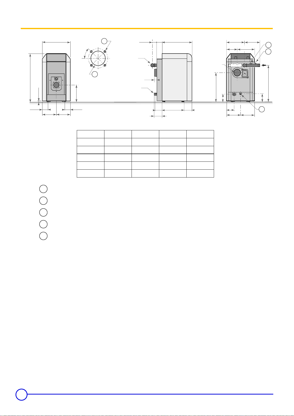
3 Main Dimensions (less applied burner)
13
7
9
/16
5
/8
3
4
22
1
/16
1
7
2
7
/8
/16
A4
B Ø
flue gas
nozzle
14
7
8
/16
heating
outlet
D Ø
/16
3
14
Model
GT 224A
GT 225A
GT 226A
GT 227A
2
A*
23 5/16 in.
28 5/16 in.
33 5/16 in.
38 5/16 in.
heating
return
D Ø
13
1
B = ø
6
6
7
7
/16
5
5
1
/8
9
/16
16 11/16 in.
21 11/16 in.
26 11/16 in.
31 11/16 in.
/16
/16
15
11
29
23
/16
7
7
3
C
6
/16
1
6
/2
==
C
D
/16
7
7
5
1¼ in.
1 ¼ in.
1 ½ in.
1 ½ in.
/8
7
38
2" (1)
1
/2
4
=
1
4
/2
=
GT 228A 43 5/16 in. 7 36 11/16 in. 1 ½ in.
Bolt Ø = 5 15/16 inch M8 x 1.25 Bolt diameter threading predrilled, additional
1
marking @ 6 ¾ inch for larger mounting requirements.
Combustion head Ø = 4 7/16 inch precut, additional marking @ 5 1/8 inch for larger
2
combustion heads.
Supply manifold ¾” port for safety relief valve
3
Supply manifold ¼ inch port for temperature and pressure gauge
4
Drain port ¾ inch.
5
A* = Dimension will increase with applied burner, consult supplied burner documentation for dimensions
and clearances for service/ combustibles.
D** = OD Dimension will for breeching connection only actual vent diameter sizing will depend on
specific vent application and code requirements.
(1) = Adjustable hot water tank feet for leveling, minimum height =1 3/16 inch, adjustable from 1 3/16 to 2 1/2 inch.
6
 Loading...