

DeDietrich GT 210 A, GT 214 A, GT 215 A, GT 216 A, GT 217 A Operating Manual
...
GT 210 A
Oil-Gas Fired Hot Water Boiler
English
11/03/09
Warning:
Before putting the boiler into operation read this manual
carefully.
Warning:
The operating manual is part of the documentation that is
delivered to the installation’s operator. Go through the
information in this manual with the owner/operator and
make sure that he or she is familiar with all the necessary
operating instructions.
Notice:
This manual must be retained for future reference. Improper
installation, adjustment, alteration, service or maintenance can
cause injury, loss of life or property damage. Refer to this
manual. For assistance or additional information consult a
qualified installer, service agency or the fuel supplier.
Installation & Operating Manual
Please Read & Save this Manual for Future Reference
8227-4096-F
8227-4096-F

2
GT 210 A 08/0121/08/06 - 94863106 - 82274096E
Guideline of Notices
Warning:
indicates presence of hazards that can cause, if not
avoided, severe personal injury, death or substantial
property damage.
! Caution:
indicates presence of hazards that will or can cause, if not
avoided, minor personal injury or property damage.
Notice:
Application comment for optimum use of equipment and
adjustment as well as useful information.
Z
Reference to an other instruction book.
Observe the following symbols
DANGER
due to explosion of gas.
- Work only on gas components when you have a license to do so.
- Note that the assembly of gas and vent connections, the initial
start-up, the electrical connections, the maintenance and service
can only be performed by a licensed service contractor or
technician.
DANGER
due to electricity.
- Prior to doing any work on the heating system, disconnect all
electrical power to the boiler at the emergency switch.
- It is NOT sufficient to shut off only the boiler control!
! CAUTION!
SYSTEM DAMAGE
due to improper installation.
- Observe local and state codes as well as common industry
practices during the installation and operation of the heating
appliance.
! CAUTION!
SYSTEM DAMAGE
due to inadequate cleaning and maintenance.
- A boiler cleaning and maintenance should be performed annually.
Verify complete system operation at the same time.
- Correct the problem immediately to prevent damage to the
system!
! Caution:
Refer to User’s Manual regarding the carcinogenic hazard of
crystalline silica that may be found during installation, servicing
and removal of this boiler.
Safety Considerations
Please observe the following safety instructions.
Read this manual carefully.
Correct installation and adjustment of the burner and the control
panel is a precondition for safe, efficient operation of the boiler.
Read this manual and the specifications on the safety label carefully
before attempting to put the burner into operation.
Do not store or use gasoline or other flammable liquids in
the vicinity of this or any other appliance.
WHAT TO DO IF YOU SMELL GAS:
- Do not try to light any appliance.
- Do not touch any electric switch, do not use any phone in
your building.
- Immediately call your gas supplier from a neighbor’s
phone. Follow the gas supplier’s instructions.
- If you cannot reach your gas supplier, call the Fire
Department.
Installation and service must be performed by a qualified
installer, service agency or the gas supplier.
Warning:
Improper installation, adjustment, and/or operation could
cause carbon monoxide poisoning resulting in injury or
death.
This product must be installed and serviced by a
professional service technician who is experienced and
qualified in hot water boiler installation and gas
combustion.
! Caution: Strict compliance with these instructions is a
precondition for the correct operation of the boiler.
! IMPORTANT
Service on this boiler should be undertaken only by trained and
skilled personnel.
Keep boiler area clear and free from combustible materials,
gasoline and other flammable vapors and liquids.
Do not place any obstruction in the boiler room that will hinder
the flow of combustion and ventilating air.
Read these instructions carefully before proceeding with the
installation of boiler. Post instructions near boiler for reference
by owner and serviceman.
Maintain instructions in legible condition.
"Installation of this equipment must be in accordance to all local and national codes or authorities having jurisdiction”
[Canadian Installations]
• CSA B149 for gas fired boilers
• CSA B139 for oil fired boilers
[USA Installations]
• NFPA 54/ANSI Z223.1 for gas fired boiler
• NFPA 31 for oil fired boilers.
ATTENTION-WARNING:
The boiler must be connected to a
venting system that will safely discharge
all flue gas to the outside in a safe and
effective manner.
Do not use gasoline, crankcase draining,
or any other oil containing gasoline.
The boiler is certified to burn fuels as
listed on the boiler rating plate. Never
burn garbage or paper in the unit, and
never leave combustible materials in the
vicinity of the boiler.

3
01/08/08 - 82274096F GT 210 A
Contents
Regulations and guidelines . . . . . . . . . . . . . . . . . . . . . . . . . . . . . . . . . . . . . . . . . . . . . . . . . . . . . . . . . . . . . . . . . . . .4
General . . . . . . . . . . . . . . . . . . . . . . . . . . . . . . . . . . . . . . . . . . . . . . . . . . . . . . . . . . . . . . . . . . . . . . . . . . . . . . . . . . . . .4
1 Uncrating . . . . . . . . . . . . . . . . . . . . . . . . . . . . . . . . . . . . . . . . . . . . . . . . . . . . . . . . . . . . . . . . . . . . . . . . . . . . . . . . . . . . . . . . . . . . . . . .4
2 Technical specifications of boilers . . . . . . . . . . . . . . . . . . . . . . . . . . . . . . . . . . . . . . . . . . . . . . . . . . . . . . . . . . . . . . . . . . . . . . . . . . . . .5
3 Main Dimensions . . . . . . . . . . . . . . . . . . . . . . . . . . . . . . . . . . . . . . . . . . . . . . . . . . . . . . . . . . . . . . . . . . . . . . . . . . . . . . . . . . . . . . . . . .6
Installation . . . . . . . . . . . . . . . . . . . . . . . . . . . . . . . . . . . . . . . . . . . . . . . . . . . . . . . . . . . . . . . . . . . . . . . . . . . . . . . . . .7
1 Location . . . . . . . . . . . . . . . . . . . . . . . . . . . . . . . . . . . . . . . . . . . . . . . . . . . . . . . . . . . . . . . . . . . . . . . . . . . . . . . . . . . . . . . . . . . . . . . . .7
2 Aeration . . . . . . . . . . . . . . . . . . . . . . . . . . . . . . . . . . . . . . . . . . . . . . . . . . . . . . . . . . . . . . . . . . . . . . . . . . . . . . . . . . . . . . . . . . . . . . . . .8
3 Levelling. . . . . . . . . . . . . . . . . . . . . . . . . . . . . . . . . . . . . . . . . . . . . . . . . . . . . . . . . . . . . . . . . . . . . . . . . . . . . . . . . . . . . . . . . . . . . . . . .8
4 Water connection . . . . . . . . . . . . . . . . . . . . . . . . . . . . . . . . . . . . . . . . . . . . . . . . . . . . . . . . . . . . . . . . . . . . . . . . . . . . . . . . . . . . . . . . . .8
Assembly . . . . . . . . . . . . . . . . . . . . . . . . . . . . . . . . . . . . . . . . . . . . . . . . . . . . . . . . . . . . . . . . . . . . . . . . . . . . . . . . . . .9
Chimney connection . . . . . . . . . . . . . . . . . . . . . . . . . . . . . . . . . . . . . . . . . . . . . . . . . . . . . . . . . . . . . . . . . . . . . . . . .24
1 Flue size. . . . . . . . . . . . . . . . . . . . . . . . . . . . . . . . . . . . . . . . . . . . . . . . . . . . . . . . . . . . . . . . . . . . . . . . . . . . . . . . . . . . . . . . . . . . . . . .24
2 Connecting to the flue . . . . . . . . . . . . . . . . . . . . . . . . . . . . . . . . . . . . . . . . . . . . . . . . . . . . . . . . . . . . . . . . . . . . . . . . . . . . . . . . . . . . .24
Connecting the burner . . . . . . . . . . . . . . . . . . . . . . . . . . . . . . . . . . . . . . . . . . . . . . . . . . . . . . . . . . . . . . . . . . . . . . .24
Electrical connections. . . . . . . . . . . . . . . . . . . . . . . . . . . . . . . . . . . . . . . . . . . . . . . . . . . . . . . . . . . . . . . . . . . . . . . .25
Maintenance. . . . . . . . . . . . . . . . . . . . . . . . . . . . . . . . . . . . . . . . . . . . . . . . . . . . . . . . . . . . . . . . . . . . . . . . . . . . . . . .25
1 Boiler . . . . . . . . . . . . . . . . . . . . . . . . . . . . . . . . . . . . . . . . . . . . . . . . . . . . . . . . . . . . . . . . . . . . . . . . . . . . . . . . . . . . . . . . . . . . . . . . . .25
2 Domestic hot water (GT 2100). . . . . . . . . . . . . . . . . . . . . . . . . . . . . . . . . . . . . . . . . . . . . . . . . . . . . . . . . . . . . . . . . . . . . . . . . . . . . . .26
3 Precautions required in the case of long boiler stops (one or more years) . . . . . . . . . . . . . . . . . . . . . . . . . . . . . . . . . . . . . . . . . . . . .26
4 Precautions required if the heating is stopped when there is a risk of freezing. . . . . . . . . . . . . . . . . . . . . . . . . . . . . . . . . . . . . . . . . .26
5 Identification plate . . . . . . . . . . . . . . . . . . . . . . . . . . . . . . . . . . . . . . . . . . . . . . . . . . . . . . . . . . . . . . . . . . . . . . . . . . . . . . . . . . . . . . . .26
Spare parts - GT 210 A . . . . . . . . . . . . . . . . . . . . . . . . . . . . . . . . . . . . . . . . . . . . . . . . . . . . . . . . . . . . . . . . . . . . . . .27
4
GT 210 A 21/08/06 - 94863106 - 82274096E
Regulations and guidelines
The installation must conform to the requirements of the authority
having jurisdiction or, in the absence of such requirements, to the
National Fuel Gas Code, ANSI Z 223.1 / NFPA 54. In Canada,
installation must be in accordance with the requirements of CAN/
CGA B149.1 or 2 Installation Code for Gas Burning Appliances and
Equipment. Where required by the authority having jurisdiction, the
installation must conform to the Standard for Controls and Safety
Devices for Automatically Fired Boilers, ANSI/ASME CSD-1.
Install CO detectors per local regulations. Boiler requires yearly
maintenance, see "Connecting the burner", page 24.
Only a qualified installing contractor may carry out the installation, the
initial start-up, the connection for fixed gas and vent gas, and
conversion to another type of gas. The hot water distribution system
must comply with the applicable codes and regulations. When
replacing an existing boiler, it is important to check the entire hot
water distribution system to insure safe operation. Maintenance and
cleaning must be carried out at least once a year by a trained service
technician. The entire installation must be tested for proper
operation. Any defects detected must be fixed immediately.
General
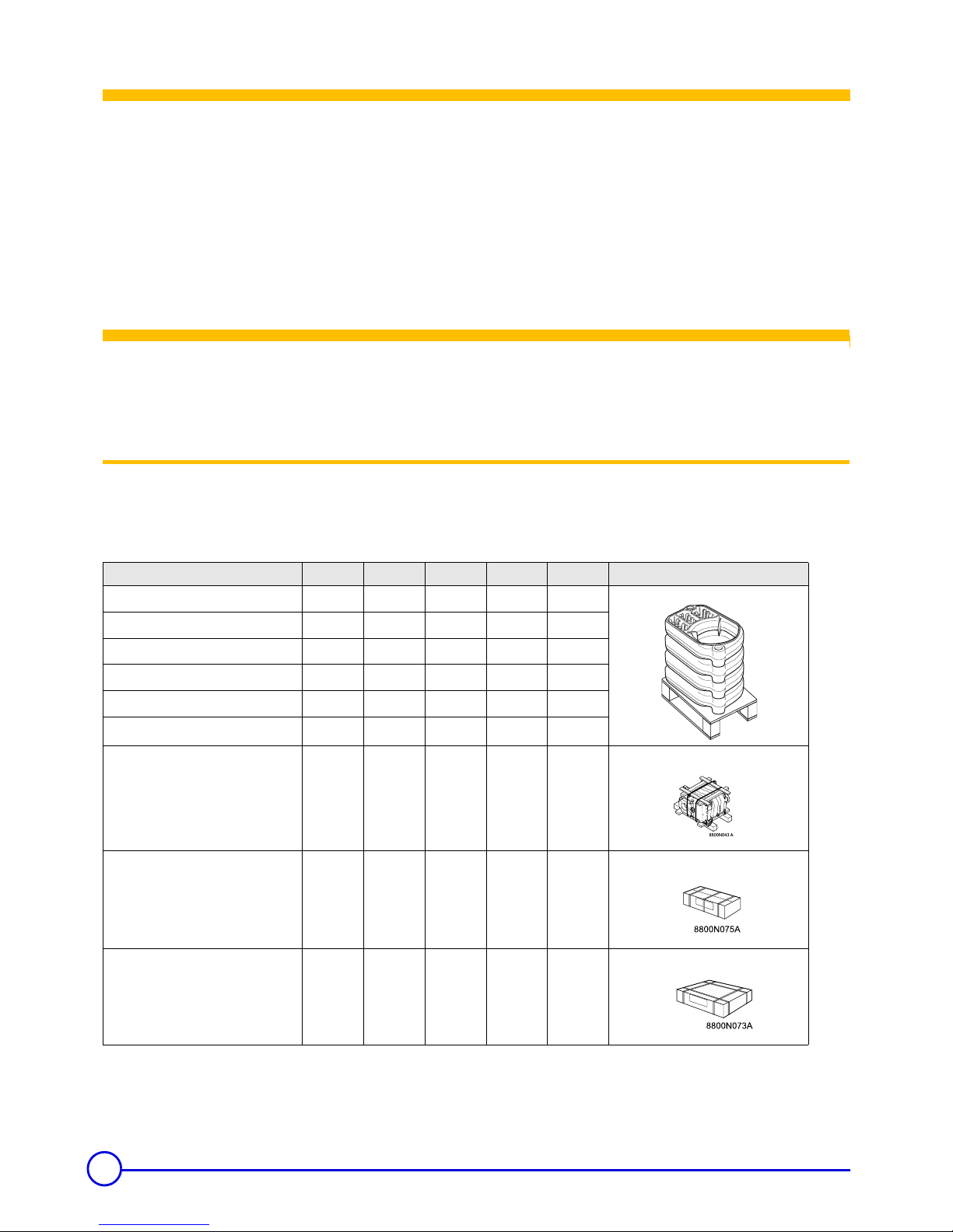
1 Uncrating
Upon arrival, check shipment to ensure all parts have been shipped.
Inspect all items for delivery damage. Report all damage and shortages to the delivery carrier. Report any damage and shortages to
the Distributor.
Boiler GT 214 A GT 215 A GT 216 A GT 217 A GT 218 A
• Unassembled boiler body
- front section
11111
- intermediate section
23456
- rear section
11111
- set of assembly rods
--111
- accessory package
DR 64 DR 65 DR 66 DR 67 DR 68
• Assembled boiler body
with accessories
DR 84 DR 85 DR 86 DR 87 DR 88
Control panel
DR 90 DR 90 DR 90 DR 90 DR 90
Casing
DR 74
DR 75
DR 76
DR 77
DR 78
8800N072
The GT210A series is a cast iron sectional boiler designed for space and domestic and hot water heating requirements, the
boiler is automatically fired and control
led by the boiler control panel. The boiler is certified to burn all the fuels as listed on the rating
plate by separat
e burner. The boiler must always be connected to a vent system that will discharge all flue gases to the outside
in a safe and effective manner. Refer to the specific sections in the manual for further details.
5
21/08/06 - 94863106 - 82274096E GT 210 A
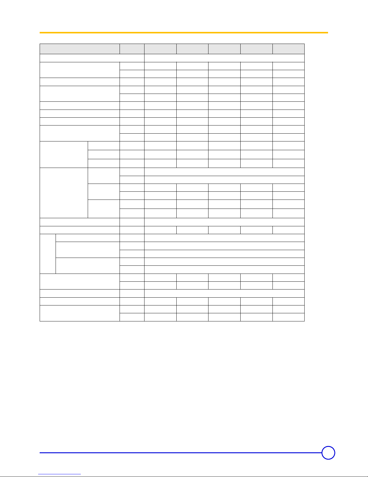
2 Technical specifications of boilers
Item Unit GT 214 A GT 215 A GT 216 A GT 217 A GT 218 A
Firing Sequence Consult Burner Technical Data
[CSA] - Gas Input
MBH 173 224 274 324 361
kW 50.7 65.7 80.3 95.0 105.8
[CSA] - # 2 Fuel Oil Input US GPH 1.20 1.55 1.90 2.25 2.50
[CSA] - Output [Gas-Oil]
MBH 147 190 233 276 306
kW 43.1 55.7 68.3 80.8 89.8
[NET] - Output [Gas-Oil] MBH 128 165 203 240 266
Cast Iron sections #45678
Flue-way baffles #32222
Water capacity
US Gal 9.5 11.4 13.2 15.1 16.9
Liter3643505764
Water resistance
[
∆t = °F]
18° F
Ft. H
2
O
0.82 1.34 1.99 2.77 3.4
27° F
Ft. H
2
O
0.365 0.596 0.887 1.23 1.51
36° F
Ft. H
2
O
0.204 0.335 0.498 0.693 0.85
Combustion chamber
Dimensions
Diameter
[equivalent]
Inch 12.17
mm 309
Depth
Inch 17.6 22.6 27.6 32.6 37.6
mm 446 573 700 827 954
Volume
ft
3
1.1653 1.4831 1.8009 2.1188 2.4366
m
3
0.033 0.042 0.051 0.060 0.069
MAWP [Water] PSI ASME IV Rating Class 30 - (60 PSI) [See Canadian Provincial CRN approvals]
Min. Safety Relief Capacity MBH 147 190 233 276 306
DR 90 Panel
Electrical connection V/P/H 120/1/60
Max. Water Temp. Safety Limit
[MR]
°F 230
°C 110
Operating Water Temperature
Range
°F 86 - 185
°C 30 - 85
Chamber resistance
Inch w.c. 0.08 - 0.16 0.20 - 0.24 0.08 - 0.24 0.16 - 0.24 0.24 - 0.32
mbar
0.2 - 0.4 0.5 - 0.6 0.2 - 0.6 0.4 - 0.6 0.6 - 0.8
Gas-Vent Category # I, II - III or IV
Boiler Vent connectionInch66777
Weight (dry)
lb 481 567 655 741 827
kg 218 257 297 336 375
6
GT 210 A 01/08/08 - 82274096F
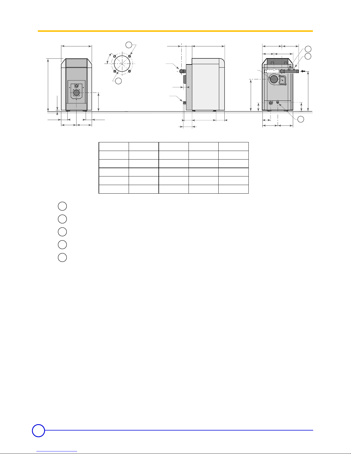
3 Main Dimensions (less applied burner)
22
1
/16
38
7
/8
2" (1)
7
7
/16
29
11
/16
7
7
/16
23
15
/16
8
7
/16
A4
7
/16
2
7
/8
13
5
/8
9
7
/16
14
=
=
heating
outlet
D Ø
heating
return
D Ø
4
1
/2
4
1
/2
5
1
/8
1
13
/16
6
3
/16
5
9
/16
C
6
1
/2
==
B Ø
flue gas
nozzle
14
3
/16
1
2
3
4
5
Model
GT 214A
GT 215A
GT 216A
GT 217A
A*
23 5/16 in.
28 5/16 in.
33 5/16 in.
38 5/16 in.
B = ø
6
6
7
7
C
16 11/16 in.
21 11/16 in.
26 11/16 in.
31 11/16 in.
D
1¼ in.
1 ¼ in.
1 ½ in.
1 ½ in.
GT 218A 43 5/16 in. 7 36 11/16 in. 1 ½ in.
2
3
Bolt Ø = 5 15/16 inch M8 x 1.25 Bolt diameter threading predrilled, additional
marking @ 6 ¾ inch for larger mounting requirements.
4
5
Combustion head Ø = 4 7/16 inch precut, additional marking @ 5 1/8 inch for larger
combustion heads.
Supply manifold ¾” port for safety relief valve
Supply manifold ¼ inch port for temperature and pressure gauge
Drain port ¾ inch.
1
A* = Dimension will increase with applied burner, consult supplied burner documentation for dimensions
and clearances for service/ combustibles.
D** = OD Dimension will for breeching connection only actual vent diameter sizing will depend on
specific vent application and code requirements.
(1) = Adjustable hot water tank feet for leveling, minimum height =1 3/16 inch, adjustable from 1 3/16 to 2 1/2 inch.
7
01/08/08 - 82274096F GT 210 A
L
X
8227N058A
3/4"-1"
To facilitate boiler transportation into the final installation site, a
special handling tool (package BG 45, no.8218-7723) may be used
as shown to transport the boiler or the boiler on the MLS horizontal
domestic hot water tank. The two 3/4” or 1” pipes are shown are not
supplied with the package BG45, they are supplied by others.
Installation
1 Installing the boiler
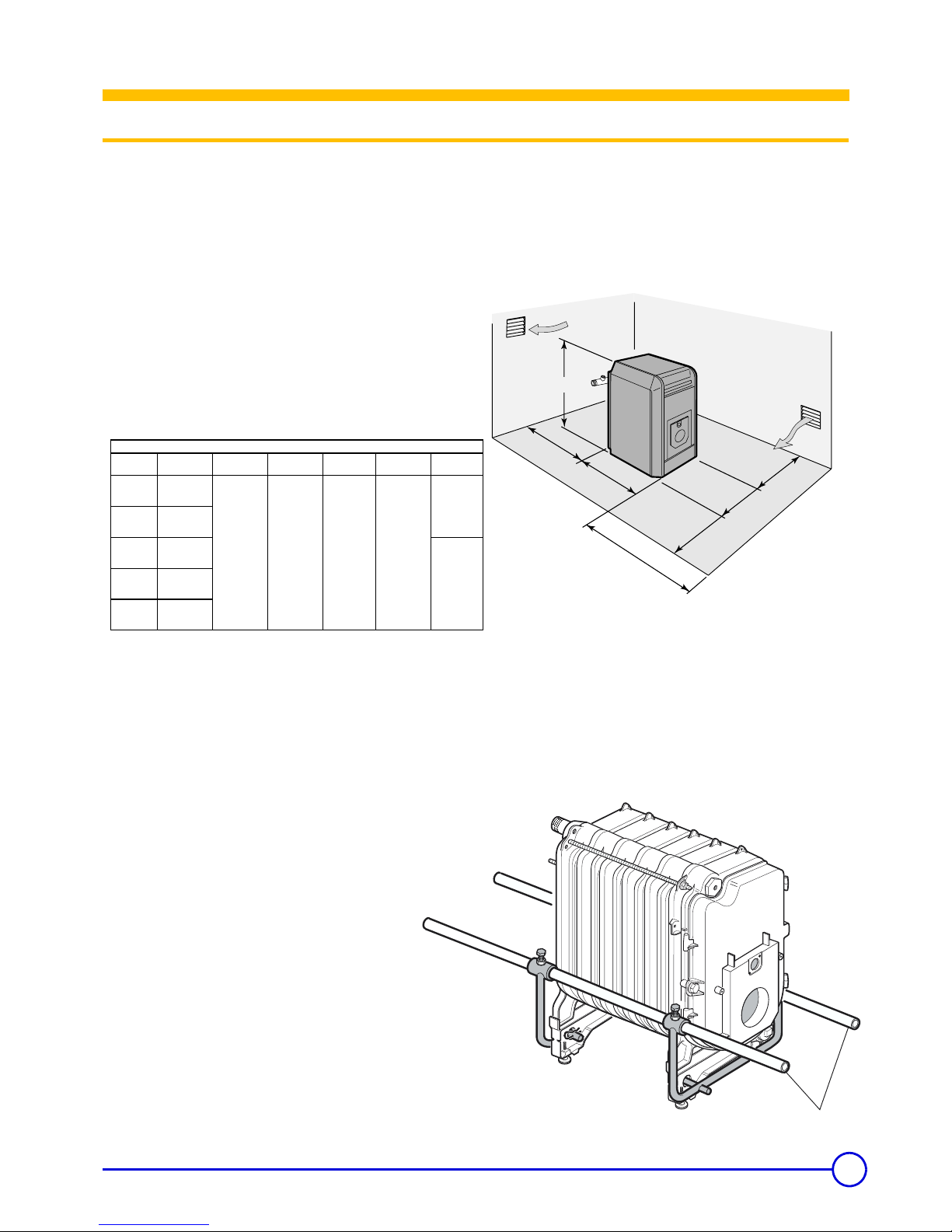
The boiler does not require any special housekeeping pad as it has been provided with a study frame and leveling bolts for the
final installation, but a non combustible pad is suggested to keep occasional water away from the boiler. The boiler requires
clearance for combustibles and for servicing, the recommended clearance as shown in the table below. Do not install the boiler
on combustible flooring or carpet.
Proper combustion air and ventilation are required for the boiler, inadequate combustion air or makeup air provisions may result
in foul boiler room odors, incomplete combustion resulting in carbon monoxide (CO) development or creation of negative building
pressure.
Particular attention must be observed if the boiler is operating near or within vicinity of beauty shops, paint shops or
industrial plant where known pollutants, corrosive element may containment affect the quality of combustion air supply, failure to
observe this warnings will result in void of warranty of the boiler and any responsibility of De Dietrich.
Consult local codes for combustion air and ventilation requirements, each installation must comply with all local and national
codes having jurisdiction.
Model
L = overall
len
g
th
Sides Rear
X = Front
burner
Top Vent
GT214A
29
11/16
[754mm]
GT215A
34
11/16
[881mm]
GT216A
39
11/16
[1008mm]
GT217A
32
11/16
[1135mm]
GT218
33
11/16
[1262mm]
20 inches
[500mm]
20 inches
[500mm]
34 inches
[800mm]
24 inches
[600mm] in
front of burner
Combustible & Service Clearances
GAS =
6 inches
[150mm]
OIL =
9 inches
[230mm]
 Loading...