

DeDietrich GT 123 A, GT 125 A, GT 124 A, GT 126 A Installation And Maintenance Manual
GT 120 A - GT 1200 A
Please Read & Save This Manual for Future Reference
Oil-Gas Fired Hot Water Boiler
English
09/02/08
GT 120 A
GT 1200 A
Assembly, installation and maintenance manual
Warning:
Before putting the boiler into operation read this manual
carefully.
Warning:
The operating manual is part of the documentation that is
delivered to the installation’s operator. Go through the
information in this manual with the owner/operator and
make sure that he or she is familiar with all the necessary
operating instructions.
Notice:
This manual must be retained for future reference. Improper
installation, adjustment, alteration, service or maintenance can
cause injury, loss of life or property damage. Refer to this
manual. For assistance or additional information consult a
qualified installer, service agency or the gas supplier.
94863361

Guideline of Notices
Do not use gasoline, crankcase draining, or any other oil
containing gasoline.
Never Burn garbage or paper in the unit, and never leave
combustible material around it.
Safety Considerations
Warning:
indicates presence of hazards that can cause, if not
avoided, severe personal injury, death or substantial
property damage.
! Caution:
indicates presence of hazards that will or can cause, if not
avoided, minor personal injury or property damage.
Notice:
Application comment for optimum use of equipment and
adjustment as well as useful information.
Reference to an other instruction book.
Z
Observe the following symbols
DANGER
due to explosion of gas.
- Work only on gas components when you have a license to do so.
- Note that the assembly of gas and vent connections, the initial
start-up, the electrical connections, the maintenance and service
can only be performed by a licensed service contractor or
technician.
DANGER
due to electricity.
- Prior to doing any work on the heating system, disconnect all
electrical power to the boiler at the emergency switch.
- It is NOT sufficient to shut off only the boiler control!
! CAUTION!
SYSTEM DAMAGE
due to improper installation.
- Observe local and state codes as well as common industry
practices during the installation and operation of the heating
appliance.
! CAUTION!
SYSTEM DAMAGE
due to inadequate cleaning and maintenance.
- A boiler cleaning and maintenance should be performed annually.
Verify complete system operation at the same time.
- Correct the problem immediately to prevent damage to the
system!
! Caution:
Refer to User’s Manual regarding the carcinogenic hazard of
crystalline silica that may be found during installation, servicing
and removal of this boiler.
Please observe the following safety instructions.
Read this manual carefully.
Correct installation and adjustment of the burner and the control
panel is a precondition for safe, efficient operation of the boiler.
Read this manual and the specifications on the safety label carefully
before attempting to put the burner into operation.
Do not store or use gasoline or other flammable liquids in
the vicinity of this or any other appliance.
WHAT TO DO IF YOU SMELL GAS:
- Do not try to light any appliance.
- Do not touch any electric switch, do not use any phone in
your building.
- Immediately call your gas supplier from a neighbor’s
phone. Follow the gas supplier’s instructions.
- If you cannot reach your gas supplier, call the Fire
Department.
Installation and service must be performed by a qualified
installer, service agency or the gas supplier.
Warning:
Improper installation, adjustment, and/or operation could
cause carbon monoxide poisoning resulting in injury or
death.
This product must be installed and serviced by a
professional service technician who is experienced and
qualified in hot water boiler installation and gas
combustion.
! Caution: Strict compliance with these instructions is a
precondition for the correct operation of the boiler.
! IMPORTANT
Service on this boiler should be undertaken only by trained and
skilled personnel.
Keep boiler area clear and free from combustible materials,
gasoline and other flammable vapors and liquids.
Do not place any obstruction in the boiler room that will hinder
the flow of combustion and ventilating air.
Read these instructions carefully before proceeding with the
installation of boiler. Post instructions near boiler for reference
by owner and serviceman.
Maintain instructions in legible condition.
“Installation of this equipment must be in accordance to all local
codes and authorities having jurisdication, in conjunction with
national codes”
- Canadian Installations: CSA B149.1 & .2 for gas fired boilers &
CSA B139 for oil fired boilers
- USA Installations: NFPA 31 for oil fired boilers & NFPA 54/ANSI
Z223.1 for gas fired boilers
2
“Please consult all applicable codes having jurisdication in
which the boiler is being installed”
The boiler must be connected to a venting system that will
safely discharge all flue gases outside effectively and safely.
GT 120 A - GT 1200 A 09/02/08 - 94863361 - 85784009D

Contents
Contents . . . . . . . . . . . . . . . . . . . . . . . . . . . . . . . . . . . . . . . . . . . . . . . . . . . . . . . . . . . . . . . . . . . . . . . . . . . . . . . . . . . .3
Regulations and guidelines . . . . . . . . . . . . . . . . . . . . . . . . . . . . . . . . . . . . . . . . . . . . . . . . . . . . . . . . . . . . . . . . . . . .4
General . . . . . . . . . . . . . . . . . . . . . . . . . . . . . . . . . . . . . . . . . . . . . . . . . . . . . . . . . . . . . . . . . . . . . . . . . . . . . . . . . . . . .4
1 Uncrating . . . . . . . . . . . . . . . . . . . . . . . . . . . . . . . . . . . . . . . . . . . . . . . . . . . . . . . . . . . . . . . . . . . . . . . . . . . . . . . . . . . . . . . . . . . . . . . .4
2 Technical specifications of boilers . . . . . . . . . . . . . . . . . . . . . . . . . . . . . . . . . . . . . . . . . . . . . . . . . . . . . . . . . . . . . . . . . . . . . . . . . . . . .5
3 Main Dimensions . . . . . . . . . . . . . . . . . . . . . . . . . . . . . . . . . . . . . . . . . . . . . . . . . . . . . . . . . . . . . . . . . . . . . . . . . . . . . . . . . . . . . . . . . .6
Installation . . . . . . . . . . . . . . . . . . . . . . . . . . . . . . . . . . . . . . . . . . . . . . . . . . . . . . . . . . . . . . . . . . . . . . . . . . . . . . . . . .8
1 Location . . . . . . . . . . . . . . . . . . . . . . . . . . . . . . . . . . . . . . . . . . . . . . . . . . . . . . . . . . . . . . . . . . . . . . . . . . . . . . . . . . . . . . . . . . . . . . . . .8
2 Combustion air requirements. . . . . . . . . . . . . . . . . . . . . . . . . . . . . . . . . . . . . . . . . . . . . . . . . . . . . . . . . . . . . . . . . . . . . . . . . . . . . . . . .8
Assembly . . . . . . . . . . . . . . . . . . . . . . . . . . . . . . . . . . . . . . . . . . . . . . . . . . . . . . . . . . . . . . . . . . . . . . . . . . . . . . . . . . .9
Piping connections . . . . . . . . . . . . . . . . . . . . . . . . . . . . . . . . . . . . . . . . . . . . . . . . . . . . . . . . . . . . . . . . . . . . . . . . . .19
1 Dimensional Information. . . . . . . . . . . . . . . . . . . . . . . . . . . . . . . . . . . . . . . . . . . . . . . . . . . . . . . . . . . . . . . . . . . . . . . . . . . . . . . . . . . .19
2 Example of installation. . . . . . . . . . . . . . . . . . . . . . . . . . . . . . . . . . . . . . . . . . . . . . . . . . . . . . . . . . . . . . . . . . . . . . . . . . . . . . . . . . . . .20
Chimney connection - Venting . . . . . . . . . . . . . . . . . . . . . . . . . . . . . . . . . . . . . . . . . . . . . . . . . . . . . . . . . . . . . . . . .21
1 Flue size. . . . . . . . . . . . . . . . . . . . . . . . . . . . . . . . . . . . . . . . . . . . . . . . . . . . . . . . . . . . . . . . . . . . . . . . . . . . . . . . . . . . . . . . . . . . . . . .21
2 Dimensional information required for the connection. . . . . . . . . . . . . . . . . . . . . . . . . . . . . . . . . . . . . . . . . . . . . . . . . . . . . . . . . . . . . .21
3 Venting layout. . . . . . . . . . . . . . . . . . . . . . . . . . . . . . . . . . . . . . . . . . . . . . . . . . . . . . . . . . . . . . . . . . . . . . . . . . . . . . . . . . . . . . . . . . . .21
4 Termination location. . . . . . . . . . . . . . . . . . . . . . . . . . . . . . . . . . . . . . . . . . . . . . . . . . . . . . . . . . . . . . . . . . . . . . . . . . . . . . . . . . . . . . .26
Connecting the burner . . . . . . . . . . . . . . . . . . . . . . . . . . . . . . . . . . . . . . . . . . . . . . . . . . . . . . . . . . . . . . . . . . . . . . .28
Electrical connections. . . . . . . . . . . . . . . . . . . . . . . . . . . . . . . . . . . . . . . . . . . . . . . . . . . . . . . . . . . . . . . . . . . . . . . .28
Start up . . . . . . . . . . . . . . . . . . . . . . . . . . . . . . . . . . . . . . . . . . . . . . . . . . . . . . . . . . . . . . . . . . . . . . . . . . . . . . . . . . . .28
Periodic maintenance and checks . . . . . . . . . . . . . . . . . . . . . . . . . . . . . . . . . . . . . . . . . . . . . . . . . . . . . . . . . . . . . .29
1 Installation . . . . . . . . . . . . . . . . . . . . . . . . . . . . . . . . . . . . . . . . . . . . . . . . . . . . . . . . . . . . . . . . . . . . . . . . . . . . . . . . . . . . . . . . . . . . . .29
2 Boiler . . . . . . . . . . . . . . . . . . . . . . . . . . . . . . . . . . . . . . . . . . . . . . . . . . . . . . . . . . . . . . . . . . . . . . . . . . . . . . . . . . . . . . . . . . . . . . . . . .29
1 Precautions required in the case of long boiler stops (one or more years) . . . . . . . . . . . . . . . . . . . . . . . . . . . . . . . . . . . . . . . . . . . . .31
2 Precautions required if the heating is stopped when there is a risk of freezing. . . . . . . . . . . . . . . . . . . . . . . . . . . . . . . . . . . . . . . . . .31
Spare parts - GT 120 A - GT 1200 A . . . . . . . . . . . . . . . . . . . . . . . . . . . . . . . . . . . . . . . . . . . . . . . . . . . . . . . . . . . . .32
09/02/08 - 94863361 - 85784009D GT 120 A - GT 1200 A
3

Regulations and guidelines
The installation must conform to the requirements of the authority
having jurisdiction or, in the absence of such requirements, to the
National Fuel Gas Code, ANSI Z 223.1 / NFPA 54. In Canada,
installation must be in accordance with the requirements of CAN/
CGA B149.1 or 2 Installation Code for Gas Burning Appliances and
Equipment. Where required by the authority having jurisdiction, the
installation must conform to the Standard for Controls and Safety
Devices for Automatically Fired Boilers, ANSI/ASME CSD-1.
Install CO detectors per local regulations. Boiler requires yearly
maintenance, see "Connecting the burner", page 28.
The boilers of the GT 120 A range are automatic independent hotwater boilers designed for connecting to a flue which require a sepa-
1 Uncrating
Upon arrival, check shipment to ensure all parts have been shipped.
Inspect all items for delivery damage. Report all damage and shortages to the delivery carrier. Report any damage and shortages to
the Distributor.
Only a qualified installing contractor may carry out the installation, the
initial start-up, the connection for fixed gas and vent gas, and
conversion to another type of gas. The hot water distribution system
must comply with the applicable codes and regulations. When
replacing an existing boiler, it is important to check the entire hot
water distribution system to insure safe operation. Maintenance and
cleaning must be carried out at least once a year by a trained service
technician. The entire installation must be tested for proper
operation. Any defects detected must be fixed immediately.
General
rate fuel oil or gas burner.
Parts list:
Boiler Box nr. GT 123 A GT 124 A GT 125 A GT 126 A
Assembled boiler body
Control S2NA panel
or
E (Easymatic)
MA3 1
MA4 1
MA5 1
MA6 1
ME50
or
FM199
ME50
or
FM199
ME50
or
FM199
ME50
FM199
or
4
GT 120 A - GT 1200 A 09/02/08 - 94863361 - 85784009D
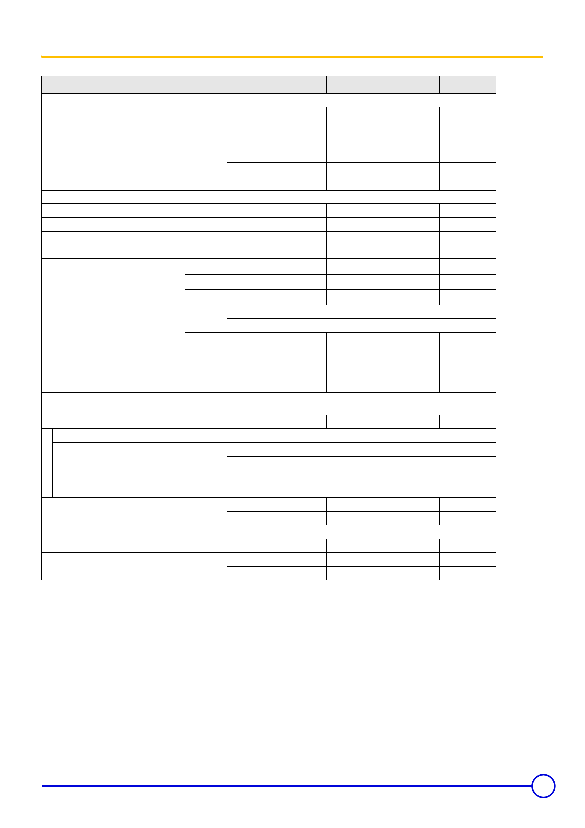
2 Technical specifications of boilers
Item Unit GT 123 A GT 124 A GT 125 A GT 126 A
Firing Sequence Gas-Oil - On-Off - Single Stage Only
[CSA] - Gas Input
[CSA] - # 2 Fuel Oil Input US GPH 0.65 0.80 1.00 1.15
[CSA] - Output [Gas-Oil]
[NET] - Output [Gas-Oil] MBH 68 83 104 120
[CSA] - AFUE Effy. % Gas 85% & Oil 87%
Cast Iron Sections # 3 4 5 6
+HDWLQJVXUIDFHDUHD6TIW
Water capacity
Water resistance
[
∆t = °F]
Combustion chamber
Dimensions
MAWP [Water] PSI
Min. Safety Relief Capacity MBH
Electrical Connection V/P/H 120/1/60
Maximum Temperature [Water]
S2NA Panel
Operating Water Temperature Range
Chamber Resistance
Gas-Vent Category # I, II - III or IV
Boiler Vent Connection Inch 5 5 5 6
Weight [Dry]
18° F
27° F
36° F
Diameter
[Equivalent]
Depth
Volume
MBH 94 115 144 166
kW 27.5 33.7 42.2 48.65
MBH 78 96 120 138
kW 22.9 28.1 35.2 40.4
US Gal 5 6.5 7.9 9.4
Liter 19 24.5 30 35.5
O
Ft. H
2
Ft. H2O
Ft. H2O
Inch 9.45
mm 240
Inch 12.13 17.13 22.13 27.13
mm 308 435 562 689
3
ft
3
m
°F 230
°C 110
°F 104 - 212
°C 40 - 100
Inch w.c. 0.06 0.09 0.09 0.09
mbar
lb 302 357 412 470
kg 137 162 187 213
0.13 0.20 0.30 0.42
0.06 0.09 0.14 0.19
0.03 0.05 0.08 0.11
0.57 0.74 0.92 1.09
16.0 21.0 26.0 31.0
ASME IV Rating Class 30 - (60 PSI) [See Canadian Provincial CRN
78
0.15 0.22 0.22 0.22
approvals]
96 120 138
M
- CSA - MBH Output based on Thermal Efficiency Test According to
ANSI Z21.13a/CSA 4.9a-2005
- [NET] MBH Output Factor 1.15, Allowance for Piping and Pickup
Losses
- All Models Comply and Certified in Accordance to the latest
Canadian & US standards
- To Obtain Current IBR Ratings, consult their publications and
website.
- Chamber Resistance Based on Neutral Chimney-Vent Pressure
- Gas Vent Category Based on Several Factors [CO2 content, Vent
Pressure & Net-Flue Gas Temp]
- Approved for Direct-Vent, Use Only Approved Venting as Listed
- Natural Draft Applications, Approved for Type L vent [Gas-Oil] or
Type B Vent [Gas Only]
- Conversion Btu to kW = 3,412 Btu per kW
- All Models are Design Certified & Eligible to Bear Approval Marking
as Shown.
- All Models Certified to Fire; # 2 oil, Natural & Propane Gases.
Consult factory for Available Burners.
02/10/06 - 94863361 - 85784009D GT 120 A - GT 1200 A
5
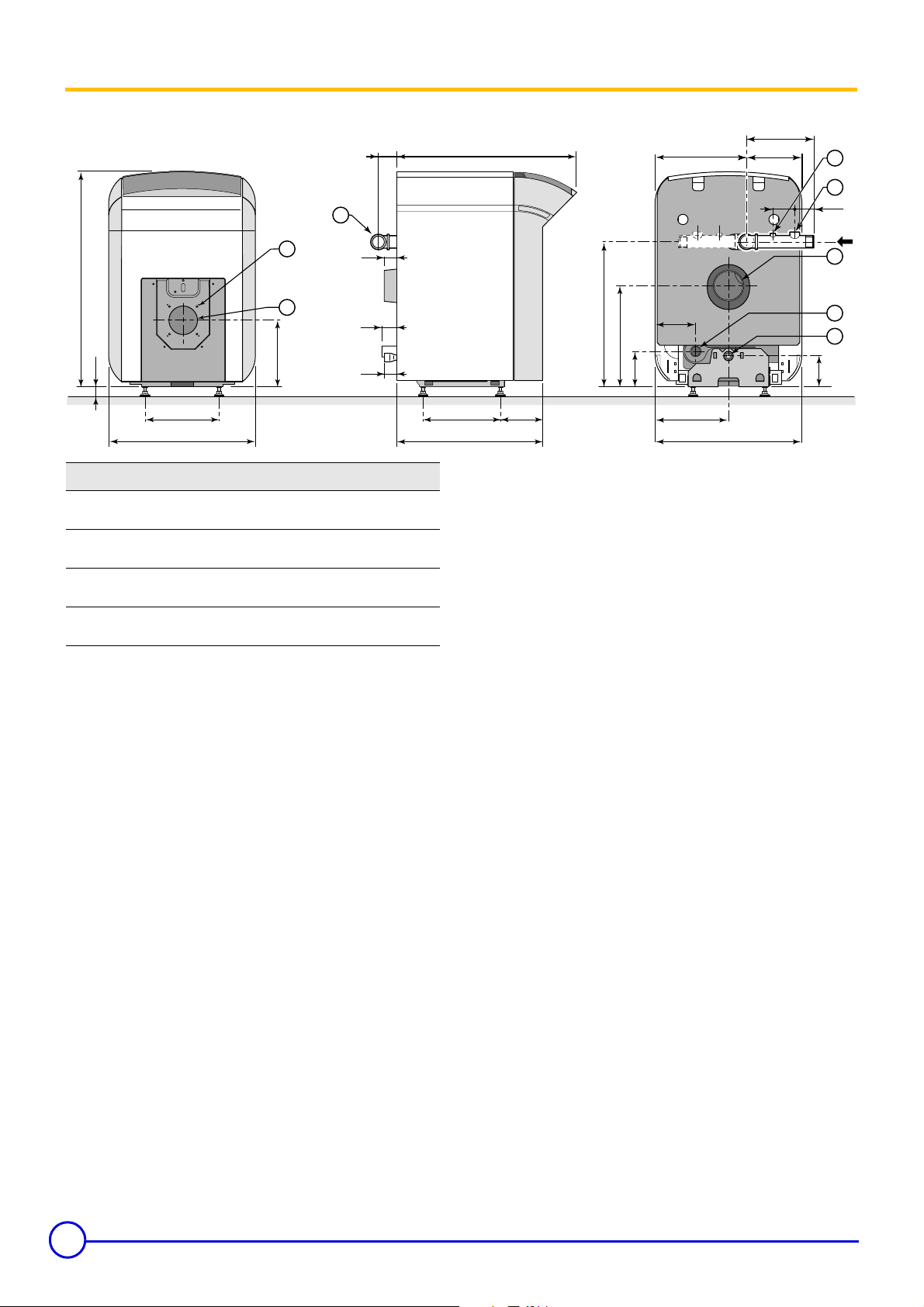
3 Main Dimensions
Note:
Dimension 'A' will be increased with applied burner, consult
burner documentation for dimensions and required service
clearance required.
• GT 120 A
3
11/16
3/8
9
B
14
7
11/16
2
7/8
32
(1)
GT
123 A
GT
124 A
GT
125 A
GT
126 A
10
11
7/16
1
3/8
11
7/16
22
10
A B øD E F
26
22
32
37
1/4
15/16
1/4
1/4
27
32
37
42 6
4
4
4
15/16
15/16
15/16
11
16
21
26
1
13/16
13/16
13/16
13/16
3/4
2
F
3/8
2
1/8
1
E
A
7/16
6
3/16
22
1/2
15
7/16
5
1/8
6
1/4
11
7/16
22
(1) Adjustable feet : basic height 1”, adjustment range 1” to 1
3
3/4
2
4
5
6
7/16
4
8578N014B
9/16
1 1 1/4 threated heating outlet
2
2 Tapping 1/4”
2
2
3 Tapping 3/4”
4 Flue gas nozzle ø D
5 1 1/4 threated heating return
7/8
3
6 1/2” tapped draining outlet
10 4 x M8 on ø 5
4 markings on ø 6
5/16
11 ø 4
1/8
cut-out
ø 5
7/8
15/16
hole
6
GT 120 A - GT 1200 A 09/02/08 - 94863361 - 85784009D
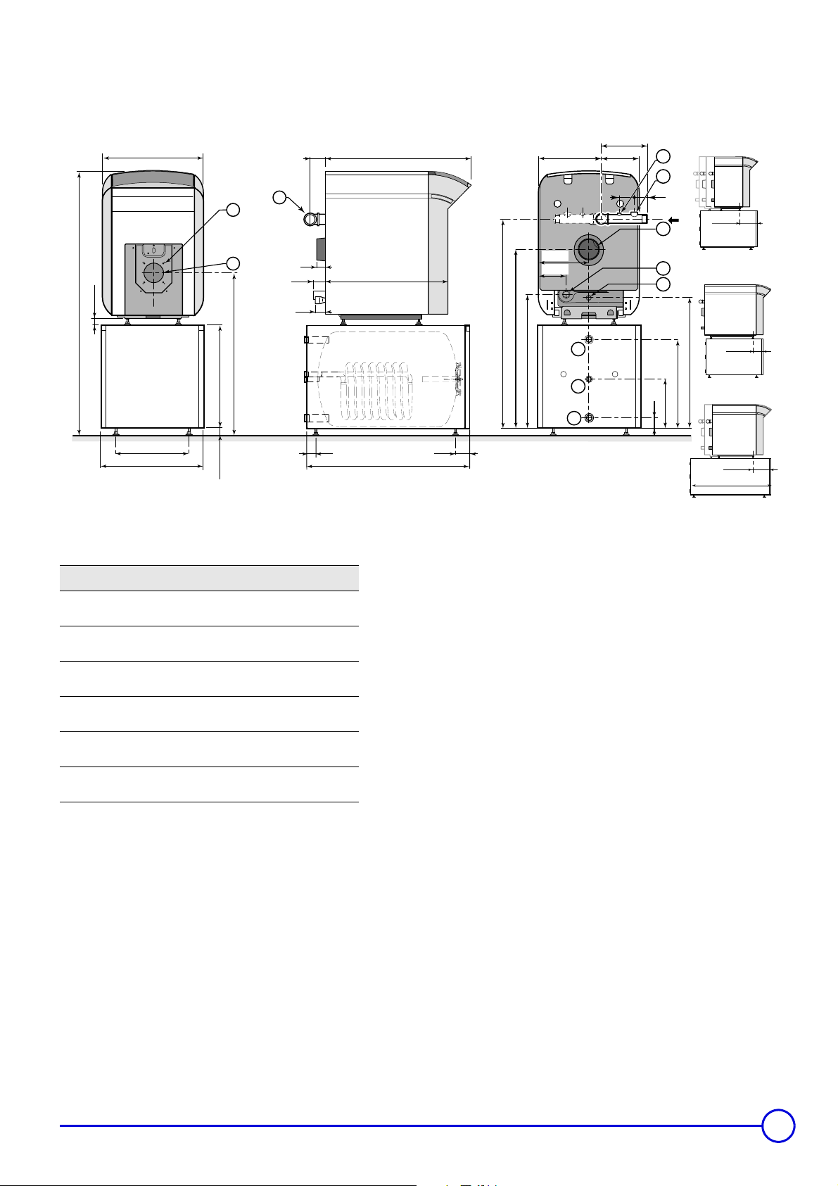
• GT 1200 A
9/16
(3)
58
3/4
22
7/16
3/8
11/16
3
10
11
1/8
36
5/8
23
1
F
3/8
2
1/8
1
B
A
1/2
46
13/16
39
14
1/4
11
1/8
6
3/4
29
7
8
9
9
11/16
7
3/423/4
2
2
3
1/8
5/16
20
1/16
29
11
GT 1203/160
GT 1204/160
GT 1205/160
1/2
6
GT 1206/160
4
5
6
1/4
3/8
11
2
GT 1203
A/160
GT 1204
A/160
GT 1205
A/160
GT 1206
A/160
GT 1205
A/250
GT 1206
A/250
1/4
19
23
5/8
(2)
3/8
1
A B øD F
26
22
32
37
32
37
1/4
15/16
1/4
1/4
1/4
1/4
27
32
37
42 7
37
42 7
4
4
4
4
15/16
15/16
15/16
15/16
1/16
2
2
2
2
7/8
3
2
7/8
3
5/8
5/8
36 (160 L.)
36
7/16
51 (250 L.)
1/4
3
3/8
(2) Adjustable feet : basic height 1
(3) Adjustable feet : feet screwed to lock at
9/16
possible
1
, adjustment range 1
3/4
adjustment from
1 1 1/4 threated heating outlet
2 Tapping 1/4”
3 Tapping 3/4”
4 Flue gas nozzle ø D
5 1 1/4 threated heating return
6 1/2” tapped draining outlet
7 Domestic hot water outlet - R 1
8 Domestic hot water circulation loop return R 3/4
9 Domestic cold water inlet - R 1
10 4 x M8 on ø 5
4 markings on ø 6
5/16
11 ø 4
1/8
cut-out
ø 5
14/16
15/16
hole
R = thread
1/8
11
1306
GT 1205/250
GT 1206/250
3/8
to 1
3/4
9/16
to
G = cylindrical external thread, leak tightness by flat washer
09/02/08 - 94863361 - 85784009D GT 120 A - GT 1200 A
7
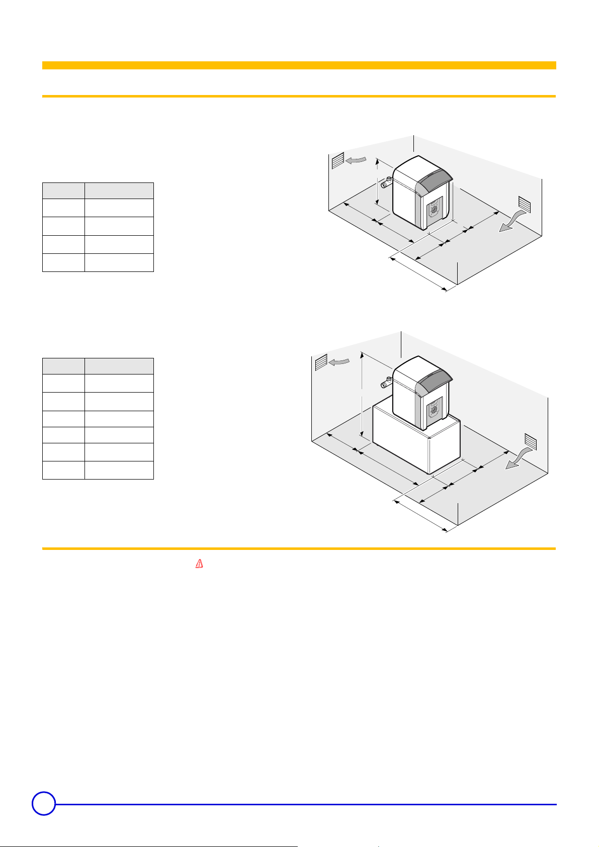
1 Location
Installation
Sufficient space shall be left clear around the boiler.
The figures stated in
inches in the drawings below are the minimum
• GT 120 A
recommended dimensions for providing easy access around the
boiler. Dimension 'X' must provide 24 inches in front of the burner for service.
Boiler A (in)
GT 123 A
GT 124 A
GT 125 A
GT 126 A
1/4
22
15/16
26
1/4
32
1/4
37
• GT 1200 A
Boiler L (in)
GT 1203 A
GT 1204 A
GT 1205 A 37
GT 1206 A 42
GT 1205 A
GT 1206 A
Floor : non combustible - do not install on carpet
10/16
36
10/16
36
7/16
51
7/16
51
33
19
A
22
19
8578N016A
19
X
19
L
23
19
8578N017A
19
X
2 Combustion air requirements
8
Warning:
• Inadequate combustion air supply will result in carbon monoxide [CO] development.
• Ensure boiler room is provided with an obstruction free combustion air source,
• Sources must be sized to provide ample supply, more than one o pening maybe required.
• Ensure boiler room must be been with adequate se rvicing clearances.
• Ensure boiler installed with proper clearance to combustible mate rials
• Do not store combustible materials, flammable fluids or vapors near the boiler.
• Do not operate the boiler under a negative building pressure.
The combustion air supply depends on the volume and construction of the building, more than one
combustion air supply source or openings maybe required. Combustion air sources that are provided by
mechanical device or electrically operated must be interlocked with the boiler/burner to ensure they are in
the correct position.
The combustion air supply must be from a source that is free from airborne contaminates such as dust,
fumes, corrosive elements, hydrocarbons and any other known air containments. If the combustion air
quality is unknown or is a concern, please consult the factory for assistance. Failure in complying with any
of these requirements will result in void of product warranty.
Particular installation areas and other equipment occupying the same room, precautions regarding the
combustion air supply and quality.
• Rural areas
• Chemical plants
• Automotive shops
• Beauty shops
• Paint shops
The combustion air supply/source must be sized in accordance to local and national codes.
Canada – CSA B149 for gas installations
Canada – CSA B139 for oil installations
Consult local building codes, for any other additional combustion air supply or source requirements.
• Agricultural
• Green houses
• Mechanical rooms
• Other fuel burning equipment.
US – ANSI Z223.1/NFPA 54 for gas installations
US – NFPA 31 for oil installations
GT 120 A - GT 1200 A 09/02/08 - 94863361 - 85784009D

The assembly of any options delivered with the boiler is described in
the instructions accompanying the options. The list of available
options is indicated in the price list in force.
Step one
Removing the front panel
Lift the window.
Unscrew the two front panel side attachment screws.
Unclip the front panel from the clips and notches near the top,
and pull it towards you.
Remove the front panel from the notches in the bottom of the side
panels.
Assembly
1
2
3
2
3
Step two
Reverse the direction of opening of the burner door if necessary
(opening at left)
When the burner leaves the factory, the burner door opens towards
the right. To open the burner door towards the left (if necessary):
- remove the front cap, then
- perform following operations: 2.1, 2.2 and 2.3.
Loosen the 2 top and bottom nuts.
Remove the lower and upper hinges.
2.1
4
8578N031
9
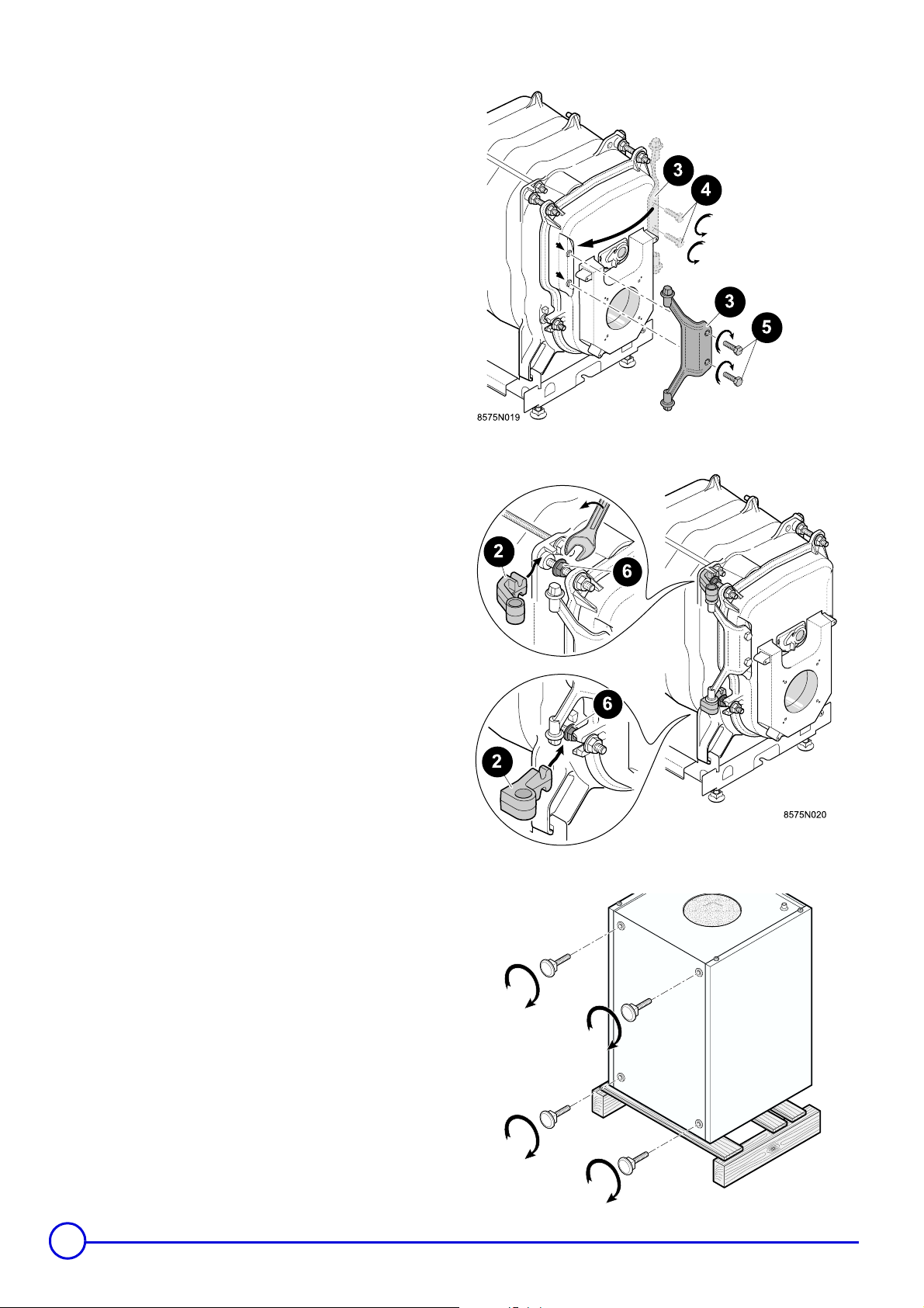
Remove the cast iron hinge pin for the burner door fixed by the 2
screws
- Reinstall the cast iron hinge pin
side using the 2 screws
. Put the two screws back on the right-hand side.
for the burner door on the left
.
2.2
- Reinstall the hinge pins
nuts located on the burner door hinge pins, on the left side, as shown
on the adjacent figure.
- Tighten the 2 nuts.
Step three
on the left side, fixing them using the
2.3
GT120A boilers can be installed on an L160 or L250 domestic
hot water tank
- perform following operations:
Fixing the feet
- Screw the 4 adjustable feet (delivered in the hot water tank
instruction packet) to the base of the tank.
10
,
and .
GT 120 A - GT 1200 A 09/02/08 - 94863361 - 85784009D
8575N046B
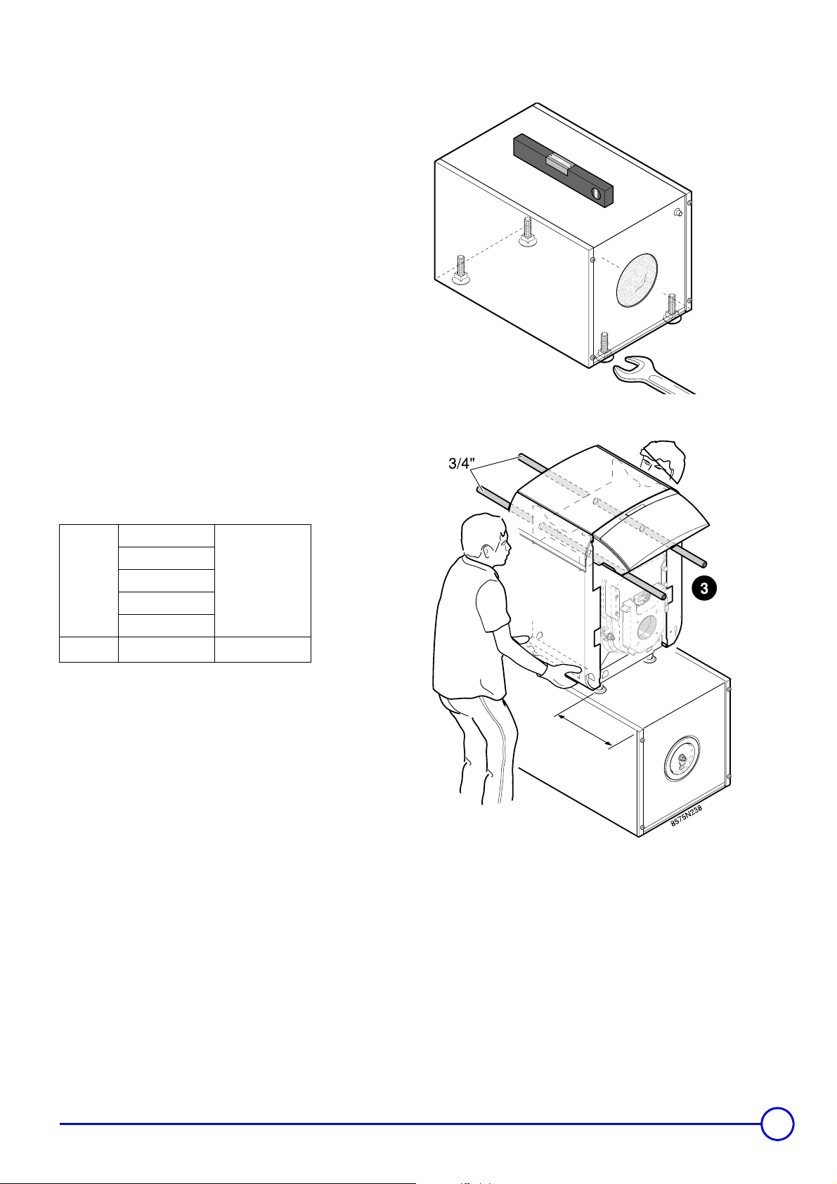
Levelling the tank
- Level the tank using the adjustable feet.
3/8
3/8
to 1
,
9/16
possible.
Base measurement 1
Adjustment from 1
Fixing the boiler on the DHW tank
Using gloves, lift the boiler using 2 ø3/4” tubes placed as shown in
the drawing, or with the two handles on the lower part of each side of
the boiler.
8575N047D
19
Boiler
P (in)
GT 1203/160
GT 1204/160
GT 1205/160
GT 1205/250
GT 1206/250
1/8
11
GT 1206/160
1/2
6
P
C
09/02/08 - 94863361 - 85784009D GT 120 A - GT 1200 A
11
Step four
The burner as supplied shall be installed according
to the manufacturers supplied documents and
installation requirements.
The fuel tank, fuel lines and filters and connection to
the burner must comply to all National and local
codes as required.
CSA B139 Oil
CSA B149 Gas
ANSI Z223 Gas
NFPA 31 Oil
The maintenance required for the burner and associated fittings, are described with each burner as supplied, consult
their documentation.
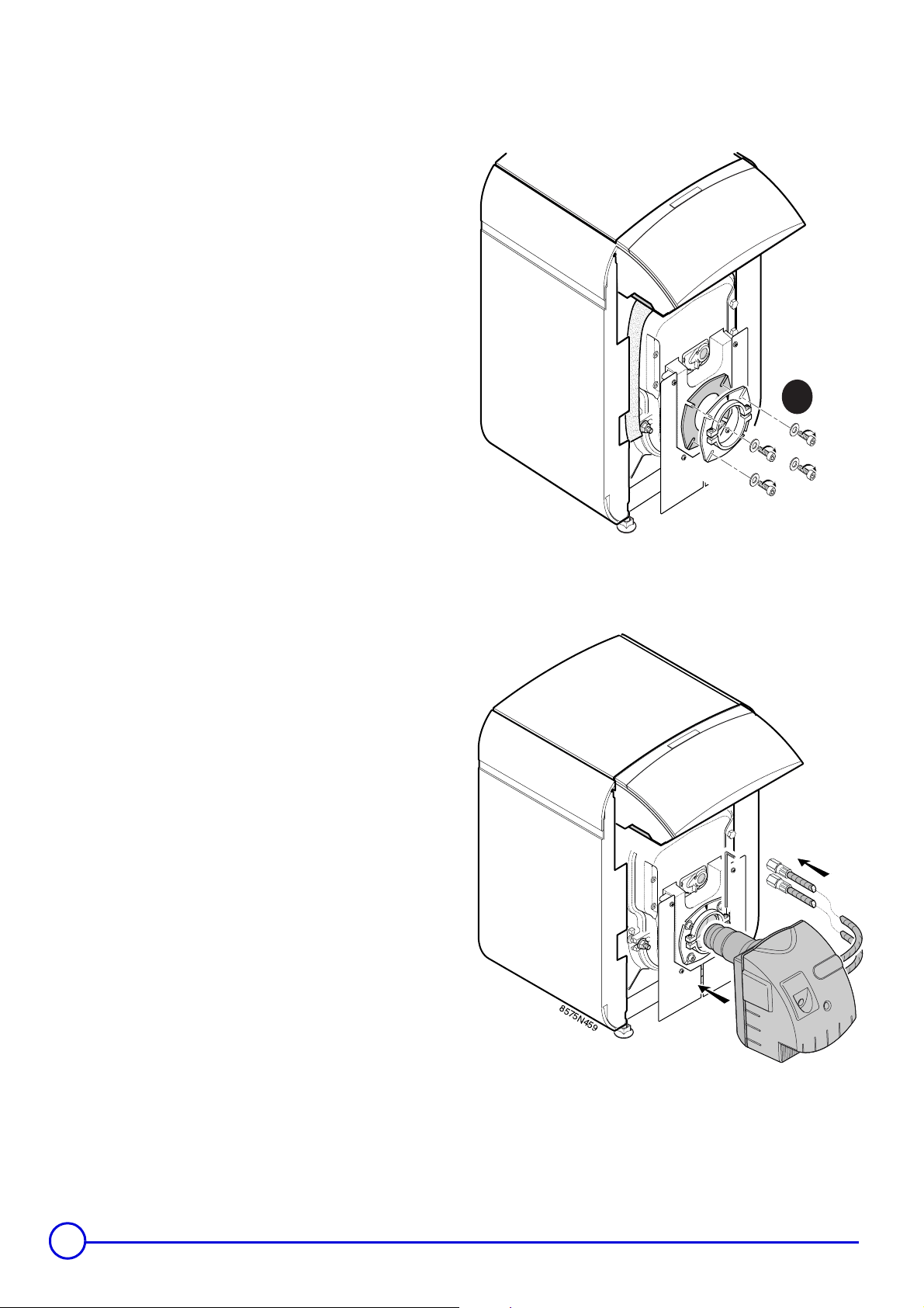
Installing the burner
- Installing the burner fixing flange
See burner manufacturer instructions for burner installation.
Diagram 4.1 is for reference only.
Burner mounting tools are not supplied.
4.1
1
8575N239C
Fixing the burner to the boiler
Note:
When the connections have been made and the installation has
been filled with water, start the burner with reference to the
instructions provided with it.
Burner shown is for demonstration purposes, only. Consult
burner manufactures installation instructions.
4.2
8575N459
12
GT 120 A - GT 1200 A 09/02/08 - 94863361 - 85784009D
 Loading...