

Page 1

EN GUIDE TO INSTALLATION AND USE
Cooking Hob
Page 2
Dear Customer,
You have just acquired a DE DIETRICH hob and we would like to thank you.
In order to offer you an excellent product, our research teams have created this new generation of appliances for you. Their quality, appearance,
functions and technological advances make them exceptional products,
showcases of our unique know-how.
In the line of DE DIETRICH products, you will also find a wide range of
ovens, microwaves, ventilation hoods, hoods, dishwashers, and refrigerators, all of which can be integrated and all of which can be coordinated
with your new DE DIETRICH hob.
Of course, in our ongoing desire to ensure our products satisfy your needs
in the best possible way, our customer service department is always at
your disposal at our site.
DE DIETRICH
Setting New Values
We are constantly improving our products; for this reason we reserve the right to make all
modifications to their technical, functional or aesthetic characteristics, originating from technical developments.
Warning
Before installing and using your appliance please read this installation and use the guide
carefully - it will help you familiarise yourself very rapidly with its operation.
2
Page 3

CONTENTS
EN
1 / INSTALLING YOUR APPLIANCE
• Installation
• Connection
2 / USING YOUR APPLIANCE
• The induction principle
• Description of your top
• Using a cooking zone
• Additional functions
Preheating
Function Boil
Delayed cooking
Independent timer
Elapsed time
Power tracker
Preselected power settings
Child safety
Clean lock
• Safety features when operating
3 / MAINTAINING YOUR APPLIANCE
4 / SPECIAL MESSAGES, DIFFICULTIES
5 / AFTER-SALES SERVICE __________________________________________________ 16
_________________________________________________________
_________________________________________________________
_______________________________________________
_______________________________________________
________________________________________________
_________________________________________________
________________________________________
_________________________________________
______________________________________
10
10
13
14
15
4
5
7
8
3
Page 4
EN
4 cm
4 cm
4 cm
Entrée d'air
Sortie d'air
4 cm
A
1 / INSTALLING YOUR APPLIANCE
L
L
4
66,,4
ir intake
A
’
ll’
v
v
e
e
n
n
t
t
i
i
l
l
a
a
t
t
i
i
o
o
n
n
s
s
p
p
a
a
c
c
e
e
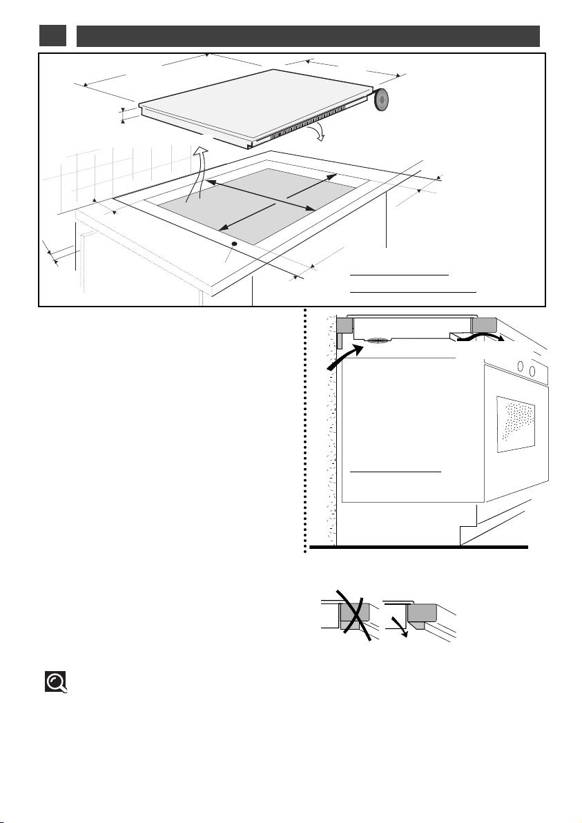
CHOOSING THE POSITION
•
•
The distance between the edge of your appliance
and the side and rear walls (or partitions) must be
at least four centimetres (zone A).
YYoouurr aapppplliiaannccee mmaayy bbee bbuuiilltt iinn wwiitthhoouutt aannyy rreessttrriiccttiioonn.. CChheecckk,, hhoowweevveerr,, tthhaatt tthhee aaiirr iinnttaakkee aanndd oouuttlleett aarree ffrreeee ooff oobbssttrruuccttiioonn ((sseeee ““ddeessccrriippttiioonn oof
yyoouurr aapppplliiaannccee”” cchhaapptteerr)).
The building-in method opposite is recommended
for use above an oven or a built-in appliance.
•
•
BUILDING-IN
Follow the diagram above.
Glue the foam seal underneath your appliance, following the perimeter of the hole in the worktop,
upon which your appliance will rest. This will
ensure a good seal against the worktop.
Attach the clips to the hob
model
).
.
(depending on the
LL’
ll
Air outlet
’
AAbboovvee aa ccaabbiinneett
wwiitthh aa ddoooorr oorr ddrraawweer
-
f
AAbboovvee aann oovveenn
r
MIN 4 mm
On 30, 38, 80 and 90 cm models, ensure that the
upper rail across the front of the cabinet does not
impede the air flow. If necessary, cut a chamfer.
Tip
If your hob is located above your oven, the hob’s thermal safety devices can impede the
simultaneous use of the hob and the oven’s pyrolysis program.
Your hob is equipped with an anti-overheating safety system.
This safety device can trigger, for example, when the hob is installed over an oven that is not sufficiently insulated. If this occurs, a series of small lines appears on the control panel. In such circumstances we recommend that you increase the hob’s ventilation by creating an opening in the
side of the cabinet, (8 x 5 cm), and/or installing an oven insulation kit available from the after-sales
department.
4
Page 5
1 / INSTALLING YOUR APPLIANCE
EN
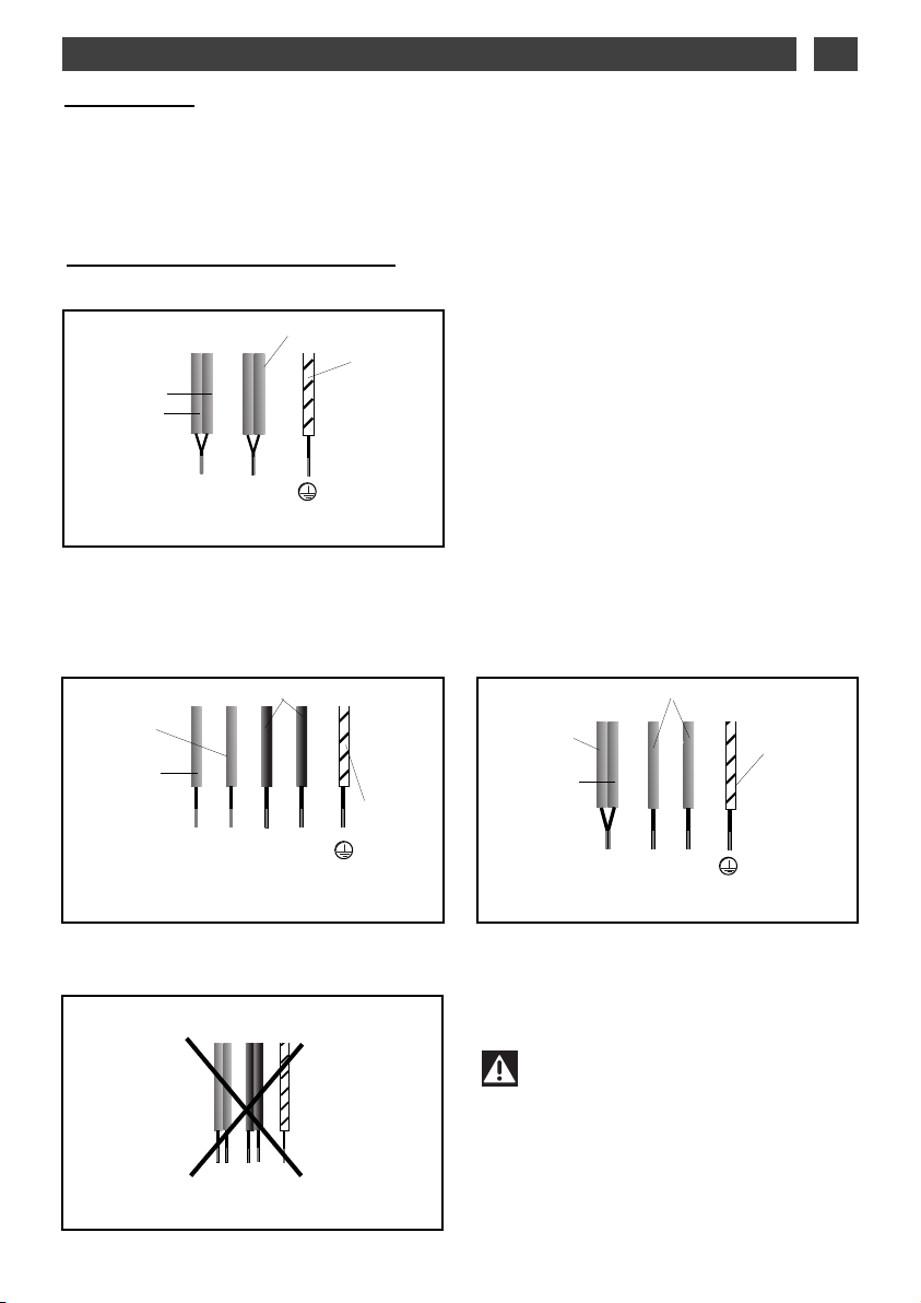
Connection
These hobs must be connected to the mains using a socket in compliance with publication CEI
60083 or an all-pole circuit-breaker device in compliance with the installation rules in force.
When power is first supplied to your hob, or after an extended power cut, an indicator light will
appear on the control panel. This information will disappear after 30 seconds.
Special connection DTI1043*
•
220-240V
32A
Blue
Brown
~
Neutral
Black or grey
Green/yellow
L
N
Phase
Earth
•
2x230V 2L+2N
Separate the wires before connection.
Brown
Blue
N1
400V 3
•
~
-
-
16A
~
Black-grey
L1
N2
Neutral EarthPhase
16A
Green/yellow
L2
•
400V 2N
Separate the 2 phase wires (L1 and L2) before
connection.
Brown
Blue
With hook-up of 400 V 2N three phase, verify
that the neutral wire is properly connected.
16A
-
~
Black-grey
L1
N
Neutral EarthPhase
Green/yellow
L2
Warning
If the cable is damaged it must be
replaced by the manufacturer, its aftersales service or a person with a similar
qualification to prevent danger.
5
Page 6
EN61 / INSTALLING YOUR APPLIANCE
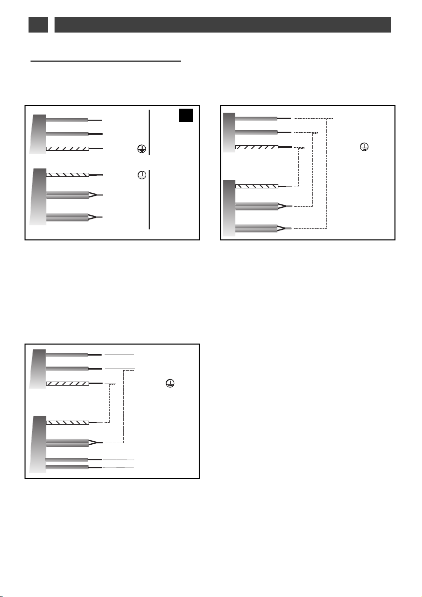
Special connection DTI1049*
•
220-240 V monophase hook-up
116
332
6
2
and
amp fuses.
663
3
amp fuse.
Brown
lue
B
Green/yellow
Green/yellow
Blue
Brown
Black-grey
400 V 3N triphase hook-up
•
PPhhaasse
NNeeuuttrraal
GGrroouunnd
GGrroouunnd
NNeeuuttrraal
PPhhaasse
e
L
L
l
N
N
d
d
l
N
N
e
L
L
1166 A
3322 A
A
A
A
A
Séparate the two phase wires L2, L3 before
hooking up.
116
6
amp fuse.
Brown
Blue
Green/yellow
PPhhaasse
NNeeuuttrraal
GGrroouunnd
e
LL1
1
l
N
N
d
Brown
lue
B
reen/yellow
G
Green/yellow
Blue
Brown
Black-grey
PPhhaasse
NNeeuuttrre
TTeerrrre
e
L
L
e
N
N
e
Green/yellow
Blue
Brown
Black-grey
PPhhaasse
PPhhaasse
LL2
2
e
e
LL3
3
If the unit has a 3 phase 400 V3N connection, and is not working correctly, check that
the neutral wire is correctly connected.
Page 7

2 / USING YOUR APPLIANCE
+
-
CC
BB
AA
We have designed this cooking hob for use by private individuals in their homes.
These cooking hobs are intended exclusively for cooking beverages and foodstuffs and do not
contain any asbestos-based materials.
This appliance is not intended to be used by persons (including children) with reduced physical,
sensory or mental abilities, or persons lacking experience or awareness, unless using it with the
help of a person reponsible for their safety, or under supervision and with prior instruction in its
use. Children should be supervised to ensure that they do not play with the appliance.
EN
• The induction principle
The principle of induction is based on a magnetic effect.
When you place your cookware on a cooking
zone and you turn it on, the electronic circuits
in your cooking hob produce “induced” currents in the bottom of the cookware which
instantly raise its temperature. This heat is
then transmitted to the food
To help you choose, a list of cookware is provided with this guide.
A - Induction plate
B - Electronic circuit
C - Induced currents
• Cookware
Most cookware is compatible with induction.
To verify that your cookware is suitable, place
it on a heating area (16 or 23cm) on power 4.
- If the display remains on, your cookware is
compatible.
- If the display flashes, your cookware cannot
be used with induction cooking.
You can also use a magnet to test the cookware.
If a magnet “sticks” to the bottom of the cookware, it is compatible with induction.
Only glass, terra cotta, aluminium without a
special finish on the bottom, copper and some
non-magnetic stainless steels do not work
with induction cooking. We recommend that
you select cookware with a thick, flat bottom.
When you buy your cookware, make sure that
this logo is on the package; it assures you that
it is compatible with induction cooking.
•Choosing a cooking area
Cooking
area
16 cm 10 ..... 18 cm
23 cm 12 ..... 26 cm
28 cm 12 ..... 32 cm
Front or rear
ONTINUUM
C
Complete
ONTINUUM
C
7
Diameter of base
of cookware
12 .....20 cm
v
8 ..... o
1
ish kettle
al, f
Page 8

EN
2 / USING YOUR APPLIANCE
Description of your top
DDTTII11004433*
BAC
*
50 W à 3600 W
D
TToottaall ddiimmeennssiioonnss ((LL xx l)) --
DTI1043* : 65 x 50.7
RReecceessss ccuutt--oouutt ((LL’’ xx l’’))
DTI1043* : 56 X 49
2233 ccm
m
50 W à 3200 W
DDTTII11004433XX::
50 W à 4600 W
1166 ccm
m
50 W à 2200 W
F
E
G
H
I
K
J
L
•Adjustment touch controls
Use these touchpads to select, turn on and
turn off the cooking zones. When a zone is
selected, you will see it light up, and you can
adjust its settings.
A
A
front CONTINUUM zone
B
B
rear CONTINUUM zone
C
C
complete CONTINUUM zone
E
E
zone 16 cm.
F
F
zone 23 cm.
FFoorr aa sseelleecctteedd zzoonne
Indicator for
selected zone
e
Power displa
y
Timer
displa
y
•Adjustment touch controls
These touchpads allow you to adjust power,
timer, programmer... for each of the selected
zones.
D
D
adjusting the power
GG
function
HH
function
II
preselecting the power
JJ
adjusting the timer
KK
function
LL
locking - unlocking - Clean lock
If there is no cookware on the selected zone,
our adjustments will delete automatically after
y
a few moments.
8
BOIL
POWER TRACKER
ELAPSED TIME
Page 9

2 / USING YOUR APPLIANCE
EN
DDTTII11004499*
TToottaall ddiimmeennssiioonnss ((LL xx l))
DTI1049* : 93 x 50.7
RReecceessss ccuutt--oouutt ((LL’’ xx l’’))
DTI1049* : 90 x 49
*
50 W à 3600 W
BAC
D
2288 ccm
m
50 W à 3600 W
M
1166 ccm
m
0 W à 2200 W
5
2233 ccm
m
50 W à 3200 W
DDTTII11004499XX::
50 W à 4600 W
F
E
G
H
I
J
K
L
•Adjustment touch controls
Use these touchpads to select, turn on and
turn off the cooking zones. When a zone is
selected, you will see it light up, and you can
adjust its settings.
A
A
B
B
C
C
M
M
E
E
FF
FFoorr aa sseelleecctteedd zzoonne
Indicator for
selected zone
ONTINUUM zone
front C
ONTINUUM zone
rear C
complete C
zone 28 cm.
zone 23 cm.
zone 16 cm.
ONTINUUM zone
e
Power display
Timer
display
•Adjustment touch controls
These touchpads allow you to adjust power,
timer, programmer... for each of the selected
zones.
D
D
adjusting the power
GG
function
HH
function
II
preselecting the power
JJ
réglage de la minuterie
KK
function
L
L
locking - unlocking - Clean lock
If there is no cookware on the selected zone,
your adjustments will delete automatically after
a few moments.
9
BOIL
POWER TRACKER
ELAPSED TIME
Page 10

EN
2 / USING YOUR APPLIANCE
F
E
BA C
D
G
H
K
I
J
L
Using a cooking zone
Adjusting the power level:
- Place your cookware on the cooking zone
and press the corresponding touchpad A,
B, C, E, F or M. A beep and a light will confirm your selection.
- Adjust the power with the touchpads D, I.
- To switch off the cooking zone keep your
finger pressed on the touchpad.
Adjusting the timer:
- Select a cooking zone.
- Adjust the timer using touchpad J.
- When the cooking is finished, “0” is displayed and a beep sounds. Press on the
main selector to delete this information.
N.B.:
- The first touch on J “–” directly selects
99 minutes.
- Simultaneous touch on J “+” and “–” annuls
the timing in progress.
- If you do not make a selection or if there is
no cookware, the selected zone turns off
after a few moments.
Additional functions
•Preheating
This function allows it to reach a high temperature more rapidly, then return automatically
to cooking power.
- Select a cooking zone
- Turn on preheating with the touchpad D “-”,
HU is displayed on your hob.
- Pre-adjust the cooking power with touchpad D (higher than 7). A beep confirms your
adjustment after a few moments. Cooking
starts.
- During the pre-heating stage, HU and the
cooking power display alternately.
- After the pre-heating stage, your hob displays the cooking power.
N.B.:
- The pre-heating time is calculated automatically by your hob depending on the cooking
power level chosen.
- When HU is displayed, if you do not adjust
the cooking power, the zone turns off after a
few moments.
• BOIL
This function allows water to be boiled and
kept at boiling point to cook any food that
requires boiling.
G
G
- Give a short press on button
hear a short beep. “2l” (2 litres) id displayed
as the default.
- Adjust the volume of water to between 0.5
and 6 litres, using the + and – buttons (
The quantities of water are 0.5l, 1l, 1.5l, 2l,
2.5l, 3l, 4l, 5l and 6litres.
- Give a short press on button
the selection. A short beep sounds and the
bbooiil
l
” display stops flashing.
“
Once the water has boiled, a series of beeps
is heard and the word “boil” scrolls through
b
o
b
o
, then
the display (
- add the food (pasta, rice etc.). Give a short
press on button
is displayed by default.
Adjust the time, using the buttons
wish, you may alter the power via the buttons
D
D
.
The settings are confirmed automatically
after a few seconds or by pressing button
A short beep sounds.
NNOOTTEE:: IItt iiss iimmppoorrttaanntt tthhaatt tthhee wwaatteerr tteemmppeerraattuurree iiss nneeiitthheerr ttoooo hhoott nnoorr ttoooo ccoolldd wwhheen
ccooookkiinngg bbeeggiinnss,, aass tthhiiss ccoouulldd aaffffeecctt tthhee ffiinnaal
rreessuulltt.
.
TThhiiss ffuunnccttiioonn mmaayy bbee uusseedd oonn aallll ccooookkiinng
zzoonneess aatt tthhee ssaammee ttiimmee.
DDoo nnoott uussee ccaasstt iirroonn ccooookkwwaarree.
DDoo nnoott uussee aa lliidd.
DDoo nnoott uussee ssaalltt.
, etc...)
G
G
. Power 12 or 13 and 1 min
.
.
.
. You will
G
G
to confirm
J
J
. If you
.
D
D
).
G
G
n
g
.
-
l
10
Page 11

2 / USING YOUR APPLIANCE
F
E
BAC
D
G
H
EN
K
I
J
L
•Delayed cooking
This function allows you to delay your cooking
(available only for the S
Program delayed cooking in 6 steps:
1 - Select the cooking zone dedicated to this
function.
2 - Press simultaneously on touchpads J “+”
and “–” to adjust the current time of your
hob. When the numbers flash, you can
adjust the hour with the touchpad J, then
wait a few moments. If the hour displayed
is correct, wait a few moments. The display
will stop flashing and a beep will confirm
the setting.
3 - Set the end of cooking time by pressing on
touchpad J. Wait a few moments. A beep
will confirm your setting.
4 - Set the duration of cooking time by press-
ing on touchpad
beep will confirm your setting.
5 - Set the power of your cooking by pressing
on touchpad
(maximum 6). Wait a few moments. A beep
will confirm your setting and SC is displayed on your hob.
6 - After a few moments, SC goes out and a
flashing point appears to indicate that
delayed cooking has been engaged.
TART CONTROL zone).
J. Wait a few moments. A
D, 4 is displayed by default
•Elapsed time
This function displays the time elapsed since
the last power setting adjustment on a chosen zone.
K
K
To use this function, press the
elapsed time flashes on the timer display of
the selected zone.
If you want cooking to end in a specific period, press button
“+” on the timer to increase the cooking time
that you wish to set. The time display
becomes steady for 3 seconds then the
remaining time is displayed. There is a beep to
confirm your choice.
This function exists with or without the timer
function.
Note: If a time is displayed on the timer, this
time cannot be changed during the 5 seconds
after pressing the
onds have elapsed, you may change your
cooking time.
K
K
then, in 5 seconds, press
K
K
button. Once these 5 sec-
button. The
•Independent timer
This function allows you to time an event, without cooking.
- Select a cooking zone you are not using.
- Set the time with touchpad J. A “t” flashes in
the display.
- At the end of your adjustment “t” becomes
becomes fixed and the count begins.
Note:
You can stop a count in progress by keeping
your finger on the touchpad of the selection
on the display.
11
Page 12

2 / USING YOUR APPLIANCEEN
•Power tracker
This function lets you move a pan from one
zone to another, keeping the original settings
(power level and time).
1 - Press on button
sounds then the pan is moved to the new
zone.
2 - Press on button
displayed on the new zone. The original
cooking zone switches off when the settings are displayed on the new zone.
- If there is no pan before button
pressed, a long beep sounds and the function is cancelled.
- If button
pan is moved, the function is cancelled and
NO appears in the display.
If you move a pan from a complete cooking
zone to another complete cooking zone, the
function is cancelled and
display.
If the “Power tracker” function activates more
than one new zone, the function is cancelled
and
H
H
NNO
O
appears in the display.
HH,
,
and a short beep
HH
again; the information is
H
H
is pressed and more than one
NNO
O
appears in the
•Preselected power settings
This function allows you to modify the power
levels defined in the preselections (except for
the boost).
- Your cooking hob must be turned off.
- Select the preselection
ing your finger on it.
- Set the new power setting by pressing on
touchpad
- A beep will confirm your action after a few
moments.
N.B.
The power levels must be between:
D.
:
- 1 and 5 for the first touch.
- 6 and 10 for the second.
- 11 and 15 for the third.
I to modify, by keep-
•Child safety
This functioin allows you to lock your hob
when it is shut off or when it is cooking.
To lock:
- Keep your finger on touchpad L. A beep
sounds and an indicator appears. The indicator will go out automatically after a few
moments.
To unlock:
- Keep your finger on touchpad L. A beep
sounds and the indicator goes out.
Note:
is
- In locked mode, any action will produce a
key symbol on the display. You must unlock
your hob before using it.
- If you activate the lock while cooking, the
stop display will be prioritised on the lock.
•Clean lock
This function allows you to temporarily lock
your hob while cleaning.
To activate Clean lock:
- Your cooking hob must be turned off.
- Briefly press touchpad
and an indicator appears.
- After a predefined time, the lock will automatically disengage. A beep sounds and the
indicator goes out.
L. A beep sounds
12
Page 13

2 / USING YOUR APPLIANCE
As shown in this logo, the materials used to package this appliance are not recyclable. Recycle them and play a role in protecting the environment by depositing them
in municipal containers provided for this purpose.
Recycling of the appliances organised by your manufacturer will thus be undertaken
in optimum conditions, in accordance with European directive 2002/96/CE relating
to electrical and electronic equipment waste. Contact your local authority or retailer
for how to have used appliances collected or collection points.
EN
Safety when operating
•Residual heat
After a long cooking period, the zone used
can remain hot for several minutes. An ‘’H’’
flashes during this period. Do not put your
hand on the zone.
•Temperature limiter
Each cooking zone is equipped with a safety
sensor that constantly monitors the temperature of the bottom of the cookware. If you
leave empty cookware on a zone which is
turned on, it will automatically limit the power
in order to prevent damage to the cookware
or hob.
• Protection against overflows
In case of overflow, or of a metallic object or
wet cloth placed on the control areas, the hob
turns itself off, the displays light up and a
beep sounds. Clean the hob or remove the
object, then begin cooking again.
•Auto-Stop system
If you forget cooking is in progress, after a
predefined time, this safety function will automatically turn off your hob (from 1 to 10 hours
depending on the power setting). “
plays and a beep sounds after about 2 minutes. Press on the main selector to delete this
information. A beep will confirm your setting.
AAS
S
” dis-
• “Small Items” safety
If you place a small object on the area (a ring,
a fork, etc), the hob will detect it and not deliver any power. The power display flashes.
Note:
However, several small objects at the same
time on a zone could be identified as cookware. In that case, power will be delivered by
the hob.
Do not place any utensils (spoons,
forks, covers, etc) on the cooking
zone being used. They will heat up in the
same way as cookware:
Risk of combustion.
•For users with heart pacemakers and active implants.
The functioning of the hob conforms to current electromagnetic interference standards and thus
is in total compliance with legal requirements (89/336/EEC directives).
In order to avoid interference between your cooking hob and a pacemaker, your pacemaker
must be designed and programmed in compliance with the regulations that apply to it.
As we can guarantee the compliance only of our own products, we strongly recommend that
you refer to the maker of your device or to your doctor to avoid possible incompatibilities.
13
Page 14

EN
3 / MAINTAINING YOUR APPLIANCE
Preserve your appliance
The vitroceramic glass surface is highly
resistant, but not unbreakable. Here are some
recommendations for increasing its lifetime:
- Avoid banging or clattering the cookware.
- Avoid putting heating covers on the hob. A
suction effect may damage the vitroceramic
surface.
- Do not use cookware with bottoms that are
rough or dented.
- Do not use your cooking hob as a work surface.
- Never use aluminium foil or paper or aluminium scrubber to clean it. The aluminium
melts and damages the top.
- Never use a steam cleaner to clean your
hob.
Maintaining your appliance
- Never directly reheat a tin can. It will have a
risk of exploding.
Aesthetic faults, as a result of mistreatment of
your hob and which do not entail a lack of
function, are not covered by our guarantee.
And for the safety of your kitchen, do not
place cleaning items or inflammable objects
or products in the kitchen furniture underneath your cooking hob.
TYPES OF STAINS/SPOTS
Light.
Accumulation of baked-on
stains/dirt.
Sugar spills, melted plastics.
Rings and hard water
residue.
Shiny metal colourings.
Weekly maintenance.
cream
cleaning sponge
special for delicate crockery
USE
Cleaning sponges
Cleaning sponges
Scraper for glass.
White vinegar.
Special vitroceramic glass product.
14
WHAT TO DO?
Thoroughly moisten the zone to be
cleaned with hot water, then wipe off.
Thoroughly moisten the zone to be
cleaned with hot water. Use a scraper for
glass to remove the large bits, follow with
the rough side of a disinfectant sponge,
and then wipe off.
Apply warm white vinegar to the stain, let
stand, then wipe with a soft cloth.
Apply a cleaning agent for vitroceramic
glass (preferable one with silicon for its
protective properties) to the surface.
powder
abrasive sponge
Page 15

4 / SPECIAL MESSAGES, DIFFICULTIES
•On first use
POSSIBLE CAUSES:
A special lamp appears.
Your installation blows a fuse.
Only one side works.
The hob produces an odour dur-
Working normally.
The electrical connection of
your hob is incorrect.
New appliance.
ing the first cooking sessions.
•On switching on
YOU OBSERVE THAT: POSSIBLE CAUSES:
The hob does not operate and
the indicator lights on the control panel do not light up.
The hob is not working and
another message is displayed.
The hob does not function, the
The machine is not connected to
the power source. The power
source or connection is defective.
The electronic board is functioning poorly.
The hob is locked
information is displayed.
•While in use
EN
WHAT SHOULD YOU DO?
Nothing, the light disappears
after 30 seconds.
Check that it is set up
properly.
See the “Electrical
Connection” section.
Nothing. The smell will disappear after several uses.
WHAT SHOULD YOU DO?
Inspect the electrical circuit breaker and fuses.
Call the After-Sales
Service Department.
See chapter on using the
child safety system
YOU OBSERVE THAT: POSSIBLE CAUSES: WHAT SHOULD YOU DO?
The hob has stopped operating and is
beeping approximately every 10 seconds and a or F7 is displayed.
A series of small or F7 is displayed.
ter turning on a heating zone, the
Af
or lights on the control panel
indicat
continue to flash.
The saucepans make noise during
cooking.
Your hob makes a clicking sound during cooking.
The fan continues to function a few minutes after your hob is turned off.
After turning on a heating zone, t
indicator lights on the contr
remain steady but the cookware is not
heated.
ol panel
There was an overflow or an
object is in contact with the
control panel.
The electronic boards heated
up.
The cookw
able f
than 12 cm in diameter (10 cm
on a 16 cm area).
This is normal with some
types of cookware. This is
caused by the transfer of
energy from the hob to the
cookware.
Cooling of the electronic components.
W
he
The cookw
suit
tion.
are used is not suit-
or induction or is less
king normally.
or
e used is no
ar
or use wit
able f
h induc
Clean the hob or remove the
object, then begin cooking
again.
See “Inserting” section.
See section on cookw
induction.
Nothing. There is no risk, neither to your hob nor to your
cookware.
Nothing.
t
See section on cookw
-
induction.
are for
e f
ar
or
15
Page 16

EN
Any maintenance on your equipment should be undertaken by:
- either your dealer,
- or another qualified mechanic who is an authorized agent for the brand appliances.
When making an appointment, state the full reference of your equipment (model, type and serial
number). This information appears on the manufacturer's nameplate attached to your equipment.
For UK after sales service information please contact:-
De Dietrich UK office – tel: 01256 308000
5 / AFTER-SALES SERVICE
www.dedietrich.co.uk
In case of breakage, cracks or even light fissures in the vitroceramic glass, take out
the fuses or turn off the circuit breaker for your hob to avoid the risk of electrical
shock.
Contact the After-Sales Service Department.
16
Page 17

DE DIETRICH COOKING PRODUCT
WARRANTY
1. Subject to the “Statement of Standard
W
arranty Conditions” this product is
covered by the following Warranty.
T
WO (2) YEARS WARRANTY from
date of purchase, covering all parts
and labour.
2. The appliance is warranted under normal
single family domestic installation and
use, as set out in the instruction manual,
against manufacturing defects for the
Warranty periods shown above.
3. Should service be required under this
Warranty, the purchaser should contact
an approved DE DIETRICH Service
Provider during their normal business
hours.
4. At no time does DE DIETRICH/MEA
have liability for any freight or
transportation costs or for any damage
during transit or for any consequence of
failure of this appliance outside of the
normal service area, unless such
limitation of liability is prohibited by
statute.
5. This Warranty excludes replacement of
parts required due to normal wear and
tear including light globes.
6. This Warranty only applies, provided the
appliance has been used in accordance
with the manufacturer’s instructions and
provided an accident, misuse, neglect or
abuse has not damaged the appliance.
7. None of the above Warranties purport to
exclude, restrict or modify either the
application or the exercise of a right
conferred by any applicable Statute.
8. Please complete the details below, which
should be retained for future reference
along with your proof of purchase:
Date of Purchase: ……………………………..
Model No: ……………………………………….
Serial No: ………………………………………..
MEA0702
STATEMENT OF STANDARD
W
ARRANTY CONDITIONS
1. The Warranty only applies provided that
the appliance has been used in
a
ccordance with the manufacturer’s
instructions and provided that the
appliance has not been damaged by an
accident, misuse, neglect or abuse of any
person other than the manufacturer or
DE DIETRICH/Major Electrical
Appliances (“MEA”) or from faulty
installation, mis-adjustment or tampering
by unauthorised persons.
2. When a service inspection reveals the
alleged fault or faults are caused by
incorrect operation, contrary to the
instruction manual, and otherwise the
appliance is in good order and working
condition, the purchaser shall be liable for
aservicefeechargedbyDE
DIETRICH/MEA or one of its’ Service
Providers.
3. If the appliance is used in Commercial
Applications or for Rental purposes, a
separate warranty of Twelve (12) months
covering all parts with Three (3) months
on the labour will apply.
4. Subject to the provisions of any
applicable statute this Warranty applies
to the original retail purchaser only and is
not transferable.
5. Subject to the provisions of any
applicable statute, at no time does DE
DIETRICH/MEA have liability for freight,
transport or travel costs outside normal
service areas.
6. None of the above Warranties purport to
exclude, restrict or modify either the
application or the exercise of a right
conferred by any applicable statute.
7. Subject to any Warranties implied by
statute, at no time will DE
DIETRICH/MEA or its’ Service Providers
be liable for any economic loss
consequent upon the failure of the
appliance.
8. This Warranty is only valid for major
appliances imported and distributed by
DE DIETRICH/MEA, purchased and used
in Australia.
FFaaggoorrBBrraannddtt SSAASS,, MMaannaaggeemmeenntt ccoommppaannyy –– SSAASS:: ssoocciiaall ccaappiittaall ooff 2200,,000000,,000000 eeuurrooss RRCCSS NNaanntteerrrree 444400330033119966.
17
.
Page 18

CZ5700312 /00 - 03/10
 Loading...