

Page 1
31
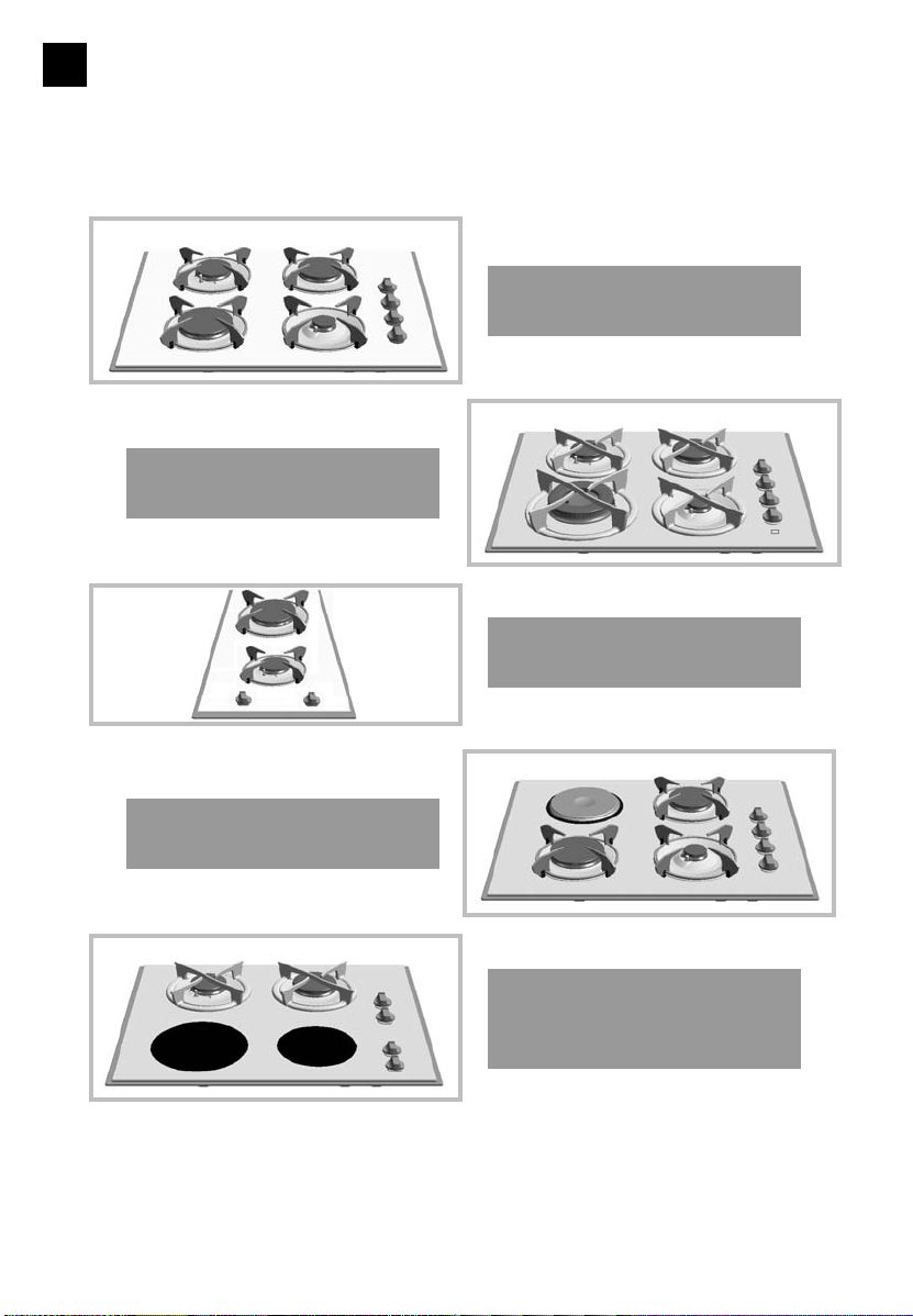
Hob operating guide
Model with 4 gas rings and
extra fast burner
Model with 2 gas rings
Model with 4 gas rings, timer
and double crown burner
Model with 2 gas rings
1 radiant ring 1 halogen ring
Model with 3 gas rings
and 1 electric ring
GB
Page 2

In this Manual,
displays safety instructions
displays tips and hints
List of contents
Using your hob in complete safety 34
What your hob looks like? 35
Installing your hob in all simplicity 36
Fitting recommendations 36-38
Electrical connections 39
Gas connections 40-42
Changing the type of gas supply 43-49
Using your hob in all simplicity 50
How to use your gas burners 50
How to use the timer 51
Which pans are best adapted for use
on the gas burner? 52
How to use the radiant and halogen rings 53
Which pans work best on a radiant/halogen ring? 54
How to use the electric hotplate? 55
Which pans are best adapted for use on the electric hotplate? 55
How to look after your hob? 56
Minor troubleshooting 57
Gas-cooking guide 58
Cooking guide for radiant/halogen rings 59
Cooking guide for electrical hobs 60
32
Page 3

33
Dear Customer,
Thank you for buying a DE DIETRICH hob.
Our research teams have designed a new generation of kitchen
appliances. As a result of our unique expertise, we have produced
a range of goods whose quality, design and technical advance are
unsurpassed.
You will find that the clean lines and modern look of your
DE DIETRICH hob blends in perfectly with your kitchen décor. It
is easy to use and performs to a high standard.
DE DIETRICH also makes a range of products that will enhance
your kitchen such as hobs, extractor hoods, built-in dishwashers
and refrigerators. There are models to complement your new DE
DIETRICH hob.
Of course, we make every effort to ensure that our products meet
all your requirements, and our Customer Relations department is
at your disposal, to answer all your questions and to listen to all
your suggestions (see back cover of manual).
DE DIETRICH is certain that by setting new standards of
excellence by which comparisons can be made, customers will
find that DE DIETRICH appliances offer a better and more
exciting way of living.
DE DIETRICH.
Editorial
Page 4

Your hob in complete safety
34
Using your hob in complete safety
YOUR HOB IS DELIVERED PRE-SET FOR USE WITH NATURAL TOWN GAS.
We have designed your hob for
private domestic use.
With a view to the constant
improvement of our products, we
reserve the right to make any
changes in their technical, functional
or aesthetic characteristics as a result
of technical evolution.
These hobs are designed exclusively
for the cooking of drinks and
foodstuffs. These products do not
contain any asbestos-based
component parts.
You must always keep an eye on your
cooking.
Please read the instructions before
installing and using this appliance.
Should a crack appear on the
glass, disconnect your
appliance immediately and
contact your After-Sales
Service.
Never leave any
CLEANING OU
INFLAMMABLE
products in the cupboard
or drawer beneath your hob (aerosols
or other pressurised cans, papers,
recipe books, etc.).
Using a gas-powered hob produces
both heat and humidity in the room
where it is used. Make sure your
kitchen is well ventilated.
Disconnect your hob from both
electrical and gas supplies before
carrying out any maintenance
operations.
For safety reasons, do not forget to
close the main gas valve for built in
gas lines or the valve on the top of
your butane/propane gas cylinder.
If a knob is difficult to turn,
DO NOT
FORCE IT
. Call up your installer.
The EC mark of conformity can be
found on all these hobs.
Page 5
35
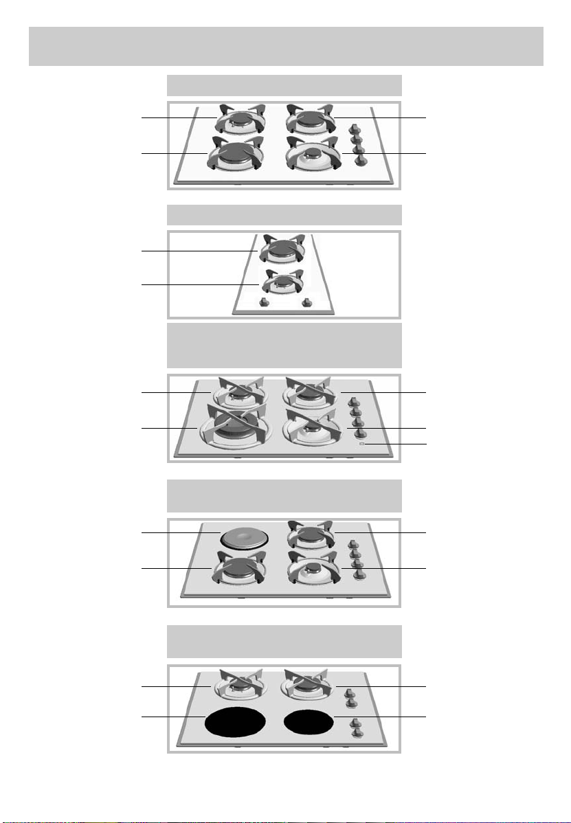
What your hob looks like?
65 cm model with 4 gas burners
Semi-fast burner
(1.50 kW*)
Induction ring
(3.10 kW*)
Fast burner
(2.30 kW*)
Auxiliary burner
(0.85 kW*)
65 cm model with 4 gas burners
and a timer with double-crown
65 cm model with 2 gas burners
1 radiant ring + 1 halogen ring
65 cm model with 3 gas burners
+ 1 electric hotplate hob
* Power obtained using G20 natural gas.
Semi-fast burner
(1.50 kW*)
Double-crown burner
(4 kW*)
Fast burner
(2.30 kW*)
Auxiliary burner
(0.85 kW*)
Timer
Semi-fast burner
(1.50 kW*)
Halogen ring
(Ø 200 mm - 1800 W)
Extra fast burner
(3.10 kW*)
Radiant ring
(Ø 165 mm - 1200 W)
Electric hotplate hob
(Ø 145 mm - 1500 W)
Extra fast burner
(3.10 kW*)
Fast burner
(2.30 kW*)
Auxiliary burner
(0.85 kW*)
30 cm model with 2 gas burners
Semi-fast burner
(1.50 kW*)
Extra fast burner
(3.10 kW*)
Page 6
This appliance should be
installed by a qualified
technician / installer.
Prior to installation, ensure that
the local distribution conditions
(nature of the gas and gas
pressure) and the adjustment
conditions of the appliance are
compatible.
The adjustment conditions are stated
on a label in the wallet and also on
the packaging.
Since this appliance is not connected
to a combustion products evacuation
device, it must be installed in
accordance with current installation
regulations and used in a wellventilated place. Particular attention
should be given to the relevant
requirements regarding ventilation.
Installing your hob in all simplicity
36
On this subject, combustion can take
place only if oxygen from the air is
present, so this air must be
constantly renewed and the
combustion products must be
evacuated (a minimum air input of 2
m3/hour per kw of gas energy is
required).
E.g. : 65 cm model - 4 gas burners
:
Total power :
1,5 + 2,3 + 3,1 + 0,85 = 7,75 kW.
7,75 kW x 2 = 15,5 m3/h minimum
airflow.
These hobs have type X protection
(in accordance with standard EN
60.335.2.6) against overheating of
cupboards and Class 3 for installation
itself (in accordance with standard EN
30.1.1).
Fitting recommendations
30 cm 65 cm
30 cm 65 cm
30 cm
65 cm
Cut-out
Model
Width
26,5 cm 56 cm
Depth
49 cm 49 cm
Height
Depending on
cupboard
Outside
dimensions above
the work surface
31 cm 65 cm 51 cm 51,8 cm
5 cm 5 cm
Hob with doublecrown burner 6 cm
Outside
dimensions under
work surface
26 cm 55 cm 47 cm 47 cm 5,1 cm 5,1cm
Page 7
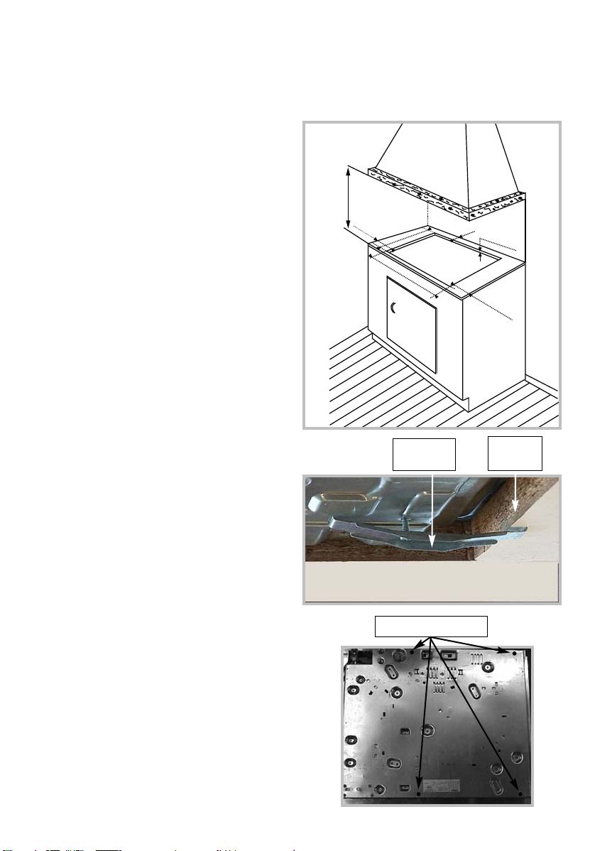
Installing your hob in all simplicity
The hob must be built into the worktop of a support cupboard. This worktop must be at least 3 cm thick and
heat-resistant or else coated with a
heat resistant material.
A side-clearance of at least 30 cm
should be left to the right and left of
the hob. A tall cupboard or partition
too close to the hob would hinder free
movement of kitchen utensils.
If a horizontal partition is put under
the hob, it must be placed between 10
and 15 cm from the bottom of the
worktop. In any case, do not keep any
sprays or pressurized containers in the
compartment which could be just under the hob.
Place the hob unit into the opening in
the worktop by carefully pulling it towards you.
Put the burners, caps and pan grates
back into position.
Connect the hob power cable to your
kitchen electricity supply (See "Elec-
trical Connections" for your hob).
If you want, you can fix the hob in position on its four corners, using the
four lugs and screws provided (See
diagram).
Only use the holes provided.
Stop screwing when the lug
starts to bend.
Do not use a power screwdriver.
Fitting recommendations (cont'd)
Mounting
pad.
Fixing holes
Worktop
37
70 cm mini
30 cm
m
5,3 cm mini
ini
49 cm
56 cm
3 cm mini
30 cm
m
ini
Page 8
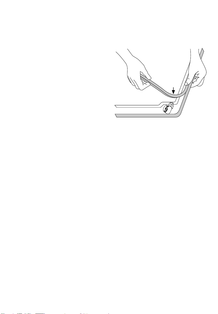
Installing your hob in all simplicity
To make sure that nothing can get
between the frame and the worktop,
stick the foam seal around the out-
side of the hob.
Affix the joint provided in the folder
before installing the hob :
1- Remove the pan support grates,
the burner caps and heads after checking their position.
2- Turn the hob over and place it
gently over the opening in the worktop paying attention not to damage
the control knobs, thermocouples and
lighters.
3- Stick the foam seal delivered with
the appliance around the outside of
the hob. This seal prevents anything
getting between the glass and the
worktop.
4- Put the burners, caps and pan
grates back into position.
38
Fitting recommendations (cont'd)
Seal
Page 9
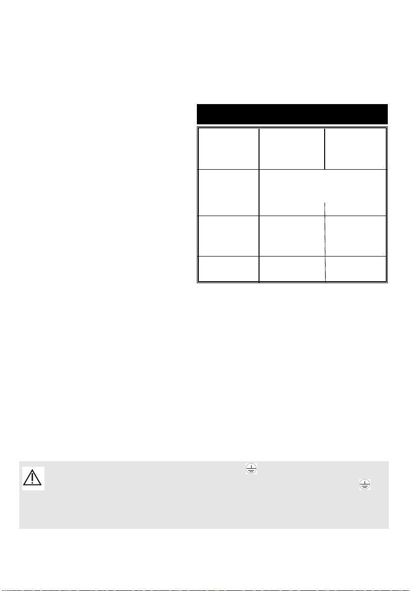
39
Installing your hob in all simplicity
Hobs are delivered with a threeconductor (2 phase + earth) H05VVF T105, ou H05V2V2F - T90 1mm section cable, and must be connected to
a 230V single phase mains supply by
the intermediary of a two phase + CEI
60083 standardised earth plug, or a
single pole cut-off device with a
contact opening by at least 3mm.
Electrical connections
The protective conductor is connected to the earth connection on the hob
and therefore must also be connected to an external earth connection .
If this cable is damaged, have it replaced by your After-Sales Service as special tooling is required to connect it correctly.
● Mixed and all-gas hobs
Cable H05VVF - T105
or H05V2V2F - T90
Cross section of
conductors in
mm
2
Fuse
230 V~ - 50 Hz
All-gas and
mixed
(3+1)
1
10 A
2+ 2 radiants
1,5
16 A
CROSS SECTION OF THE CABLE TO USE
3 conductors of which 1 is to be
earthed
Page 10

Installing your hob in all simplicity
If the hob is to be installed above an
oven or if other nearby heating
appliances risk heating and damaging
the gas hose then it is essential that
a rigid pipe be installed instead.
If a flexible hose is used (in the case
of butane gas) then it must not be
installed in a place where it may be in
contact with a moving part of the kitchen unit or a place likely to get cluttered.
40
Gas connections
● Preliminary remarks
fig.A fig.B
Reinforced, braided,
flexible gas hose with
threaded connectors
Flexible gas hose with
threaded connectors
Access to the whole length of the connection hose must be possible and the gas
hose must be replaced before its use before date (indicated on the hose).
Whatever means of connections is chosen, make sure that it is gas sound after installation by using soapy-water.
Page 11

41
Installing your hob in all simplicity
Gas connections (Cont'd)
● Possible connections
NATURAL GAS
Meter
TOWN GAS (NATURAL GAS)OR AIR-PRO-
PANE / AIR-BUTANE.
One of the 3 following connections
must be used:
-
connection with a rigid pipe
(gas
standard G1/2).
The connection should be made at the end
of the elbow seal on the appliance,
or -
connection with a reinforced,
braided, flexible gas hose with
threaded connectors
(fig. A on the
preceding page).
You may also use a "Gazinox" type,
stainless steel flexible tube available
from your local distributor,
or
- connection with a flexible gas
hose with threaded connectors
(fig. B on the preceding page).
These hoses must not exceed 2
metres in length and their entire
length must be accessible.
Page 12

Installing your hob in all simplicity
42
Gas connections (Cont'd)
● Possible connections
B
OTTLED OR TANKED GAS (BUTANE/PRO-
PANE
).
For the user's safety, we advise the
connection to be made with a rigid pipe if this is possible, or with a reinforced, braided, flexible gas hose (maximum length 2 metres) (fig. A).
For an existing installation, where
it is not possible to fit a reinforced,
braided, flexible gas hose, the connection can be made with a flexible gas
hose (maximum length 2 metres), wi-
th two jubilee clips: one on the
connector (fig. B), and the other on
the pressure regulator, and a gas
proof washer should be fitted between
the connector and the elbow seal on
the hob.
You will find the sealing washer and
the adaptor in the wallet delivered with the unit.
BUTANE/PROPANE
Pressure regulator compulsory
propane
butanene
propane
Temperatures above 30°C would cause overheating of the gas hose. To
avoid this, check that there are no heat-producing devices nearby.
Screw on the connector with a torque not exceeding 2.5 m/daN (m/kgF).
Gas proof
washer
(supplied)
Jubilee clip
(supplied)
Jubilee clip
(not supplied)
fig. A
fig. B
Reinforced,
braided, flexible
gas hose with
threaded
connectors
Flexible hose
connection
propane
Page 13

43
Installing your hob in all simplicity
Changing the type of gas supply
● Preliminary remarks
Your hob is delivered regulated
for natural gas.
The injectors for adapting the hob for use
with butane or propane are in the wallet
containing the instructions, together with
the adaptor and the sealing washer. Please
see the corresponding paragraph on
"Gas Connections".
You can obtain an adapter sachet
from your After-sales Service.
Every time you change your gas
supply, mark the square on the label
in the wallet that corresponds to the
new type of gas (See "Gas Rating" in
this chapter).
Page 14

Installing your hob in all simplicity
44
Changing the type of gas supply (cont'd)
Spanner
Spanner
Line
Line
Fig. 3
Fig. 2
Cover
Head
Dish
Grill
Glass top
Fig. 1
● Changing from natural gas to
butane/propane gas
When carrying out this operation, you
should successively:
➊
Adapt the gas connection
❷
Change the injectors
❸
Adjust the retarder on the taps
➊
ADAPT THE HOB CONNECTION to the
new gas adjustment. Refer to the paragraph “Gas connections”.
❷
CHANGE THE INJECTORS in the following way:
•
Remove the supports, and all the
burner caps and heads.
•
Using the spanner supplied, unscrew the injectors at the bottom of each dish and remove them (fig 1).
•
Replace these with the injectors
supplied in the wallet, in accordance with the gas rating table at the
end of the chapter; to do this:
➪ Screw in the injectors by hand
until they are tight.
➪ Put the spanner well onto the injector.
➪ With a pencil draw a line on the
hearth plate as indicated (fig. 2).
➪ Turn the spanner clockwise until the line appears on the other
side (fig. 3). Warning! Do not
go beyond this limit as you
are liable to cause damage.
Page 15

45
Installing your hob in all simplicity
Changing the type of gas supply (cont'd)
● Changing from natural gas to
butane/propane gas (cont'd).
Adjustment
screw
Tap axis
Fig. 4
❸
ADJUST THE RETARDER ON THE TAPS
located under the knobs. Proceed as
follows:
•
Work on one tap at a time.
•
Remove the control knobs by pul-
ling them upwards.
•
Using a small screwdriver screw
fully the brass, adjustment screw
(yellow) (Fig. 4) clockwise
.
•
Check the position of the knobs before putting them back in place. Make
sure the knobs are pushed down as
far as possible.
•
Put all the burners, covers and grills
back in position.
Page 16

46
Installing your hob in all simplicity
Changing the type of gas supply (cont'd)
When carrying out this operation, you
should successively:
➊
Adapt the gas connection
❷
Change the injectors
❸
Adjust the retarder on the taps
➊
ADAPT THE HOB CONNECTION to the
new gas adjustment. Refer to the paragraph “Gas connections”.
❷
CHANGE THE INJECTORS in the following way:
•
Remove the supports, and all the
burner caps and heads.
•
Using the spanner supplied, unscrew the injectors at the bottom of each dish and remove them (fig 1).
•
Replace these with the injectors
supplied in the wallet, in accordance with the gas rating table at the
end of the chapter; to do this:
➪ Screw in the injectors by hand
until they are tight.
➪ Put the spanner well onto the injector.
➪ With a pencil draw a line on the
hearth plate as indicated (fig. 2).
➪ Turn the spanner clockwise until the line appears on the other
side (fig. 3). Warning! Do not
go beyond this limit as you
are liable to cause damage.
•
Put all the burners, covers and grills
back in position.
● Changing from butane / propane gas
to natural gas or air-propane / airbutane.
Spanner
Spanner
Line
Line
Fig. 3
Fig. 2
Cover
Head
Dish
Grill
Glass top
Fig. 1
Page 17

47
Installing your hob in all simplicity
Changing the type of gas supply (cont'd)
● Changing from butane / propane gas
to natural gas or air-propane / airbutane (cont'd).
Adjustment
screw
Tap axis
Fig. 4
❸
ADJUST THE RETARDER ON THE TAPS
located under the knobs. Proceed as
follows:
•
Work on one burner at a time.
- Light up the burner at maximum
heat.
- Remove the corresponding control
knob
- Using the small screwdriver, unscrew
the brass, adjustment screw (yellow)
turning it round twice, anti-clockwise (Fig. 4).
- Put the control knob back in place
and turn to minimum flame.
- Remove the knob again then turn
the adjustment screw clockwise as
low as possible without extinguishing
the flames.
- Put back the sealing ring and control
knob then turn it several times from
maximum position to minimum position : the flame must not be extin-
guished. Otherwise, re-adjust it by
slightly screwing or unscrewing the
adjustment screw so that a stable flame is obtained when the knob is turned from maximum to minimum position.
Page 18

Appliance designed for installation: Butane Propane Natural Natural Air-
FR ....................................Cat : III1C2E+3+ gas gas propane
ES - GB - PT......................Cat : II2H3+ Air-
butane
G30 G31 G20 G25 G130
Hourly input -see below: 28-30 mbar 37 mbar 20 mbar 25 mbar 8 mbar
at 15°C at 1,013 mbar
Double-crown burner
Indicator marked on injector 95 95 147 147 360
Nominal heat rating (kW) 3,60 3,60 4,00 4,00 3,60
Low heat rating (kW) 1,450 1,550 1,300
Hourly output (g/h) 262 257
Hourly output (l/h) 381 443 503
Fast burner
Indicator marked on injector 78 78 121 121 210
Nominal heat rating (kW) 2,25 2,25 2,30 2,30 2,40
Low heat rating (kW) 0,830 0,870 0,650
Hourly output (g/h) 164 161
Hourly output (l/h) 219 255 336
Extra fast burner
Indicator marked on injector 88 88 137 137 298
Nominal heat rating (kW) 3,10 3,10 3,10 3,10 3,10
Low heat rating (kW) 0,830 0,870 0,780
Hourly output (g/h) 225 221
Hourly output (l/h) 295 343 434
Semi-fast burner
Indicator marked on injector 62 62 94 94 165
Nominal heat rating (kW) 1,45 1,45 1,50 1,50 1,50
Low heat rating (kW) 0,620 0,615 0,400
Hourly output (g/h) 105 104
Hourly output (l/h) 143 166 210
Auxiliary burner
Indicator marked on injector 45 45 63 63 122
Nominal heat rating (kW) 0,750 0,750 0,850 0,850 0,850
Low heat rating (kW) 0,300 0,350 0,350
Hourly output (g/h) 55 54
Hourly output (l/h) 81 94 119
65 cm model with 4 gas burners
Total heat nominal rating (kW) 7,55 7,55 7,75 7,75 7,85
Maximum output (g/h) 549 540
(l/h) 738 858 1099
65 cm model with 4 gas rings, and double crown burner
Total heat nominal rating (kW) 8,05 8,05 8,65 8,65 8,35
Maximum output (g/h) 647 576
(l/h) 824 958 1168
30 cm model with 2 gas burners
Total heat nominal rating (kW) 4,55 4,55 4,60 4,60 4,60
Maximum output (g/h) 330 325
(l/h) 438 509 644
65 cm model with 3 gas burners + 1 electric ring
Total heat nominal rating (kW) 6,10 6,10 6,25 6,25 6,35
Maximum output (g/h) 444 436
(l/h) 595 692 889
65 cm model with 2 gas burners
+ 1 radiant ring 1200 W + 1 halogen ring 1800 W
Total heat nominal rating (kW) 4,55 4,55 4,60 4,60 4,60
Maximum output (g/h) 330 325
(l/h) 438 509 644
48
Installing your hob in all simplicity
Changing the type of gas supply (cont'd)
● Gaz rating
PT FR-GB FR-GB
FR FR
FR-GB-ES ES-PT ES-PT
Page 19

49
Installing your hob in all simplicity
Changing the type of gas supply (cont'd)
● Gaz rating
94 121
137 63
62 78
88 45
165 210
298 122
65 cm model with 4 gas burners
65 cm model with 4 gas rings, and double crown burner
This table shows the position of the injectors on your hob depending on the type of gas you use. The number is marked
on each injector.
Butane/Propane
gas
Air- Butane/Air-
Propane
MARK ON THE INJECTORS
94 121
147 63
62 78
95 45
165 210
360 122
Butane/Propan
e gas
Air- Butane/Air-
Propane
137
94
88
62
298
165
30 cm model with 2 gas burners
Butane/Propane
gas
Air- Butane/Air-
Propane
94 137
62 88
65 cm model with 2 gas burners
+ 1 radiant ring 1200 W
+ 1 halogen ring 1800 W
Butane/Propa
ne gas
165 298
Air- Butane/Air-
Propane
121
137 63
78
88 45
210
298 122
65 cm model with 3 gas burners
+ 1 electric ring 1500 W
Butane/Propan
e gas
Air- Butane/Air-
Propane
Natural gas
Natural gas
Natural gas
Natural gas
Natural gas
Page 20

To set off the safety system, keep
the knob pressed completely
down for a few seconds after the
flame has lit up.
•
Each burner is controlled by a tap
fitted with a safety device, which
cuts the gas off automatically, if ever
the flame goes out by accident (overflowing, drafts, etc.).
•
The safety device for the burners is
in the form of a
metal rod (a thermocouple) beside to
the flame.
•
Your hob is fitted with an automatic
lighting system
integrated into the control knobs.
•
Should there be an electricity cut,
you can always light a burner using a
match and by pressing down on the
control knob at the same time.
Using your hob in all simplicity
50
•
Choose the ring
you need using the
symbols at the
side of each control
knob; (E.g. back righthand burner).
For lighting a burner:
•
Press down on the
control knob and turn
it anti-clockwise to
maximum flame
height. The lighter for
the burner will spark
as long as you keep
the control knob pressed down.
•
Set the flame
height as required.
The gas tap is closed
when in the
“
¡”
posi-
tion.
How to use your gas burners?
- If ever your flame goes out, relight it as per normal procedure.
Sparker
Burner
holder
Natural gas
injector
Burner cover
Thermocouple
(Gas safety device)
Burner
head
- The flames on the burner are smaller near the grate supports to avoid any damage being
done to the enamel.
- The noise made by certain burners is related to their power and burning gas; this does not
harm the quality of cooking in any way.
Page 21

51
The back right-hand burner is
equipped with a timer (maximum
cooking time 99 minutes). It can,
however, be used independently.
•
Light the back right-hand burner
(see previous page).
•
Set it to the flame height you
require.
•
Press the or touch control
on the timer.
As soon as you put your finger on
one of these two controls, the
timer starts and the cooking time
(in minutes) scrolls down on the
display.
•
Keep your finger on the touch
control until the cooking time you
require is displayed.
When the time is up, the burner will
go out and the timer will blink . An
intermittent beep will sound.
To switch it off, touch any of the timer
controls.
•
Turn the back right-hand burner
control knob back to “¡”.
•
To change the cooking time, you can
press the
or controls.
•
To stop the timer during
cooking, put your finger on the
and touch controls at the
same time, until the timer display
goes out.
The burner will stay alight without
the timer.
Using your hob in all simplicity
How to use the timer (Model with 4 rings and a double crown burner)
When cooking time has over, the gas supply to the burner is cut off
immediately and the burner goes out.
Should there be a power cut when the back right-hand burner is being
used with the timer, the timer cuts itself off when the power supply
comes back on.
Page 22

52
Using your hob in all simplicity
Which pans are best adapted for use on the gas burner ?
•
Recommended pan sizes:
Adjust the flames so that they do not
lick up the side of your pan.
Do not use a pan with a convex
or concave bottom.
Do not leave the gas on beneath an
empty pan.
Do not use pans whose handles may
partially cover control knobs.
Do not use heat regulators, toasters,
steel meat grills or stew-pots that touch the glass-top.
Extra burner
double-crown
20 to 30 cm
Extra burner
Extra fast
18 to 28 cm
Fry-ups
Bringing to the boil
Medium burner
fast
16 to 26 cm
Searing
Semi-fast
12 to 20 cm
Sauces,
Reheating
auxiliary burner
8 to 14 cm
Simmering
RIGHT
WRONG
CONVEX
CONCAVE
Keep all natural air-vents open or have a mechanical ventilation system installed (a mechanically ventilated hood).
- Prolonged, intensive use of the hob may require extra ventilation; by opening a window for example or producing more efficient ventilation by increasing
the power of the existing mechanical ventilation (a minimum air input of
2m3/hour per kW of gas energy is required).
E.g. : for 65 cm hob with 4 gas-rings
Total power : 1.5 + 2.3 + 3.1 + 0.85 = 7.75 kW.
7.75 kW x 2 = 16.5 m3/h per hour minimum flow-rate.
Small burner
Page 23

53
•
For starting cooking, turn the
control knob to the most suitable position for your dish (see cooking table
at the end of the guide). The ring
"power on" light comes on immediately.
•
The residual heat light comes on
under the ceramic top as soon as the
heating zone reaches a high temperature.
•
Finish off your cooking by turning
the control knob back to “¡” just before the end of cooking time; this enables you to take advantage of all
the residual heat.
•
The power level of the rings automatically adjusts (a bright light fading to almost nothing) so that they
maintain an even output temperature to suit your cooking.
Using your hob in all simplicity
•
Residual heat indicator
As long as a cooking zone stays hot,
the light on the display that corresponds to the zone in
question stays lit.
When a cooking zone is switched off, but is still hot, the
residual heat indicator will blink.
How to use the radiant and halogen rings
- Do not put any plastic or aluminium object on the heating surface if it is still hot.
- You will get best results by using a saucepan with a diameter close to the diameter
drawn on the ceramic top.
- Wipe the underneath of your pan before use.
- The ceramic surface is highly resistant, but not completely unbreakable. Avoid bumping it
with saucepans.
- Avoid dragging any saucepans on the hob top as, in the long run, this is liable to wear out
the signs on the ceramic-top.
- Do not touch the heating zone before the residual heat light has
gone out. (Even after a prolonged power cut the temperature of the rings
may still be quite high).
- Do not stare for any length of time at the halogen lamps in the cooking
zones.
- Should a crack appear on the ceramic top, disconnect your appliance
immediately and contact your After-Sales Service.
E.g., position 4
12
10
2
4
8
6
Page 24

54
Using your hob in all simplicity
Which pans work best on a radiant/halogen ring?
•
Use recipients with flat bottoms
that are in perfect contact with the
heating surface:
- Stainless steel with a thick trimetal or
"sandwich" base,
- Aluminium with a thick (smooth) base,
- Enamelled steel.
•
Always use a pan of suitable
size: the diameter of the pan
must be equal to or larger than
the diameter of the radiant ring.
•
The bottom surfaces of recipients in
poor condition may hold or transport substances liable to stain or scratch the hob
surface.
•
Make sure that the underneath of
your pan and the heating surface are
clean and dry.
•
Use a recipient that is big enough
to contain all the foodstuffs to be cooked and choose a setting that is not
liable to cause any overflowing or
splashing.
•
The most suitable recipients give
the most successful results.
•
Use high-walled saucepans for
dishes containing a lot of liquid, so
that nothing is liable to overflow when
boiling.
•
The bottom of the saucepan and
the heating zone should be the same
size.
•
Make sure your saucepan is in the
middle of the heating zone.
•
Heating zones should always be
clean, for dirty heating zones and saucepan bottoms not only deteriorate
the heating surface but also increase
electricity consumption.
•
Use the residual heat as well as
possible by turning off the heat 5 minutes before the end of cooking.
•
Never place any food wrapped in
aluminium or plastic recipients on the
heating zone.
If ever you connect any domestic appliance to a plug near the hob,
make sure that its cable does not come into contact with any hot zones.
Page 25

55
Using your hob in all simplicity
How to use the electric hotplate
•
To heat it up
Turn the knob to the point that corresponds to the cooking you want to do
(See cooking table at the end of the
instruction booklet). The electric
hotplate 'on' light comes on.
The first time you use the electric hotplate, leave it on for 3 minutes at
maximum temperature without using
a pan to harden the surface coating.
Which pans are best adapted for use
on the electric hotplate?
•
Which pans are to be used on the
electric hotplate?
Use pans with flat bottoms that are in
complete contact with the electric hotplate surface:
- Stainless steel with a thick trimetal or
"sandwich" base,
- Aluminium with a thick (smooth) base,
- Enamelled steel.
Always use a pan of suitable
size: the diameter of the pan
must be larger than the diameter
of the electric hotplate.
YES
NO
Finish off your cooking with the knob
turned to (
¡). This lets you take ad-
vantage of the heat that has accumulated in the electric hotplate.
•
Whenever possible use a cover on
your pans to avoid losing any heat by
evaporation.
- Whenever possible use a cover on your pans to avoid losing any heat by
evaporation.
- The electric hotplate stays hot for a certain time after it has been switched off in
the “¡” position.
E.g., position 3
6
5
4
1
2
3
Page 26

56
Looking after
sparkers and
injectors
Looking after
your glass top
- If ever the sparkers
get dirty, clean them
with a stiff nonmetallic brush.
-The gas injectors are
in the centre of each
burner in the form of
a "pot". Make sure not
to block them up partially when cleaning the
hob, as this will considerably reduce the
performance of your gas-rings.
- Small hard-bristled
brush.
- Clean it with hot water, then wipe dry. Use
special ceramic glass cleaning products for
any persistent stains.
- Household sponge
- Special ceramic
glass products
E.g. Cera-Clen
Looking after
the electric
hotplate
- The electric hotplate is protected by a black
surface coating. Therefore, avoid using any
abrasive products. After use, wipe it clean
with an oily cloth.
If ever a electric hotplate starts to rust,
remove the rust with (with emery paper or
similar) and re-coat the electric hotplate with
a high-temperature renovating product to be
found at your local distributor.
- Household sponge
- Special ceramic
glass products
E.g. Cera-Clen
Looking after
the grills and
gas burners
- Use a non-abrasive cream for removing any
persistent stains. Then rinse with clean
water. Dry each burner element carefully
before re-lighting your hob.
- Non-abrasive cream
.
- Household sponge.
HOW TO PROCEED
ACCESSORIES TO
BE USED
Keeping your hob in good condition is easy if you clean it before it is completely
cold. Even so, never clean it when it is in use. Put all the electric and gas control
knobs at zero.
How to look after your hob?
- Should a crack appear on the glass-top, disconnect your appliance immediately and contact your After-Sales Service.
- It is better to wash the parts of your hob by hand rather than in a dishwasher.
- Never use an abrasive sponge for cleaning your hob.
thermocouple
Nut
Injector
Sparker
Page 27

57
You have doubts about whether your hob is working correctly .... ......
this does not
necessarily mean there is a breakdown. Nevertheless, check the following points
If your hob is fitted with a gas safety
device and the flames go out as soon
as you release the control knob.
In the low position the
flames go out or are
too high.
Flames are irregular.
- Avoid any severe drafts in the room.
- Check that the gas you are using corresponds to the injectors that
have been installed (See injector identification in the "Gas Rating"
chapter).
Remember that gas hobs are delivered preset for use with natural gas.
Check the adjustment of the low power screw (See paragraph
"Changing the type of gas supply").
- Check that the burners and injectors are clean and assembled
correctly.
- Check you have enough gas in your gas cylinders.
The knobs get hot during cooking.
Use small pans on the burners next to the control knobs. Large pans
are to be put on the large burners furthest away from the knobs.
Put the pan in place with the burner in the middle. The pan should not
be above the control knobs.
WHAT SHOULD YOU DO?IF YOU REALIZE THAT
Lighting the burners:
There is no sparking when the
control knobs or buttons are pressed
down.
When you only press down one
control knob all the burners spark.
Sparking takes place but the burners
do not light up.
- Check the electrical connections on the hob.
- Check that the sparkers are clean.
- Check that the burners are clean and in position.
- If the hob is fixed to the worktop, make sure that the fixing clamps
have not been twisted.
- Check that the sealing rings have not come out of place.
This is normal. The lighter system is centralised, and all the burners
spark at the same time.
- Check that the gas inlet pipe has not been squashed.
- Check that the gas inlet pipe tube is less than 2m long.
- Check that the main gas tap is open.
- If you use gas tanks or cylinders check that they are not empty.
- If you have just installed your hob or changed a gas cylinder, keep
the control knob wide open for a few seconds so that the gas can get
through.
- Make sure the injector is not blocked up. if this is the case, clear it
with a safety pin.
- Light up your gas burner before putting a pan on it.
- Push the control knob down completely and keep it under pressure
for a few seconds after the burner has lit.
- Check that the burner parts are in place.
- Check that the sealing rings under the control knobs have not come
out of place.
- Avoid any severe drafts in the room.
- Light the burner before putting your pan on it.
Minor troubleshooting
Page 28

58
Gas-cooking guide
DISHES TIME EXTRA- FAST SEMI- DOUBLE- AUXILIARY
FAST FAST CROWN
SOUPS Broths 8-10 minutes XX
Thick soups X
FISH Court-bouillon 8-10 minutes XX
Grilled 8-10 minutes X
SAUCES Hollandaise, bearnaise XX
Bechamel, aurore 10 minutes XX
VEGETABLES Endives, Spinach XX
Peas In Sauce 25-30 minutes XX
Provence Tomatoes 15-20 minutes XX
Fried Potatoes XX
Pasta XX
MEAT Steack XX
Blanquette, Osso-bucco 90 minutes X
Fried Escalope 10-12 minutes X
Tournedos (cast iron grill pan) 10 minutes XX
FRYING Chips XX
Fritters XX
DESERTS Rice Pudding 25 minutes X
Stewed Fruits XX
Pancakes 3-4 minutes XX
Chocolat 3-4 minutes X
Custard 10 minutes X
Coffee (Small Coffee-Pot) X
Page 29

SOUPS Broths 6
Thick soups 5
FISH Court-bouillon 7
Frozen 6
SAUCES Thick made with flour 4-3
Made with butter and eggs 3
(Bearnaise, Hollandaise)
VEGETABLES Endives, Spinach 76
Peas In Sauce, 53
Boiled Potatoes 65
Boiled Potatoes 76
Saute Potatoes 76
Defrosting vegetables 4
MEAT Thinly sliced meat 12
Frying steaks 11
Grilling 12
FRYING Frozen chips 12
Fresh chips 12
MISCELLANEOUS
Pressure cooker 12 6 (once it hisses)
Stewed fruit 4
Pancakes 11 10
Custard 3
Melting chocolate 1
Jam 5
Milk 6
Fried eggs 9
Pasta 12 6
Baby food in jars 4
(bain marie)
Stews 5
Rice pudding 3
keeping warm 2-1
SIMMERING KEEPING
DISHES VERY HOT HOT MEDIUM LOW REHEATING WARM
12-11 10-9 8-7-6 5 4-3 2-1
59
Cooking guide for radiant/halogen rings
To get the best possible results, follow the examples in the charts and remember that maximum
power (12 - 11) is only to be used for rapid frying and boiling.
Page 30

60
VERY HOT HOT MEDIUM SIMMERING KEEPING
DISHES WARM
66 5 3-4 2 1
SOUPS Broths 65
Thick soups 3
FISH Court-bouillon 65
Frozen 65
SAUCES Thick made 3-4
with butter 2
VEGETABLES Endives, Spinach 5
Peas In Sauce 3-4
Boiled Potatoes 5
Fried Potatoes 5
Saute Potatoes 3-4
MEAT Steacks 6
Grilling 6
FRYING Chips 6
MISCELLANEOUS Sewed 2
Pancakes 6
Custard 2
Melting chocolate 1
Jam 3-4
Milk 5
Pasta 65
Rice pudding 2
keeping warm 1
Cooking guide for electrical hobs
 Loading...