

Page 1
D MONTAGE- UND GEBRAUCHSANWEISUNG
GB INSTRUCTION ON MOUNTING AND USE
F PRESCRIPTIONS DE MONTAGE ET MODE D’EMPLOI
NL MONTAGEVOORSCHRIFTEN EN GEBRUIKSAANWIIZING
I ISTRUZIONI DI MONTAGGIO E D’USO
E MONTAJE Y MODO DE EMPLEO
P INSTRUÇÕES PARA MONTAGEM E UTILIZAÇÃO
DK MONTERINGS- OG BETJENINGSVEJLEDNING
Page 2
6
7
1
5
3
2
4
1
f
j
g
g
i
2
c
b
4
a
g
g
h
3
Page 3

3
4
273
273
244
214
14,5
190
4
4
4
4
4
6
6
7
5
6
9
7
7
7
8
8
7
2a
S
2a
2b
10
2a
10
10
10
2b
2a
B
12
5
11
11
Page 4

G
14
F
15
15
15
15
13F
H
16
13A
16
15
15
15
15
6
Page 5

18
18
18
18
18
18
18
18
17
18
18
M
X
19
20
X
7
20
19
Page 6

8
INSTRUCTION ON MOUNTING AND USE GB
Consult the designs in the front pages referenced in the text
by alphabet letters. Closely follow the instructions set
out in this manual. All responsibility, for any eventual
inconveniences, damages or fires caused by not complying
with the instructions in this manual, is declined.
The cooker hood must be placed at a minimum distance of
50 cm from the cooking plane for electric cookers and 75cm
for gas or mixed cookers.
Do not tile, grout or silicone this appliance to the wall. Surface
mounting only.
The hood is equipped with a top air outlet B for discharge
of fumes to the outside (Ducting version – exhaust pipe
and pipe fixing clamps not provided).
Should it not be possible to discharge cooking fumes and
vapour to the outside, the hood can be used in the filter
version, fitting an activated carbon filter and the deflector F
on the support (bracket) G, fumes and vapours are recycled
through the top grille H by means of an exhaust pipe
connected to the top air outlet B and the connection ring
mounted on the deflector F (exhaust pipe and pipe fixing
clamps not provided).
The models with no suction motor only operate in ducting
mode, and must be connected to an external suction device
(not supplied).
Expansion wall plugs are provided to secure the hood to
most types of walls/ceilings. However, a qualified technician
must verify suitability of the materials in accordance with the
type of wall/ceiling. The wall/ceiling must be strong enough
to take the weight of the hood.
Do not tile, grout or silicone this appliance to the wall.
Surface mounting only.
Installation - Fig. 5-6-7
Preliminary information for installing the hood
Assembling the deflector (Fig. 6 - 3 parts – only for
filter version):
The three parts should be fixed with 2 screws, the deflector
extension is adjustable and should correspond to the width
of the chimney flue support, to which it is then fixed.
During electrical connection ensure the power supply is
disconnected at the domestic main switch.
1 . Adjust extension of the hood support structure, as the final
height of the hood depends on this, and remember that
with installation completed the hood must be at least 50
cm above the cook-top for electric cookers and 75 cm
for gas or mixed cookers.
2. a. Fix the two sections of the structure using 8 screws.
b. If the hood is provided with extensions longer than the
minimum, fit the reinforcement bracket S to the frame,
using 4 screws.
3. Place the ceiling hole diagram directly above the cooktop (the center of the diagram must match the center of
the cook-top and the edges must be parallel to the sides
of the cook-top – the side of the diagram with the wording
FRONT corresponds to the control panel side). Prepare
the electrical connection.
4. Drill as shown (6 holes for 6 wall plugs – 4 plugs for
fixture), screw the outer screws leaving a space of about
1 cm. between the screw head and the ceiling.
5. Fit an exhaust pipe inside the truss and connect it to the
motor compartment connection ring (exhaust pipe and
fixing brackets are not supplied).
6. Hook the frame onto the 4 screws (see step 4).
CAUTION! The side of the truss with connection box
corresponds to the side of the control panel with hood
assembled.
7. Tighten the 4 screws.
8. Insert and tighten another 2 screws in the remaining free
holes for secure fixing.
9. Carry out the electrical connection to the mains power
supply, only turn on the power supply upon completion
of assembly.
10. Hook the hood onto the truss, ensuring it fits properly –
to hook the hood onto the truss partially tighten 4 screws
(see also step 12).
11. Secure the hood to the truss using two screws; this will
also help center the two sections.
12.Tighten the 4 screws securing the truss to the hood.
13.For extractor versions (13A), connect the other end of
the exhaust pipe to the flue.
For filter versions (13F), fit deflector F to the truss and
secure it to the bracket supplied using 4 screws, then
connect the exhaust pipe to the connection ring located
on the deflector.
14. Fit the nuts with fixing hooks supplied
bottom sections of the flues at the rectangular slots. A total
of 10 nuts must be fitted.
15. Join the two top sections of the flue to cover the truss so
that one of the slots on the sections is situated on the same
side of the control panel and the other on the opposite side.
Screw the two sections together with 4 screws (2 each
side- see the plan diagram for joining the two sections).
16. Fix the top flue assembly to the truss, near the ceiling,
with two screws (one each side).
17.Carry out electrical connection of control panel and
bulbs.
Warning! Make connections taking care to insert
the connectors in the right way.
18. Join the two bottom sections of the flue covering the truss
using 6 screws (3 each side, see the plan diagram for
joining the two sections).
19. Insert the bottom section of the flue in its seat so that it
completely covers the motor compartment and electrical
connection box, then ensure it from inside the hood using
two screws.
20. Apply the 2 tabs (supplied) to cover the fixing points of
the bottom flue (CAUTION! THE BOTTOM FLUE TABS
ARE THE NARROWER AND SHALLOWER ONES).
The wider and deeper tabs are those used for the top flue,
and must be cut to size.
21. Turn the mains power on again at the central electrical
panel and check for correct hood operation.
Electrical connection
The electrical tension must correspond to the tension noted
on the label placed inside the cooker hood. Connect the
electrical plug, where provided, to the an easily accessible
outlet in conformity with local standards in force.
Where an electrical plug is not provided (for direct connection
to electrical network) place a standards approved bipolar
switch with an aperture distance of not less than 3mm
(accessible) from the contacts.
inside the top and
Page 7

GB
INSTRUCTION ON MOUNTING AND USE
9
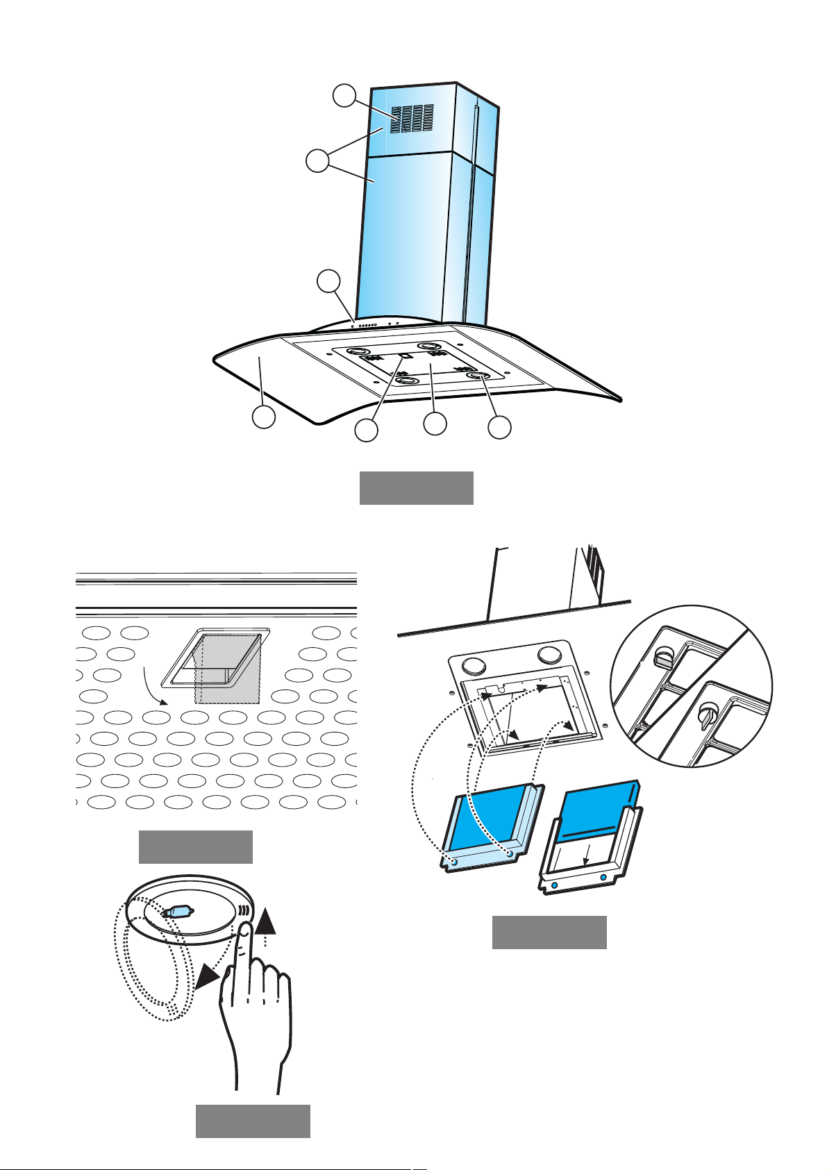
Description of the hood - Fig. 1
1 Control panel
2 Grease filter
3 Grease filter release handle
4 Halogen lamp
5 Vapour screen
6 Telescopic chimney
7 Air outlet (used for filter version only)
Operation –
Model with button panel
Description of control panel and hood operation
ABCD
A. on/off light switch
B. on/off aspiration switch and minimum power selection
B+C. medium power selection aspiration switch
B+D. maximum power selection aspiration switch
Operation –
All cooker hood versions
Use the high suction speed in cases of concentrated kitchen
vapours. It is recommended that the cooker hood suction
is switched on for 5 minutes prior to cooking and to leave
in operation during cooking and for another 15 minutes
approximately after terminating cooking.
Maintenance
Prior to any maintenance operation ensure that the cooker
hood is disconnected from the power supply.
Cleaning
The cooker hood should be cleaned regularly internally and
externally.
For cleaning use a cloth moistened with denatured alcohol
or neutral liquid detergents. Avoid abrasive detergents.
Warning:
Failure to carry out the basic standards of the cleaning of the
cooker hood and replacement of the filters may cause fire
risks.
Therefore we recommend oserving these instructions.
Grease filter
This must be cleaned once a month (and, for the model with
electronic control panel, every time LED 4 starts to flash –
see preceding page) using non aggressive detergents,
either by hand or in the dish-washer, which must be set to
a low temperature and a short cycle.
When washed in a dish-washer, the grease filter may
discolour slightly, but this does not affect its filtering capacity.
To remove the grease filter, pull the spring release handle
(f) - (Fig. 2).
Charcoal filter (filter version only)
It absorbs unpleasant odours caused by cooking.
The charcoal filter can be washed once every two months
(when using the hood 2,5 hours per day, in avarage and,
for the model with electronic control panel, every time LED
5 starts to flash – see preceding page) using hot water and
a suitable detergent, or in a dish-washer at 65°C (if the dishwasher is used, select the full cycle function and leave
dishes out).
Eliminate excess water without damaging the filter, then
remove the mattress located inside the plastic frame and put
it in the oven for 10 minutes at 100° C to dry completely.
Replace the mattress every 3 years and when the cloth is
damaged.
Remove the filter holder frame by turning the knobs (g) 90°
that affix the chimney to the cooker hood (Fig. 3).
Insert the pad (i) of activated carbon into the frame (h) and
fit the whole back into its housing (j).
Replacing lamps - Fig. 4
Access the light compartment
press on the lamp cover and release to open.
Warning!
Prior to touching the light bulbs ensure they are cooled down.
Replace the damaged light bulb.
Only use halogen bulbs of 20W max (G4), making sure you
do not touch them with your hands.
Close the lamp cover (it will snap shut).
If the lights do not work, make sure that the lamps are
fitted properly into their housings before you call for
technical assistance.
Caution
This appliance is designed to be operated by adults. Children
should not be allowed to tamper with the controls or play with
the appliance.
Do not use the cooker hood where the grill is not correctly
fixed! The suctioned air must not be conveyed in the same
channel used for fumes discharged by appliances powered
by other than electricity. The environment must always be
adequately aerated when the cooker hood and other
appliances powered by other than electricity are used at the
same time. Flambé cooking with a cooker hood is
prohibited. The use of a free flame is damaging to the filters
and may cause fire accidents, therefore free flame cooking
must be avoided. Frying of foods must be kept under close
control in order to avoid overheated oil catching fire. Carry
out fumes discharging in accordance with the regulations in
force by local laws for safety and technical restrictions.
 Loading...