

Page 1
DD 3009 GLASS
EFFICIENCY
PROVED BY TIME
Page 2
EQUIPMENT, SYSTEMS, SERVICES
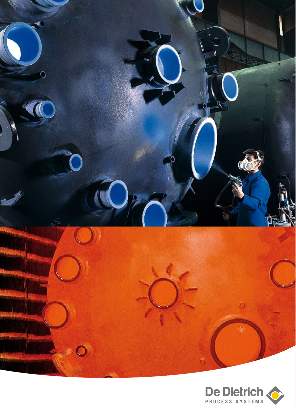
DD 3009 GLASS
Glass-lined steel is mandatory when
service conditions of the process are
particularly difficult. With the DD 3009
glass, De Dietrich® offers an excellent resistance to corrosion, abrasion,
mechanical and thermal shocks.
To increase productivity or to succeed
in new syntheses, the chemical industry continually extends the limits of its
processes: higher temperatures, lower
temperatures, higher pressures, higher
concentrations. This trend is possible
only if at the same time the chemical
and mechanical resistances of the
glass that protects vessels, tanks and
parts follow these requirements.
This is the reason why De Dietrich® has
always invested in research and development of new glass formulas with
greater capabilities. The result of our
ongoing research enabled us to offer
the DD 3009 glass. The formulation
of this multipurpose glass gives the
optimum properties of chemical resistance to acidic and alkaline mediums,
of mechanical resistance to shocks
and abrasion, of easy cleaning and
anti-adhesion.
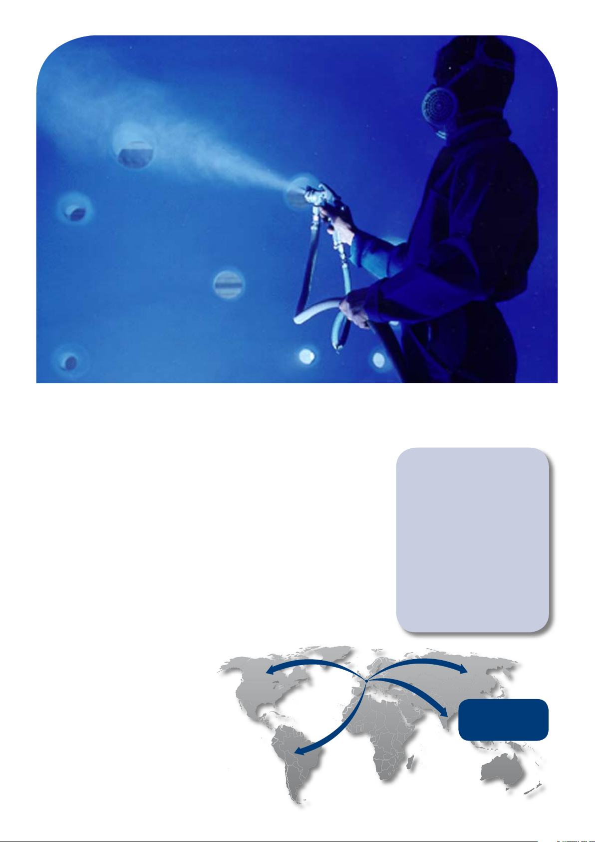
Across the world, all De Dietrich®
plants apply the same quality of glass,
the production of which is centralized
in France. During the preparation
of each batch of DD 3009 glass,
numerous tests assure us a perfect
and reproducible quality, suppressing
any risk of production defect. Thanks
to su ch rig orous contr ol, we can
confidently state that, at De Dietrich®,
“Quality” is an everyday occurrence.
Monitoring R&D and production of
our own glass in for De Dietrich® an
emblem of quality, of competence, of
independence.
ONE GLASS
WITH OPTIMUM QUALITY
DD 3009, ONE GLASS WITH OPTIMUM
QUALITY FOR ALL PRODUCTS ALL
OVER THE WORLD:
• HIGHLY CORROSIVE PROCESSES
• MULTIPURPOSE MATERIAL /
VARIETY OF USES
• ADAPTED TO
MENTS, CLEANING, CLEANLINESS,
STERILIZATION
• IMPERVIOUS: NO CATALYTIC
EFFECT, NO CONTAMINATION
• ANTI-ADHESIVE: POLYMERIZATION
PROCESSES
cGMP REQUIRE-
ONE GLASS WITH
OPTIMUM QUALITY ALL
OVER THE WORLD
Page 3
CHEMICAL PROPERTIES
190
180
170
160
150
140
130
120
110
10 40 60
°C
20 30 50 70
HNO
3
Weight %
0.2 mm/year
0.1 mm/year
210
200
190
180
170
160
150
140
130
10 40 60
0.2 mm/year
°C
20 30 50 70 80
H2SO
4
Weight %
0.1 mm/year
180
170
160
150
140
130
120
110
10 20 30
Weight %
°C
HCI
0.2 mm/year
0.1 mm/year
190
180
170
160
150
140
130
120
110
10 40 60
Weight %
°C
20 30 50 70 80
H3PO
4
0.2 mm/year
0.1 mm/year
230
220
210
200
190
180
170
160
140
10 40 60
0.2 mm/year
°C
20 30 50 70 80
CH3COOH
90 100
0.1 mm/year
Weight %
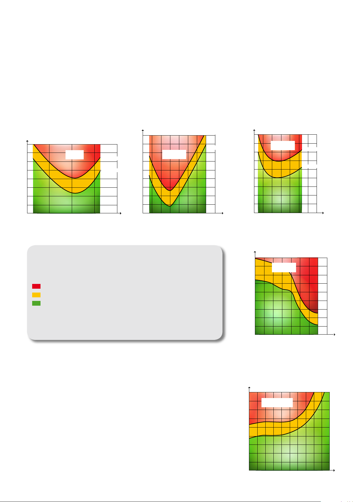
RESISTANCE TO ACIDS
Generally, DD 3009 glass has a high
degree of resistance to acids whatever
their concentration, up to relatively
high temperatures. For most of the
inorganic acids, the resistance of the
glass passes through a minimum for a
concentration of 20-30% weight, then
increases with the acid concentration.
For example, the 0.1 mm/year rate is
found at 128°C in H2SO4 30% and at
180°C in H2SO4 60%. Exceptionally,
in the case of phosphoric acid, the
speed of attack increases with the
concentration: 0.1 mm/year at 163°C
for 10% concentration and at 112°C for
70% concentration.
Hy dro flu ori c ac id c omp let ely and
quickly dissolves the glass whatever
the temperature is. Its concentration in
the product must not exceed 0.002%
(20 ppm).
RESISTANCE
TO ORGANIC SUBSTANCES
Chemical attack is very low in organic
substances. If water is given off during
the reaction, the rate of attack will
depend on the amount of water in the
solution. In the case of 0.1N sodium
hydroxide in anhydrous alcohol at
ISOCORROSION CURVES
OUR ISOC ORROSION CURVES ARE ESTABLISHED FOR MOST CURRENT PRODUCTS. THEY
SHO W AS A FUNCTION OF PRODUCT CONCENTRATION THE TEMPERATURES AT WHICH
THE WEIG HT LOSSES CORRESPOND TO 0.1 AND 0.2 MM/YEAR.
TH E USE OF GLASS IS NOT ADVISABLE
CA RE MU ST BE TAKEN OF THE ADVANCE OF THE CORROSION
GL ASS C AN BE USED WITHOUT PROBLEMS
ALL THE TEST HAVE B EEN PERFORMED IN TANTALUM LINED REACTORS AND USING A
RATIO VOLUME OF P RODUC T / SURFACE OF ENAMEL (V/S) > 20 TO AVOID THE INHIBI
TIO N OF THE ATTACK BY D ISSOLVED SILIC A.
80°C, the rate of attack is virtually nil.
In methanol, there has to be more than
10% water before the loss of weight can
be measured, whereas in ethanol with
5% water, the weight loss is already half
of what it is in aqueous solution.
-
Page 4

RESISTANCE TO ALKALIS
110
100
90
80
70
60
50
40
10
-2
10
-1
1 10 30
Weight %
0.2 mm/year
0.1 mm/year
°C
Na2CO
3
120
110
100
90
80
70
60
50
10
-3
10
-2
10-10,4 4
0.2 mm/year
0.1 mm/year
°C
0,04 1 10 30 50
11 12 13 14 pH
NaOH
Weight %
150
140
130
120
110
100
90
80
10
-2
0,4 4
0.2 mm/year
0.1 mm/year
°C
0,04 1 10 3010
-1
NH
3
Weight %
100
80
60
40
20
20
Speed of attack (%)
HCI 20 % at 160°C
Micronised silica
(Levilite)
40 60 80 100
ppm of added silica
%
100
80
60
40
20
50
H2SO4 30% at 160 °C
Micronised silica
(Levilite)
100 150 200 250
Speed of attack (%)
ppm of added silica
HCI 20 % at 160°C: 0.5 mm/year
With 100 ppm SiO2: 0.05 mm/year
180
160
140
120
100
10 20 30 40
0.2 mm/year
0.1 mm/year
°C
Weight %
Here the permissible temperature limits
are lower than for acids. At pH = 13
(NaOH 0.1N) this maximum is 70°C.
Therefore, it is important to be cautious
when using hot alkalis. Temperature
must be controlled, as an increase
of 10°C doubles the rate of attack of
the glass. Care must be taken for the
introduction of alkalis into a vessel.
Avoid the flow of alkalis along the warm
vessel wall by using a dip pipe.
RESISTANCE TO WATER
VAPOR
Resistance to water is excellent. The
behavior of glass in neutral solutions
depends on each individual case but in
general is very satisfactory.
CORROSION INHIBITION
Chemical reactions are sometimes so
severe they cause a rapid wear on the
enamel surface. The use of additives
NaOH 1N 80 °C 0.18 mm/year 0.09 mm/year
Buffer pH= 1 ; 100°C + HF 430 ppm 1.5 mm/year 0.42 mm/year
HCI 20 % vapor 110 °C 0.036 mm/year < 0.005 mm/year
to the reacting substance can inhibit
this corrosion permitting the use of
glass-lined equipment. When using
acids, several tens or several hundreds
ppm of silica protect th e enamel
and considerably reduce the rate of
corrosion during the liquid phase.
The same result can be obtained at
the vapor stage by adding silicon oils.
Generally speaking, the higher the
temperature, the greater the quantity
of silica required, and more the acid
Pure Product 500 ppm CaCO
is concentrated, the more the amount
of silica can be reduced. In presence
of fluorine, silica also has a favorable
influence. We always recommend a
pre-test as each reaction is different.
An attack inhibitor can be useful in one
case and yet non-effective in another.
3
300 ppm SiO
2
Silicon Oil 2 ml/l
Page 5

MECHANICAL PROPERTIES
Ena mel is a gl ass wit h its qualitie s but also its main weaknesses
whi ch are brittleness and low tensil e strength. Since the res istan ce of
gla ss to compression is well above
its tensi le strength , one of the solutio ns to improve the mec hanic al
res istan ce is to put the glazed layer
und er compressive pre-stress. This
is achieved during controlled cooling
after each firing. During mechanical work
(de forma tion, mechanical or thermal
sho ck) the compressive stress must
fir st be offset by an equivalent tensil e befo re the glass could be put
und er da ngerous tensile stress.
ABRASION
The abrasion test (DIN 51152) is far
from the actual working conditions of
a glass-lined reactor where the effects
of the chemical attack enhance those
of abrasion. Nevertheless, it allows a
comparison between glasses, showing
DD 3009 advantageously. Statistically,
it has been shown that in practice the
cases of destruction by abrasion are
negligible. However, should any doubt
arise when an abrasive substance is
being used, only a comparative test
performed with that product could lead
to a conclusion.
MECHANICAL SHOCK
The different experimental arrangements used for measuring the mechanical shock resistance produce results
which cannot be compared to each
other. Therefore, there is little use
trying to give intrinsic values of the
mechanical shock resistance. The only
way to compare different glasses is to
use the same method and the same
criteria.
In our method, a 1 kg mass equipped
with a 15 mm ball is dropped onto
a glass-lined plate (glass thickness:
1.5 mm). This plate is locked onto
a magnetic base, thereby making
it thicker and increasing the shock
ef fici ency ( n o ener gy abs orpt ion
through steel vibrations). The plate is
electrically grounded, and the electric
current going through an electrolyte
deposited at the shock location is used
as assessment criteria. When tested to
this procedure, which is close to the
real service conditions, the mechanical
shock resistance of the DD 3009 glass
is about 80 % greater than that of the
former glass.
UNITS DD 3009 GLASS
HCI – Vapor – DIN 51157 - ISO 2743 mm/year 0.036
HCI – 20 % 140 °C – V/S = 20 mm/year 0.2
NaOH 1N 80 °C – DIN 51158 – ISO 2745 mm/year 0.19
NaOH 1N 80 °C – V/S = 20 mm/year 0.35
NaOH 0.1 N 80 °C – V/S = 20 mm/year 0.18
H2O – Vapor – DIN 51165 – ISO 2744 mm/year 0.017
Thermal shocks – Statiflux surface cracks °C 220
Abrasion – DIN 51152 mg/cm2/h 2.35
Mechanical shocks Improvement against former glass: 80 %
Page 6

THERMAL PROPERTIES
The large majority of equipment that we
manufacture is designed with a system
that enables the heating and cooling of
their contents. As heat transfers may
cause serious damage to the enamelled
coating, the user should respect the
limits described in this chapter, which
take account both of the data in the
EN 15159 standard (parts 1, 2 and 3)
and our experience as a constructor of
glass-lined equipment.
A DISTINCTION SHOULD BE
MADE BETWEEN :
• The “thermal shock” proper, which
is characterised by an abrupt change
in temperature applied either to the
surface of the enamel (introduction of
a product into the appliance: reagent,
cleaning water), or to the steel (such as
jacket nozzle location when introducing
for example super-heated steam).
• The «thermal stresses», which are
mechanical stresses related to temperature gradients which appear temporarily in the steel during phases of
temperature changes. These are related
to the design of equipment and may
generate stresses in the enamel, which
may cause its rupture, and/or result in
fissuring of the passivation layer in coils
and foster the development of corrosion
under stresses, which may lead to the
appearance of transverse cracks.
are different from standard (very high
temperature, very low temperature,
high pressure, …), or because of a
particular material or design such as
The maximum ΔT values given in
these tables MUST be respected. They
are limit values which must not be
exceeded.
glass-lined stainless steel equipment,
columns without compensator, dissymmetrical appliances (lyre and lateral
nozzle), non-standard thicknesses,
non-standard lengths, jacketed piping,
etc...
NOTE
Instructions devoted entirely to the
thermal properties of the enamel are
attached to the Maintenance Manual of
our equipment to enable their installaThe following table is provided to
enable you to validate your operating
conditions and obviate the creation of
tion and use in complete safety, as far
as both your operators and the equip-
ment are concerned.
excessive thermal shocks when introducing products into standard equipment or on changes in temperature in
the thermal fluid (Multifluid system).
GENERAL CASE OF STANDARD VESSELS CALCULATED FROM -25°C
TO +200°C EN 15159 NORM
WHEN INTRODUCING
THE THERMAL FLUID
IN THE JACKET
A
WHEN LOADING
PRODUCT
INTO THE VESSEL
B
Glass-lined equipment is more or less
sensitive to thermal shocks and thermal
stress es, depend ing on their geo metrical or structural characteristics.
This requires us to make a distinction
between:
• On one hand, standard equipment, in
which the calculation data are –25°C to
+200°C regarding the temperature, and
–1 to 6 bar regarding the pressure.
• On the other hand, specific equipment, either because of their calculation and/or operating conditions, which
Example A
If the product and the glass-lined wall are
at 170°C, the fluid temperature should be
between +30°C and +200°C.
Example B
If the glass-lined wall and the thermal
fluid are at 20°C, products between -25°C
and +165°C may be safely introduced.
Thermal fluid
T° not to exceed
T° T°
mini maxi
-25 120 -25
-25 125 -20
-25 135 -10
-25 145 0
-25 155 10
-25 165 20
-25 170 30
-25 175 40
-25 180 50
-25 185 60
-25 190 70
-25 195 80
-25 200 90
-25 200 100
-25 200 110
-20 200 120
-10 200 130
0 200 140
10 200 150
20 200 160
30 200 170
40 200 180
50 200 190
60 200 200
Product
and wall T°
Product T°
not to exceed
T° T°
mini maxi
-25 125 -25
-25 130 -20
-25 140 -10
-25 150 0
-25 157 10
-25 165 20
-25 175 30
-25 180 40
-25 190 50
-25 200 60
-25 200 70
-25 200 80
-25 200 90
-25 200 100
-25 200 110
-25 200 120
-25 200 130
-5 200 140
5 200 150
20 200 160
30 200 170
45 200 180
60 200 190
75 200 200
Thermal fluid
and wall T°
Page 7

GUARANTEED TRACEABILITY
PRODUCTION OF ENAMEL
Each batch of enamel is comprised of
carefully selected and rigidly controlled raw materials, which are melted
in a rotary furnace at approximately
1.400°C. The melted glass is then
poured into water. This sudden tempering breaks the enamel into grains,
whic h are dri ed and then groun d
and screened. To prevent any contamination, each batch is processed
separately, between each operation, in
closed containers.
GLASSING
A suspension is prepared with enamel
powder and sprayed like a paint on the
surfaces to be glass-lined. After this
coat, called “biscuit”, is air dried, the
parts are charged into a furnace and
fired at temperatures that affect fusion
between glass particles.
After cooling, the result is an impervious, smooth coating of glass. The coat
is then submitted to various controls:
thickness, spark testing and visual
inspection.
Then the item is sprayed with another
coat that will be air dried, fired and
Q.C. tested. These cycles are repeated,
always by the same technician who will
adjust and complete his work, until
obtaining perfect glass lining:
• Thickness between 1 and 2 mm
• Minimum spark test contact
• Good visual quality, smooth without
any color variation
COLOUR
DD 3009 glass is available in two colours
having exactly the same chemical and
mechanical properties:
• Blue (DD 3009)
• White (DD 3009U)
Page 8

DE DIETRICH SAS
Château de Reichshoffen
F 67891 Niederbronn Cedex
Phone +33 3 88 80 26 00
Fax +33 3 88 80 26 95
www.dedietrich.com
SAS. All rights reserved. 001-04/09. © endostock - Fotolia.com
®
BENELUX
De Dietrich Process Systems N.V.
B - Heverlee-Leuven
Phone +32 16 40 5000
Fax +32 16 40 5500
info@benelux.dedietrich.com
BRAZIL
De Dietrich Do Brasil Ltda
São Paulo
Phone +55 11 2703 7380
Fax +55 11 2702 4284
brasil@dedietrich.com.br
CHINA
De Dietrich Process Systems Co. Ltd
Wuxi
Phone +86 510 8855 7500
Fax +86 510 8855 9618
info@dedietrichchina.com
FRANCE
De Dietrich S.A.S.
Zinswiller
Phone +33 3 88 53 23 00
Fax +33 3 88 53 23 99
sales@dedietrich.com
De Dietrich S.A.S.
Evry
Phone +33 1 69 47 04 00
Fax +33 1 69 47 04 10
eivs@dedietrich.com
De Dietrich Process Systems Semur
S.A.S.
Semur-en-Auxois
Phone +33 3 80 97 12 23
Fax +33 3 80 97 07 58
info@rosenmund.com
GERMANY
De Dietrich Process Systems GmbH
Mainz
Phone +49 6131 9704 0
Fax +49 6131 9704 500
mail@qvf.de
GREAT BRITAIN
De Dietrich Process Systems Ltd
Stafford
Phone +44 1785 609 900
Fax +44 1785 609 899
sales@qvf.co.uk
INDIA
De Dietrich Process Systems (India)
Pvt, Ltd
Mumbai
Phone +91 22 28 505 794
Fax +91 22 28 505 731
ddps.india@dedietrich.com
IRELAND
De Dietrich Process Systems Ireland
Ltd
Shannon
Phone +353 61 366924
Fax +353 61 366854
sales@dedietrich.ie
ITALY
De Dietrich Process Systems Srl
San Dona’ Di Piave (VE)
Phone. +39 0421 222 128
Fax +39 0421 224 212
info-it@dedietrich.com
RUSSIA
De Dietrich Rep. Office
Moscow
Phone +7 495 663 9904
Fax +7 495 663 9905
info@ddps.ru
SINGAPORE
De Dietrich Singapore (PTE) Ltd
Singapore
Phone +65 68 61 12 32
Fax +65 68 61 61 12
info.sg@dedietrich.com
SOUTH AFRICA
De Dietrich South Africa (PTY) Ltd
Dunswart
Phone +27 11 918 4131
Fax +27 11 918 4133
info.za@dedietrich.com
SPAIN
De Dietrich Equipos Quimicos S.L.
Barcelona
Phone +34 93 292 0520
Fax +34 93 21 84 709
comercial@dedietrich.es
SWITZERLAND
De Dietrich Process Systems AG
Liestal
Phone +41 61 925 11 11
Fax +41 61 921 99 40
info@rosenmund.com
UNITED STATES
De Dietrich Process Systems Inc.
Mountainside, NJ
Phone +1 908 317 2585
Fax +1 908 889 4960
sales@ddpsinc.com
Charlotte, NC
Phone +1 704 587 04 40
Fax +1 704 588 68 66
rosenmund@ddpsinc.com
The information contained in this brochure is for general guidance only and is not contractual. We reserve the right to modify, alter, delete or supersede any of the products and services
described herein without notice or liability. © 2009 De Dietrich
The international business group De Dietrich Process Systems is
the leading provider of system solutions and reactors for corrosive
applications as well as plants for mechanical solid/liquid separation
and drying. The system solutions from De Dietrich Process Systems are
used in the industrial areas of pharmaceuticals, chemicals and allied
industries.
www.dedietrich.com
contain no solvents, are environmentally-friendly and free of volatile organic compounds.
This document has been printed on paper from sustainably managed forests. Inks being used
 Loading...