


Important Safety Instructions
The dbx 704X should only be used in a dbx 786, 160S, or a
160SL. Please follow the safety instructions contained in the manual for the product in which the dbx 704X is installed.
704X
®

Notes
________________________________________________________________________________
________________________________________________________________________________
________________________________________________________________________________
________________________________________________________________________________
________________________________________________________________________________
________________________________________________________________________________
________________________________________________________________________________
________________________________________________________________________________
________________________________________________________________________________
________________________________________________________________________________
________________________________________________________________________________
________________________________________________________________________________
________________________________________________________________________________
________________________________________________________________________________
________________________________________________________________________________
________________________________________________________________________________
________________________________________________________________________________
________________________________________________________________________________
Congratulations on your purchase of the dbx 704X Digital
Output Card. The 704X interfaces with your dbx Blue Series product for a premium analog to digital conversion. Below is a list of
the features found on the 704X:
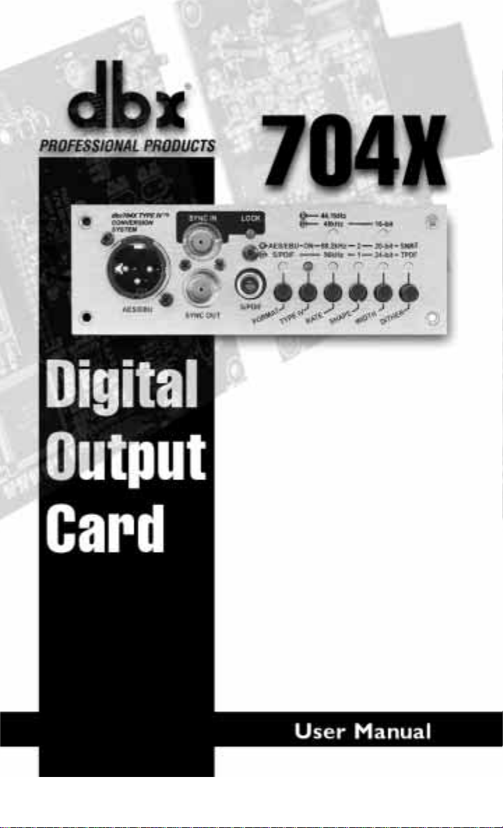
• Sample rates at 44.1, 48, 88.2, and 96 kHz
• Wordlength output at 16, 20, or 24 bits
• Dither to 16, 20, or 24 bits using TPDF or SNR
2
algorithms
• dbx Type IV™ A/D Conversion System
• Sync input/output using low jitter phase-locked loops
• Two user selectable noise shaping algorithms for lower perceived
noise floor
• Digital output on gold plated connectors
• Can be installed in a dbx 160S/SL Compressor or a dbx 786
Precision Microphone Preamplifier
If you require technical support, contact dbx Customer
Service. Be prepared to accurately describe the problem. Know the
serial number of your unit - this is printed on a sticker attached to
the rear panel. If you have not already taken the time to fill out
your warranty registration card and send it in, please do so now.
Before you return a product to the factory for service, we recommend you refer to the manual. Make sure you have correctly followed installation steps and operation procedures. If you are still
unable to solve a problem, contact our Customer Service
Department at (801) 568-7660 for consultation. If you need to
return a product to the factory for service, you MUST contact
Customer Service to obtain a Return Authorization Number.
Service Contact Information
Introduction
Digital Output Card
704X Digital Output Card
®
1

No returned products will be accepted at the factory without a
Return Authorization Number.
Please refer to the Warranty below, which extends to the first
end-user. After expiration of the warranty, a reasonable charge will
be made for parts, labor, and packing if you choose to use the factory service facility. In all cases, you are responsible for transportation charges to the factory. dbx will pay return shipping if the unit
is still under warranty.
Use the original packing material if it is available. Mark the
package with the name of the shipper and with these words in red:
DELICATE INSTRUMENT, FRAGILE! Insure the package properly. Ship prepaid, not collect. Do not ship parcel post.
This warranty is valid only for the original purchaser and only
in the United States.
1. The warranty registration card that accompanies this product
must be mailed within 30 days after purchase date to validate
this warranty. Proof-of-purchase is considered to be the burden
of the consumer.
2. dbx warrants this product, when bought and used solely within
the U.S., to be free from defects in materials and workmanship
under normal use and service.
3. dbx liability under this warranty is limited to repairing or, at
our discretion, replacing defective materials that show evi-
dence of defect, provided the product is returned to dbx WITH
RETURN AUTHORIZATION from the factory, where all
parts and labor will be covered up to a period of two years. A
Return Authorization number must be obtained from dbx by
Warranty
704X
704X Digital Output Card
2
®
®
telephone. The company shall not be liable for any consequential damage as a result of the product's use in any circuit or
assembly .
4. dbx reserves the right to make changes in design or make additions to or improvements upon this product without incurring
any obligation to install the same additions or improvements
on products previously manufactured.
5 The foregoing is in lieu of all other warranties, expressed or
implied, and dbx neither assumes nor authorizes any person to
assume on its behalf any obligation or liability in connection
with the sale of this product. In no event shall dbx or its dealers be liable for special or consequential damages or from any
delay in the performance of this warranty due to causes beyond
their control.
1. Remove lid of the 160SL or 786 by removing 6 phillips head
screws (2 each side, 2 on the back) and 1 hex screw (top and
center of front panel).
2. Remove the 4 silver screws holding the option cover plate on
the rear.
3. Place the 704X in the 160SL/786 from the inside and note
mounting holes labeled "A", "B", and "C".
4. Remove the 704X and then remove the 3 screws mounted in
the 160SL/786 main board directly below points "A", "B", and
"C" when the 704X is installed.
5. Install the 3 taller threaded standoffs where the three screws
were removed.
6. Install the ribbon cable onto the blue header in the 160SL/786
next to the power supply housing.
7. Install the 704X by placing it in the 160SL/786 and then
replacing the 4 silver screws into the rear option slot.
Installation
Digital Output Card
704X Digital Output Card
®
3
8. Install one of the three screws removed from the main board at
point "C" on the 704X.
9. Install the two shorter standoffs at points "A" and "B" on the
704X.
10. Insert the ribbon cable from the main board to the blue connector on the 704X.
11. Install the upper 704X PCB by lining up the two standoffs with
the mounting holes on the upper PCB.
12. Install the last two screws into the standoffs holding the upper
704X PCB.
13. Replace cover.
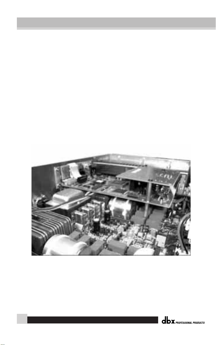
dbx 704X installed in a 786 Mic Preamp
704X
704X Digital Output Card
4
®
®
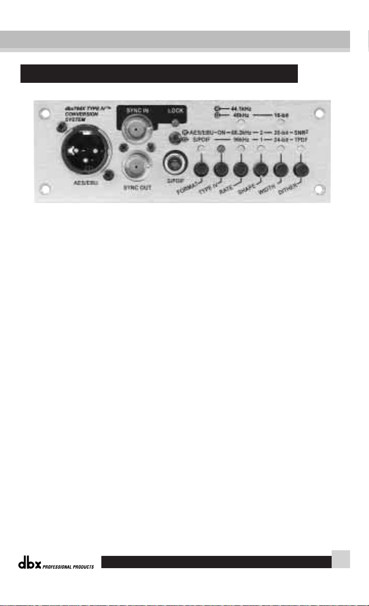
AES/EBU OUTPUT Connector: The 704X provides AES/EBU
digital output format through the XLR connector. Be sure to use
short lengths of 110Ω digital cables rather than standard XLR to
XLR cables. Using the correct cables will prevent digital dropouts
and other interconnect problems.
SYNC IN and OUT Connectors: BNC connectors are provided
for both sync in and out. The 704X uses low jitter phased-locked
loops to slave to another unit’s wordclock output through the
704X’s SYNC in jack. The 704X will accept a 44.1, 48, 88.2, or 96
kHz wordclock input, or a 44.1 or 48kHz superclock (256X sample
rate). You also may use the 704X as a master clock through the
SYNC out BNC jack to supply stable clocks to other processors
that accept a sync input. See "Sync Input" for further information.
SYNC LED: The SYNC LED will light red when the 704X is
locked to an external clock through the SYNC IN BNC jack. Note
that one of the RATE LEDs will light to indicate the clock frequency of the external source.
Rear Panel
Digital Output Card
704X Digital Output Card
®
5

S/PDIF OUTPUT Connector: The 704X provides S/PDIF digital
output format through the RCA coaxial connector. Be sure to use
short lengths of 75Ω digital cables or 75Ω video cables rather standard audio RCA to RCA cables. Using the correct cables will prevent digital dropouts and other interconnect problems.
NOTE: Although digital information is coming out of both XLR and RCA
jacks simultaneously, the correct format will only appear at the output for the
format type selected. For example, if you have AES/EBU format selected, an
AES/EBU formatted signal will appear at the output of both the XLR and the
RCA connector. Or, if you have S/PDIF format selected, an S/PDIF formatted signal will appear at the output of both the RCA and XLR connectors.
AES/EBU / S/PDIF Switch: Selects either AES/EBU format or
S/PDIF digital output format. The LED will be red for AES/EBU
and green for S/PDIF.
TYPE IV Switch: Engages dbx’s proprietary Type IV™ analog to
digital conversion system. See page 9 for more information on Type
IV™.
RATE Switch: Selects output sample rate of 44.1, 48, 88.2, or 96
kHz. The upper LED will light red for 44.1 kHz and green for 48
kHz. The lower LED will light red for 88.2 kHz and green for 96
kHz.
SHAPE: Selects noise-shaping curve of SHAPE 1, SHAPE 2, or
none. Noise shaping essentially takes the noise floor and reshapes
it in a fashion such that the ear perceives the noise floor to be quieter than it really is. See "Noise Shaping" graph on page 20. The
LED will light green for Shape 1 and red for Shape 2. When the
LED is off, there is no noise shaping taking place.
704X
704X Digital Output Card
6
®
®

WIDTH Switch: Selects output wordlength of 16, 20, or 24 bits
output resolution. The upper LED will light green for 16 bits. The
lower LED will light red for 20 bits and green for 24 bits.
DITHER: Selects dither type of TPDF, SNR
2
, or None. Dither is
random noise that is added to the audio signal which effectively
eliminates the harmonic distortion created by truncation. See
“TPDF Dither” and “Truncation” graphs on pages 19 and 20. The
LED will light red for SNR
2
and green for TPDF. When the LED
is off, there is no dithering taking place.
The dbx 704X comes with the sync input 75Ω terminated. For
certain configurations, you may wish to have the sync input be
unterminated. Certain "house sync" configurations will require you
to change the default position of the termination jumper on the
main circuit board. For example, if you run your sync to several
pieces of equipment using a tapped configuration (using BNC T’s)
as shown on the next page, only the last box, box C, would be terminated (marked "Terminated" on the circuit board).
Unfortunately, some equipment does not allow the user to change
the termination setting. These pieces of equipment are usually provided with a permanent termination. If you use the 704X with
another piece of terminated equipment in tapped configuration,
you should unterminate (marked "Unterminated" on the circuit
board) the 704X’s sync input. The same is true if you wish to use
several 704Xs in a tapped configuration. The dbx 704X can also be
used in a daisy chain fashion where each piece of equipment can
remain terminated so the termination can remain in the default
"terminated" position. See figure on the next page for location of
the termination jumper.
Sync Input
Digital Output Card
704X Digital Output Card
®
7

704X
704X Digital Output Card
8
®
®
Daisy Chain Configuration
Sync Source A 704X C
Tapped Configuration
Sync Source A 704X C

dbx Type IV™ Conversion System
White Paper
by Roger Johnson
The dbx Type IV™ Conversion System is a proprietary analogto-digital (A/D) conversion process that combines the best attributes of digital conversion and analog recording processes to preserve the essence of the analog signal when it is converted to a digital format. dbx Type IV™ not only exploits the wide linear
dynamic range of today’s A/D converters, but also enhances it and
extends the useable dynamic range beyond the linear range. By
providing a logarithmic “Type IV™ Over Region” above the linear
A/D range, we benefit from the extended high-level headroom
that is inherent in analog recording without compromising the
noise performance of the A/D conversion process.
Digital conversion and recording processes proliferated in the
1980’s primarily due to the “cleaner” sound of digital versus analog,
an advantage resulting from the comparatively wider linear
dynamic range of digital. Anyone who is familiar with the technical specifications of digital equipment knows that the typical maximum signal-to-noise specifications for 16-bit systems is in the
neighborhood of 90-something dB. Compare this to the typical signal-to-noise specifications for professional analog tape of about 55
Digital Output Card
704X Digital Output Card
®
9

dB without the aid of noise reduction and around 75 to 85 dB with
noise reduction such as dbx Type I™ or Type II™ applied.
This seemingly tremendous signal-to-noise advantage of digital
over analog would suggest that digital would become the unanimous choice for recording. For the most part this has occurred, not
totally due to its signal-to-noise advantage, but as much due to the
benefits of digital storage such as random access and the inherent
ability to withstand degradation, unlike that of analog tape or LP’s.
In spite of the benefits of digital, no one in the audio world can
refute the rediscovery of analog recording and tube gear that has
occurred in the 90’s, attributable to the quest for that “analog character” that is missing from digital recordings. This continued use of
analog gear with modern digital systems brings to light a favorable
characteristic of analog recording which those who abandoned
analog and jumped on the digital bandwagon were either never
aware of or simply took for granted.
Anyone who has ever used analog tape knows that you can “hit
it hard” without destroying the recording. The printed specifications of analog tape don’t take into account the practical headroom available. The max signal-to-noise specification of analog
tape is measured by defining the “max” signal as the point where a
given signal level and frequency produces a given percent Total
Harmonic Distortion (THD)—typically the level at which a 1 kHz
signal produces 3% THD. In actual use, the signal can easily
exceed this “max” signal level by 5, 10, or even 15 dB on peaks,
depending on the type of signal being recorded, without unacceptable artifacts. High signal levels can be tolerated (i.e. more headroom) at the expense of increased THD which, incidentally, is
often desirable as an effect, evidenced by the renewed popularity of
tube equipment.
704X
704X Digital Output Card
10
®
®

The obvious conclusion is that analog recording actually has
more useable dynamic range than the specifications seem to indicate. For example, let’s say we’re recording a kick drum. If analog
tape measures 55 dB from the 3% THD point down to the RMS
noise floor and the peaks of the kick drum exceed the 3% THD
level by, say, 15 dB and it still sounds good, then we have 15 dB of
extra useable headroom. Therefore, we end up with 70 dB of useable dynamic range. Throw in noise reduction and we push into
the 90-something dB dynamic range territory of 16-bit digital. This
explains why well-recorded analog master tapes make good-sounding CD’s with no objectionable noise.
One main drawback of digital is that it inherently lacks this
forgiving and beneficial characteristic of analog recording.
Although digital conversion exhibits wide linear dynamic range,
when you run out of headroom for high-level signals, hard clipping
or even ugly signal wrap-around occurs, not to mention that A/D
converters have their own nasty side effects such as going unstable
when their modulator is overdriven with high-level signals.
This shortcoming of digital conversion has drastically affected
the way users operate their equipment. Users are paranoid of overdriving the converter input and end up recording at lower levels to
ensure that there is ample headroom to allow for the large peaks
that would ruin an otherwise perfect recording. This, of course,
compromises signal-to-noise performance since the signal is now
closer to the noise floor. Because users of digital equipment have to
be extremely careful not to exceed 0 dB FS (full-scale), they must
use peak-reading headroom meters. On the other hand, the forgiving nature of analog tape allows users of analog recording equipment the luxury of only needing to monitor the average level using
VU meters, often having no peak indicators whatsoever. If only
dbx Type IV™ White Paper
704X Digital Output Card
®
11

digital were more forgiving like analog, we could really exploit its
wide dynamic range and more completely capture the essence of
the musical performance.
Enter the dbx Type IV™ Conversion System. Like its related
predecessor technologies—Type I™, Type II™, and Type III™—
dbx Type IV™ succeeds in preserving the wide dynamic range of
the original analog signal within a limited dynamic range medium.
Whereas Type I™ and T ype II™ expand the dynamic range of analog tape and other limited dynamic range media, and the simultaneous encode/decode process of Type III™ similarly expands the
limited dynamic range through minimum-delay devices, Type IV™
breaks new ground by greatly enhancing the useable dynamic
range of the analog-to-digital conversion process.
The dbx Type IV™ Conversion System combines proprietary
analog and digital processing techniques to capture a much wider
dynamic range than the A/D converter could by itself, preserving
the maximum amount of information from the analog signal. This
information is then encoded within the available bits of whichever A/D converter is used. This means that Type IV™ improves the
performance of any A/D converter, from low-cost 16-bit to highperformance 24-bit! And no decoding is necessary beyond the conversion process!
As we have previously mentioned, digital systems have a wide
linear region compared to analog tape and the dynamic range of
A/D converters has improved significantly in recent years. The dbx
Type IV™ Conversion System takes advantage of this and utilizes
the top 4 dB of the A/D converter’s linear dynamic range to create
a logarithmic “overload region.” This allows high-level transient
signals passing far above the point where the overload region
704X
704X Digital Output Card
12
®
®

begins to be adequately represented in just 4 dB of the converter’s
dynamic range, whereas a typical A/D converter would clip. With
Type IV™, you can never clip the A/D converter!
Fig. 1 illustrates this concept showing the level of the converted signal below and above the start of the overload region. The
converted signal level is plotted along the Y-axis (vertical axis) of
the plot vs. the level of the input signal along the X-axis (horizontal axis). The logarithmic mapping of the overload region begins 4
dB below 0 dB FS (full-scale) of the A/D converter. What this
shows is that below -4 dB FS, in the linear region, the output signal is the same as the input signal. Above this, in the logarithmic
region, high-level input signals get “mapped” into the top 4 dB of
dbx Type IV™ White Paper
704X Digital Output Card
®
13
Converted
Signal
Level
dB FS
A/D Clip Point
0
h
t
i
r
a
g
o
-4
Linear Region
L
n
o
i
g
e
R
c
i
m
-4
0 +4 +8 +12
Figure 1 - Converted Level vs. Input Level
dB
Input
Signal
Level

the A/D converter. This mapping is analogous to the signal compression effect that occurs when recording high-level signals onto
analog tape.
Fig. 2 illustrates the mapping function in a different way. Input
levels are shown on the left of the graph, while converted levels are
shown on the right. Notice the mapping of large signal excursions
to the 4 dB “Type IV™ Over Region.”
One might question the validity of such an approach—trying
to represent a lot of signal information within a smaller “space.”
The reason why this is not only valid but makes a whole lot of
sense is that the digital codes in a converter are linear, or evenlyspaced, meaning that each consecutive code represents the same
change in voltage of the input signal. This implies that half of the
704X
704X Digital Output Card
14
®
®
Input
Signal
Level
TYPE IV™
Over
+12
+8
+4
0
-4 dB -4
A/D Converter
Linear Region
Figure 2 - Input Signal Levels Mapped to Type IV Over Region
Region
0 dB FS
Noise Floor

digital codes are used to represent input signals whose voltage level
is below 1/2 of the full-scale A/D input voltage, while the other
half of the codes are used to represent signals above 1/2 of the fullscale A/D input voltage. This seems reasonable until you realize
that 1/2 of the full-scale input is only 6 dB below full-scale! So half
of the codes are used to represent only the top 6 dB of signal information, while the other half are used to represent the remaining 80
to 110 dB of signal information, depending on the quality of the
converter. It seems not only reasonable, but also desirable, to utilize the increased signal resolution afforded by this density of digital codes to represent more input dynamic range in this region.
Another advantage of the logarithmic mapping of our dbx
Type IV™ Conversion System is that it preserves the high-frequency detail of the signal in the overload region. Figs. 3a through
3d illustrate what happens when you overload an A/D converter
without Type IV™. Fig. 3a shows an input signal having both lowfrequency and high-frequency components. When the signal overloads, or clips, (Fig. 3b) at the A/D converter, a disproportionate
amount of high-frequency signal information is lost compared with
the low-frequency information. The low and high-frequency components of the signal are separated in Fig. 3c to illustrate this more
clearly. As you can see, the low frequency signal simply gets distorted but maintains most of its signal characteristics, while sections of the high-frequency signal are completely lost! With dbx
Type IV™, its mapping preserves high-frequency signal information, as illustrated in Fig. 3d, since the signal is confined within the
Type IV™ Over Region and never clips. The dashed line indicates
the original input signal level. Below the Over Region no mapping
occurs, while above this, mapping keeps all peaks of the signal
below the A/D clip level, thus preserving the high-frequency content of the signal.
dbx Type IV™ White Paper
704X Digital Output Card
®
15

704X
704X Digital Output Card
16
®
®
Amplitude
Amplitude
A/D Clip Level
Time
A/D Clip Level
Figure 3b - Signal of Fig. 3a Going Beyond the A/D Clip Level
High-Frequency Information Completely Lost
High-Frequency Information Completely Lost
Figure 3c - Disproportionate Loss of High-Frequency Information Due to Clipping
High-Frequency Content
A/D Clip Level
Low-Frequency Content
Time
A/D Clip Level

Now you’re probably wondering, “What’s the catch? I can’t get
something for nothing so what did I give up?” You may be worried
that your A/D noise floor got 4 dB worse because we borrowed the
top 4 dB of your converter. This is certainly a valid concern.
Fortunately, we have the answer! Without going into the confidential technical details, by using our proprietary analog and digital Type IV™ processing, we reclaim the original A/D noise level!
So what you get is free headroom!
The benefits of the dbx Type IV™ Conversion System can easily be heard by switching it in and out while listening to signals
with high-level peaks captured in the Type IV™ Over Region. You
will notice an obvious audible difference. With Type IV™
bypassed, you can’t help notice the harsh, edgy sound of the A/D
converter clipping. With Type IV™ enabled, those nasty artifacts
disappear revealing a more open and natural sound. With Type
IV™ enabled, you will get a more accurate and pure representation
of the original wide-dynamic-range signal. You will absolutely
agree that we really do give you “something for nothing.” We give
you peace of mind knowing that you never have to worry about
Amplitude
dbx Type IV™ White Paper
704X Digital Output Card
®
17
0 dB FS
-4
-4
0 dB FS
Figure 3d - Type IV Mapping Preserves High-Frequency Information
A/D Clip Level
TYPE IV™ Over Region
}
Time
TYPE IV™ Over Region
}
A/D Clip Level

clipping your A/D again! And when you listen to the noise floor of
your A/D, you’ll realize that we never compromise your noise performance with Type IV™!
The dbx Type IV™ Conversion System succeeds in combining
the best of the analog and digital worlds to capture the truest
essence and fullest dynamic range of audio signals. Who else but
dbx would bring you this technology!
704X
704X Digital Output Card
18
®
®

A-D Conversion: 24 bit, dbx Type IV™ Conversion System
Converter Dynamic Range: 114 dB unweighted, 22 kHz bandwidth,
Type IV™ engaged
117 dB "A" weighted, 22 kHz bandwidth,
Type IV™ engaged
Type IV™ Dynamic Range: Up to 127dB with transient material, A-
weighted, 22-kHz bandwidth
THD+Noise: <0.002% typical at -21.5dBFS, 1 kHz
Frequency Response: 20 Hz to 20 kHz, +0/-0.5 dB
Interchannel Crosstalk: <95 dB at 1kHz
Sync Input Lock Range: 41.7 kHz to 49.9 kHz
83.4 kHz to 99.8 kHz
NOTE: +4dBU= -21.5dBFS
Specifications
Digital Output Card
704X Digital Output Card
®
19
TPDF Dither. (a) 24-Bit word output, (b) 16-Bit word output. Parameters: Input 60dBFS, 1 kHz; FFT Length= 2048, Sample Rate= 48 Khz, Averages= 32; Graph
Steps= 1024.

704X
704X Digital Output Card
20
®
®
16-Bit TPDF dither. (a) Shape “off”, (b) with shape set to “S1”, (c) with shape set
to “S2.” Parameters: Input -60dBFS, 1 kHz; FFT Length= 2048, Sample Rate= 48 Khz,
Averages= 32; Graph Steps= 1024.
(a) 24-Bit word, (b) 16-Bit truncated output, no dither. Parameters: Input -60dBFS,
1 kHz; FFT Length= 2048, Sample Rate= 48 Khz, Averages= 32; Graph Steps= 1024.

8760 South Sandy Parkway
Sandy, Utah 84070
Phone: (801) 568-7660
Fax (801) 568-7662
Int’l Fax: (801) 568-7583
Questions or comments?
E-mail us at: customer@dbxpro.com
or visit our World Wide Web home page at:
www.dbxpro.com
A Harman International Company
Part No: 18-6315-A
 Loading...